Preventive Maintenance Protocol
8
Preventive Maintenance Protocol 890580
Transcript of Preventive Maintenance Protocol
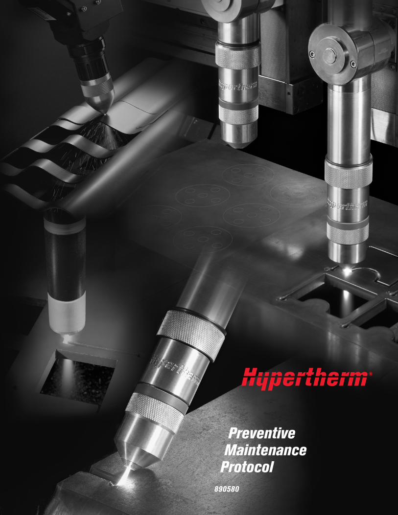
PreventiveMaintenance
Protocol
890580

Preface
Hypertherm designs its plasma cutting systems to stand up to rugged industrial use. To optimizeperformance, minimize overall operating costs and prolong system life, a regular maintenancepractice should be followed. In response to customer input, Hypertherm developed a PreventiveMaintenance Protocol which it has offered through its Technical Service Department. Because wefeel proper maintenance is so critical to efficient and low-cost system operation, we have puttogether this booklet which describes the Hypertherm protocol so that OEMs and technicallycapable distributors may use it directly with their customers.
Deteriorating consumable parts life is frequently one of the first symptoms to indicate thatsomething is wrong with a plasma system. Reduced parts life dramatically increases operatingcosts for two reasons: first, and perhaps most obvious, shorter consumable life means that theend user will have to use more consumables to cut the same amount of metal. The second, andeven more important factor, is that shorter consumable life means that the end user must shutdown his cutting operation to change consumables more often. In an average cutting operation,labor and overhead can account for over 80% of the cost of cutting, so improved productivity, inthe form of less downtime, can reduce cutting costs dramatically.
Proper maintenance often eliminates problems that lead to shortened consumables life. Sincereduced cutting costs and increased productivity are key reasons why end users purchaseHypertherm systems, maintaining a system in proper operating condition is important to ensuringcustomer satisfaction.
The Preventive Maintenance Protocol is intended to be simple to follow. After you have performedit a few times, you should expect to take approximately 3 hours to complete it for each individualplasma system involved.
Hypertherm wants to meet or exceed customers’ expectations. We hope that this booklet will helpyou accomplish this with your customers.

Preventive Maintenance Protocol
The following protocol covers the basic elements of a Hypertherm mechanized plasma system.These basic elements apply broadly to all our mechanized systems, although certain specificcomponents, such as the high-frequency console or the water coolant system, are not present inall mechanized systems. The protocol may therefore vary slightly from a MAX100D to a HySpeedHT2000, for example, and as we move through the protocol, we have tried to note where certainsteps would not be necessary for certain systems.
It is important to have available for reference a copy of the appropriate manual for the Hyperthermsystem to be maintained.
If inspection suggests that a component is worn and might require replacement, and youwould like confirmation of your recommendation, please contact Hypertherm’s TechnicalService department.
When performing preventive maintenance on any plasma system power supply, it is critical to shut
off power to the power supply at the source. Extreme electrical hazard is present in the power supply
and at the torch Please consult the manual for a complete list of safety precautions.
1. With power to the power supply off, remove all side panels and inspect for accumulated dust. Using compressed air, blow out the inside of the power supply to remove dustand particulates.
2. Inspect wiring harnesses and connections for any wear or damage. Check for looseconnections and look for any discoloration that might indicate overheating. If this condition isobserved, contact Hypertherm Technical Service.
3. Inspect the main contactor for excessive pitting, characterized by a blackened, rough surfaceon any of the contacts. If this condition exists, replacement should be recommended.
4. If the plasma system has an air filter on the front panel of the power supply, inspect the airfilter and recommend replacement if dirty.
5. Inspect the pilot arc relay (CR1 ) for excessive pitting on the contacts, characterized by aroughened, black surface. Recommend replacement if necessary.
The power supply
Preventive Maintenance Protocol (cont.)
6. If the plasma system has a built-in coolant system, inspect the filter element of the coolantsystem which is located at the rear of the power supply. If the filter has begun to turn abrownish color, a replacement particle filter should be recommended. Refer to the manualfor proper part numbers.
7. Perform a coolant flow test on the system. For MAX200, HT2000, HD1070 and HD3070systems, flow should be at least 0.75 gpm (2.8 L/min) on the return line. For HT4400 andHD4070 systems, flow should be 1.0 gpm (3.7 L/min). When testing systems with externalwater chillers, the required coolant flow varies according to different size pumps. Refer toappropriate manuals.
Check for coolant leaks. Primary locations to inspect are: 1) the back of the power supply;2) at the high-frequency console, if applicable; and, 3) at the torch main body. Check theholding tank for dirt and particulates. Verify that proper Hypertherm coolant is being used.
8. If the torch contains a water tube for electrode cooling, check the water tube to ensure thatit is straight and has no pitting on the end. It should also be securely screwed into the torchmain body.
9. Check the current ring inside the torch main body. The current ring should be smooth andnot pitted. If even slight pitting is seen, replacement should be recommended. If no pittingis observed, clean the current ring with a clean cotton swab and clean water. Do not use
alcohol. Pitting on the current ring generally indicates improper maintenance i.e. lack ofregular cleaning).
10. Clean all threads on the front end of the torch head with clean water and a cotton swab,pipe cleaner or clean cloth. Do not use alcohol. Damage to the threads usually results fromnot properly cleaning the torch and retaining cap threads, so that dirt and particulatesaccumulate in the threads.
11. Inspect the Vespel® torch insulator for cracks. Replacement of the torch should berecommended if cracks are found.
12. Inspect all O-rings on the torch body and consumables. Make sure that the correct amountof lubricant is being applied to these O-rings. Too much lubricant may obstruct gas flows.
13. Ensure that the retaining or shield cap is tightened securely to the torch main body.
14. Check all hose fittings at the rear of the torch for wear. Damage to the fitting threads mayindicate that overtightening has occurred.
15. Ensure that all connections between the torch and torch leads are tight, but donot overtighten.
When removing consumables, always place them on a clean, dry, oil-free surface, sincedirty consumables may cause the torch to malfunction.
Torch main body
Coolant system

16. Check the plumbing from the gas supply source, as follows:
A. Remove and plug the oxygen inlet gas fitting at the gas console.
B. Pressurize the gas system at the source to 120 psi (8.3 bar).
C. Close the gas supply valve at the source. Watch for a pressure drop. If the supply linefrom the source is a hose, there may be a 5 to 7 psi (0.3 to 0.5 bar) drop due to stretch.
D. If the pressure continues to drop, find the leaks in the system.
E. Perform the same protocol for the nitrogen gas supply system, except that the gassystem should be pressurized at the source to 150 psi (10.3 bar) for the HT4001 and120 psi (8.3 bar) for all other systems.
F. Perform the same protocol for the air, carbon dioxide or argon-hydrogen and methanesupplies (as applicable) except that the gas system should be pressurized at the sourceto 120 psi (8.3 bar).
G. If the system is operating on compressed air, verify that a drying and filtering system is inplace to ensure that no oil or moisture is allowed to enter the plasma system. Inspect allfilters and oil separators and recommend replacement if dirty.
17. Perform a system gas leak test, as follows:
A. Place the gas console in the Test Preflow mode. Adjust gas flows to appropriate settingsas outlined in the operation section of the instruction manual.
B. Locate the off-valve solenoid and disconnect the control cable from the solenoid.The balls in the flow meter should slowly drop to zero. If they do not, a leak maybe indicated.
C. Close the shut-off valves for the oxygen and nitrogen supply at the source.
D. The pressure gauges on the gas console should maintain their pressure. If either nitrogenor oxygen pressures drop more than 2 psi (0.1 bar) in 10 minutes, there isan unacceptable leak.
E. If a leak is indicated, check all gas connections, using a soapy water solution.
F. For HT4400 and HD4070 systems, follow the gas leak test as outlined in those manuals.
Gas flows
Preventive Maintenance Protocol (cont.)
18. Check for hose restrictions, as follows:
A. Check the 3 hoses connected to the motor valve. Make sure that they are not bent,causing a possible restriction.
B. Check the gas hoses from the gas console to the motor valve, looking for any sharpbends that may cause restrictions.
C. Check the off-valve hose from the off-valve to the torch main body. Make sure that thehose is not bent, causing a restriction.
D. If the cutting table uses a power track system to support leads from the power supply tothe gas console or torch, check the position of the leads in the power track to ensure theleads do not twist or kink, causing a possible restriction.
19. Cables should be checked for chafing or unusual wear. If the outside insulation has beencut, check the wires inside for damage:
A. For Initial Height Sensing (IHS) option, check the cables from the inductive probes to theIHS console.
B. Check the control cable from the off-valve to the motor valve console.
C. Check the cable from the motor valve console to the power supply.
D. Check control cables from the high-frequency console and the gas console to the powersupply.
Cable connections
20. Open the cover and inspect the interior for condensation or the accumulation of dust andparticulate If dust and particulates are present, blow out the unit with compressed air.If moisture is present, dry the inside of the console with a cloth and contact HyperthermTechnical Service for recommended action.
21. Inspect the spark gap subassembly. Inspect the 3 electrodes. Verify that the electrodes are0.020" (0.508 mm) apart and that they are clean and the ends are flat. File the electrodesclean with a diamond file if necessary. Ensure that the wiring connections to the spark gapsubassembly are secure. Check that the console doors are properly closed.
22. Inspect the torch leads. Ensure that they are fastened tightly to the outside of the high-frequency console.
High-frequency console (if applicable)
Preventive Maintenance Protocol (cont.)

23. Verify that all components of the system are individually grounded to a driven earth ground,as described in the instruction manual.
A. All metal enclosures, such as the power supply, high-frequency console and gas console,should be connected individually to a ground point. These connections should be madewith #8 AWG wire (USA), or equivalent-size wire.
24. Check the connection from the cutting table to the workpiece (+) lead. Particularly inspectwhere the positive (+) lead connects to the cutting table to ensure that it is a good, cleanconnection. A poor connection may cause arc transfer problems.
System grounding
Preventive Maintenance Protocol (cont.)

Gas flows (cont.)�P �NP 17. Perform gas leak test
A. Oxygen pressure drop at _________psi in 10 minutes ( ____________ bar)
B. Nitrogen pressure drop at _________psi in 10 minutes ( ____________ bar)
�P �NP 18. Inspect for hose restrictions�P �NP A. Motor valve hoses�P �NP B. Gas console to motor valve�P �NP C. Off-valve to torch body�P �NP D. Hoses in power track
Cable connections�P �NP 19. Inspect cables
�P �NP A. From IHS probes to IHS console�P �NP B. Control cable from off-valve to
motor valve console�P �NP C. From motor valve console to
power supply�P �NP D. From high-frequency console and
gas console to power supply
High-frequency console�P �NP 20. Inspect for moisture, dust and particulates�P �NP 21. Inspect spark gap subassembly
A. Electrode gap range _________to ____________
�P �NP 22. Inspect torch leads
System grounding�P �NP 23. Inspect for proper system
component grounding�P �NP 24. Inspect connection from cutting
table to workpiece (+ ) lead
Power supply�P �NP 1. Inspect for particulates and blow out�P �NP 2. Inspect wiring harnesses�P �NP 3. Inspect main contactor�P �NP 4. Inspect air filter on front of system�P �NP 5. Inspect pilot arc relay
Coolant system�P �NP 6. Inspect filter element�P �NP 7. Perform coolant flow test
A. Coolant flow checked at _________gallons per minute ( ____________ L/min)
Torch main body�P �NP 8. Inspect water tube
�P �NP 9. Inspect current ring
�P �NP 10. Clean threads on torch front end
�P �NP 11. Inspect Vespel torch insulator
�P �NP 12. Inspect torch and consumable O-rings
�P �NP 13. Verify proper fit of retaining or shield cap
�P �NP 14. Inspect hose fittings
�P �NP 15. Inspect torch-to-torch-lead connections
Gas flows�P �NP 16. Inspect plumbing from gas supply
�P �NP A. Oxygen�P �NP B. Nitrogen�P �NP C. Air�P �NP D. CO2
�P �NP E. Argon-hydrogen�P �NP F. Methane�P �NP G. Inspect compressed air filter system
General comments and recommendations:___________________________________________________________________________________________________________________________________________________________________________________________________________________________________________________________________________________________________________________________
Preventive Maintenance Protocol ChecklistCustomer: ____________________Location:______________________Contact: ______________________Date:_________________________
Hypertherm system: _____________System serial #:_________________System arc hours: _______________(if equipped with an hour meter)
Comments P - Performed NP - Not present on system
Preventive maintenance performed by: __________________________________________ Date:_______________6/17/03