
Preventing DNS Ampli cation Attacks using white- and greylisting
32
University of Amsterdam System & Network Engineering Preventing DNS Amplification Attacks using white- and greylisting July 23, 2013 Author: Ralph Dolmans [email protected]
Transcript of Preventing DNS Ampli cation Attacks using white- and greylisting

University of Amsterdam
System & Network Engineering
Preventing DNS AmplificationAttacks using white- and
greylisting
July 23, 2013
Author:Ralph Dolmans [email protected]
Abstract
The amplification factor caused by the Domain Name System (DNS) can be usedto perform massive Distributed Denial-of-Service (DDoS) attacks. In an attemptto mitigate this problem, RFC5358 describes that a Recursive Resolving NameServer (RRNS) should provide its service solely to its intended users. Theseintended users can be listed on a local whitelist.
For an Authoritative Name Server (ANS) there are no standards to restrictaccess to exclusively its intended users, which would defy attacks from unin-tended users. The intended users of ANSs are RRNSs. However, DNS Amplifi-cation Attacks are typically targeted at worldwide services, such as webserversand ANSs. By creating a global whitelist that contains all RRNSs these attackscan be mitigated.
A global whitelist can be created by logging source addresses from requeststhat are received at an ANS. Custom ANS software is built that uses the be-havior of CNAME handling to emulate handshakes and prove that requests arenot spoofed. Software firewalls can be deployed to effectively limit the numberof responses sent to non intended users.
This research shows that the proposed solution covers all the attack vectors.It also offers a practical implementation that seems feasible to execute, assumingenough RRNS servers can be collected.

Contents
1 Introduction 3
2 Previous work 52.1 Resolvers . . . . . . . . . . . . . . . . . . . . . . . . . . . . . . . 52.2 Authoritative . . . . . . . . . . . . . . . . . . . . . . . . . . . . . 5
2.2.1 Creation of stateful connections . . . . . . . . . . . . . . . 52.2.2 BCP38 related solutions . . . . . . . . . . . . . . . . . . . 62.2.3 ANS request thresholds . . . . . . . . . . . . . . . . . . . 6
3 Proposed solution 7
4 Proposed solution effectiveness 94.1 Amplification using a remote RRNS . . . . . . . . . . . . . . . . 94.2 Amplification using a local RRNS . . . . . . . . . . . . . . . . . . 104.3 Amplification using an ANS to an ANS or non-DNS node . . . . 104.4 Amplification using an ANS to a RRNS . . . . . . . . . . . . . . 104.5 Effectiveness per scenario . . . . . . . . . . . . . . . . . . . . . . 11
5 Practical approach 135.1 Local whitelist . . . . . . . . . . . . . . . . . . . . . . . . . . . . 135.2 Global whitelist . . . . . . . . . . . . . . . . . . . . . . . . . . . . 13
6 Practical approach feasibility 166.1 Local whitelist . . . . . . . . . . . . . . . . . . . . . . . . . . . . 166.2 Global whitelist . . . . . . . . . . . . . . . . . . . . . . . . . . . . 16
6.2.1 Latency benchmark . . . . . . . . . . . . . . . . . . . . . 176.2.2 CPU load benchmark . . . . . . . . . . . . . . . . . . . . 176.2.3 Whitelist manager . . . . . . . . . . . . . . . . . . . . . . 19
7 Considerations and future work 20
8 Conclusion 21
A Pseudo-random IP list generation script 24
B Ipset whitelist generation script 25
C Latency benchmark results 26
1

D CPU utilization benchmark results 27
E Global whitelist management tool 28
2

Chapter 1
Introduction
Many actions on the Internet, such as visiting websites and sending emails,involve the translation from domain names to IP addresses. The Domain NameSystem (DNS)[10][11] is therefore a critical component of the Internet. Anotheruse that DNS provides, is the ability to perform distributed denial-of-service(DDoS) attacks. The DDoS attack on Spamhaus (March 2013) is currentlyknown as the biggest DDoS attack and was executed using DNS[14].
The DNS infrastructure consists of two elements. One element is the Recur-sive Resolving Name Server (RRNS). The RRNS is provided by Internet ServiceProviders (ISPs) to its customers and used as central point to query and cacheResource Records. The other element is the Authoritative Name Server (ANS).An ANS contains the original Resource Records.
The reason why DNS can be used to perform DDoS attacks is the combina-tion of the used transport-layer protocol and the simplicity of the DNS protocol.The User Datagram Protocol (UDP)[12] is used for the transport of DNS re-quests and responses. Unlike the Transmission Control Protocol (TCP)[13],UDP does not use handshaking dialogues. The lack of handshaking dialoguescreates the possibility to sent a UDP packet that contains a variable sized pay-load and a spoofed source address. When a DNS request is received by a DNSserver it will reply with one response. Meaning, there is no detection of spoofedsource addresses in the application layer either. This allows a DNS server totransfer data to a node that did not request for it.
The danger of sending unsolicited data using DNS depends on the effect ofthe amplification factor. A DNS response is typically bigger than a DNS request,hence an attacker can send significantly more data to the victim compared tooriginal request. When all the downstream bandwidth of the victim’s networkis used to receive the DNS responses, the victim will not be capable to handlelegitimate requests anymore.
According to the original DNS specification, a DNS response will fit in oneUDP package and thereby is at most 512 bytes. Hence, when a 64 bytes re-quest is sent the maximum amplification factor is 8:1. In 1999 the Extensionmechanisms for DNS (EDNS0)[17] were introduced to exceed the maximum sizeof the response packet, hereby exceeding the maximum amplification factor aswell. Nowadays DNS is also used to store cryptographic keys, for example forDNSSEC[3] and DKIM[2]. The relatively big size of these keys can be abusedto create a large amplification factor. During the DNS Amplification Attack on
3

Spamhaus, requests were made to retrieve DNS Resource Records for ripe.net.The amplification factor of these requests was 100:1[15].
4

Chapter 2
Previous work
Previous research is done on methods to prevent DNS Amplification Attacksfrom occurring on RRNSs and ANSs.
2.1 Resolvers
Due to RFC5358[4], DNS Amplification Attacks that use a RRNS can be pre-vented by providing the DNS service to intended clients only. One of the sug-gested ways to do this, is by using IP address based authorization. The RRNSshould only reply when the request is coming from a local (and authorized) IP.The network containing the RRNS should be protected against external addressspoofing.
Restricting the access of a RRNS to local users is the advise in a report fromthe National Cyber Security Division, Department of Homeland security[6] too.
2.2 Authoritative
Preventing a DNS Amplification Attack on an ANS by confining access to lo-cal users is not a solution, since the service should be accessible to any user.Solutions to mitigate DNS Amplification Attacks on an ANS recommended inprevious research can be divided into three categories: creation of stateful con-nections, BCP38 related solutions and ANS request thresholds.
2.2.1 Creation of stateful connections
When the state of the connection between client and server can be stored, thepossibility to spoof the source address can be avoided. The state is generatedduring the handshaking dialogue. DNS servers should only handle requeststhat contain a state agreed upon by both parties, thereby introducing a simplechallenge-response mechanism.
Stateful connections can be created in the transport-layer. One way toachieve this is by handling the DNS traffic over TCP instead of UDP. Anotherway to create stateful connections is by saving states in the application-layer.Guo et al. proposed a method to implement this idea by using cookies betweenthe requester and a firewall in front of the ANS[8]. Kambourakis et al. proposed
5

a method requiring a validation on a RRNS whether a request was made afterreceiving a response[9]. TCPCT has been suggested to replace UDP for DNS,amongst others by Allen and William[1].
The disadvantages of storing states at a server is the establishment of newattack vectors. For example, it might be possible to create an unusual highamount of states which would result in an overload of the server. Hence, makingit unavailable.
2.2.2 BCP38 related solutions
Another way to prevent source address spoofing is by excluding the possibility ofan UDP packet containing a source address of a node that is not in the sendingnetwork segment. A method to accomplish this is by implementing BCP38[7].
The disadvantage of this method is that the responsibility of preventingsource address spoofing is situated at edge networks. When a malicious ISPrefuses to implement source address inspection, the possibility to perform DNSAmplification Attacks from within that network remains unaltered.
2.2.3 ANS request thresholds
The third category contains solutions in which the ANS decides whether therequest should be answered or not.
Vixie proposed to do this, by using DNS Response Rate Limiting (DNSRRL)[16]. In DNS RRL the server keeps track of the amount of transmittedresponses per subnet. When the amount of responses exceed a threshold, theserver will stop sending replies to a specific IP or subnet. Donnerhacke intro-duced DNS Dampening[5]. DNS Dampening works with penalty points. EveryDNS request will give the source address one point. When the amount of pointsexceed a threshold the server will drop all request containing that particularsource address.
The disadvantage of using thresholds is the occurrence of false-positives.When many legitimate requests comes from one subnet, these requests mightbe dropped. On the other hand, a problem is the occurrence of false-negatives.When the attack is distributed over a number of different ANSs the number ofrequests of each ANS can remain under the specified threshold, meaning thatthe possibility to amplify requests can not be mitigated.
6

Chapter 3
Proposed solution
A solution without the mentioned disadvantages is needed. For a RRNS thissolution lies in solely handling requests coming from intended users. The IPs ofthese intended users are specified on a local whitelist. This model is displayed infigure 3.1. RFC5358[4] withholds the practical use of this solution at an ANS,for the obvious reason that is will limit the access to a domain.
Figure 3.1: RRNS whitelisting model
When looking at the distinction of the ANS architecture an the RRNS ar-chitecture, we can deduct that the intended users for ANSs are RRNSs. Whenlooking at victims of DNS Amplification Attacks the opposite is shown. Vic-tims are typically servers whose services are intended to be used by anybody,for example a webserver or an ANS, and not a RRNS.
By using a global whitelist that contains all RRNSs, the impact of DNSAmplification Attacks can be mitigated. ANSs should respond to requests reg-ularly, when the source address in the requests is on the global whitelist. Thesame model as with RRNSs can be used. This solution excludes the possibilityto perform a DNS Amplification Attack on an ANS or a non-DNS server.
At times it might be useful to have direct access to an ANS without the in-tervention of a RRNS, for example when debugging. Therefore, requests comingfrom an address that is not on the whitelist should not instantly get dropped.Instead, the IPs that are not on the whitelist should be handled as greylisted.When an IP is considered to be on the greylist, the ANS would limit the num-ber of responses. This model is displayed in figure 3.2. The limit would preventthe possibility to transfer data with such a big amount that it could overload aserver.
The server side source address verification rules for the proposed solution
7

Figure 3.2: ANS white- and greylisting model
are:
RRNS-1 source address of DNS request packet on the whitelist → handlerequest normally;
RRNS-2 source address of DNS request packet not on the whitelist → droprequest;
ANS-1 source address of DNS request packet on the whitelist→ handle requestnormally;
ANS-2 source address of DNS request packet not on the whitelist → ratelimitresponse.
8

Chapter 4
Proposed solutioneffectiveness
To prove the effectiveness of the proposed solution it is necessary to create anoverview of all the variations on a DNS Amplification Attack. The differentattack scenarios can be divided into four categories, which contain two or fourscenarios:
4.1 Amplification using a remote RRNS
Scenario 1 Attacker not located in network of victim; amplifier not located innetwork of victim and attacker; RRNS is used for amplification.
Scenario 2 Attacker not located in network of victim; amplifier located innetwork of victim; RRNS is used for amplification.
Figure 4.1: Amplification using a RRNS. RRNS is not located in victims net-work, victim can be any type of node.
9

4.2 Amplification using a local RRNS
Scenario 3 Attacker not located in network of victim; amplifier is located innetwork of attacker; RRNS is used for amplification.
Scenario 4 Amplifier, attacker and victim are located in the same network;RRNS is used for amplification.
Figure 4.2: Amplification using a RRNS. RRNS is located in victims network,victim can be any type of node.
4.3 Amplification using an ANS to an ANS ornon-DNS node
Scenario 5 Attacker not located in network of victim; amplifier not located innetwork of victim and attacker; ANS is used for amplification; victim isnot a RRNS.
Scenario 6 Attacker not located in network of victim; amplifier located innetwork of victim; ANS is used for amplification; victim is not a RRNS.
Scenario 7 Attacker not located in network of victim; amplifier is located innetwork of attacker; ANS is used for amplification; victim is not a RRNS.
Scenario 8 Amplifier, attacker and victim are in the same network; ANS isused for amplification; victim is not a RRNS.
4.4 Amplification using an ANS to a RRNS
Scenario 9 Attacker not located in network of victim; amplifier not located innetwork of victim and attacker; ANS is used for amplification; victim is aRRNS.
10

Figure 4.3: Amplification using a ANS. Victim can be an ANS or non-DNSnode.
Scenario 10 Attacker not located in network of victim; amplifier located innetwork of victim; ANS is used for amplification; victim is a RRNS.
Scenario 11 Attacker not located in network of victim; amplifier is located innetwork of attacker; ANS is used for amplification; victim is a RRNS.
Scenario 12 Amplifier, attacker and victim are in the same network; ANS isused for amplification; victim is a RRNS.
Figure 4.4: Amplification using a ANS. Victim is a RRNS.
4.5 Effectiveness per scenario
When a RRNS is configured to reply to requests coming from intended users only(rule RRNS-2), the attacks scenarios listed in the first category are prevented.
11

When the network containing the RRNS is protected against external addressspoofing, attack scenario 3 from the second category is prevented as well.
The attack to a local server using a RRNS, as shown in attack scenario 4,will remain possible due to rule RRNS-1. This possibility is not a big issue,since the victim can solve this problem by contacting his ISP. When BCP38 isimplemented at the ISP, this type of attack will only work when the attackerand victim are located in the same network segment.
By implementing the global whitelist validation, all attack scenarios fromthe third category are prevented (rule ANS-2). The victims in these scenariosare not on a global whitelist, therefore the responses sent to those victims arelimited.
Attacking a RRNS by amplifying data using an ANS will still be possible inthe suggested solution. This attack scenario is, however, not common. Hence, allrelevant attack scenarios are mitigated by implementing the proposed solution.
12

Chapter 5
Practical approach
5.1 Local whitelist
RRNSs form the client-side part of the DNS and are therefore located at thenetwork of an ISP or at a local network. At these locations it is known whichIPs are used inside the network. Therefore, creating a local whitelist is an easytask.
5.2 Global whitelist
The need of a complete and up-to-date global whitelist demands an automatedmethod to collect as many RRNSs as possible. Scanning the complete IP spaceas done by the Open Resolver Project1 is not possible, because RRNSs usinga local whitelist should not reply to request coming from the scanning node.Therefore, the action to whitelist a RRNS should be triggered from within theRRNS’s network.
To make the whitelist as complete as possible, it should be possible for allthe users of the network to participate in the collection process. Users shouldpreferably be able to participate without the need to install software or withoutexecuting difficult tasks.
One way to use crowd sourcing to collect RRNS addresses, is by loggingsource addresses for DNS requests that are received at an ANS. Participantsonly have to resolve the IP of a domain in that case. The ANS for that domainshould be configured to log all requests. There is, however, by default no wayto verify that the source addresses in the requests are not spoofed.
Source address spoofing can be prevented by using handshaking dialogues.A handshaking dialogue can be implemented by generating an unique validationtoken for every received request at the ANS. The generated validation token willbe included in the response that is sent to the RRNS. The RRNS should nowsend the validation token back to the ANS, thereby verifying that the tokenis received at a RRNS. It is clear that the original request does not contain aspoofed source address when the validation token sent by the RRNS equals theoriginal generated token at the ANS.
1http://openresolverproject.org/
13
It is possible to have the RRNS automatically re-send the validation tokento the ANS. Section 3.6.2 (Aliases and canonical names) in RFC1034[10] states:
CNAME RRs cause special action in DNS software. When a nameserver fails to find a desired RR in the resource set associated withthe domain name, it checks to see if the resource set consists of aCNAME record with a matching class. If so, the name server in-cludes the CNAME record in the response and restarts the query atthe domain name specified in the data field of the CNAME record.The one exception to this rule is that queries which match theCNAME type are not restarted.
This behavior can be used to create the handshaking dialogue. The ANS used forthe whitelist generation should always respond with a CNAME containing thevalidation token. The RRNS will now resent the validation token in the attemptto resolve the CNAME. The steps for executing a handshaking dialogue overthe DNS protocol are:
1. Client sent request for A record to RRNS
2. RRNS sent request for A record to ANS
3. ANS generates validation token and stores this token, together with thesource address of the request, in a database
4. ANS replies to RRNS with a CNAME resource record. The validationtoken will be included in the data field of the CNAME record. The vali-dation token will be succeeded with the domain name of the ANS.
5. The RRNS received a CNAME while requesting an A record, therefore anew request will be executed. A request to resolve the CNAME containingthe validation token is sent to the ANS.
6. The ANS can mark the source address corresponding with the validationtoken as validated. Finally the requested A record can be returned.
These steps are displayed in the sequence diagram in figure 5.1.By exporting all source addresses from the database that are marked as
validated, a global whitelist is generated.An attacker can add a server to the whitelist if he is able to retrieve the
validation token transmitted to that server. This can be done by having access tothe system or by successfully performing a Man-in-the-Middle attack. Anotherway of retrieving the right validation token is by using brute forcing techniques,i.e. trying all possibilities. The risk of brute force attacks can be mitigated bylimiting the time window in which a validation token is valid.
For this research, the custom ANS software is developed using python andthe Twisted2 library. The validation tokens and whitelist entries are stored ina MySQL database.
2http://twistedmatrix.com/
14
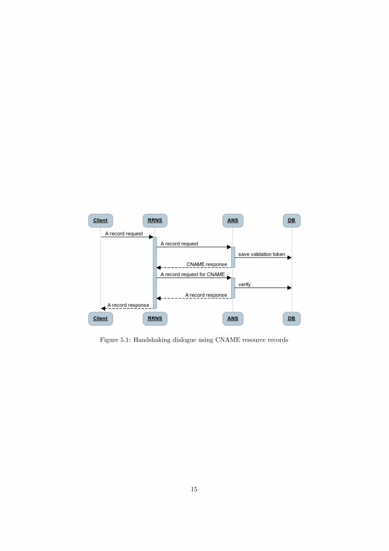
Figure 5.1: Handshaking dialogue using CNAME resource records
15

Chapter 6
Practical approachfeasibility
6.1 Local whitelist
All modern RRNS software offers the possibility to limit requests using a localwhitelist. Enabling the use of local whitelists therefore only requires a changein the RRNS configuration.
6.2 Global whitelist
ANS software does not provide the possibility to rate limit greylisted IPs. Theaccess control solutions that are available are designed for the use of a localwhitelist. It is not suitable for the high amount of entries that are available inthe global whitelist.
One location to include this additional software is in the code of the ANSsoftware. Unfortunately this will introduce some drawbacks. This solutionrequires that the whitelist check has to be included in all available ANS software.It will take a long time to finis, while there is a demand for a solution as soonas possible.
Another method to perform global whitelist validation is by using firewallsoftware. Firewalls are specialized in dropping packets that meet a specified rule.When using a firewall, a portable solution for multiple platforms is available.
To ensure a high adoption of global whitelist validation, the impact on theperformance of the DNS service caused by the validation should be limited. Twobenchmarks were executed to measure the impact.
Two identical servers (Dell PowerEdge R210, Intel Xeon L3426, 8GB RAM)were used for the benchmarks. The two servers were connected with each otherusing an Ethernet crossover cable. On the first server the DNS software andfirewall were installed. BIND1 was used as DNS software, iptables2 as firewall.Ipset3, an iptables extension, was used to store the whitelist entries in a way
1http://www.isc.org/downloads/bind/2http://www.netfilter.org/projects/iptables/index.html3http://ipset.netfilter.org/
16

that can be used in an iptables rule.The second server was deployed as monitor for the measurements. Dnsperf4
was used to send DNS requests and to measure the latency between sending therequest and receiving a response. The DNS requests were coming from the testfile5 offered by Nominum.
6.2.1 Latency benchmark
The goal of the first benchmark was to see the difference in latency when using alarge amount of entries in ipset. The benchmark was executed with 21 differentipset lists. The number of entries in these lists range from 0 to 1 million IPs,with intervals of 50 thousand.
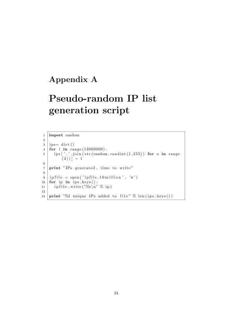
The script used to create pseudo-random IPs from the whitelists is listed inAppendix A. The script used to create the ipset lists is listed in Appendix B.The iptable rules used during the benchmark on the DNS server are:
iptables -A INPUT -m set --match-set <ipsetname> src -j DROP
iptables -A INPUT -j ACCEPT
When the source IP matches the whitelist the lookup will stop, resulting in alower latency. To prevents this it was made sure that the IP of the monitorsystem was not whitelisted. The command used to execute the benchmarks is:
dnsperf -d queryfile-10million -s 192.168.1.50 -Q 200000
The Q parameter limits the maximum number of DNS requests send per second.By limiting at 200 thousand requests we can make sure that the CPU of themonitor server is not completely used, which could alter the results.
For all performed benchmarks, using the 21 different ipsets, the averagelatency over one million requests is around 0.13 milliseconds. From these results,the conclusion can be drawn that the latency for DNS lookups does not increasewhen a whitelist containing one million IPs is used. The benchmark results aredisplayed in the chart in figure 6.1. Appendix C provides a complete overviewof the results.
6.2.2 CPU load benchmark
The goal of the second benchmark is to measure difference in CPU load on theDNS server when it is configured to limit access to global whitelisted IPs. Thebenchmark consists of three test-scenarios:
No iptables Measurements of the DNS server’s CPU load when no globalwhitelist validation is performed.
Whitelisted Measurements of the DNS server’s CPU load which is configuredto perform global whitelist validation. In this scenario, the IP of themonitor server is on the whitelist.
4http://www.nominum.com/support/measurement-tools/5ftp://ftp.nominum.com/pub/nominum/dnsperf/data/queryfile-example-10million-201202.
gz
17
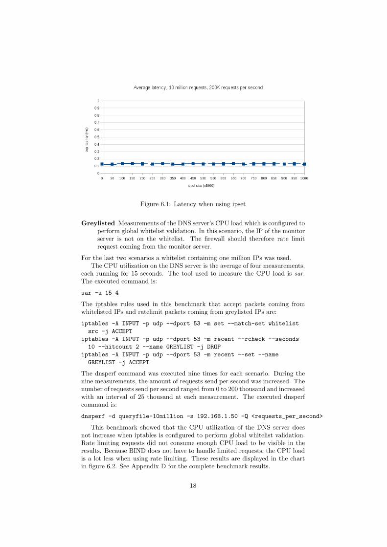
Figure 6.1: Latency when using ipset
Greylisted Measurements of the DNS server’s CPU load which is configured toperform global whitelist validation. In this scenario, the IP of the monitorserver is not on the whitelist. The firewall should therefore rate limitrequest coming from the monitor server.
For the last two scenarios a whitelist containing one million IPs was used.The CPU utilization on the DNS server is the average of four measurements,
each running for 15 seconds. The tool used to measure the CPU load is sar.The executed command is:
sar -u 15 4
The iptables rules used in this benchmark that accept packets coming fromwhitelisted IPs and ratelimit packets coming from greylisted IPs are:
iptables -A INPUT -p udp --dport 53 -m set --match-set whitelist
src -j ACCEPT
iptables -A INPUT -p udp --dport 53 -m recent --rcheck --seconds
10 --hitcount 2 --name GREYLIST -j DROP
iptables -A INPUT -p udp --dport 53 -m recent --set --name
GREYLIST -j ACCEPT
The dnsperf command was executed nine times for each scenario. During thenine measurements, the amount of requests send per second was increased. Thenumber of requests send per second ranged from 0 to 200 thousand and increasedwith an interval of 25 thousand at each measurement. The executed dnsperfcommand is:
dnsperf -d queryfile-10million -s 192.168.1.50 -Q <requests_per_second>
This benchmark showed that the CPU utilization of the DNS server doesnot increase when iptables is configured to perform global whitelist validation.Rate limiting requests did not consume enough CPU load to be visible in theresults. Because BIND does not have to handle limited requests, the CPU loadis a lot less when using rate limiting. These results are displayed in the chartin figure 6.2. See Appendix D for the complete benchmark results.
18

Figure 6.2: CPU load when using ipset
6.2.3 Whitelist manager
To simplify the implementation of global whitelist validation, the global whitelistmanagement tool is developed. This tool downloads the most recent list ofRRNS IPs and validates its integrity using md5 hashes. After downloading thelist an ipset is created and all downloaded IPs are added to the list. Finally thetools add the right rules to iptables. The tool is provided under the MIT licenseand is listed in Appendix E.
19

Chapter 7
Considerations and futurework
The feasibility of the practical approach depends on whether or not enoughRRNS servers can be collected by our custom ANS software. After all RRNSsare collected by means of crowd sourcing, the global whitelist validation can beapplied without negative impact.
For this research benchmarks were performed to measure the impact of val-idating global whitelists using iptables. Iptables is included in the Linux kerneland therefore not portable to different operation systems. Future research canbe done for performance benchmarks on firewall software that is used by differ-ent operating systems. Widely used firewall software for BSD based operatingsystems is PF 1. We do not see a reason to suspect worse performance whenusing different firewall software.
1http://www.openbsd.org/faq/pf/
20

Chapter 8
Conclusion
This research proposes to mitigate DNS Amplification Attacks by limiting DNSservices to intended users. Intended users for RRNSs are local users, intendedusers for ANSs are RRNSs.
Whitelists are needed to specify the intended users. Creating a whitelist fora RRNS is easy, since the local users are known by the network administrator.This paper proposes a method to generate a whitelist containing all global RRNSservers to be used by an ANS.
Applying a global whitelist can be done using standard firewall software.This research shows that there is no noticeable performance impact when ’ipt-ables’ is used for global whitelist validation. It is suggests that greylisting isapplied to ANS servers to allow for debugging.
To prove that the proposed solution mitigates DNS Amplification Attacks,all relevant attack scenarios are evaluated. This research also proves that theproposed solution is practically feasible, assuming enough RRNS servers can becollected.
21

Bibliography
[1] William Allen. improving tcp security with robust cookies.
[2] E Allman, J Callas, M Delany, M Libbey, J Fenton, and M Thomas. Do-mainkeys identified mail (dkim) signatures. Technical report, RFC 4871,May, 2007.
[3] Roy Arends, Rob Austein, Matt Larson, Dan Massey, and Scott Rose.Dns security introduction and requirements. Technical report, RFC 4033,March, 2005.
[4] J Damas and F Neves. Preventing use of recursive nameservers in reflectorattacks. Technical report, BCP 140, RFC 5358, October, 2008.
[5] L Donnerhacke. Dns dampening, september 2012.
[6] Homeland Security Federal Network Security. Domain name system (dns)security reference architecture. Technical report, 2011.
[7] Paul Ferguson. Network ingress filtering: Defeating denial of service attackswhich employ ip source address spoofing. 2000.
[8] Fanglu Guo, Jiawu Chen, and Tzi-cker Chiueh. Spoof detection for pre-venting dos attacks against dns servers. In Distributed Computing Systems,2006. ICDCS 2006. 26th IEEE International Conference on, pages 37–37.IEEE, 2006.
[9] Georgios Kambourakis, Tassos Moschos, Dimitris Geneiatakis, and Ste-fanos Gritzalis. A fair solution to dns amplification attacks. In DigitalForensics and Incident Analysis, 2007. WDFIA 2007. Second InternationalWorkshop on, pages 38–47. IEEE, 2007.
[10] Paul Mockapetris. Rfc 1034: Domain names-concepts and facilities. 1987.
[11] Paul Mockapetris. Rfc 1035: Domain names: implementation and specifi-cation. 1987.
[12] Jon Postel. Rfc 768: User datagram protocol. 1980.
[13] Jon Postel. Rfc 793: Transmission control protocol. 1981.
[14] Matthew Prince. The ddos that almost broke the internet. http://blog.cloudflare.com/the-ddos-that-almost-broke-the-internet, March2013.
22

[15] Matthew Prince. The ddos that knocked spamhaus offline(and how we mitigated it). http://blog.cloudflare.com/
the-ddos-that-knocked-spamhaus-offline-and-ho, March 2013.
[16] P Vixie. Dns response rate limiting (dns rrl), april 2012.
[17] Paul Vixie. Extension mechanisms for dns (edns0). 1999.
23
Appendix A
Pseudo-random IP listgeneration script
1 import random2
3 i p s= d i c t ( )4 for i in range (13000000) :5 i p s [ ’ . ’ . j o i n ( s t r ( random . rand int (1 ,255) ) for x in range
(4 ) ) ] = 16
7 print ” IPs generated , time to wr i t e ”8
9 i p f i l e = open ( ’ i p f i l e 1 0 m i l l i o n ’ , ’w ’ )10 for ip in i p s . keys ( ) :11 i p f i l e . wr i t e ( ”%s \n” % ip )12
13 print ”%d unique IPs added to f i l e ” % len ( i p s . keys ( ) )
24

Appendix B
Ipset whitelist generationscript
1 #!/ bin / bash2 for i in {0 . . 1 0 0 0 0 0 0 . . 5 0 0 0 0} ; do3 echo ‘ date ‘4 echo ” i p s e t c r e a t e w h i t e l i s t $ i hash : ip maxelem $ i ”5 ‘ i p s e t des t roy w h i t e l i s t $ i ‘6 ‘ i p s e t c r e a t e w h i t e l i s t $ i hash : ip maxelem $i ‘7 i p s =‘head −n $ i i p f i l e 1 0 m i l l i o n ‘ ;8 for ip in $ ip s ; do9 ‘ i p s e t add w h i t e l i s t $ i $ip ‘
10 done11 done
25

Appendix C
Latency benchmark results
# of entries in ipset Average latency over one million requests (in ms)0 0.129
50,000 0.126100,000 0.132150,000 0.133200,000 0.131250,000 0.128300,000 0.132350,000 0.127400,000 0.128450,000 0.132500,000 0.129550,000 0.129600,000 0.13650,000 0.133700,000 0.128750,000 0.13800,000 0.13850,000 0.13900,000 0.128950,000 0.13
1,000,000 0.127
26

Appendix D
CPU utilization benchmarkresults
CPU load CPU load CPU loadRequests per second no iptables requester whitelisted requester greylisted
0 0.06% 0.06% 0.06%25,000 12.11% 11.59% 0.06%50,000 23.14% 23.02% 0.06%75,000 26.63% 24.92% 0.06%100,000 36.03% 35.22% 0.06%125,000 44.37% 44.12% 0.06%150,000 54.36% 53.83% 0.06%175,000 60.9% 60.68% 0.06%200,000 67.49% 67.28% 0.06%
27

Appendix E
Global whitelistmanagement tool
1 #!/ usr / b in /python2 import commands3 import subproces s4 import u r l l i b5 import t a r f i l e6 import time7 import os8 import hash l i b9 import s h u t i l
10
11 def check requ i rements ( ) :12 i p s e t s t a t u s = commands . ge t s ta tusoutput ( ”hash i p s e t ” )13 i p t a b l e s s t a t u s = commands . ge t s ta tusoutput ( ”hash
i p t a b l e s ” )14 i f i p s e t s t a t u s [ 0 ] != 0 or i p t a b l e s s t a t u s [ 0 ] != 0 :15 raise Exception ( ” I p t a b l e s and/ or i p s e t not found ,
p l e a s e i n t s t a l l the se dependenc ies f i r s t ” )16
17 def m d 5 f o r f i l e ( f ) :18 md5 = hash l i b . md5( )19 for ip in f :20 md5 . update ( ip )21 return md5 . hexd ige s t ( )22
23 def r e t r i e v e w h i t e l i s t ( ) :24 w h i t e l i s t = u r l l i b . ur lopen ( ” http :// r e l i a b l e n a m e s e r v e r s .
org / w h i t e l i s t s / l a t e s t w h i t e l i s t ” )25 temp path = ”/tmp/ w h i t e l i s t/%d” % i n t ( time . time ( ) )26 temp name = os . path . j o i n ( temp path , ” l a t e s t w h i t e l i s t ” )27 os . makedirs ( temp path )28 temp = open ( temp name , ”wr” )29 temp . wr i t e ( w h i t e l i s t . read ( ) )
28

30 temp . f l u s h ( )31 temp . c l o s e ( )32
33 temp = open ( temp name )34 ta r = t a r f i l e . open (mode=” r : gz” , f i l e o b j=temp )35 ta r . e x t r a c t a l l ( temp path )36
37 l a t e s t w h i t e l i s t = open ( os . path . j o i n ( temp path , ”w h i t e l i s t ” ) , ” r ” )
38
39 i f m d 5 f o r f i l e ( l a t e s t w h i t e l i s t ) != open ( os . path . j o i n (temp path , ” w h i t e l i s t . md5” ) ) . read ( ) :
40 raise Exception ( ”Download seems to be corrupt , p l e a s erun again . ” )
41
42 return l a t e s t w h i t e l i s t43
44 def f i l l i p s e t ( l a t e s t w h i t e l i s t ) :45 subproces s . c a l l ( [ ” i p s e t ” , ” c r e a t e ” , ” w h i t e l i s t ” , ”hash :
ip ” , ”maxelem” , ”1000000” ] )46 l a t e s t w h i t e l i s t . seek (0 )47 for ip in l a t e s t w h i t e l i s t :48 subproces s . c a l l ( [ ” i p s e t ” , ”add” , ” w h i t e l i s t ” , ip ] )49
50 def a d d i p t a b l e s r u l e s ( ) :51 subproces s . c a l l ( ” i p t a b l e s −A INPUT −p udp −−dport 53 −m
s e t −−match−s e t w h i t e l i s t s r c −j ACCEPT” , s h e l l=True )
52 subproces s . c a l l ( ” i p t a b l e s −A INPUT −p udp −−dport 53 −mrecent −−rcheck −−seconds 10 −−h i tcount 2 −−name
GREYLIST −j DROP” , s h e l l=True )53 subproces s . c a l l ( ” i p t a b l e s −A INPUT −p udp −−dport 53 −m
recent −−s e t −−name GREYLIST −j ACCEPT” , s h e l l=True)
54
55 def cleanup ( ) :56 s h u t i l . rmtree ( temp path )57
58 i f name == ’ ma in ’ :59 print ” R e l i a b l e Nameserver i n s t a l l e r ”60 check requ i rements ( )61 print ”Download l a t e s t w h i t e l i s t ” ,62 l a t e s t w h i t e l i s t = r e t r i e v e w h i t e l i s t ( )63 print ” − Done”64 print ”Add w h i t e l i s t e d IPs to i p s e t ” ,65 f i l l i p s e t ( l a t e s t w h i t e l i s t )66 print ” − Done”67 i p t a b l e s = ””68 while i p t a b l e s . lower ( ) not in [ ”y” , ”n” ] :
29

69 i p t a b l e s = raw input ( ”Let i n s t a l l e r add i p t a b l e r u l e s? ( y/n) : ” )
70 i f i p t a b l e s . lower ( ) == ”y” :71 print ”Add i p t a b l e s r u l e s ” ,72 a d d i p t a b l e s r u l e s ( )73 print ” − Done”
30