Preventa machine safety guide - Schneider Electric · PDF fileMachines have to comply with the...
38
The essential guide Preventa machine safety helping you easily select the right product 2010
Transcript of Preventa machine safety guide - Schneider Electric · PDF fileMachines have to comply with the...

The essential guide Preventamachine safetyhelping you easilyselect the right product
2010

Why safety?
Human life is the most importantvalue in a company!
Schneider Electric protect people and improve your productivity.

Yourmachine
Riskassesment
analysis
Implemen-tation &
Certifi cation
Conception& Design
Maintennance /
Inspection& Audit
Preventa, the safety attitudearound your machine life cycleAs well as the moral obligation to avoid harming anyone, there are laws that require machines to be safe, and sound economic reasons for avoiding accidents.
Safety must be taken into account right from the design stage and must be kept in mind atall stages in the life of a machine: design, manufacture, installation, adjustment, operation, maintenance and eventual scrapping.
> New machines - the Machinery DirectiveThe Machinery Directive 98/37/EC is to compel manufacturers to guarantee a minimum safety level for machinery and equipment sold within the European Union.
From 29 December 2009, the new European Machinery Directive 2006/42/EC is effective. Machines have to comply with the Essential Health and Safety Requirements (EHSRs) listed in Annex I of the Directive, thus setting a common minimum level of protection across the EEA (European Economic Area).
Machine manufacturers, or their authorised representatives within the EU, must ensure that the machine is compliant, the Technical File can be made available to the enforcing authorities on request, the CE marking is affi xed, and a Declaration of Conformity has been signed, before the machine may be placed on the market within the EU.

Functional safety
«Helping you to reach easily your safety machinery and standard level required»
Thanks to directives and standards as guidelines.

EN/IEC 61508
SAFETY OF SYSTEMS AND EQUIPMENT
Functional safety of electrical / electronic /programmable electronic safety-related systems
EN/IEC 62061Machine safetyFunctional safety of control electrical / electronic /programmable electronic safety-related systems
EN/ISO 13849-1
Safety related parts of control systems
MACHINES
Risk reduction achieved by all safety-related systemsand external risk reduction facilities
Practical risk coveredby other technologysafety-relatedsystems
Practical risk coveredby electrical / electronic /programmable electronicsafety-related systems
Practical risk coveredby external riskreduction facilities
Necessary risk reduction
RESIDUALRISK
TOLERABLERISK
EQUIPMENT UNDERCONTROL RISK
Actual risk reduction
Functional safety> Safety integrity level (SIL), Performance level (PL)
Risk reduction according to EN/IEC 61508 and EN/ISO 13849-1
• Safety is achieved by risk reduction (for those hazards that cannot be designed-out).• Residual risk is the risk remaining after protective measures have been taken.• Protective measures realised by E/E/PE* safety related systems contribute to risk reduction.
* Electric / Electronic / Programmable electronic

Risk related tothe identifi edhazard
Severity ofthe possibleharm
FrPrAv
Probability ofoccurrence ofthat harm
Frequency and duration of exposureProbability of occurrence of a hazardous eventProbability of avoiding or limiting harm
Serial no.1
HazardHazard X
Se Fr5 + + =
Pr4
Av3
CI
2
Death, losing an eye or armPermanent, losing fingersReversible, medical attentionReversible, first aid
4321
SIL 23-4
SIL 25-7Class CI
FrFrequency and duration
OM<= 1 hour> 1 h to <= 1 day> 1 day to <= 2 wks2 wks to <= 1 year> 1 year
55432
PrProbability of hzd. Event
CommonLikelyPossibleRarelyNegligible
54321
AvAvoidance
ImpossiblePossibleLikely
531
SIL 2SIL 1OM
SIL 3SIL 2SIL 1OM
SIL 38-10 11-13 14-15
SIL 3SIL 2SIL 1
Consequences (Se)
Consequences
Reversible: requiring attention from a medical practitionerReversible: requiring first aid
Severity (Se)
321
Irreversible: broken limb(s), losing a finger(s)Irreversible: death, losing an eye or arm 4
4 12
Frequency and duration of exposure (Fr)
> 1 day to 2 weeks
5
4
1 h
> 2 weeks to 1 year 3> 1 year 2
Frequency of exposure > 10 min
> 1 h to 1 day 5
Probability of occurrence
Rarely
Probability (Pr)
2Negligible 1
Very high 5
Possible 34Likely
Probability of a voiding or limiting harm (Av)Impossible 5
1ProbableRarely 3
Safetyintegrity level(SIL)
321
>10-8 to <10-7
>10-7 to <10-6
>10-6 to <10-5
Probability of a dangerousFailure per HourPFHD
Functional safety of machinery> Approach according to EN/IEC 62061
Risk estimation for SIL assignment
Example of SIL assignment
This assignment should be carried by determining the risk parameters that are shown below in an example.
Determination of the SIL level achieved by the Safety-related control function (SRCF)
According to standard EN/IEC 62061 for each safety related control function, the SIL level is linked to:• a target failure value for the probability of dangerous failure by hour of the SRCF: PFHD• architectural constraints (hardware fault tolerance, diagnosis)• a set of requirements related to the lifecycle of the safety related electrical control system
λs= rate of safe failures,λdd= rate of detected dangerous failures, λdu= rate of undetected dangerous failuresλd = λdd +λdu
In practice, detected dangerous failure are dealt with by fault
• The rate of failures λ can be expressed as follows: λ= λs+ λdd +λdu
• The calculation of the PFHD for a systemor subsystem depends on several parameters:• the dangerous failure rate (λd) of the subsystem elements• the fault tolerance (e.g. redundancy) of the system• the diagnostic test interval (T2)• the proof test interval (T1) or lifetime whichever is smaller• the susceptibility to common cause failures (β)• For each of the four different logical architectures A to D there is adifferent formula to calculate the PFHD. (see EN/IEC 62061)• For a simple system without redondancy and without diagnostic:PFHD = λd x 1h
In this example the SIL 3 must be achieved by the safety-related control function intended to reduce the risk relatedto the identifi ed hazard.

Requiredperformancelevel PLr
Starting point forthe evaluation of thecontribution to therisk reduction of asafety function
Performancelevel (PL)
abcde
�10-5 ... < 10-4
�3 x 10⁻⁶ ... <10-5
�10-6…< 3 x 10⁻⁶
�10-7…< 10-6
�10-8…< 10-7
Probability of a dangerousFailure per Hour
Perf
orm
ance
leve
l “EN
/ ISO
1384
9-1”
Safe
ty In
tegr
ity Le
vel “
EN / I
EC 6
2061
”
Safety category level according to EN/ISO 13849-1
Cat. BDCavg =0
MTTFd of each channel = low
MTTFd of each channel = medium
MTTFd of each channel = high
Cat. 4DCavg =high
Cat. 3DCavg =medium
Cat. 3DCavg =low
Cat. 2DCavg =medium
Cat. 2DCavg =low
Cat. 1DCavg =low
Electromechanical componentsEmergency stop push-button Ø22 mm XB4 & XB5 (mushroom head)Emergency stop trip wire switches XY2 C Pushbutton Ø22 mm XB4 & XB5 Safety Limit switches with plunger or roller lever head XSCSafety switches with key (guard switches) XCSSafety switches with key (electromagnet guard switches) XCS Safety switches with rotary opening head XCS Safety coded magnetic switches XCS DMC/DMP/DMR at 10mA contactors with nominal loadcontactors with mechanical load
1 500 00050 00025 000 00050 000 0005 000 0005 000 0005 000 00050 000 0001 300 00020 000 000
B10d
> Approach according to EN/ISO 13849-1
Determination of the Performance Level requested (PLr)
This determination could be done using the risk graph.
S = Severity of injuryS1 = Slight (normally reversible injury)S2 = Serious (normally irreversible) injury including deathF = Frequency and/or exposure time to the hazardF1 = Seldom to less often and/or the exposure time is shortF2 = Frequent to continuous and/or the exposure time is longP = Possibility of avoiding the hazard or limiting the harmP1 = Possible under specifi c conditionsP2 = Scarcely possibleL = Low contribution to risk reductionH = High contribution to risk reduction
Determination of the PL achieved by theSafety-related parts of control systems (SRP/CS)
According to standard EN/ISO 13849-1,the Performance level (PL) is linked to a targetfailure value of probability of dangerous failureper hour for each safety related control function.
Functional safety and manufacturerreliability data of electromechanical components according toEN/ISO 13849-1 and EN/IEC 62061
Preventa, Harmony, Tesys -B10d values of electromechanical components.The following values apply to high or continuousdemand mode of operations used in machineryapplications. The B10d value is given to a lifetime of 20 years,but is mainly limited by mechinacal or contact wear.
For a SRP/CS (or a combination ofSRP/CS) designed according therequirements of the article 6, the PLcould be estimated with the fi gurebelow after estimation of severalfactors such as system structure(categories), mechanism of failuresdetection [Diagnosis Coverage (DC)],components reliability [mean time todangerous failure (MTTFd), CommonCause Failure (CCF)]…
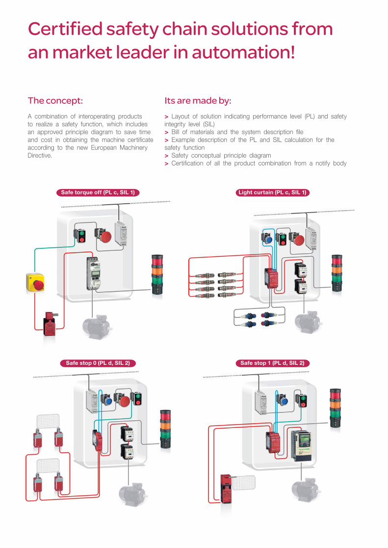
Certified safety chain solutions froman market leader in automation!
The concept:A combination of interoperating products to realize a safety function, which includes an approved principle diagram to save time and cost in obtaining the machine certificate according to the new European Machinery Directive.
Its are made by:> Layout of solution indicating performance level (PL) and safety integrity level (SIL)> Bill of materials and the system description file> Example description of the PL and SIL calculation for the safety function> Safety conceptual principle diagram> Certification of all the product combination from a notify body
Safe torque off (PL c, SIL 1) Light curtain (PL c, SIL 1)
Safe stop 0 (PL d, SIL 2) Safe stop 1 (PL d, SIL 2)

Be confident by using certified safety chainsolutions provided by an automation leader> Save cost by avoiding external safety experts engineering> Reduce design time by our examples of calculation of the safetylevel for each safety function
Safe Stop 1 (PL e, SIL 3) Safety Mat (PL d, SIL 2)
Magnetic switches (PL e, SIL 3) Zero speed detection (PL e, SIL 3)
Multifunction (PL e, SIL 3) AS-i safety (PL e, SIL 3)
ApprovedSafety chain solutions to achieve the safety level required

Safe signal transmission
Save cost and time with our Preventa offer...
Acquire the information:> Protective devices used as part of safeguarding systems to control the access under specifi c conditions of reduced risk. > Light curtains and safety mats to detect approachto dangerous and limited areas.
> Two hand control stations and enabling switchesfor starting and enabling of dangerous movements.
> Generic protective measures - Emergency stop.
Monitor and processing:> Safety relays modules with a specifi c safety function to monitor input signals from safety devices and to interface with contactors and drives by switch off the output safety contacts.
> Safety Controller: confi gurable safety device capable of centralized a generic range of safety monitoring functions.
> Safety PLCs: programmable electronic systems to carry out safety or non-safety related tasks for machi-nery and equipment.
> «As-i safety at work»: safety fi eld bus network certifi ed to work with safety devices to provide safety functions.
Safetyrelays
SafetyController
SafetyPLCs
As-i safetyat work
Protective devices
Safety mats Two hand control stationsand enabling switches
Emergency stop Tripwire switch
Light curtains

Stop the machine:> Contactors to cut-off the electrical power supply to the motors with mechanically linked mirror auxiliary contacts integrated for the feedback loop diagnosis of safety modules.
> Variable Speed Drives and Servodrives controlled stopping of the dangerous movement by safety power removal function integrated.
> Rotary switch disconnectors:for equipment isolation from the electrical supply and for emergency stop by direct interruption of the power supply.
VariableSpeed Drives
Rotary switchdisconnectors
ContactorsServodrives
1 Complete& upgradedsafety offer:Improve safety levelrequirement
Reduce installation timeby easy and quick wiring
Up to 50%of spaceoptimizationIncrease the compactnessby reducing size
Save upto 30%on installationtimeThanks to cage clamp,option included in our new products range
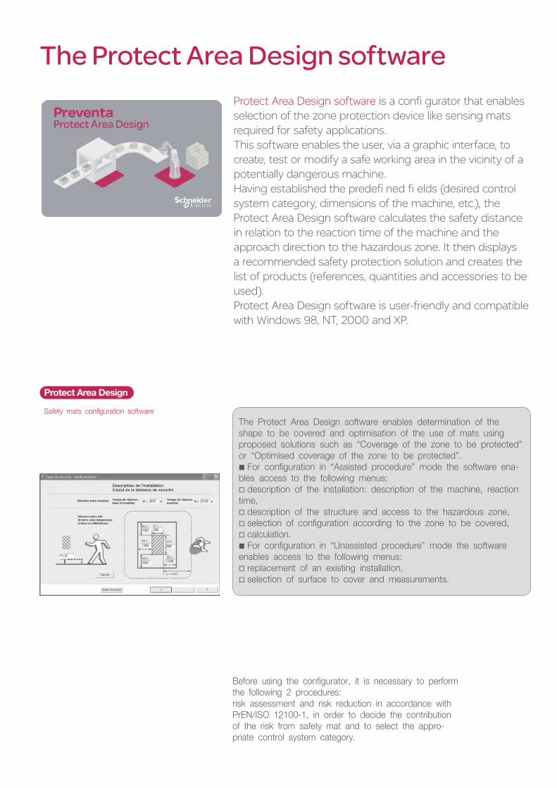
Protect Area Design software is a confi gurator that enables selection of the zone protection device like sensing mats required for safety applications.This software enables the user, via a graphic interface, to create, test or modify a safe working area in the vicinity of a potentially dangerous machine.Having established the predefi ned fi elds (desired control system category, dimensions of the machine, etc.), the Protect Area Design software calculates the safety distance in relation to the reaction time of the machine and the approach direction to the hazardous zone. It then displays a recommended safety protection solution and creates the list of products (references, quantities and accessories to be used).Protect Area Design software is user-friendly and compatible with Windows 98, NT, 2000 and XP.
Protect Area Design
Safety mats confi guration software
The Protect Area Design software enables determination of the shape to be covered and optimisation of the use of mats using proposed solutions such as “Coverage of the zone to be protected” or “Optimised coverage of the zone to be protected”.b For confi guration in “Assisted procedure” mode the software ena-bles access to the following menus:v description of the installation: description of the machine, reaction time,v description of the structure and access to the hazardous zone,v selection of confi guration according to the zone to be covered,v calculation.b For confi guration in “Unassisted procedure” mode the software enables access to the following menus:v replacement of an existing installation,v selection of surface to cover and measurements.
Before using the confi gurator, it is necessary to perform the following 2 procedures:risk assessment and risk reduction in accordance with PrEN/ISO 12100-1, in order to decide the contribution of the risk from safety mat and to select the appro-priate control system category.
The Protect Area Design software

WARNINGThis document is a selection of
the top selling products.
Machine safety
1
Automation ..................................................................................................................................................... 2 to 7
Safety PLCs Safety controllers and modules
AS-Interface Safety at work ............................................................................................................. 8 and 9
Safety monitors and interfaces
Detection ....................................................................................................................................................... 10 to 17
Safety switches Safety limit switches Coded magnetic technology Safety mats Safety light curtains
Operator dialogue .................................................................................................................................. 18 to 22
Emergency stops Foot switches Two-hand control and enabling switches
Motor control ............................................................................................................................................. 23 to 25
Switch disconnectors TeSys motor starters
Other versions: please consult your Schneider Electric agency.
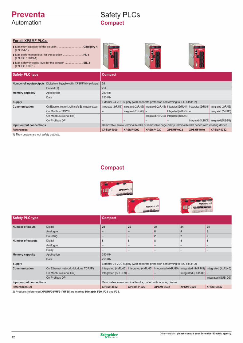
Safety PLC type Compact
Number of inputs/outputs Digital (confi gurable with XPSMFWIN software) 24Pulsed (1) 2x4
Memory capacity Application 250 Kb Data 250 Kb
Supply External 24 VDC supply (with separate protection conforming to IEC 61131-2)Communication On Ethernet network with safe Ethernet protocol Integrated (2xRJ45) Integrated (2xRJ45) Integrated (2xRJ45) Integrated (2xRJ45) Integrated (2xRJ45) Integrated (2xRJ45)
On Modbus TCP/IP – Integrated (2xRJ45) – Integrated (2xRJ45) – Integrated (2xRJ45)On Modbus (Serial link) – – Integrated (1xRJ45) Integrated (1xRJ45) – –On Profi bus DP – – – – Integrated (SUB-D9) Integrated (SUB-D9)
Input/output connections Removable screw terminal blocks or removable cage clamp terminal blocks coded with locating deviceReferences XPSMF4000 XPSMF4002 XPSMF4020 XPSMF4022 XPSMF4040 XPSMF4042
(1) They outputs are not safety outputs.
Compact
Safety PLC type Compact
Number of inputs Digital 20 20 24 24 24Analogue – – 8 8 8Counting – – 2 2 2
Number of outputs Digital 8 8 8 8 8Analogue – – – – –Relay – – – – –
Memory capacity Application 250 Kb Data 250 Kb
Supply External 24 VDC supply (with separate protection conforming to IEC 61131-2)Communication On Ethernet network (Modbus TCP/IP) Integrated (4xRJ45) Integrated (4xRJ45) Integrated (4xRJ45) Integrated (4xRJ45) Integrated (4xRJ45)
On Modbus (Serial link) Integrated (SUB-D9) – – Integrated (SUB-D9) –On Profi bus DP – – – – Integrated (SUB-D9)
Input/output connections Removable screw terminal blocks, coded with locating deviceReferences (2) XPSMF3022 XPSMF31222 XPSMF3502 XPSMF3522 XPSMF3542
(2) Products referenced XPSMF30/MF31/MF35 are marked Himatrix F30, F31 and F35.
Safety PLCsCompact
PreventaAutomation
For all XPSMF PLCs p Maximum category of the solution ..................................Category 4
(EN 954-1)p Max performance level for the solution ..........................PL e
(EN ISO 13849-1)p Max safety integrity level for the solution ........................SIL 3
(EN IEC 62061)
12

Other versions: please consult your Schneider Electric agency.
Type CPU Power supply module
Rack with 6 slots
Software
Memory capacity Application 500 Kb – – For XPSMF PLCsData 500 Kb – –
Supply – External 24 VDC, integrated –Communication On Ethernet network (Modbus TCP/IP) Integrated (4xRJ45) – – Complete version
On Modbus bus (Serial link) Integrated (SUB-D9) – – SSV1XPSMFWINPower connections Screw terminal blocks Screw terminal blocks – (1)Dimensions W x D x H – – 257 x 239 x 310 mm Update versionReferences XPSMFCPU22 XPSMFPS01 XPSMFGEH01 SSVXPSMFWINUP
I/O module type For modular safety PLCAnalogue Digital Relay
Number of inputs Digital – – – 24 32 24 –Analogue 8 – – – – – –Counting – – 2 – – – –
Number of outputs Digital – – 4 – – 16 –Analogue – 8 – – – – –Relay – – – – – – 8
Supply Removable screw terminal blocks, coded with locating deviceReferences XPSMFAI801 XPSMFAO801 XPSMFCIO2401 XPSMFDI2401 XPSMFDI3201 XPSMFDIO241601 XPSMFDO801
Decentralised safety I/O modules
Module type Inputs/OuputsDigital
Number of inputs Digital 16 8+2 16 20Number of outputs Digital – 8 8 8
Pulsed 4 2 2 –Supply External 24 VDC supply (with separate protection conforming to IEC 61131-2)Communication On Safe Ethernet network (Modbus TCP/IP) Integrated (2xRJ45)Input/output connections Removable screw terminal blocks, coded with locating deviceReferences (2) XPSMF1DI1601 XPSMF3DIO8801 XPSMF3DIO16801 XPSMF3DIO20802
I/O module type Inputs/OutputsAnalogue
OutputsDigital Relay
Number of inputs Analogue 8 – – – –Number of outputs Digital – 4 16 – –
Analogue (not safety) 4 – – – –Relay – – – 8 16
Supply External 24 VDC supply (with separate protection conforming to IEC 61131-2)Communication On Safe Ethernet network (Modbus TCP/IP) Integrated (2xRJ45)Input/output connections Removable screw terminal blocks, coded with locating deviceReferences (2) XPSMF3AIO8401 XPSMF2DO401 XPSMF2DO1601 XPSMF2DO801 XPSMF2DO1602
(1) To be ordered only if the previous version of have been already installed.(2) Products referenced XPSMF1/MF2/MF3 are marked Himatrix F1, F2 and F3.
For all XPSMF PLCs p Maximum category of the solution ..................................Category 4
(EN 954-1)p Max performance level for the solution ..........................PL e
(EN ISO 13849-1)p Max safety integrity level for the solution ........................SIL 3
(EN IEC 62061)
13

Other versions: please consult your Schneider Electric agency.
Universal
Universal
Universal
PreventaAutomation
Safety controllers for monitoringemergency stops and limit switches
Maximum safety level of the solution attained (EN ISO 13849-1, EN/IEC 62061)
PL e / Cat. 4, SILCL 3
Number of circuits Safety 2 x 2N/O + 6 solid-state 2 x 3N/O per functionAdditional – 3 solid-state
Display (number of LEDs) 30 12Width of housing 74 mm 45 mmCommunication interface Modbus Modbus, CANopen Modbus, Profi bus DP –
Universal solutions: safety controllers (for monitoring several safety functions simultaneously)Supply voltage 24 VDC XPSMC32Z (1) (2) XPSMC32ZC (1) (2) XPSMC32ZP (1) (2) XPSMP11123P (3)
coded magnetic switchesenabling switch
Maximum safety level of the solution attained (EN ISO 13849-1, EN/IEC 62061)
PL e / Cat. 4, SILCL 3
For monitoring magnetic switches and enabling switchNumber of circuits Safety 2 x 2N/O + 6 solid-state 2 x 3N/O per function
Additional – 3 solid-stateDisplay (number of LEDs) 30 12Width of housing 74 mm 45 mmCommunication interface Modbus Modbus, CANopen Modbus, Profi bus DP –
Universal solutions: safety controllers (for monitoring several safety functions simultaneously)Supply voltage 24 VDC XPSMC32Z (1)(2) XPSMC32ZC (1)(2) XPSMC32ZP (1)(2) XPSMP11123P (3)
safety mats and edging
Maximum safety level of the solution attained (EN ISO 13849-1, EN/IEC 62061)
PL d / Cat. 3, SILCL 2
Number of circuits Safety 2 x 2N/O + 6 solid-state 2 x 3N/O per functionAdditional – 3 solid-state
Display (number of LEDs) 30 12Width of housing 74 mm 45 mmCommunication interface Modbus Modbus, CANopen Modbus, Profi bus DP –
Universal solutions: safety controllers (for monitoring several safety functions simultaneously)Supply voltage 24 VDC XPSMC32Z (1)(2) XPSMC32ZC (1)(2) XPSMC32ZP (1)(2) XPSMP11123P (3)
(1) Version with 32 inputs. For version with 16 inputs, replace 32 in the reference by 16 (example: XPSMC32Z becomes XPSMC16Z).(2) Confi guration software XPSMCWIN (complete version) or SSVXPSMCWINUP (update version), connecting cable, adaptor and set of screw terminal plug-in connectors XPSMCTS16 and XPSMCTS32 or set of spring clip terminal plug-in connectors XPSMCTC16 and XPSMCTC32 to be ordered separately.(3) For fi xed connector version, delete the letter P from the end of the reference (example: XPSMP11123P becomes XPSMP11123).
14

Other versions: please consult your Schneider Electric agency.
Safety modules for monitoringemergency stops and limit switches
Maximum safety level of the solution attained (EN ISO 13849-1, EN/IEC 62061)
PL e / Cat. 4, SILCL 3
Number of circuits Safety 3 N/O 3N/O 3 N/O 3 N/O 7 N/O 3N/O + 3N/O time del.
2N/O + 1N/O time del.
2N/O + 3N/O time del.
Additional 1 solid-state 1 N/C – 1 N/C + 4 solid-state
2 N/C + 4 solid-state
3 solid-state – 4 solid-state
Display (number of LEDs) 2 2 3 4 4 11 3 4Width of housing 22.5 mm 22.5 mm 22.5 mm 45 mm 90 mm 45 mm 22.5 mm 45 mm
Optimum solutions: safety modules (for monitoring 1 safety function)Supply voltage (1) 24 VDC – – – – XPSAV11113P XPSABV11330P (2) –
24 VAC/DC XPSAC5121P XPSAXE5120P (2) XPSAF5130P XPSAK311144P XPSAR311144P – – XPSATE5110P230 VAC – – – – – – – XPSATE3710P
(1) For version with non removable terminal block, delete the letter P from the end of the reference (example: XPSAV11113P becomes XPSAV11113).(2) For version with cage clamps removable terminal block, change the letter P for C from the end of the reference (example: XPSAXE5120P becomes XPSAXE5120C)
coded magnetic switchesenabling switch
Maximum safety level of the solution attained (EN ISO 13849-1, EN/IEC 62061)
PL e / Cat. 4, SILCL 3
For monitoring 2 coded magnetic 6 coded magnetic enabling switchswitches maximum switches maximum
Number of circuits Safety 2N/O 2N/O 2N/OAdditional 2 solid-state 2 solid-state 2 solid-state
Display (number of LEDs) 3 15 3Width of housing 22.5 mm 45 mm 22.5 mm
Optimum solutions: safety modules (for monitoring 1 safety function)Supply voltage 24 VDC XPSDMB1132P (1) XPSDME1132P (1) XPSVC1132P (1)
(1) For version with non removable terminal block, delete the letter P from the end of the reference (example: XPSDMB1132P becomes XPSDMB1132).
safety mats and edging
Maximum safety level of the solution attained (EN ISO 13849-1, EN/IEC 62061)
PL d / Cat. 3, SILCL 2
Number of circuits Safety 3N/OAdditional 1N/C + 4 solid-state
Display (number of LEDs) 4Width of housing 45 mm
Optimum solutions: safety modules (for monitoring 1 safety function)Supply voltage 24 VAC/DC XPSAK311144P (1)
(1) For version with non removable terminal block, delete the letter P from the end of the reference (example: XPSAK311144P becomes XPSAK311144).
New New
15

Other versions: please consult your Schneider Electric agency.
0,0
0,2
0,4
0,6
0,8
1,0
0,0
0,2
0,4
0,6
0,8
1,0
Universal
Universal
Universal
PreventaAutomation
Safety controllers for monitoringtwo-hand control
Maximum safety level of the solution attained (EN ISO 13849-1, EN/IEC 62061)
PL e / Cat. 4, SILCL 3
Number of circuits Safety 2 x 2N/O + 6 solid-stateAdditional –
Display (number of LEDs) 30Width of housing 74 mmCommunication interface Modbus Modbus, CANopen Modbus, Profi bus DP
Universal solutions: safety controllers (for monitoring several safety functions simultaneously)Supply voltage 24 VDC XPSMC32Z (1)(2) XPSMC32ZC (1)(2) XPSMC32ZP (1)(2)
light curtains
Maximum safety level of the solution attained (EN ISO 13849-1, EN/IEC 62061)
PL e / Cat. 4, SILCL 3 2 light curtainsmonitoring max.
Number of circuits Safety 2 x 2N/O + 6 solid-state 2x3N/O per function 6 PNP solid-stateAdditional – 3 solid-state 1 PNP + 1 NPN
Display (number of LEDs) 30 12 14 + double display unitsWidth of housing 74 mm 45 mm 100 mmIntegral Muting function Yes No YesCommunication interface Modbus Modbus, CANopen Modbus, Profi bus DP – –
Universal solutions: safety controllers (for monitoring several safety functions simultaneously)Supply voltage 24 VDC XPSMC32Z(1)(2) XPSMC32ZC(1)(2) XPSMC32ZP(1)(2) XPSMP11123P (3) XPSLCM1150 (4)
(1) Version with 32 inputs, for version with 16 inputs, replace 32 in the reference by 16 (example: XPSMC32Z becomes XPSMC16Z).(3) For version with non removable terminal block, delete the letter P from the end of the reference (example: XPSMP11123P becomes XPSMP11123).(4) Removable terminal blocks
zero speed, time delay
Maximum safety level of the solution attained (EN ISO 13849-1, EN/IEC 62061)
PL e / Cat. 4, SILCL 3
For monitoring Motor zero speed conditionNumber of circuits Safety 2 x 2N/O + 6 solid-state
Additional –Display (number of LEDs) 30Width of housing 74 mmCommunication interface Modbus Modbus, CANopen Modbus, Profi bus DP
Universal solutions: safety controllers (for monitoring several safety functions simultaneously)Supply voltage 24 VDC XPSMC32Z (5) (2) XPSMC32ZC (5) (2) XPSMC32ZP (5) (2)
(2) Confi guration software XPSMCWIN (complete version) or SSVXPSMCWINUP (update version), connecting cable, adaptor and set of screw terminal plug-in connectors XPSMCTS16 and XPSMCTS32 or set of spring clip terminal plug-in connectors XPSMCTC16 and XPSMCTC32 to be ordered separately.(5) Plug-in connector version only.
16

Other versions: please consult your Schneider Electric agency.
0,0
0,2
0,4
0,6
0,8
1,0
Safety modules for monitoringtwo-hand control
Maximum safety level of the solution attained (EN ISO 13849-1, EN/IEC 62061)
PL c / Cat. 1 PL e / Cat. 4, SILCL 3(type IIIA to EN 574/ISO 13851) (type IIIC to EN 574/ISO 13851)
Number of circuits Safety 1N/O 2N/O 2N/OAdditional 1N/C 1N/C 2 solid-state
Display (number of LEDs) 2 3 3Width of housing 22.5 mm 22.5 mm 22.5 mm
Optimum solutions: safety modules (for monitoring 1 safety function)Supply voltage 24 VDC – – XPSBF1132P (1)
24 VAC/DC XPSBA5120 XPSBCE3110P (2) –(1) For version with non removable terminal block, delete the letter P from the end of the reference (example: XPSBF1132P becomes XPSBF1132).(2) For version with cage clamps removable terminal block, change the letter P for C from the end of the reference (example: XPSBCE3110P becomes XPSBCE3110C)
light curtains
Maximum safety level of the solution attained (EN ISO 13849-1, EN/IEC 62061)
PL c / Cat. 2, SILCL 1 PL e / Cat. 4, SILCL 3
Number of circuits Safety 2N/O 3N/O 3N/O 7N/OAdditional 4 solid-state – 1N/C + 4 solid-state 1N/C + 4 solid-state
Display (number of LEDs) 4 3 4 4Width of housing 45 mm 22.5 mm 45 mm 90 mmIntegral Muting function Yes No No No
Optimum solutions: safety modules (for monitoring 1 safety function)Supply voltage 24 VDC XPSCM1144P (1) – – –
24 VAC/DC – XPSAFL5130P (1) XPSAK311144P (1) XPSAR311144P (1)(1) For version with non removable terminal block, delete the letter P from the end of the reference (example: XPSCM1144P becomes XPSCM1144).
zero speed, time delay and lifts
Maximum safety level of the solution attained (EN ISO 13849-1, EN/IEC 62061)
PL d / Cat. 3, SILCL 2 PL e / Cat. 4, SILCL 3
For monitoring Motor zero speed condition Safety time delay LiftsNumber of circuits Safety 1N/O + 1N/C 1N/O time delay 1N/O pulse 2N/O
Additional 2 solid-state 2N/C + 2 solid-state 2N/C + 2 solid-state 2 solid-stateDisplay (number of LEDs) 4 4 4 4Width of housing 45 mm 45 mm 45 mm 22.5 mm
Optimum solutions: safety modules (for monitoring 1 safety function)Supply voltage 24 VDC XPSVNE1142P (1) – – –
24 VAC/DC – XPSTSA5142P (2) XPSTSW5142P (2) XPSEDA5142(1) Motor frequency ≤ 60 Hz.. For frequencies ≥ 60 Hz, please refer to the “Safety solution” catalogue.(2) Removable terminal block version only.
New
New
17

Other versions: please consult your Schneider Electric agency.
PreventaAS-Interface safety at work
Safety monitorsMonitors
Confi guration software, adjustment terminal and AS-Interface analyser
Maximum safety level of the solution attained (EN ISO 13849-1, EN/IEC 62061)
PL e / Cat. 4, SILCL 3
Number of circuits Safety 2N/O 2 x 2N/OAuxiliary 1 solid-state 2 solid-state
Display (number of LEDs) 5 8Width of housing 45 mm 45 mmAS-Interface profi le S.7.F S.7.FMaster module compatibility V1 / V2.1 V1 / V2.1References of monitor with enhanced functions ASISAFEMON1B ASISAFEMON2B
standard functions ASISAFEMON1 ASISAFEMON2
(1) CD-ROM with hardware and software user guides.(2) For addressing safety interfaces, use the infrared adaptor ASITERIR1 or the standard adaptor ASISAD1.(3) To be ordered only if a previous version of ASISWIN have been already installed.
Accessories
Type Adaptorfor the adressingof safety interfaces
Infrared adaptorfor adjustment terminal
Tap-offfor AS-Interface cable
Cablefor monitor
parametering, RS 232
Cablefor monitor to monitor
transferDegree of protection – IP 67 IP 67 IP 20 IP 20Cable length – 1 m 2 m 2 m 0.2 mReferences ASISAD1 ASITERIR1 TCSATN01N2 ASISCPC ASISCM
Type Confi guration software (1) Adjustment terminal (2) AS-Interface Analyser
Multilingual EN / FR / DE / ES / IT / PT – b Analysis and diagnostics of AS-InterfaceFor use with ASISAFEMON1/2, – line and Safety at Work
ASISAFEMON1B/2B b Complements the diagnostic functions ofMedia CD-ROM PC – the local AS-Interface masterEnvironment Windows – b Maintenance or validation of AS-InterfaceDegree of protection – IP 40 lines Supply – 4 x LR6 batteries b Print-out of AS-Interface line testsDimensions W x D x H – 70 x 50 x 170 mm 92 x 28 x 139 mmReferences Complete version ASISWIN2 ASITERV2 ASISA01
Update version (3) SSVASISWINUP – –
18

Other versions: please consult your Schneider Electric agency.
Accessories
(6) For connection using 2 pre-wired connectors, or 1 pre-wired connector + 1 connector.(7) For 1 x ISO M20 entry, use adaptor shown below.
Type of entry 2 x M12 entries (6) 1 x M12 entry 1 x ISO M16 entry (7)
Degree of protection IP 67 IP 67 IP 67Dimensions W x D x H 40 x 40 x 58 mm 40 x 40 x 58 mm 40 x 40 x 57.5 mmAS-Interface profi le S.0.B.F.F S.0.B.F.F S.0.B.F.FConsumption from AS-Interface 45 mA 45 mA 45 mAInfrared addressing Yes Yes YesConnection on AS-Interface IDC (1) IDC (1) IDC (1)References ASISSLC2 ASISSLC1 ASISSLLS
Safety interfacesFor Ø 22 Emergency stop
Interface type For mushroom head pushbuttons Control stationsMetal (1) Plastic (1) Plastic
Degree of protection IP 20 IP 20 IP 20 IP 20 IP 65 IP 65Dimensions W x D x H (mm) 40 x 90 x 68 40 x 80 x 40 40 x 90 x 64 40 x 90 x 40 66 x 95 x 78 66 x 95 x 78AS-Interface profi le S.0.B.F.F S.0.B.F.F S.0.B.F.F S.0.B.F.F S.0.B.F.F S.0.B.F.FConsumption from AS-Interface 45 mA 45 mA 45 mA 45 mA 45 mA 45 mAInfrared addressing Yes No Yes No No NoConnection on AS-Interface IDC (2) Connector IDC (2) Connector M12 connector M12 connectorReference with N/C + N/C contact (head not included) ASISSLB4 ASISSLE4 ASISSLB5 ASISSLE5 ASISEA1C ASISEK1CReference of head (Ø40 latching mushroom head, turn to release) ZB4BS844 (3) ZB4BS844 (3) ZB4AS844 (3) ZB5AS844 (3) Integrated (4) Integrated (5)
(1) For installation in enclosures.(2) IDC: Insulation Displacement Connector.(3) Head to be ordered separately. For other heads, please refer to www.schneider-electric.com.(4) Turn to release latching mushroom head.(5) Key release (n° 455) latching mushroom head.
For other safety products withM12 connector outputs or ISO M16/20
Type Tap-off forAS-Interface cable
Connectors Pre-wiredconnector
Adaptor(sold in lots of 5)
Description M12 female, threaded elbowed straight straight ISO M16/M20Degree of protection IP 67 IP 67 IP 67 IP 67 IP 67Length of cable – – – 2 m –References TCSATN011F XZCC12MCM40B XZCC12MDM40B XZCP1541L2 DE9RI2016
19

Other versions: please consult your Schneider Electric agency.
20/2220/22
60
30
60
30
20/2220/22
30
153.
320/2240,3
30
153.
3
30
153.
3
2-pole contactSlow break(N/C + N/O)
2-pole contactSlow break(N/C + N/C)
3-pole contactSlow break(N/C + N/O + N/O)
3-pole contactSlow break(N/C + N/C + N/O)
PreventaDetection
Safety switchesand actuators
Plastic, double insulated switches Type XCSMP Type XCSPA and TA Type XCSLEpre-cabled, L = 2 m 1xISO M16 entry. (2) 2xISO M16 entries. (2) 3 x ISO M20 cable entries
Actuation speed (min → max) 0,05 m/s → 1,5 m/s 0,1 m/s → 0,5 m/s 0,1 m/s → 0,5 m/sDegree of protection IP 67 IP 67 IP 67 + IP 66Rated operational characteristics (conforming to EN IEC 60947-5-1) AC 15, C 300 / DC 13, Q 300 AC 15, A 300 / DC 13, Q 300 AC 15, B 300 / DC 13, Q 300Dimensions (body + head) W x D x H 30 x 15 x 87 mm 30 x 30 x 93,5 mm 52 x 30 x 114,5 mm 43,6 x 205 x 50,6 mmSolenoid supply voltage – – – 24 VAC/DCComplete switch N/C+N/O N/O stag. slow break XCSMP59L2 (3) XCSPA592 – XCSLE2525312
N/C+N/C slow break XCSMP79L2 (3) XCSPA792 – XCSLE2727312
N/C+N/O+N/O 2 N/O stag. slow break XCSMP70L2 (3) XCSPA892 XCSTA592 XCSLE3535312N/C+N/O+N/O snap action – – – –
N/C+N/C+N/O N/O stag. slow break XCSMP80L2 (3) XCSPA992 XCSTA792 XCSLE3737312N/C+N/C+N/O snap action – XCSPA492 – –
Without lockingLocking on de-energisation of solenoid (1)
3-pole contactSlow break(N/C + N/O + N/O)
3-pole contactSlow break(N/C + N/C + N/O) Without locking With interlocking, manual unlocking
By button By key lockLocking on de-energisationof solenoid (1)
(1) For locking on energisation of solenoid, please refer to www.schneider-electric.com.(2) With entry for n° 11 (Pg 11) cable gland, replace the last digit in the reference by 1 (example: XCSPA592 becomes XCSPA591).(3) For other models, please refer to www.schneider-electric.com.
Metal switches Type XCSA/B/C1 x ISO M20 cable entry (2)
Type XCSLF3 x ISO M20 cable entries
Actuation speed (min → max) 0.1 m/s → 0.5 m/s 0.1 m/s → 0.5 m/sDegree of protection IP 67 IP 67 + IP 66Rated operational characteristics (conforming to EN IEC 60947-5-1) AC 15, A 300 / DC 13, Q 300 AC 15, B 300 / DC 13, Q 300Dimensions (body + head) W x D x H 40 x 44 x 113.5 mm 52 x 44 x 113.5 mm 52 x 44 x 113.5 mm 43,6 x 205 x 50,6 mmSolenoid supply voltage – – – 24 VAC/DC 24 VAC/DCComplete switch N/C+N/O+N/O 2 N/O stag. slow break XCSA502 XCSB502 XCSC502 XCSLF3535312 XCSLF3535412
N/C+N/C+N/O N/O stag. slow break XCSA702 XCSB702 XCSC702 XCSLF3737312 XCSLF3535412
N/C+N/O N/O stag. slow break XCSLF2525312N/C+N/C snap break XCSLF2727312
(1) For locking on energisation of solenoid, please refer to www.schneider-electric.com.(2) With entry for n° 13 (Pg 13.5) cable gland, replace the last digit in the reference by 1 (example: XCSA502 becomes XCSA501).
Accessories
Straight actuator Wide actuator L=40 mm (1) Right-angled actuator Pivoting actuator
Straight actuator Right-angled actuator Pivoting actuator, RH door Pivoting actuator, LH door
Guard/door retainer
Straight actuator Wide actuator Pivoting actuator
ISO entry(to EN 50262)
ISO entry(to EN 50262)
1314 22
21
1112 22
21
1314 22
21
1112 22
21
For safety switches XCSMP ActuatorsReferences XCSZ81 XCSZ84 XCSZ83 XCSZ85
For safety switches XCSPA/TA/TE Actuators Retaining deviceReferences XCSZ11 XCSZ12 XCSZ14 XCSZ13 XCSZ21
For safety switches XCSA/B/C/LE/LF Actuators Door lockReferences XCSZ01 XCSZ02 XCSZ03 XCSZ05
(1) For L = 29 mm, reference = XCSZ15.
20
Other versions: please consult your Schneider Electric agency.
20/2220/22
20/2240,3
20/2240,3
2-pole contactSlow break(N/C + N/O)
2-pole contactSlow break(N/C + N/C)
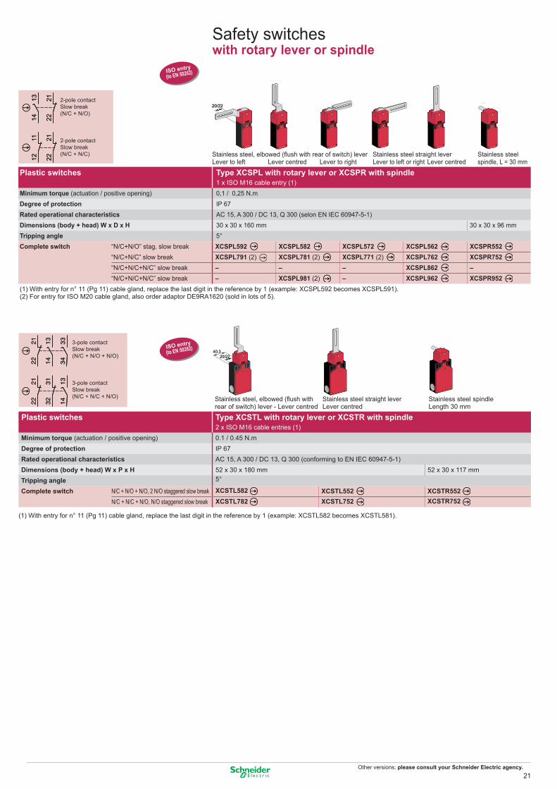
Safety switcheswith rotary lever or spindle
Stainless steel, elbowed (fl ush with rear of switch) lever Stainless steel straight lever Stainless steelLever to left Lever centred Lever to right Lever to left or right Lever centred spindle, L = 30 mm
Plastic switches Type XCSPL with rotary lever or XCSPR with spindle1 x ISO M16 cable entry (1)
Minimum torque (actuation / positive opening) 0,1 / 0,25 N.mDegree of protection IP 67Rated operational characteristics AC 15, A 300 / DC 13, Q 300 (selon EN IEC 60947-5-1)Dimensions (body + head) W x D x H 30 x 30 x 160 mm 30 x 30 x 96 mmTripping angle 5°Complete switch “N/C+N/O” stag. slow break XCSPL592 XCSPL582 XCSPL572 XCSPL562 XCSPR552
“N/C+N/C” slow break XCSPL791 (2) XCSPL781 (2) XCSPL771 (2) XCSPL762 XCSPR752 “N/C+N/C+N/C” slow break – – – XCSPL862 –“N/C+N/C+N/C” slow break – XCSPL981 (2) – XCSPL962 XCSPR952
3-pole contactSlow break(N/C + N/O + N/O)
3-pole contactSlow break(N/C + N/C + N/O) Stainless steel, elbowed (fl ush with Stainless steel straight lever Stainless steel spindle
rear of switch) lever - Lever centred Lever centred Length 30 mm
Plastic switches Type XCSTL with rotary lever or XCSTR with spindle2 x ISO M16 cable entries (1)
Minimum torque (actuation / positive opening) 0.1 / 0.45 N.mDegree of protection IP 67Rated operational characteristics AC 15, A 300 / DC 13, Q 300 (conforming to EN IEC 60947-5-1)Dimensions (body + head) W x P x H 52 x 30 x 180 mm 52 x 30 x 117 mmTripping angle 5°
Complete switch N/C + N/O + N/O, 2 N/O staggered slow break XCSTL582 XCSTL552 XCSTR552
N/C + N/C + N/O, N/O staggered slow break XCSTL782 XCSTL752 XCSTR752
(1) With entry for n° 11 (Pg 11) cable gland, replace the last digit in the reference by 1 (example: XCSPL592 becomes XCSPL591).(2) For entry for ISO M20 cable gland, also order adaptor DE9RA1620 (sold in lots of 5).
(1) With entry for n° 11 (Pg 11) cable gland, replace the last digit in the reference by 1 (example: XCSTL582 becomes XCSTL581).
ISO entry(to EN 50262)
ISO entry(to EN 50262)
1314 22
21
1112 22
21
1314 22
21
1112 22
21
21

Other versions: please consult your Schneider Electric agency.
RD-W
HR
D BUBN
GN-YE
BK-W
HBK
RD-W
HR
D BUBN
GN-YE
BK-W
HBK
RD-W
HR
D BUBN
GN-YE
BK-W
HBK
RD-W
HR
D BUBN
GN-YE
BK-W
HBK
PreventaDetection
Limit switchesSafety limit switches
3-pole contactN/C + N/C + N/OSlow break
3-pole contactN/C + N/C + N/OSnap action
3-pole contactN/C + N/C + N/OSlow break
3-pole contactN/C + N/C + N/OSnap action
Metal Roller plunger Thermoplasticend plunger roller lever
Metal Roller Thermoplastic Metal Roller Thermoplasticend plunger plunger roller lever end plunger plunger roller lever
Miniature switches Type XCSM, metalpre-cabled, L = 1 m (1)
Maximum actuation speed 0.5 m/s 0.5 m/s 1.5 m/sMinimum force or torque (actuation / positive opening) 8.5 N / 42.5 N 7 N / 35 N 0.5 N.m / 0.1 N.mDegree of protection IP 66 + IP 67 + IP 68 IP 66 + IP 67 + IP 68 IP 66 + IP 67 + IP 68Dimensions (body + head) W x D x H 30 x 16 x 60 mm 30 x 16 x 70.5 mm 30 x 32 x 92.5 mmComplete switch N/C + N/C + N/O snap action XCSM3910L1 XCSM3902L1 XCSM3915L1
N/C + N/C + N/O slow break XCSM3710L1 XCSM3702L1 XCSM3715L1
(1) For a 2 m long cable, replace the last digit of the reference by 2 (example: XCSM3910L1 becomes XCSM3910L2).For a 5 m long cable, replace the last digit of the reference by 5 (example: XCSM3910L1 becomes XCSM3910L5).
Compact switches Type XCSD, metal Type XCSP, plastic1 x ISO M20 x 1.5 cable entry (2) 1 x ISO M20 x 1.5 cable entry (2)
Maximum actuation speed 0.5 m/s 1.5 m/s 0.5 m/s 1.5 m/sMinimum force or torque (actuation / positive opening) 15 N / 45 N 12 N / 36 N 10 N.m / 0.1 N.m 15 N / 45 N 12 N / 36 N 10 N.m / 0.1 N.mDegree of protection IP 66 + IP 67 IP 66 + IP 67Dimensions (body + head) W x D x H (mm) 34 x 34.5 x 89 34 x 34.5 x 99.5 34 x 43 x 121.5 34 x 34.5 x 89 34 x 34.5 x 99.5 34 x 43 x 121.5Complete switch N/C + N/C + N/O snap action XCSD3910P20 XCSD3902P20 XCSD3918P20 XCSP3910P20 XCSP3902P20 XCSP3918P20
N/C + N/C + N/O slow break XCSD3710P20 XCSD3702P20 XCSD3718P20 XCSP3710P20 XCSP3702P20 XCSP3718P20(2) For Pg 13.5 and 1/2" NPT cable entries, refer to www.schneider-electric.com.
22

Other versions: please consult your Schneider Electric agency.
1/BN
NO
NO
I1
I2
O1
O2
7/GY
4/BK
6/PK
2/WH
3/BU
K1K2
+
+
+
– 1
76 4
3
2
F1
2 A
1/BN
NO
NO
I1
I2O1
O2
7/VTEr5/GY
4/BK6/PK
2/WH
3/BU
K1K2
K1K2
+
+
+
–8/OG
+Diag
1
76 4
5
3
28
+
F1
2 A
Contact (N/C + N/O,N/Cstaggered)
Contact (N/O + N/O,1N/O staggered)
Contact (N/C + N/C + N/O, 1N/C staggered)
Contact (N/C + N/O + N/O, 1N/O staggered)
(1) (1)
BK BU
WH BN
BK BU
WH BN
BK BU
WH BN
BK BU
WH BN
PKG
Y
BKW
H
BUBN
PKG
Y
BKW
H
BUBN
PKG
Y
BKW
H
BUBN
PKG
Y
BKW
H
BUBN
Rectangular Rectangular Cylindrical Rectangular Rectangular CylindricalWithout LED (2) Without LED (2) Without LED (2) Without LED (2) Without LED (2) Without LED (2)
Coded magnetic
Plastic switches Type XCSDM coded magneticPre-cabled, L = 2 m Connector on fl ying lead, L = 10 cm (3)
Switches for actuation Face to face, face to side, side to side Face to face Face to face, face to side, side to side Face to faceDegree of protection IP 66 + IP 67 IP 66 + IP 67Type of contact REED REEDRated operational characteristics Ue = 24 VDC, Ie = 100 mA Ue = 24 VDC, Ie = 100 mADimensions W x D x H 16 x 7 x 51 mm 25 x 13 x 88 mm M30 x 38,5 mm 16 x 7 x 51 mm 25 x 13 x 88 mm M30 x 38.5 mmOperating zone (4) Sao = 5 / Sar = 15 Sao = 8 / Sar = 20 Sao = 5 / Sar = 15 Sao = 8 / Sar = 20Switch with coded magnet N/C + N/O, N/C staggered XCSDMC5902 XCSDMP5902 XCSDMR5902 XCSDMC590L01M8 XCSDMP590L01M12 XCSDMR590L01M12
N/O + N/O, 1N/O staggered XCSDMC7902 XCSDMR7902 XCSDMR7902 XCSDMC790L01M8 XCSDMP790L01M12 XCSDMR790L01M12N/C + N/C + N/O, 1N/C staggered – XCSDMP5002 – – XCSDMP500L01M12 –N/C + N/O + N/O, 1N/O staggered – XCSDMP7002 – – XCSDMP700L01M12 –
(1) NB. Contact states shown are with the magnet present.(2) For version with LED indicator, replace the last 0 in the reference by 1 (example: XCSDMC5902 becomes XCSDMC5912).(3) For associated pre-wired female connectors, please refer to the “Safety solution” catalogue.(4) Sao: assured operating distance. Sar: assured release distance.
Type of system SIL2/Category 3 Sil3/Category 4With integrated safety module XCSDM3 XCSDM4Switches for actuation Face to face, face to side, side to sideDegree of protection Pre-cabled: IP66 / IP67, IP69K, connector: IP67Type of contact 2 solid-state output PNP/NO, 1,5 A / 24VDC (2 A up to 60°C)Rated operational characteristics Ub: 24 VDC +10% - 20%Dimensions W x D x H 34 x 27 x 100 mmOperating zone Sao= 10 mm / Sar= 20 mmReferences Connection for cable L= 2m XCSDM379102 XCSDM480102 for cable L= 5m XCSDM379105 XCSDM480105 for cable L= 10m XCSDM379110 XCSDM480110 for connector M12 XCSDM3791M12 XCSDM4801M12
PreventaDetection
Coded magnetic technologyPlastic coded magnetic system
(1) (1)
XCSDM3 XCSDM4
23

Other versions: please consult your Schneider Electric agency.
(2) For associated jumper cable and pre-wired connector, please refer to www.Schneider-electric.com.
Maximum category usage Category 3(EN 954-1)Degree of protection IP 67Response time (s) Mat itself: 20 ms, with module: XPSAK ≤ 40 ms, XPSMP < 30 msSensitivity Single mat > 20 kg / Group of mats > 35 kgMaximum load 2000 N/cm2
Connection (2) By M8 jumper cable (1 male / 1 female), L = 100 mmDimensions W x D x H 500 x 500 x 11 mm 500 x 750 x 11 mm 750 x 750 x 11 mm 750 x 1250 x 11 mmReferences XY2TP1 XY2TP2 XY2TP3 XY2TP4
(2) For associated jumper cable and pre-wired connector, please refer to www.schneider-electric.com
AccessoriesRails (set of 2) Length 194 mm 394 mm 444 mm 494 mm 644 mm 694 mm 744 mm 1194 mm 1244 mmReferences XY2TZ10 XY2TZ20 XY2TZ30 XY2TZ40 XY2TZ50 XY2TZ60 XY2TZ70 XY2TZ80 XY2TZ90
Corners and rail connectors External corners Internal corner Rail connectors, L = 56 mm Rail connectors, L = 6 mm(set of 4) + external corner with outlet for cable (set of 2) (set of 2)
References XY2TZ4 XY2TZ5 XY2TZ1 XY2TZ2
(1) For simplifi cation of installation, see the “Protect Area design” software confi guration tool. Reference: SISCD104200
PreventaDetection
MatsSafety mats (1)
Selection guidance software
Protect Area Design (2)
For safety mats XY2TPReference Downloadable on Schneider-Electric.com
(2) "Protect Area Design" sofware is integrated in SoSafetySuite V1
24

Other versions: please consult your Schneider Electric agency.
Light curtainsType 2 conforming to IEC 61496-2
Light curtain functions • Auto/Manual, • Monitoring of external switching devices
(EDM: External Devices Monitoring), • LED display of operating modes
Type Multi-beam, infrared transmissionSlim range Manual starting Automatic startingNominal sensing distance (Sn) 0.3…15 mDetection capacity 30 mm “hand”Number of safety circuits 2 solid-state PNPResponse time (depending on model) 14…24 msConnection M12 ConnectorHeight protected (mm) 150 XUSLNG5D0150 XUSLNG5C0150
300 XUSLNG5D0300 XUSLNG5C0300450 XUSLNG5D0450 XUSLNG5C0450600 XUSLNG5D0600 XUSLNG5C0600750 XUSLNG5D0750 XUSLNG5C0750900 XUSLNG5D0900 XUSLNG5C0900
1050 XUSLNG5D1050 XUSLNG5C10501200 XUSLNG5D1200 XUSLNG5C12001350 XUSLNG5D1350 XUSLNG5C13501500 XUSLNG5D1500 XUSLNG5C1500
Accessories
Cable length 3 m 10 m 30 mPre-wired connector for XUSLN For receiver XSZNCR03 XSZNCR10 XSZNCR30(screened cable) For transmitter XSZNCT03 XSZNCT10 XSZNCT30
Type 2 conforming to IEC 61496-1 et 2
Type Single-beam, infrared transmission
Height protected (conforming to prEN 999) 750…1200 mm (1 to 4 beams)Nominal sensing distance (Sn) 8 mNumber of circuits Safety 2N/O
Additional 4 solid-stateResponse time < 25 msModules (integral muting function) 24 VDC XPSCM1144P (1)Thru-beam pairs, Pre-cabled, L = 5m PNP XU2S18PP340L5 (2)axially aligned M12 connector PNP XU2S18PP340D (2)
(1) For version with non removable terminal block, delete the letter P from the end of the reference. Example: XPSCM1144P becomes XPSCM1144).(2) For alignment at 90° to the mounting axes, insert the letter W in the reference before the last letter. Example: XU2S18PP340L5 becomes XU2S18PP340WL5).
Light curtain functions • Auto/Manual, • Monitoring of external switching devices
(EDM: External Devices Monitoring), • LED display of operating modes • Integral muting function.
25

Other versions: please consult your Schneider Electric agency.
PreventaDetection
Light curtainsType 4 conforming to IEC 61496-2
Type Multi-beam, infrared transmissionLight curtains Cascadable light curtains
Nominal sensing distance (Sn) 0,3…7 or 3 m with PDM Box (2)
0,3…8 or 20 m with PDM Box (2)
0,3…7 or 3 m with PDM Box (2)
0,3…20 or 8 m with PDM Box (2)
Detection capacity 14 mm "fi nger" 30 mm "hand" 14 mm "fi nger" 30 mm "hand"Number of circuits Safety 2 solid-state PNP 2 solid-state PNP
Auxiliary (alarm) 1 solid-state PNP 1 solid-state PNP or NPNResponse time (depending on model) 23…41 ms 23…32 ms 23…41 ms 23…32 msConnection M12 connectorFunctions accessible via programming and diagnostic module b Auto/Manual
b Monitoring of external switching devices (EDM: External Device Monitoring)
b Test (MTS : Monitoring Test Signal),b Light beam coding (A or B)b Sensing distance (short, long)b Programming and downloading of confi guration
settings, via programming and diagnostic module (PDM)
b Display of operating modes and faults by LED and/or PDM (2)
b Auto/Manual, manual 1st cycleb Monitoring of external switching devices
(EDM: External Device Monitoring)b Test (MTS : Monitoring Test Signal),b Blanking (ECS/B), Monitored Blanking,
Floating Blanking (FB)b Reduction of resolutionb Response time (normal, slow)b Light beam coding (A or B)b Sensing distance (short, long)b Auxiliary output (alarm or status signalling,
PNP or NPN)b Start button (N/O or N/C, 0 V or 24 V)b Mutingb Display of operating modes and faults by LED
and/or PDM (2)Transmitter + receiver (1) Height protected (mm) 280 XUSLBQ6A0280 – XUSLDMQ6A0280 –
320 – – XUSLDMQ6A0320 –360 XUSLBQ6A0360 XUSLBR5A0360 – XUSLDMY5A0360440 XUSLBQ6A0440 – XUSLDMQ6A0440 –520 XUSLBQ6A0520 XUSLBR5A0520 XUSLDMQ6A0520 XUSLDMY5A0520600 XUSLBQ6A0600 – XUSLDMQ6A0600 –680 – XUSLBR5A0680 – XUSLDMY5A0680
(1) Other height protected, see catalog: "Preventa safety Solutions"
720 XUSLBQ6A0720 – XUSLDMQ6A0720 –880 XUSLBQ6A0880 XUSLBR5A0880 XUSLDMQ6A0880 XUSLDMY5A0880
(2) PDM module : Programming and Diagnostic Module,see following page.
1040 – XUSLBR5A1040 – XUSLDMY5A10401200 – XUSLBR5A1200 – –1400 – XUSLBR5A1400 – XUSLDMY5A14001560 – XUSLBR5A1560 – XUSLDMY5A1560
Type Segments for cascadable light curtainsDetection capacity 14 mm "fi nger" 30 mm "hand"Transmitter + receiver Height protected (mm) 280 XUSLDSQ6A0280 –
320 XUSLDSQ6A0320 –360 – XUSLDSY5A0360440 XUSLDSQ6A0440 –520 XUSLDSQ6A0520 XUSLDSY5A0520600 XUSLDSQ6A0600 –680 – XUSLDSY5A0680720 XUSLDSQ6A0720 –880 XUSLDSQ6A0880 XUSLDSY5A08801040 – XUSLDSY5A10401400 – XUSLDSY5A14001560 – XUSLDSY5A1560
Functions accessible by cabling aloneb Automatic startb Auxiliary output (PNP, status signalling)b Alignment aid by display of each light beam brokenb LED display of operating modes and faults
26

Other versions: please consult your Schneider Electric agency.
Type 4 conforming to IEC 61496-2
Light curtain functionsb Auto/Manual/Manual 1st cycleb Monitoring of external switching devices
(EDM: External Devices Monitoring),b Test input (MTS: Monitoring Test Signal),b Alignment aid by LED display of each light beam broken,b LED display of operating modes and alarms,b Coding of the beams
Type Single-beam and multi-beam, infrared transmissionCompact range Transmitter/receiver Transmitter/passive receiverNominal sensing distance (Sn) 0.8…20 ou 70 m (according to confi g) 0.8…8 mDetection capacity BodyNumber of circuits Safety 2 solid-state PNP
Auxiliary (alarm or following) 1 solid-state PNPResponse time (depending on model) 16…24 msConnection M12 Connector (1) M12 ConnectorBeam Interval Number – 1 XUSLPZ1AM –
300 mm 4 XUSLPZ4A300M –5 XUSLPZ5A300M –6 XUSLPZ6A300M –
400 mm 3 XUSLPZ3A400M –500 mm 2 XUSLPZ2A500M XUSLPB2A500M
3 XUSLPZ3A500M –600 mm 2 XUSLPZ2A600M XUSLPB2A600M
(1) Light curtain with M12 connector output, for terminal block output, replace M from the end of the reference by B. Example : XUSLPZ1AM becomes XUSLPZ1AB
Cabling accessories
Type Pre-wired connectors
Cable length 5 m 10 m 15 m 30 mPre-wired connector for XUSLT For receiver XSZTCR05 XSZTCR10 XSZTCR15 XSZTCR30(screened cable) For transmitter XSZTCT05 XSZTCT10 XSZTCT15 XSZTCT30
XUSLB/XUSLDM For receiver XSZBCR05 XSZBCR10 XSZBCR15 XSZBCR30For transmitter XSZBCT05 XSZBCT10 XSZBCT15 XSZBCT30
XUSLP For receiver XSZPCR05 XSZPCR10 XSZPCR15 XSZPCR30For transmitter XSZPCT05 XSZPCT10 XSZPCT15 XSZPCT30
Type Jumper cables for segments XUS LDS
Cable length 0,3 m 0,5 m 1 m 2 m 2 m 5 m 10 mReference For receiver XSZDCR003 XSZDCR005 XSZDCR010 XSZDCR020 XSZDCR030 XSZDCR050 XSZDCR100
For transmitter XSZDCT003 XSZDCT005 XSZDCT010 XSZDCT020 XSZDCT030 XSZDCT050 XSZDCT100
Setting-up accessories
Type Programming and Diagnostic Module Laser alignment tool
For light curtains XUSLB / XUSLDM All type XUSLReference XUSLPDM XUSLAT1
27

Other versions: please consult your Schneider Electric agency.
131422
21
131422
21
3231
131422
21
131422
21
3231
131422
2122
21
3231
131422
21
3231
131422
2122
21
3231
131422
21
3231
ISO entry(to EN 50262)
Key release(key n° 455)
PreventaOperator dialog
Emergency stopsØ 22 trigger action latching pushbuttons
Turn to release Turn to releaseKey release(key n° 455)
N/C + N/Ocontact
N/C + N/O + N/Ccontact
Key release (key n° 455)Turn to release
Ø 22 trigger action latching pushbutton stations
N/C + N/Ocontact
N/C + N/Ccontact
N/C + N/O + N/Ccontact
Pushbuttons Metal Plastic
Mechanical life (millions of operating cycles) 0.3 0.3Shock / vibration resistance 10 gn / 5 gn 10 gn / 5 gnDegree of protection IP 65 IP 65Rated operational characteristics AC 15, A 600 / DC 13, Q 600 (conforming to EN IEC 60947-5-1)Dimensions Ø x Depth Ø 40 x 82 mm Ø 40 x 104 mm Ø 40 x 81.5 mm Ø 40 x 103 mmContact N/C + N/O XB4BS8445 XB5AS8445 XB5AS8445 XB5AS9445
2 N/C + 1 N/O XB4BS84441 – – ZB5AS944 + ZB5AZ141
Enclosure Plastic2 x ISO M20 cable entries or n° 13 (Pg 13.5) cable gland
Mechanical life (millions of operating cycles) 0.1 0.1Shock / vibration resistance 10 gn / 5 gn 10 gn / 5 gnDegree of protection IP 65 IP 65Rated operational characteristics AC 15, A 600 / DC 13, Q 600 (conforming to EN IEC 60947-5-1)
Dimensions W x D x H 68 x 91 x 68 mm 68 x 113 x 68 mmContact N/C + N/O XALK178E XALK188E N/C + N/C XALK178F XALK188F
2 N/C + 1 N/O – XALK188G
Accessories
Type Étiquettes Padlocking kit Bellows sealsColour Red with white lettering Yellow with black lettering Yellow Red Silicone Black EPDMDimensions 30 x 40 mm (1) Ø 60 mm
Références Marking: “Emergency stop” ZBY2130 ZBY9130 – – –“Arrêt d'urgence” ZBY2330 ZBY9330 – – –“Not Halt” ZBY2230 ZBY9230 – – –
– – ZBZ3605 ZBZ48 ZBZ28
(1) circular appearance
With legend holder
28

Other versions: please consult your Schneider Electric agency.
1211
2221
1211
1413
1211
2221
1211
1413
ISO entry(to EN 50262)
1211
2221
1211
1413
1211
2221
1211
1413
Emergency stopsCable (tripwire) operated
Booted pushbutton reset Key release pushbutton reset (key n° 421)
N/C + N/O contactslow break
N/C + N/C contactslow break
Booted pusbutton reset Key release pushbutton reset (key n° 421)
N/C + N/O contactslow break
N/C + N/C contactslow break
For operating cable length ≤ 15 m Latching, without indicator light with indicator light1 x ISO M20 cable entry (1)
Mechanical life (millions of operating cycles) 0.01Shock / vibration resistance 50 gn / 10 gnDegree of protection IP 65Rated operational characteristics AC-15, A300 / DC-13, Q300 (conforming to EN IEC 60947-5-1)
Dimensions W x D x H 201 x 71 x 68 mmOperating cable length ≤ 15 mOperating cable anchoring point To right or to leftContact 1 “N/C + N/O” slow break XY2CH13250H29 XY2CH13450H29 XY2CH13253
1 “N/C + N/C” slow break XY2CH13270H29 XY2CH13470H29 XY2CH13273
(1) With entry for n° 13 (Pg 13.5) cable gland, delete H29 from the end of the reference (example: XY2-CH13250H29 becomes XY2-CH13250).
For operating cable length ≤ 50 m Latching, without indicator light3 x ISO M20 cable entries or n° 13 (Pg 13.5) cable gland
Mechanical life (millions of operating cycles) 0.01 0.01Shock / vibration resistance 50 gn / 10 gn 50 gn / 10 gnDegree of protection IP 65 IP 65Rated operational characteristics AC-15, A300 / DC-13, Q300 (conforming to EN IEC 60947-5-1)Dimensions W x D x H 229 x 82 x 142 mm 229 x 82 x 142 mmOperating cable length ≤ 50 m ≤ 50 mOperating cable anchoring point To left To right To left To rightContact 1 “N/C + N/O” slow break XY2CE2A250 XY2CE1A250 XY2CE2A450 XY2CE1A450
1 “N/C + N/C” slow break XY2CE2A270 XY2CE1A270 XY2CE2A470 XY2CE1A4702 “N/C + N/O” slow break XY2CE2A290 (2) XY2CE1A290 (2) XY2CE2A490 (2) XY2CE1A290 (2)
(2) With 24V, 48 V, 130 V pilot lights, BA9S bulb not included, add 6 at the end of the reference. (example : XY2CE1A290 becomes XY2CE1A296). With 230 V pilot lights, BA9S bulb included, add 7 at the end of the reference. (example : XY2CE1A290 becomes XY2CE1A297).
29

Other versions: please consult your Schneider Electric agency.
ISO entry(to EN 50262)
ISO entry(to EN 50262)
ISO entry(to EN 50262)
Foot switches - metalSingle pedal switches
PreventaOperator dialog
Double pedal switches
Type Foot switches without protective cover2 cable entries for n° 16 (Pg 16) cable gland (1)
Trigger mechanism With (positive operating action reqd.) WithoutColour Orange Blue OrangeMechanical life (millions of operating cycles) 15Degree of protection IP 66
Shock resistance 100 joulesRated operational characteristics AC 15, A 300 / DC 13, Q 300 (conforming to EN IEC 60947-5-1)Dimensions W x D x H 104 x 172 x 59 mmContact operation 1 step 1 N/C + N/O XPER810 XPEM110 XPER110
2 N/C + N/O XPER811 XPEM111 XPER1112 step 2 N/C + N/O XPER911 XPEM211 XPER211Analogue output 2 N/C + N/O XPER929 – XPER229
(1) For entry for ISO M20 cable gland, also order adaptor DE9RA1620 (sold in lots of 5).
Type Foot switches without protective cover2 cable entries for n° 16 (Pg 16) cable gland (1)
Trigger mechanism With (positive operating action reqd.) WithoutColour Blue Orange Blue OrangeMechanical life (millions of operating cycles) 15Degree of protection IP 66
Shock resistance 100 joulesRated operational characteristics AC 15, A 300 / DC 13, Q 300 (conforming to EN IEC 60947-5-1)Dimensions W x D x H 160 x 186 x 152 mm
Contact operation 1 step 1 N/C + N/O XPEM510 XPER510 XPEM310 XPER3102 N/C + N/O XPEM511 XPER511 XPEM311 XPER311
1 step latching 1 N/C + N/O – – XPEM410 XPER4102 step 2 N/C + N/O XPEM711 XPER711 XPEM611 XPER611Analogue output 2 N/C + N/O XPEM529 XPER529 XPEM329 –
(1) For entry for ISO M20 cable gland, also order adaptor DE9RA1620 (sold in lots of 5).
Type Foot switches without protective cover2 cable entries for n° 16 (Pg 16) cable gland (1)
Trigger mechanism With (positive operating action reqd.) WithoutColour Blue Orange Blue OrangeMechanical life (millions of operating cycles) 15Degree of protection IP 66
Shock resistance 100 joulesRated operational characteristics AC 15, A 300 / DC 13, Q 300 (conforming to EN IEC 60947-5-1)Dimensions W x D x H 295 x 190 x 155 mm
Contact operation 1 step 2 x 1 N/C + N/O XPEM5100D XPER510D XPEM3100D XPER3100D2 x 2 N/C + N/O XPEM5110D XPER5110D XPEM3110D XPER3110D
(1) For entry for ISO M20 cable gland, also order adaptor DE9RA1620 (sold in lots of 5).
30
Other versions: please consult your Schneider Electric agency.
ISO entry(to EN 50262)
ISO entry(to EN 50262)
ISO entry(to EN 50262)
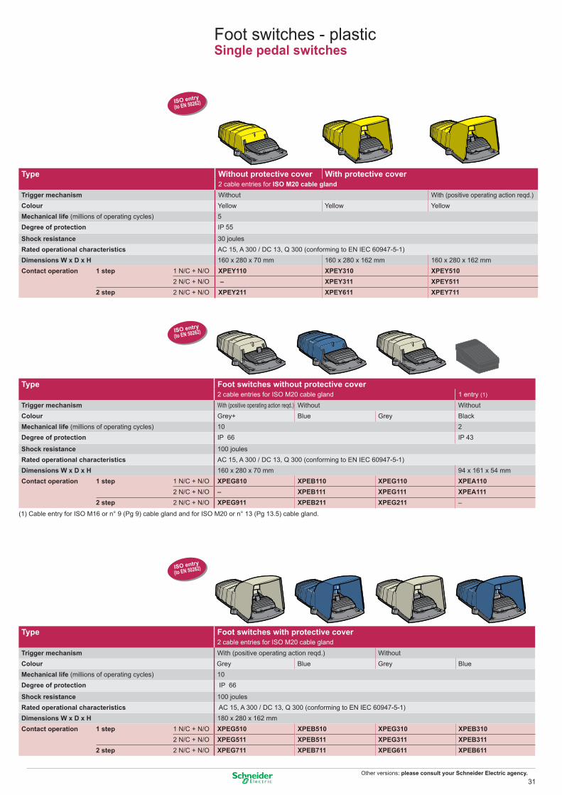
Foot switches - plasticSingle pedal switches
Type Without protective cover With protective cover2 cable entries for ISO M20 cable gland
Trigger mechanism Without With (positive operating action reqd.)Colour Yellow Yellow YellowMechanical life (millions of operating cycles) 5Degree of protection IP 55
Shock resistance 30 joulesRated operational characteristics AC 15, A 300 / DC 13, Q 300 (conforming to EN IEC 60947-5-1)Dimensions W x D x H 160 x 280 x 70 mm 160 x 280 x 162 mm 160 x 280 x 162 mmContact operation 1 step 1 N/C + N/O XPEY110 XPEY310 XPEY510
2 N/C + N/O – XPEY311 XPEY5112 step 2 N/C + N/O XPEY211 XPEY611 XPEY711
Type Foot switches without protective cover2 cable entries for ISO M20 cable gland 1 entry (1)
Trigger mechanism With (positive operating action reqd.) Without WithoutColour Grey+ Blue Grey BlackMechanical life (millions of operating cycles) 10 2Degree of protection IP 66 IP 43
Shock resistance 100 joulesRated operational characteristics AC 15, A 300 / DC 13, Q 300 (conforming to EN IEC 60947-5-1)Dimensions W x D x H 160 x 280 x 70 mm 94 x 161 x 54 mmContact operation 1 step 1 N/C + N/O XPEG810 XPEB110 XPEG110 XPEA110
2 N/C + N/O – XPEB111 XPEG111 XPEA1112 step 2 N/C + N/O XPEG911 XPEB211 XPEG211 –
(1) Cable entry for ISO M16 or n° 9 (Pg 9) cable gland and for ISO M20 or n° 13 (Pg 13.5) cable gland.
Type Foot switches with protective cover2 cable entries for ISO M20 cable gland
Trigger mechanism With (positive operating action reqd.) WithoutColour Grey Blue Grey BlueMechanical life (millions of operating cycles) 10Degree of protection IP 66
Shock resistance 100 joulesRated operational characteristics AC 15, A 300 / DC 13, Q 300 (conforming to EN IEC 60947-5-1)Dimensions W x D x H 180 x 280 x 162 mmContact operation 1 step 1 N/C + N/O XPEG510 XPEB510 XPEG310 XPEB310
2 N/C + N/O XPEG511 XPEB511 XPEG311 XPEB3112 step 2 N/C + N/O XPEG711 XPEB711 XPEG611 XPEB611
31

Other versions: please consult your Schneider Electric agency.
ISO entry(to EN 50262)
0 1 2
1-25-63-4
0 1 2
7 8 (XY2-AU2)
1-25-63-4
0 1 2
1-25-63-4
0 1 2
7 8 (XY2-AU2)
1-25-63-4
20 12
1 34 6
520 12
1 34 6
5 20 12
1 34 6
5
78
20 12
1 34 6
5
78
PreventaOperator dialog
Control unitsTwo-hand control
Type Two-hand control stations2 cable entries for ISO M20 or n° 13 (Pg 13.5) cable gland, 1 cable entry for n° 21 (Pg 21) cable gland (2)
Mechanical life (millions of operating cycles) 1 1Degree of protection IP 65 IP 65Rated operational characteristics AC 15, A 600 / DC 13, Q 600 (conforming to EN IEC 60947-5-1)Dimensions W x D x H 455 x 170 x 188.5 mmRed emergency stop (N/C + N/C slow break) XY2SB71 (1) XY2SB72 (1)Yellow lock out (N/C + N/O break before make) XY2SB75 XY2SB76
2 control pushbuttons and 1 mushroom headEmergency stop or Lock out pushbutton
(1) To order a two-hand control station with pedestal XY2SB90, add 4 to the end of the reference (example: XY2SB71 becomes XY2SB714).
2 control pushbuttons and 1 mushroom head Emergencystop or Lock out pushbutton, with pre-wired terminal block
Enabling switchContact states
(2) For entry for ISO M25 cable gland, also order adaptor DE9RA2125 + fi xing nut DE9EC21 (sold in lots of 5).
For fi xing accessories, please refer to www.schneider-electric.com.
Contact closed
Contact open
Type Plastic gripEntry for Ø 7 to 13 mm cable
Number of contacts 3 3Type of contacts 2 “NO” + 1 “NC” 2 “NO” + 1 “NC”
1 "NO" auxiliaryDescription 3 positions 3 positions with button for N/O contact (auxiliary)Shock / vibration resistance 10 gn / 6 gnDegree of protection IP 66 IP 65Rated operational characteristics AC 15, C300 / DC 13, R300 (conforming to EN IEC 60947-5-1)Dimensions W x D x H 46 x 58 x 261 mm 46 x 58 x 269 mmReferences XY2AU1 XY2AU2
32

Other versions: please consult your Schneider Electric agency.
1/L1
2/T1
3/L2
4/T2
5/L3
6/T3
1/L1
2/T1
3/L2
4/T2
5/L3
6/T3
1/L1
2/T1
3/L2
4/T2
5/L3
6/T3
1/L1
2/T1
3/L2
4/T2
5/L3
6/T3
1/L1
2/T1
3/L2
4/T2
5/L3
6/T3
1/L1
2/T1
3/L2
4/T2
5/L3
6/T3
VarioMotor control
Switch disconnectorsFront mounting
Door mounting
Door mounting
Backplate mounting in enclosure
(1) Dimensions W x D x H: 150 x 152 x 170 mm.
Enclosed
Backplate mounting in enclosure
Type Mini-Vario for standard applications
Front plate dimensions (mm) 60 x 60 60 x 60Fixing Ø 22.5 mm Ø 22.5 mmDegree of protection IP 20 IP 20Rated operational voltage (Ue) 690 V 690 VThermal current in open air (Ith) 12 A VCDN12 VCCDN12 20 A VCDN20 VCCDN20
Type Vario for high performance applications
Front plate dimensions (mm) 60 x 60 60 x 60 90 x 90 60 x 60 60 x 60 90 x 90Fixing Ø 22.5 mm 4 screws 4 screws Ø 22.5 mm 4 screws 4 screwsDegree of protection IP 20 IP 20 IP 20 IP 20 IP 20 IP 20Rated operational voltage (Ue) 690 V 690 V 690 V 690 V 690 V 690 VThermal current in open air (Ith) 12 A VCD02 VCF02 – VCCD02 VCCF02 – 20 A VCD01 VCF01 – VCCD01 VCCF01 –
25 A VCD0 VCF0 – VCCD0 VCCF0 –32 A VCD1 VCF1 – VCCD1 VCCF1 –40 A VCD2 VCF2 – VCCD2 VCCF2 –63 A – VCF3 – – VCCF3 –80 A – VCF4 – – VCCF4 –125 A – – VCF5 – – VCCF5175 A – – VCF6 – – VCCF6
Type Mini-Vario Vario
Front plate dimensions (mm) 60 x 60 60 x 60 90 x 90Dimensions W x D x H 82.5 x 106 x 131 mm 90 x 131 x 146 mm 241 x 191 x 291 mmDegree of protection IP 55 IP 65 IP 65Rated operational voltage (Ue) 690 V 690 V 690 VThermal current in enclosure (Ithe) 10 A VCFN12GE VCF02GE – 16 A VCFN20GE VCF01GE –
20 A VCFN25GE VCF0GE –25 A VCFN32GE VCF1GE –32 A VCFN40GE VCF2GE –50 A – VCF3GE (1) –63 A – VCF4GE (1) –100 A – – VCF5GEN140 A – – VCF6GEN
33
Other versions: please consult your Schneider Electric agency.
T1 T2 T3
1/L1
3/L2
5/L3
T1 T2 T3
1/L1
3/L2
5/L3
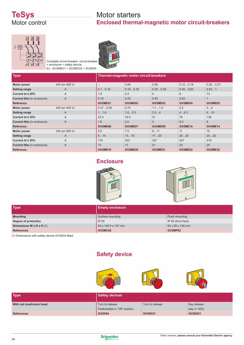
Motor startersEnclosed thermal-magnetic motor circuit-breakers
Complete circuit-breaker: circuit-breaker + enclosure + safety device.Ex.: GV2ME01 + GV2MC02 + GV2K04.
(1) Dimensions with safety device GV2K04 fi tted.
Enclosure
Safety device
TeSysMotor control
Type Thermal-magnetic motor circuit-breakers
Motor power kW (on 400 V) – 0.06 0.09 0.12…0.18 0.25…0.37Setting range A 0.1…0.16 0.16…0.25 0.25…0.40 0.40…0.63 0.63…1Current Id ± 20% A 1.5 2.4 5 8 13Current Ithe (in enclosure) A 0.16 0.25 0.40 0.63 1Reference GV2ME01 GV2ME02 GV2ME03 GV2ME04 GV2ME05Motor power kW (on 400 V) 0.37…0.55 0.75 1.1…1.5 2.2 3…4Setting range A 1…1.6 1.6…2.5 2.5…4 4…6.3 6…10Current Id ± 20% A 22.5 33.5 51 78 138Current Ithe (in enclosure) A 1.6 2.5 4 6.3 9Reference GV2ME06 GV2ME07 GV2ME08 GV2ME10 GV2ME14Motor power kW (on 400 V) 5.5 7.5 9…11 11 15Setting range A 9…14 13…18 17…23 20…25 24…32Current Id ± 20% A 170 223 327 327 416Current Ithe (in enclosure) A 13 17 21 23 24Reference GV2ME16 GV2ME20 GV2ME21 GV2ME22 GV2ME32
Type Empty enclosure
Mounting Surface mounting Flush mountingDegree of protection IP 55 IP 55 (front face)Dimensions W x D x H (1) 93 x 145.5 x 147 mm 93 x 55 x 126 mmReferences GV2MC02 GV2MP02
Type Safety devices
With red mushroom head Turn to release Turn to release Key releasePadlockable in “Off” position (key n° 455)
References GV2K04 GV2K031 GV2K021
34

Other versions: please consult your Schneider Electric agency.
With integral control transformer, 400/24 V With integral control transformer, 400/24 V
The control circuit must be cabled by the user.
Type Non reversing Reversing
Degree of protection IP 657 IP 657 IP 657Standard motor power ratings (kW), category AC3 Ith setting Basic reference, to be completed by code indicating voltage (1)
220/230 V 400/415 V 440 V range (A)– 0.06 0.06 0.16…0.25 LG1K065pp02 LG7K06pp02 LG8K06pp020.06 0.09 0.12 0.25…0.40 LG1K065pp03 LG7K06pp03 LG8K06pp03– 0.18 0.18 0.40…0.63 LG1K065pp04 LG7K06pp04 LG8K06pp040.12 0.25 0.25 0.63…1 LG1K065pp05 LG7K06pp05 LG8K06pp050.25 0.55 0.55 1…1.6 LG1K065pp06 LG7K06pp06 LG8K06pp060.37 0.75 1.1 1.6…2.5 LG1K065pp07 LG7K06pp07 LG8K06pp070.75 1.5 1.5 2.5…4 LG1K065pp08 LG7K06pp08 LG8K06pp081.1 2.2 3 4…6.3 LG1K065pp10 LG7K06pp10 LG8K06pp101.5 4 4 6…10 LG1K095pp14 LG7K09pp14 LG8K09pp143 5.5 5.5 9…14 LG1D122pp16 LG7D12pp16 LG8K12pp164 7.5 9 13…18 LG1D182pp20 LG7D18pp20 –4 9 9 17…23 LG1D182pp21 LG7D18pp21 –
Type Non reversing Reversing
Degree of protection IP 657 IP 657Standard motor power ratings (kW), category AC3 Ith setting Basic references380/400 V range (A) (The code Q7 (380/400 V) designates the power supply voltage to which the starter will be connected)
0.06 0.16…0.25 LJ7K06Q702 LJ8K06Q7020.09 0.25…0.40 LJ7K06Q703 LJ8K06Q7030.18 0.40…0.63 LJ7K06Q704 LJ8K06Q7040.25 0.63…1 LJ7K06Q705 LJ8K06Q7050.55 1…1.6 LJ7K06Q706 LJ8K06Q7060.75 1.6…2.5 LJ7K06Q707 LJ8K06Q7071.5 2.5…4 LJ7K06Q708 LJ8K06Q7082.2 4…6.3 LJ7K06Q710 LJ8K06Q7104 6…10 LJ7K09Q714 LJ8K09Q714
Control circuit voltages available
Volts 50/60 Hz 24 V 230 V 400 V 415 V(1) Voltage code B7 P7 V7 N7
35

04/2010 - V7.1ART. 805674
DIA
4ED
2041
204E
N
Head Offi ce35, rue Joseph Monier - CS 30323F92500 Rueil-Malmaison CedexFrance
www.schneider-electric.com
The information provided in this documentation contains general descriptions and/or technical characteristics of the performance of the products contained herein. This documentation is not intended as a substitute for and is not to be used for determining suitability or reliability of these products for specifi c user applications. It is the duty of any such user or integrator to perform the appropriate and complete risk analysis, evaluation and testing of the products with respect to the relevant specifi c application or use thereof. Neither Schneider Electric nor any of its affi liates or subsidiaries shall be responsible or liable for misuse of the information contained herein.
Design : IGS-CPPhotos : Schneider ElectricPrint :
Schneider Electric Industries SAS