PRESTRESSED CONCRETE PILE NOTES · SQUARE PRESTRESSED CONCRETE PILE SPLICES . 6 / 2 8 / 2 0 1 2 3:1...
14
6/ 28/ 2012 3: 14: 48 PM REVI SI ON C:\ d\ pr o j ec t s \ s t andar ds \ s t r uc t ur e s \ 2013book \ 20600- 1o f 1. dgn NO. SHEET NO. INDEX r d960r h DESCRIPTION: REVISION LAST 2013 FDOT DESIGN STANDARDS L W3.4 (All others) W4.0 (30" Piles) Spiral Ties - Cov e r 3 " Cover 3" Chamfer (Typ.) " 4 3 1" Rad. or " Max. 4 1 D " Max. 4 1 D " Max. 4 1 D " Max. 4 1 99 69 48 52 75 107 121 85 59 62 89 128 140 98 68 87 124 178 2, 3, or 4 point 2, 3, or 4 point 3 or 4 point 3 Point 2 Point 1 Point Support Points Tie Down and 0.21L 0.58L L 0.21L 0.145L 0.355L L 0.355L 0.145L Tie Down and Support Points Tie Down and Support Points 0.107L 0.262L 0.262L 0.262L 0.107L Pick-up Points 0.145L L 0.355L 0.355L 0.145L L Pick-up Points 0.21L 0.58L 0.21L L Pick-up Point 0.3L 0.7L PRESTRESSED CONCRETE PILE NOTES: 2-POINT SUPPORT 3-POINT SUPPORT 4-POINT SUPPORT STORAGE AND TRANSPORTATION SUPPORT DETAILS PILE PICK-UP DETAILS 3-POINT PICK-UP 2-POINT PICK-UP 1-POINT PICK-UP TABLE OF MAXIMUM PILE PICK-UP AND SUPPORT LENGTHS D = Square Pile Size (inches) 20 24 30 18 14 12 (Feet) Length Pile Maximum Transportation Detail Required Storage and Pick-Up Detail TYPICAL COVER DETAIL SHOWING FOR MOLD FORMS TYPICAL PILE SHAPE compound meeting the requirements of Specification Section 926. back to a minmum depth of 1 inch below the concrete surface and patch with a Type F epoxy conditions, protect the strands as follows: Prior to shipment, cut strands at appropiate end(s) For all piles having ends exposed to the environment and not embedded under final CORROSION PROTECTION OF EXPOSED STRANDS: Prestressing steel shall be seven-wire strand, Grade 270, Low-Relaxation Strand (LRS). PRESTRESSING STEEL: cold-drawn steel wire meeting the requirements of ASTM A82. All reinforcing steel shall be Grade 60, except that spiral ties shall be manufactured from REINFORCING STEEL: lines. Piles shall be marked at the pick-up points to indicate proper points for attaching handling PICK-UP POINTS: the manufacturer and in the proportions recommended. by the Manufacturer. For Epoxy Mortar only use sand or other filler material supplied by Qualified Products List (QPL). Use Epoxy Bonding Compound or Epoxy Mortar as recommended Epoxy Compound in accordance with Specification Section 926 and shall be contained on the The material to fill dowel holes and form the joint between pile sections shall be a Type B SPLICE BONDING MATERIAL: time of transfer of the Prestressing Force. Capacity Piles (Index 20631) shall be 8,500 psi minimum at 28 days and 6,500 psi minimum at time of transfer of the Prestressing Force. The cylinder strength for designated High Moment The pile cylinder strength shall be 6,000 psi minimum at 28 days and 4,000 psi minimum at CONCRETE STRENGTH: Silica Fume is required. See "GENERAL NOTES" in Structures Plans for any specific locations where the use of Concrete for the High Capacity Collar Splice shall be Class V (Special). (Index 20631) shall be Class VI. Concrete for all piles shall be Class V (Special) except designated High Moment Capacity Piles CONCRETE CLASS: spiral splices. Each wrap of spirals shall be tied to at least two corner strands. One turn required for SPIRAL TIES: Design Specifications", current edition. American Association of State Highway and Transportation Officials (AASHTO) "LRFD Bridge edition. Florida Department of Transportation (FDOT) "Structures Design Guidelines", current DESIGN SPECIFICATIONS: 01/01/12 20600 1 NOTES AND DETAILS FOR SQUARE PRESTRESSED CONCRETE PILES
Transcript of PRESTRESSED CONCRETE PILE NOTES · SQUARE PRESTRESSED CONCRETE PILE SPLICES . 6 / 2 8 / 2 0 1 2 3:1...
6/28/2012
3:1
4:4
8 P
M
RE
VISIO
N
C:\
d\projects\standards\structures\2013book\20600-1of1.d
gn
NO.
SHEET
NO.
INDEX
rd960rh
DESCRIPTION:
REVISION
LAST
2013
FDOT DESIGN STANDARDS
L
W3.4 (All others)
W4.0 (30" Piles)
Spiral Ties -
Cover
3"
Cover
3"Chamfer (Typ.)
" 431" Rad. or
" Max.41
D
" Max.41
D
" Max.41
D
" Max.41
99
69
48 52
75
107 121
85
59 62
89
128 140
98
68 87
124
178
2, 3, or 4 point
2, 3, or 4 point
3 or 4 point 3 Point
2 Point
1 Point
Support Points
Tie Down and0.21L0.58L
L
0.21L
0.145L 0.355L
L
0.355L 0.145L Tie Down and
Support Points
Tie Down and
Support Points
0.107L0.262L0.262L0.262L0.107L
Pick-up Points
0.145L
L
0.355L0.355L0.145L
L
Pick-up Points
0.21L0.58L0.21L
L
Pick-up Point
0.3L0.7L
PRESTRESSED CONCRETE PILE NOTES:
2-POINT SUPPORT
3-POINT SUPPORT
4-POINT SUPPORT
STORAGE AND TRANSPORTATION SUPPORT DETAILSPILE PICK-UP DETAILS
3-POINT PICK-UP
2-POINT PICK-UP
1-POINT PICK-UP
TABLE OF MAXIMUM PILE PICK-UP AND SUPPORT LENGTHS
D = Square Pile Size (inches)
20 24 30181412
(Feet)
Length
Pile
Maximum
Transportation Detail
Required Storage andPick-Up Detail
TYPICAL COVER
DETAIL SHOWING
FOR MOLD FORMS
TYPICAL PILE SHAPE
compound meeting the requirements of Specification Section 926.
back to a minmum depth of 1 inch below the concrete surface and patch with a Type F epoxy
conditions, protect the strands as follows: Prior to shipment, cut strands at appropiate end(s)
For all piles having ends exposed to the environment and not embedded under final
CORROSION PROTECTION OF EXPOSED STRANDS:
Prestressing steel shall be seven-wire strand, Grade 270, Low-Relaxation Strand (LRS).
PRESTRESSING STEEL:
cold-drawn steel wire meeting the requirements of ASTM A82.
All reinforcing steel shall be Grade 60, except that spiral ties shall be manufactured from
REINFORCING STEEL:
lines.
Piles shall be marked at the pick-up points to indicate proper points for attaching handling
PICK-UP POINTS:
the manufacturer and in the proportions recommended.
by the Manufacturer. For Epoxy Mortar only use sand or other filler material supplied by
Qualified Products List (QPL). Use Epoxy Bonding Compound or Epoxy Mortar as recommended
Epoxy Compound in accordance with Specification Section 926 and shall be contained on the
The material to fill dowel holes and form the joint between pile sections shall be a Type B
SPLICE BONDING MATERIAL:
time of transfer of the Prestressing Force.
Capacity Piles (Index 20631) shall be 8,500 psi minimum at 28 days and 6,500 psi minimum at
time of transfer of the Prestressing Force. The cylinder strength for designated High Moment
The pile cylinder strength shall be 6,000 psi minimum at 28 days and 4,000 psi minimum at
CONCRETE STRENGTH:
Silica Fume is required.
See "GENERAL NOTES" in Structures Plans for any specific locations where the use of
Concrete for the High Capacity Collar Splice shall be Class V (Special).
(Index 20631) shall be Class VI.
Concrete for all piles shall be Class V (Special) except designated High Moment Capacity Piles
CONCRETE CLASS:
spiral splices.
Each wrap of spirals shall be tied to at least two corner strands. One turn required for
SPIRAL TIES:
Design Specifications", current edition.
American Association of State Highway and Transportation Officials (AASHTO) "LRFD Bridge
edition.
Florida Department of Transportation (FDOT) "Structures Design Guidelines", current
DESIGN SPECIFICATIONS:
01/01/12 20600 1
NOTES AND DETAILS FOR SQUARE PRESTRESSED
CONCRETE PILES
6/28/2012
3:1
4:5
1 P
M
RE
VISIO
N
C:\
d\projects\standards\structures\2013book\20601-1of1.d
gn
NO.
SHEET
NO.
INDEX
rd960rh
DESCRIPTION:
REVISION
LAST
2013
FDOT DESIGN STANDARDS
Driv
en prestressed pile
Do
wel
Extensio
n
Plu
s 2"
joint
Full epoxy compound
dowels in place
to fill hole with
Epoxy compound
(see Splice Details)
preformed holes
" Ø Drilled or�1
"�
Dowels
No. 10
flat surface required
No chamfer,
Do
wel
extensio
n
Buil
d-up sectio
n
Splice or
epoxy compound
Form to retain
Gasket
Full epoxy compound joint
b" (fin
al thic
kness)
̆�" (a
ppli
See Section F-F.
steel cast with pile.
Auxiliary reinforcing
Do
wel
extensio
n
Driv
en prestressed pile
10’-
6"
4’-
0"
Detail A
See
Dowels
No. 10
10’-
6"
21’-
0"
Minim
um S
plice Sectio
n
Splice sectio
n
Do
wel
extensio
n
Driv
en prestressed pile
2’-
6" (T
yp.)
Detail A
See
Splice sectio
n
21’-
0"
Minim
um S
plice Sectio
n
10’-
6"
Dowels
No. 10
1" Cover
at End
4’-
0"
Minim
um, 21’-
0"
Maxim
um Pile B
uil
d-up
Build-up
Full length of
No. 10 Dowels
Pile B
uil
d-up
Driv
en prestressed pile
2’-
6" (T
yp.)
Detail A
See
Do
wel
extensio
n
BEFORE BONDING
TYPICAL SPLICE
PILE SPLICE DETAIL
PRESTRESSED PRECAST
DRIVABLE PREPLANNED
DETAIL A
E
FF
E
PILE SPLICE DETAIL
PRESTRESSED PRECAST
DRIVABLE UNFORESEEN
EEDD
PILE BUILD-UP DETAIL
REINFORCED PRECAST
NONDRIVABLE UNFORESEEN
pile (see Note No. 4)
4’-2" long, in driven
Preformed holes,
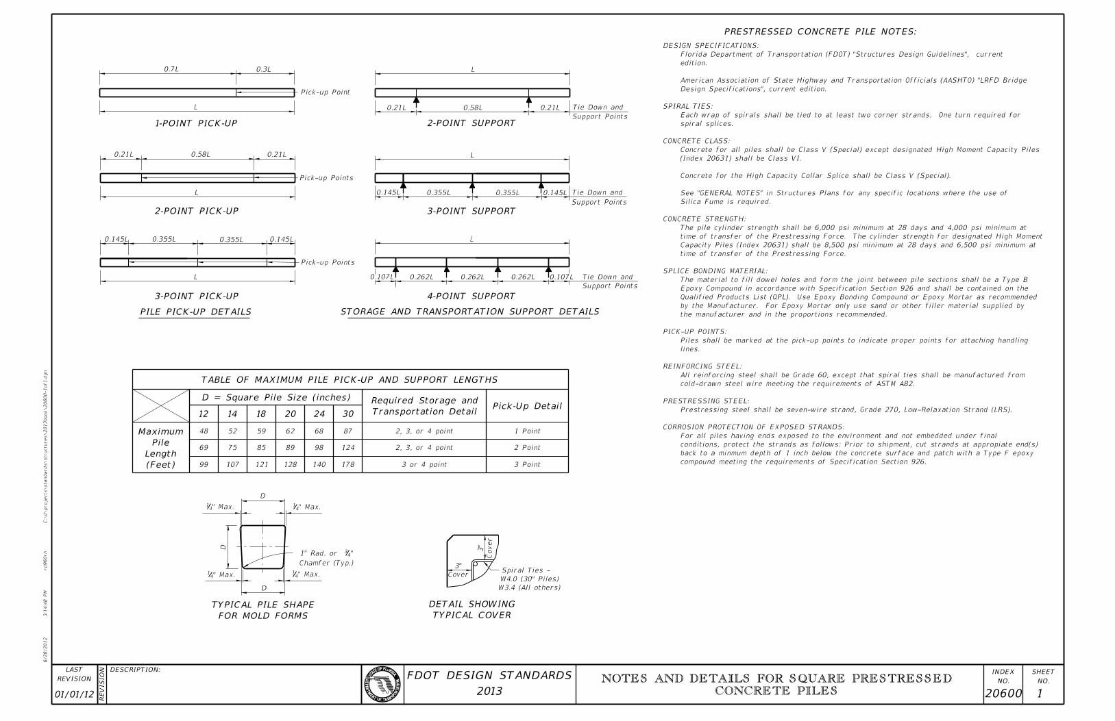
welded or interlocked seams. Galvanizing of welded seams will not be required.
shall be 2" diameter with a minimum corrugation (rib) height of 0.12 in. Ducts shall be fabricated with either
galvanized sheet steel meeting the requirements of ASTM A653, Coating Designation G90, 26 gauge. Ducts
material or stay-in-place corrugated galvanized steel ducts. Stay-in-place ducts shall be fabricated from
of the pile, See Index Nos. 20618, 20620 & 20624. Preformed holes shall utilize either removable preforming
4. When preformed dowel holes are utilized, the 1" spiral tie pitch shall be continued to 4’-0" below the head
Qualified Products List (QPL) may also be used.
Preplanned Prestressed Precast Splice Detail" shall be used. Mechanical Pile Splices contained on the
3. In cases where pile splices are desired due to length limitations in shipping and/or handling, the "Drivable
2. Prestressing strands, spiral ties and/or reinforcement are not shown for clarity.
concrete pile size and Pile Splice Reinforcement Details.
1. For Sections D-D, E-E, & F-F see Index Nos. 20612, 20614, 20618, 20620, 20624 or 20630 for applicable
NOTES:
01/01/12 20601 1
SQUARE PRESTRESSED CONCRETE PILE SPLICES
6/28/2012
3:1
4:5
3 P
M
RE
VISIO
N
C:\
d\projects\standards\structures\2013book\20602-1of1.d
gn
NO.
SHEET
NO.
INDEX
rd960rh
DESCRIPTION:
REVISION
LAST
2013
FDOT DESIGN STANDARDS
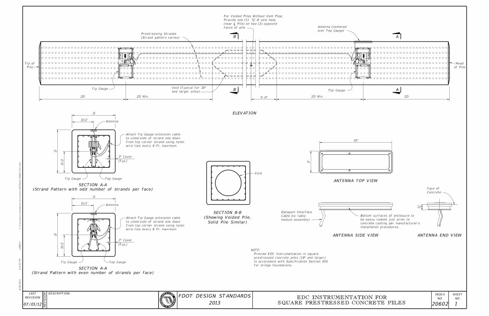
Concrete
Face of
installation procedures.
concrete casting per manufacturer’s
be epoxy coated just prior to
Bottom surfaces of enclosure to
module assembly)
Cable (to radio
Dataport Interface
3"
10"
"�
Void
Top GaugeTip Gauge
D/2
D
(Typ.)
3" Cover
AntennaD/2
D
Top Gauge
(Typ.)
3" Cover
Tip Gauge
D/2
D
Antenna
D
D/2
2D Min.
Top Gauge
2D
of Pile
Head
over Top Gauge)
Antenna (centered
(Strand pattern varies)
Prestressing Strands
and larger piles)
Void (Typical for 30" Tip Gauge
2D 2D Min.
Pile
Tip of
A
AB
B
ELEVATION
(Strand Pattern with odd number of strands per face)
SECTION A-A
(Strand Pattern with even number of strands per face)
SECTION A-A
Solid Pile Similar)
(Showing Voided Pile,
SECTION B-B
ANTENNA SIDE VIEW
ANTENNA TOP VIEW
ANTENNA END VIEW
for bridge foundations.
in accordance with Specification Section 455
prestressed concrete piles (18" and larger)
Provide EDC Instrumentation in square
NOTE:
wire ties every 6 Ft. maximum.
from top corner strand using nylon
to underside of strand one down
Attach Tip Gauge extension cable
wire ties every 6 Ft. maximum.
from top corner strand using nylon
to underside of strand one down
Attach Tip Gauge extension cable
5’-0"
faces of pile
(near � Pile) on two (2) opp
Provide one (1) ˘�" ˆ� vent
For Voided Piles Without Vent Pipe,
07/01/12 20602 1
EDC INSTRUMENTATION FOR
SQUARE PRESTRESSED CONCRETE PILES
6/28/2012
3:1
4:5
7 P
M
RE
VISIO
N
C:\
d\projects\standards\structures\2013book\20612-1of1.d
gn
NO.
SHEET
NO.
INDEX
rd960rh
DESCRIPTION:
REVISION
LAST
2013
FDOT DESIGN STANDARDS
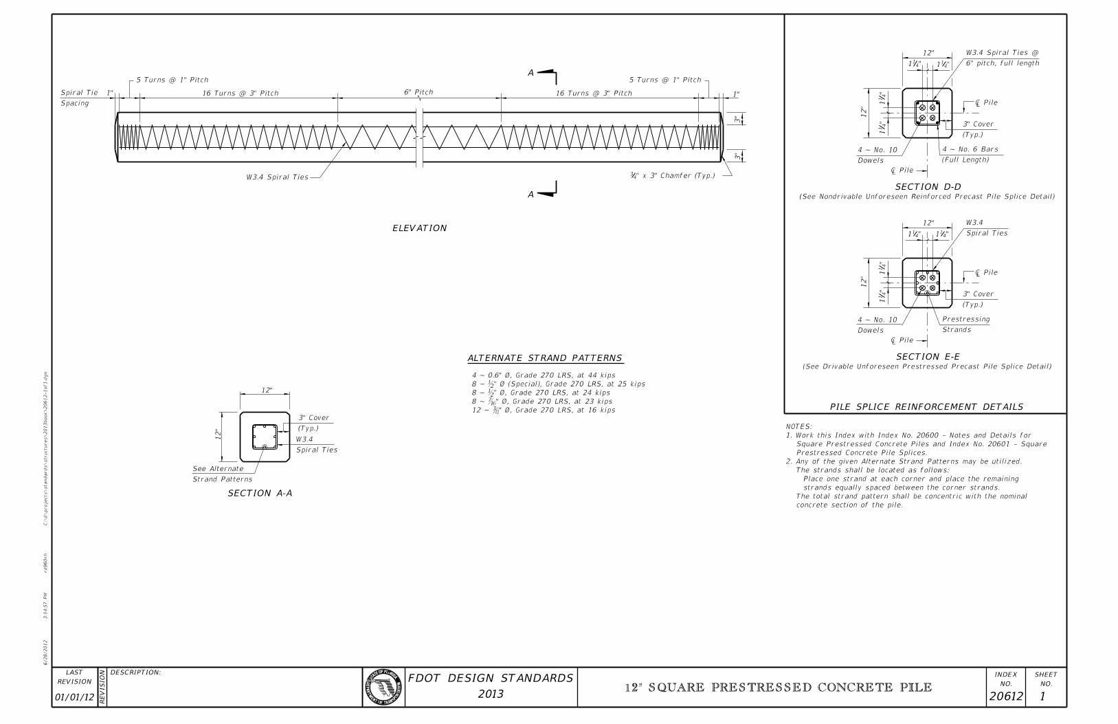
(See Drivable Unforeseen Prestressed Precast Pile Splice Detail)
Dowels
4 ~ No. 10
Strands
Prestressing
(Typ.)
3" Cover
"4
11
"4
11
12"
"411
12"
"411 Spiral Ties
W3.4
(See Nondrivable Unforeseen Reinforced Precast Pile Splice Detail)
(Full Length)
4 ~ No. 6 Bars
Dowels
4 ~ No. 10
"4
11
"4
11
12"
(Typ.)
3" Cover
"411"4
11
12"
3"
3"
1"
5 Turns @ 1" Pitch
16 Turns @ 3" Pitch 6" Pitch
W3.4 Spiral Ties
16 Turns @ 3" Pitch
5 Turns @ 1" Pitch
1"
Spacing
Spiral Tie
12"
(Typ.)
3" Cover
Spiral Ties
W3.4
Strand Patterns
See Alternate
12"
PILE SPLICE REINFORCEMENT DETAILS
SECTION E-EALTERNATE STRAND PATTERNS
SECTION D-DA
ELEVATION
A
SECTION A-A
" x 3" Chamfer (Typ.)43
�
�
�
�
concrete section of the pile.
The total strand pattern shall be concentric with the nominal
strands equally spaced between the corner strands.
Place one strand at each corner and place the remaining
The strands shall be located as follows:
2. Any of the given Alternate Strand Patterns may be utilized.
Prestressed Concrete Pile Splices.
Square Prestressed Concrete Piles and Index No. 20601 - Square
1. Work this Index with Index No. 20600 - Notes and Details for
NOTES:
12 ~ ˘�" ˆ�, Grade 270 LRS, at 16
8 ~ ˘�" ˆ�, Grade 270 LRS, at 23
8 ~ b" Ø, Grade 270 LRS, at 24 kips
8 ~ b" Ø (Special), Grade 270 LRS, at 25 kips
4 ~ 0.6" Ø, Grade 270 LRS, at 44 kips
6" pitch, full length
W3.4 Spiral Ties @
01/01/12 20612 1
12" SQUARE PRESTRESSED CONCRETE PILE
6/28/2012
3:1
5:0
0 P
M
RE
VISIO
N
C:\
d\projects\standards\structures\2013book\20614-1of1.d
gn
NO.
SHEET
NO.
INDEX
rd960rh
DESCRIPTION:
REVISION
LAST
2013
FDOT DESIGN STANDARDS
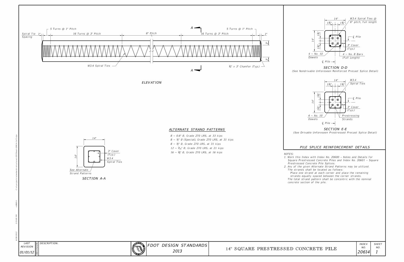
14"
"431"4
31
(Typ.)
3" Cover
(Full Length)
4 ~ No. 8 Bars
Dowels
4 ~ No. 10
"4
31
"4
31
14"
(See Nondrivable Unforeseen Reinforced Precast Splice Detail)
14"
Spiral Ties
W3.4
"431"4
31
"4
31
"4
31
14"
(Typ.)
3" Cover
Strands
Prestressing
Dowels
4 ~ No. 10
(See Drivable Unforeseen Prestressed Precast Splice Detail)
(Typ.)
3" Cover
Spiral Ties
W3.4
Strand Patterns
See Alternate
14"
14"
W3.4 Spiral Ties
16 Turns @ 3" Pitch
5 Turns @ 1" Pitch
Spacing
Spiral Tie 1" 6" Pitch 16 Turns @ 3" Pitch
5 Turns @ 1" Pitch
1"
3"
3"
A
A
ELEVATION
ALTERNATE STRAND PATTERNS
SECTION A-A
PILE SPLICE REINFORCEMENT DETAILS
SECTION E-E
SECTION D-D" x 3" Chamfer (Typ.)43
�
�
�
�
" Ø, Grade 270 LRS, at 16 kips8316 ~
" Ø, Grade 270 LRS, at 21 kips16712 ~
" Ø, Grade 270 LRS, at 31 kips218 ~
" Ø (Special), Grade 270 LRS, at 31 kips218 ~
8 ~ 0.6" Ø, Grade 270 LRS, at 33 kips
concrete section of the pile.
The total strand pattern shall be concentric with the nominal
strands equally spaced between the corner strands.
Place one strand at each corner and place the remaining
The strands shall be located as follows:
2. Any of the given Alternate Strand Patterns may be utilized.
Prestressed Concrete Pile Splices.
Square Prestressed Concrete Piles and Index No. 20601 - Square
1. Work this Index with Index No. 20600 - Notes and Details for
NOTES:
6" pitch, full length
W3.4 Spiral Ties @
01/01/12 20614 1
14" SQUARE PRESTRESSED CONCRETE PILE
6/28/2012
3:1
5:0
2 P
M
RE
VISIO
N
C:\
d\projects\standards\structures\2013book\20618-1of1.d
gn
NO.
SHEET
NO.
INDEX
rd960rh
DESCRIPTION:
REVISION
LAST
2013
FDOT DESIGN STANDARDS
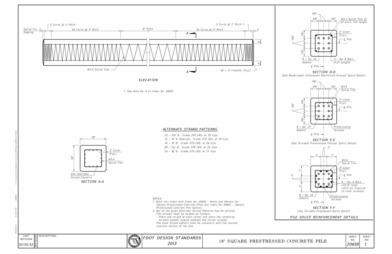
(See Drivable Preplanned Splice Detail)
Strands
PrestressingDowels
8 ~ No. 10
to clear strands)
(shift as required
(10’-6" long)
8 ~ No. 9 Bars
(Typ.)
3" Cover
Spiral Ties
W3.4
7"
2"
7"
7"
2"
7"
(See Drivable Prestressed Precast Splice Detail)
Strands
Prestressing
Dowels
8 ~ No. 10
"2
15
(Typ.)
3" Cover
Spiral Ties
W3.4
"2
15"
21
3
"215
"213
"215
(See Nondrivable Unforeseen Reinforced Precast Splice Detail)
Dowels
8 ~ No. 10
(Full Length)
4 ~ No. 8 Bars
"2
15
"2
13
"2
15 (Typ.)
3" Cover
"215
"213
"215
Spiral Ties
W3.4
Strand Patterns
See Alternate
18"
18"
(Typ.)
3" Cover
W3.4 Spiral Ties " x 3" Chamfer (Typ.)43
3"
3"
1"
5 Turns @ 1" Pitch **
16 Turns @ 3" Pitch 6" Pitch16 Turns @ 3" Pitch
5 Turns @ 1" Pitch
1"
Spacing
Spiral Tie
A
A
ELEVATION
ALTERNATE STRAND PATTERNS
SECTION A-A
PILE SPLICE REINFORCEMENT DETAILS
SECTION F-F
SECTION E-E
SECTION D-D
�
�
�
�
�
�
" Ø, Grade 270 LRS, at 17 kips8324 ~
" Ø, Grade 270 LRS, at 21 kips16720 ~
" Ø, Grade 270 LRS, at 26 kips2116 ~
" Ø (Special), Grade 270 LRS, at 34 kips2112 ~
12 ~ 0.6" Ø, Grade 270 LRS, at 35 kips
concrete section of the pile.
The total strand pattern shall be concentric with the nominal
strands equally spaced between the corner strands.
Place one strand at each corner and place the remaining
The strands shall be located as follows:
2. Any of the given Alternate Strand Patterns may be utilized.
Prestressed Concrete Pile Splices.
Square Prestressed Concrete Piles and Index No. 20601 - Square
1. Work this Index with Index No. 20600 - Notes and Details for
NOTES:
** See Note No. 4 on Index No. 20601
6" pitch, full length
W3.4 Spiral Ties @
01/01/12 20618 1
18" SQUARE PRESTRESSED CONCRETE PILE

6/28/2012
3:1
5:0
5 P
M
RE
VISIO
N
C:\
d\projects\standards\structures\2013book\20620-1of1.d
gn
NO.
SHEET
NO.
INDEX
rd960rh
DESCRIPTION:
REVISION
LAST
2013
FDOT DESIGN STANDARDS
7�
"
"215 "2
14 "214 "2
15
(Typ.)
3" Cover
"2
15
"2
14
"2
14
"2
15
Dowels
8 ~ No. 10
(Full length)
4 ~ No. 8 Bars
(See Nondrivable Unforeseen Reinforced Precast Pile Splice Detail)
"215 "2
14 "214 "2
15
Spiral Ties
W3.4
(Typ.)
3" Cover
"2
15
"2
14
"2
14
"2
15
Dowels
8 ~ No. 10
Strands
Prestressing
(See Drivable Prestressed Precast Pile Splice Detail)
"817
"872
"817
Spiral Ties
W3.4
(Typ.)
3" Cover
"8
17
"8
72
Dowels
8 ~ No. 10
Strands
Prestressing
to clear strands)
(shift as required
(10’-6" long)
8 ~ No. 10 Bars
(See Drivable Preplanned Pile Splice Detail)
(Typ.)
3" Cover
Spiral Ties
W3.4
Strand Patterns
See Alternate
20"
20"
** See Note No. 4 on Index No. 20601
" x 3" Chamfer (Typ.)43
3"
W3.4 Spiral Ties
Spacing
Spiral Tie 1"
5 Turns @ 1" Pitch
16 Turns @ 3" Pitch 6" Pitch 16 Turns @ 3" Pitch
5 Turns @ 1" Pitch **
1"
3"
SECTION D-D
SECTION E-E
SECTION F-F
PILE SPLICE REINFORCEMENT DETAILS
SECTION A-A
ALTERNATE STRAND PATTERNS
A
A
ELEVATION
�
�
�
�
�
�
24 ~ ˘�" ˆ�, Grade 270 LRS, at 21
16 ~ b" Ø, Grade 270 LRS, at 31 kips
16 ~ b" Ø (Special), Grade 270 LRS, at 31 kips
12 ~ 0.6" Ø, Grade 270 LRS, at 42 kips
concrete section of the pile.
The total strand pattern shall be concentric with the nominal
strands equally spaced between the corner strands.
Place one strand at each corner and place the remaining
The strands shall be located as follows:
2. Any of the given Alternate Strand Patterns may be utilized.
Prestressed Concrete Pile Splices.
Square Prestressed Concrete Piles and Index No. 20601 - Square
1. Work this Index with Index No. 20600 - Notes and Details for
NOTES:
6" pitch, full length
W3.4 Spiral Ties @
01/01/12 20620 1
20" SQUARE PRESTRESSED CONCRETE PILE
6/28/2012
3:1
5:0
8 P
M
RE
VISIO
N
C:\
d\projects\standards\structures\2013book\20624-1of1.d
gn
NO.
SHEET
NO.
INDEX
rd960rh
DESCRIPTION:
REVISION
LAST
2013
FDOT DESIGN STANDARDS
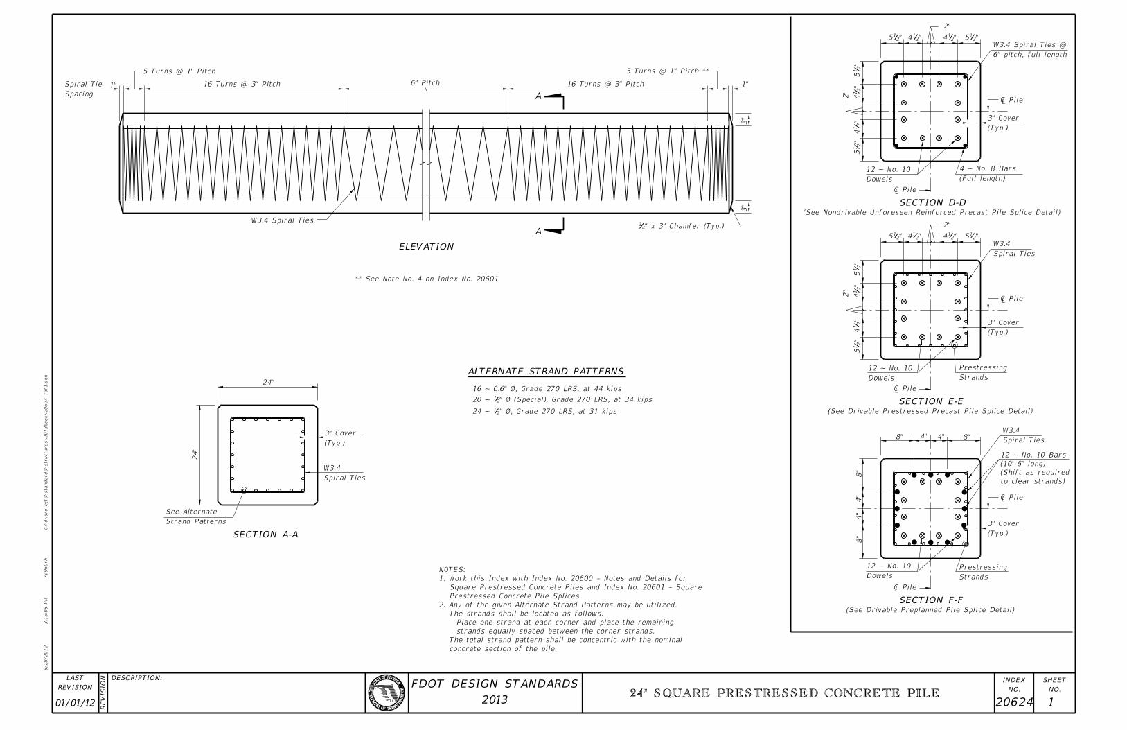
(See Drivable Preplanned Pile Splice Detail)
Dowels
12 ~ No. 10
Strands
Prestressing
(Typ.)
3" Cover
8"
4"
4"
8"
to clear strands)
(Shift as required
(10’-6" long)
12 ~ No. 10 Bars
Spiral Ties
W3.4 8"4"4"8"
(See Drivable Prestressed Precast Pile Splice Detail)
Strands
Prestressing
Dowels
12 ~ No. 10
"2
15
"2
14
2"
"2
14
"2
15
(Typ.)
3" Cover
Spiral Ties
W3.4
"215"2
14
2"
"214"2
15
(See Nondrivable Unforeseen Reinforced Precast Pile Splice Detail)
Dowels
12 ~ No. 10
(Full length)
4 ~ No. 8 Bars
(Typ.)
3" Cover
"215"2
14
2"
"214"2
15
"2
15
"2
142"
"2
14
"2
15
Strand Patterns
See Alternate
24"
Spiral Ties
W3.4
(Typ.)
3" Cover
24"
** See Note No. 4 on Index No. 20601
W3.4 Spiral Ties" x 3" Chamfer (Typ.)4
3
3"
3"
1"
5 Turns @ 1" Pitch **
16 Turns @ 3" Pitch 6" Pitch16 Turns @ 3" Pitch
5 Turns @ 1" Pitch
1"
Spacing
Spiral Tie
SECTION D-D
SECTION E-E
SECTION F-F
SECTION A-A
ALTERNATE STRAND PATTERNS
ELEVATION
A
A
�
�
�
�
�
�
" Ø, Grade 270 LRS, at 31 kips2124 ~
" Ø (Special), Grade 270 LRS, at 34 kips2120 ~
16 ~ 0.6" Ø, Grade 270 LRS, at 44 kips
concrete section of the pile.
The total strand pattern shall be concentric with the nominal
strands equally spaced between the corner strands.
Place one strand at each corner and place the remaining
The strands shall be located as follows:
2. Any of the given Alternate Strand Patterns may be utilized.
Prestressed Concrete Pile Splices.
Square Prestressed Concrete Piles and Index No. 20601 - Square
1. Work this Index with Index No. 20600 - Notes and Details for
NOTES:
6" pitch, full length
W3.4 Spiral Ties @
01/01/12 20624 1
24" SQUARE PRESTRESSED CONCRETE PILE
6/28/2012
3:1
5:1
0 P
M
RE
VISIO
N
C:\
d\projects\standards\structures\2013book\20630-1of1.d
gn
NO.
SHEET
NO.
INDEX
rd960rh
DESCRIPTION:
REVISION
LAST
2013
FDOT DESIGN STANDARDS
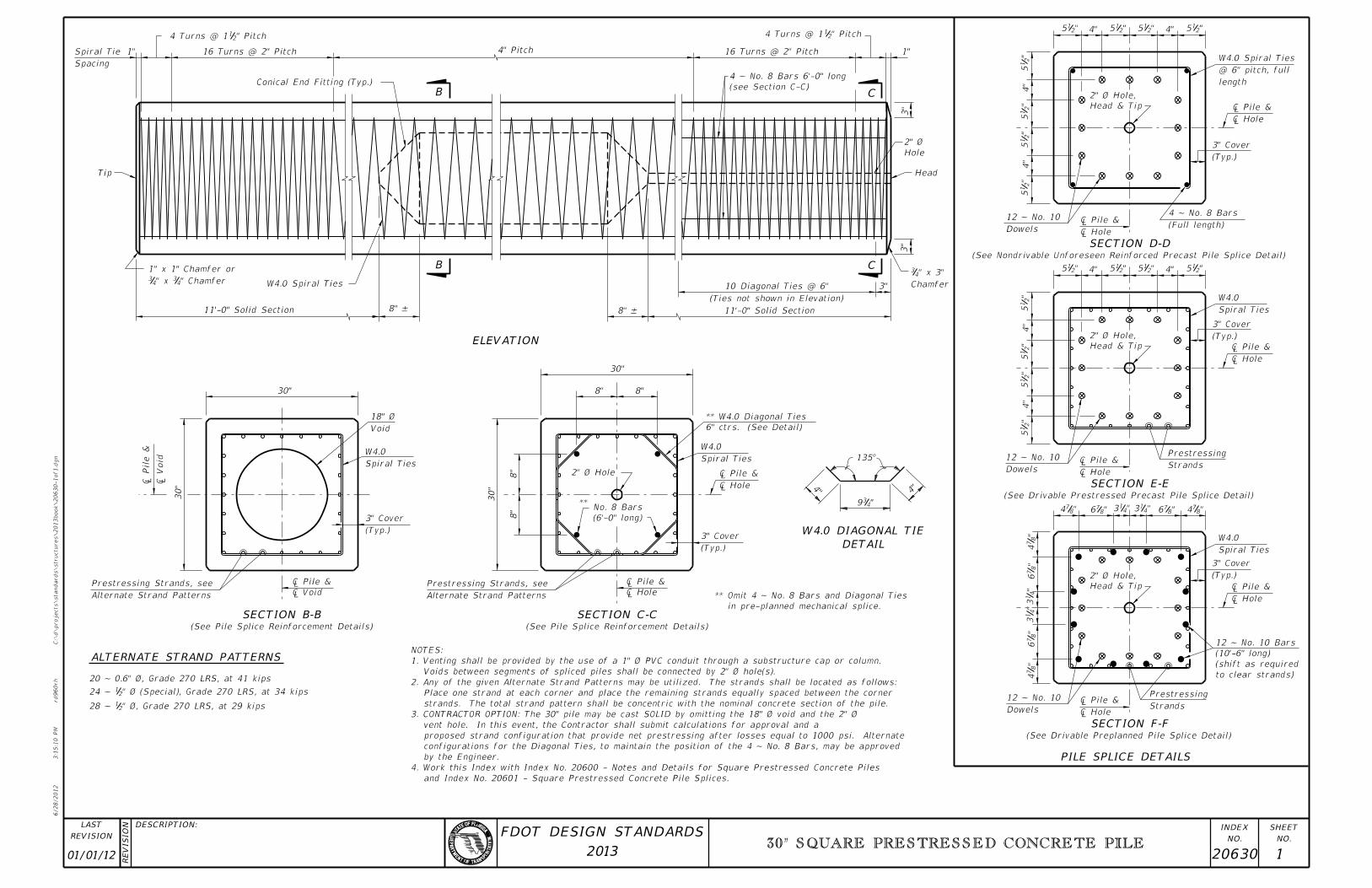
(See Drivable Preplanned Pile Splice Detail)
Dowels
12 ~ No. 10Strands
Prestressing
to clear strands)
(shift as required
(10’-6" long)
12 ~ No. 10 Bars
(Typ.)
3" Cover
Spiral Ties
W4.0
Head & Tip
2" Ø Hole,
"8
74
"8
76
"4
13
"4
13
"8
76
"8
74
"874 "8
76 "413 "4
13 "876 "8
74
(See Drivable Prestressed Precast Pile Splice Detail)
Strands
Prestressing
Dowels
12 ~ No. 10
"2
15
4"
"2
15
"2
15
4"
"2
15
Head & Tip
2" Ø Hole, (Typ.)
3" Cover
Spiral Ties
W4.0
"2154""2
15"2154""2
15
(See Nondrivable Unforeseen Reinforced Precast Pile Splice Detail)
(Full length)
4 ~ No. 8 Bars
Dowels
12 ~ No. 10
"2
15
4"
"2
15
"2
15
Head & Tip
2" Ø Hole,
(Typ.)
3" Cover
4"
"2
15
"215 4" "2
15 "215 4" "2
15
(See Pile Splice Reinforcement Details)
Alternate Strand Patterns
Prestressing Strands, see
(Typ.)
3" Cover
Alternate Strand Patterns
Prestressing Strands, see
(See Pile Splice Reinforcement Details)
in pre-planned mechanical splice.
** Omit 4 ~ No. 8 Bars and Diagonal Ties
(Typ.)
3" Cover
"439
4"
135°
4"
Spiral Ties
W4.0
6" ctrs. (See Detail)
** W4.0 Diagonal Ties
(6’-0" long)
No. 8 Bars**
8"
8"
30"
Spiral Ties
W4.0
30"
30"
8" 8"
30"
8" –8" –
W4.0 Spiral Ties" Chamfer43" x 4
3
1" x 1" Chamfer or
11’-0" Solid Section
(Ties not shown in Elevation)
10 Diagonal Ties @ 6"
11’-0" Solid Section
3" Chamfer
" x 3"43
3"
Head
3"
1"
" Pitch214 Turns @ 1
16 Turns @ 2" Pitch
(see Section C-C)
4 ~ No. 8 Bars 6’-0" long
4" Pitch
Conical End Fitting (Typ.)
16 Turns @ 2" Pitch
" Pitch214 Turns @ 1
1"
Spacing
Spiral Tie
Tip
ALTERNATE STRAND PATTERNS
SECTION B-B SECTION C-C
DETAIL
W4.0 DIAGONAL TIE
PILE SPLICE DETAILS
SECTION F-F
SECTION E-E
SECTION D-D
C
CB
B
ELEVATION
�
� P
�
� P
�
� P
�
� P
�
� P
�
� P
Hole
2" Ø
�
â�� P2" Ø Hole
�
� P
Void
18" Ø
�
� P

�

� P
" Ø, Grade 270 LRS, at 29 kips2128 ~
" Ø (Special), Grade 270 LRS, at 34 kips2124 ~
20 ~ 0.6" Ø, Grade 270 LRS, at 41 kips
and Index No. 20601 - Square Prestressed Concrete Pile Splices.
Square Prestressed Concrete Piles4. Work this Index with Index No. 20600 - Notes and Details for
by the Engineer.
configurations for the Diagonal Ties, to maintain the position of the 4 ~ No. 8 Bars, may be approved
proposed strand configuration that provide net prestressing after losses equal to 1000 psi. Alternate
vent hole. In this event, the Contractor shall submit calculations for approval and a
3. CONTRACTOR OPTION: The 30" pile may be cast SOLID by omitting the 18" Ø void and the 2" Ø
strands. The total strand pattern shall be concentric with the nominal concrete section of the pile.
Place one strand at each corner and place the remaining strands equally spaced between the corner
2. Any of the given Alternate Strand Patterns may be utilized. The strands shall be located as follows:
Voids between segments of spliced piles shall be connected by 2" Ø hole(s).
1. Venting shall be provided by the use of a 1" Ø PVC conduit through a substructure cap or column.
NOTES:
length
@ 6" pitch, full
W4.0 Spiral Ties
01/01/12 20630 1
30" SQUARE PRESTRESSED CONCRETE PILE
6/28/2012
3:1
5:1
2 P
M
RE
VISIO
N
C:\
d\projects\standards\structures\2013book\20631-1of1.d
gn
NO.
SHEET
NO.
INDEX
rd960rh
DESCRIPTION:
REVISION
LAST
2013
FDOT DESIGN STANDARDS
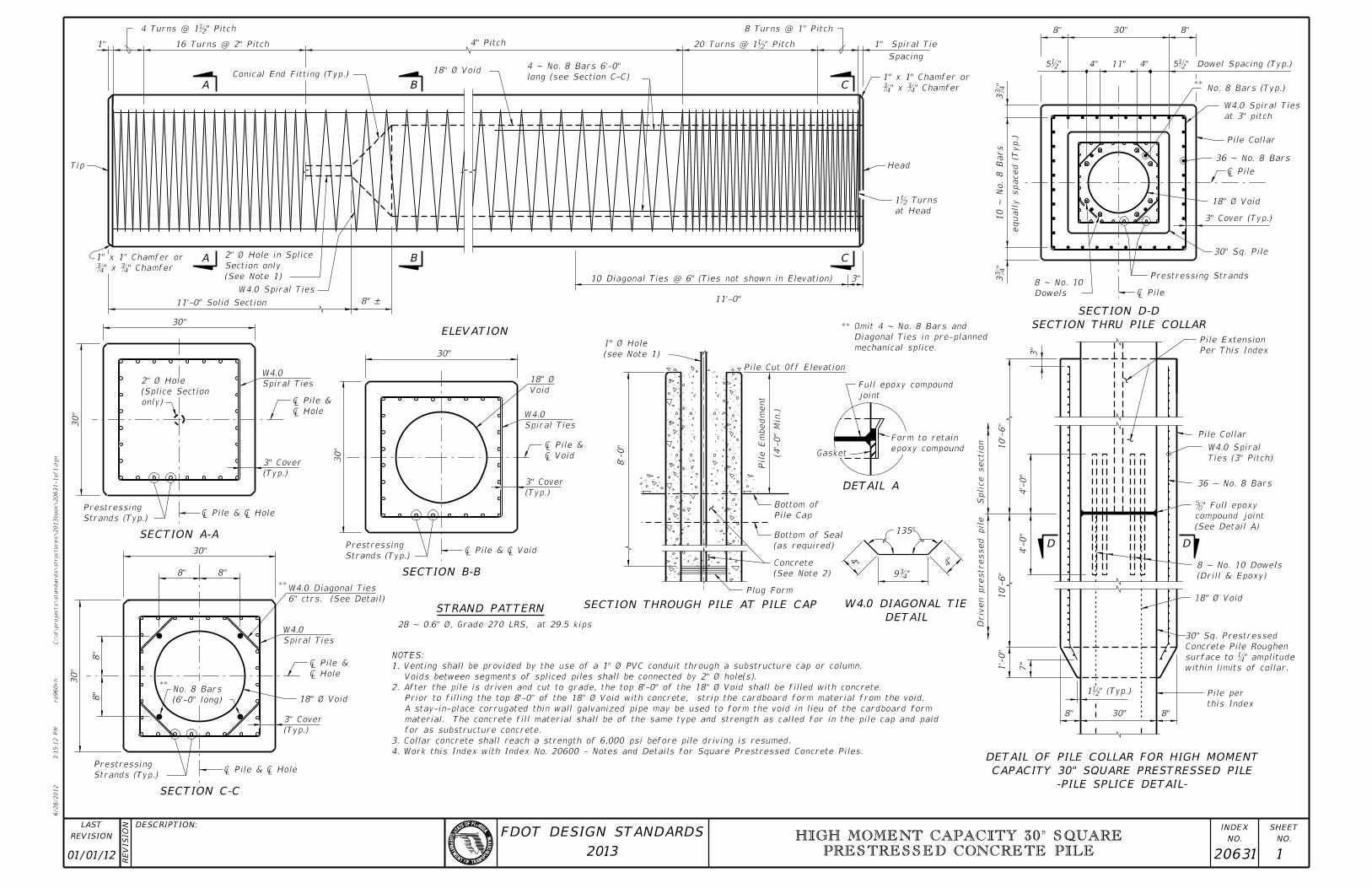
30"8"
7"
1’-
0"
this Index
Pile per
(Drill & Epoxy)
8 ~ No. 10 Dowels
10’-
6"
Driv
en prestressed pile
4’-
0"
4’-
0"
Splice sectio
n
36 ~ No. 8 Bars
Ties (3" Pitch)
W4.0 Spiral
Pile Collar
10’-
6"
3" Per This Index
Pile Extension
(See Detail A)
compound joint
" Full epoxy �
18" Ø Void
within limits of collar.
" amplitude�surface to
Concrete Pile Roughen
30" Sq. Prestressed
" (Typ.)b1
8"
4"4
"
135°
Gasket
joint
Full epoxy compound
epoxy compound
Form to retain
mechanical splice.
Diagonal Ties in pre-planned
** Omit 4 ~ No. 8 Bars and
Plug Form
(See Note 2)
Concrete
(as required)
Bottom of Seal
Pile Cap
Bottom of
(4’-
0"
Min.)
Pile E
mbed
ment
Pile Cut Off Elevation
(see Note 1)
1" Ø Hole
8’-
0"
"�9
Strands (Typ.)
Prestressing
30"
Spiral Ties
W4.0
(Typ.)
3" Cover
Void
18" Ø
�
� P
â�� Pile & â
30"
28 ~ 0.6" Ø, Grade 270 LRS, at 29.5 kips
Strands (Typ.)
Prestressing
(6’-0" long)
No. 8 Bars**
(Typ.)
3" Cover
Spiral Ties
W4.0
6" ctrs. (See Detail)
W4.0 Diagonal Ties **
8"
30"
8"
8"
8"
30"
â�� Pile & â
18" Ø Void
�
� P
Strands (Typ.)
Prestressing
(Typ.)
3" Cover
Spiral Ties
W4.0
30"
only)
(Splice Section
2" Ø Hole
30"
â�� Pile & â
�
� P
Tip
11’-0" Solid Section 8" –
W4.0 Spiral Ties
(See Note 1)
Section only
2" Ø Hole in Splice
10 Diagonal Ties @ 6" (Ties not shown in Elevation)
11’-0"
3"
at Head
Head
Spacing
1" Spiral Tie
8 Turns @ 1" Pitch
long (see Section C-C)
4 ~ No. 8 Bars 6’-0"
4" Pitch
Conical End Fitting (Typ.)
16 Turns @ 2" Pitch 1"
" Pitchb4 Turns @ 1
" Chamfer�" x �
1" x 1" Chamfer or
" Chamfer�" x �
1" x 1" Chamfer or
" Pitch b20 Turns @ 1
18" Ø Void
8"30"8"
4" 11" 4"
**No. 8 Bars (Typ.)
at 3" pitch
W4.0 Spiral Ties
Pile Collar
36 ~ No. 8 Bars
3" Cover (Typ.)
30" Sq. Pile
Prestressing Strands
Dowels
8 ~ No. 10
equall
y spaced (T
yp.)
10 ~
No.
8 Bars
"�
3
"b5 " Dowel Spacing (Typ.)b5
�
18" Ø Void
�
"�
3
DETAIL
W4.0 DIAGONAL TIE
D D
SECTION THRU PILE COLLAR
SECTION D-D
C
C
BA
A B
ELEVATION
SECTION A-A
SECTION B-B
STRAND PATTERN
SECTION C-C
SECTION THROUGH PILE AT PILE CAP
DETAIL A
-PILE SPLICE DETAIL-
CAPACITY 30" SQUARE PRESTRESSED PILE
DETAIL OF PILE COLLAR FOR HIGH MOMENT
1b Turns
4. Work this Index with Index No. 20600 - Notes and Details for Square Prestressed Concrete Piles.
3. Collar concrete shall reach a strength of 6,000 psi before pile driving is resumed.
for as substructure concrete.
material. The concrete fill material shall be of the same type and strength as called for in the pile cap and paid
A stay-in-place corrugated thin wall galvanized pipe may be used to form the void in lieu of the cardboard form
Prior to filling the top 8’-0" of the 18" Ø Void with concrete, strip the cardboard form material from the void.
2. After the pile is driven and cut to grade, the top 8’-0" of the 18" Ø Void shall be filled with concrete.
Voids between segments of spliced piles shall be connected by 2" Ø hole(s).
1. Venting shall be provided by the use of a 1" Ø PVC conduit through a substructure cap or column.
NOTES:
01/01/12 20631 1
HIGH MOMENT CAPACITY 30" SQUARE
PRESTRESSED CONCRETE PILE
6/28/2012
3:1
5:2
2 P
M
RE
VISIO
N
C:\
d\projects\standards\structures\2013book\20654-1of2.d
gn
NO.
SHEET
NO.
INDEX
rd960rh
DESCRIPTION:
REVISION
LAST
2013
FDOT DESIGN STANDARDS
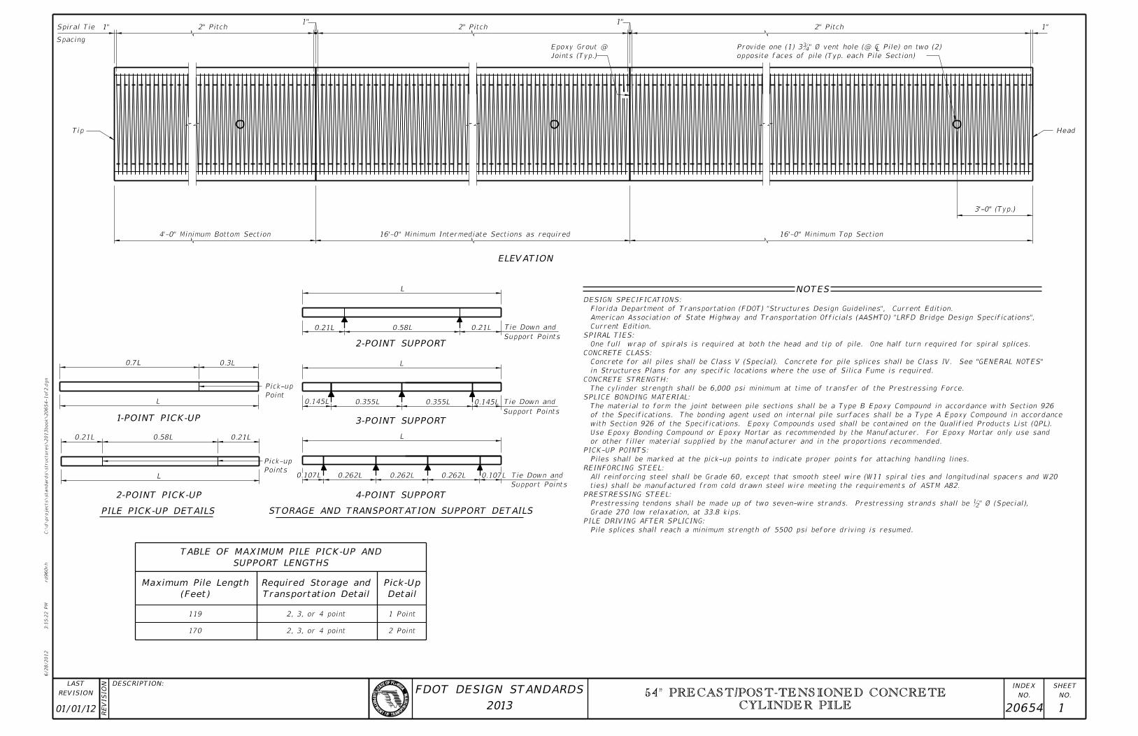
2 Point
1 Point2, 3, or 4 point
2, 3, or 4 point170
119
Support Points
Tie Down and0.107L0.262L0.262L0.262L0.107LPoints
Pick-up
0.145L 0.355L 0.355L 0.145L Tie Down and
Support Points
Support Points
Tie Down and0.21L0.58L0.21L
L
L
L
0.3L0.7L
Point
Pick-up
L
0.21L 0.58L 0.21L
L
4’-0" Minimum Bottom Section 16’-0" Minimum Intermediate Sections as required 16’-0" Minimum Top Section
3’-0" (Typ.)
Head
1"2" Pitch 1"
Joints (Typ.)
Epoxy Grout @
2" Pitch1"
2" Pitch Spiral Tie
Spacing
1"
Tip
opposite faces of pile (Typ. each Pile Section)
" ˆ� vent hole (@ â�� Pile) on tw�Provide one (1) 3
Detail
Pick-Up
Transportation Detail
Required Storage and
(Feet)
Maximum Pile Length
SUPPORT LENGTHS
TABLE OF MAXIMUM PILE PICK-UP AND
STORAGE AND TRANSPORTATION SUPPORT DETAILS
4-POINT SUPPORT2-POINT PICK-UP
PILE PICK-UP DETAILS
1-POINT PICK-UP 3-POINT SUPPORT
2-POINT SUPPORT
ELEVATION
NOTES
Pile splices shall reach a minimum strength of 5500 psi before driving is resumed.
PILE DRIVING AFTER SPLICING:
Grade 270 low relaxation, at 33.8 kips.
Prestressing tendons shall be made up of two seven-wire strands. Prestressing strands shall be b" Ø (Special),
PRESTRESSING STEEL:
ties) shall be manufactured from cold drawn steel wire meeting the requirements of ASTM A82.
All reinforcing steel shall be Grade 60, except that smooth steel wire (W11 spiral ties and longitudinal spacers and W20
REINFORCING STEEL:
Piles shall be marked at the pick-up points to indicate proper points for attaching handling lines.
PICK-UP POINTS:
or other filler material supplied by the manufacturer and in the proportions recommended.
Use Epoxy Bonding Compound or Epoxy Mortar as recommended by the Manufacturer. For Epoxy Mortar only use sand
with Section 926 of the Specifications. Epoxy Compounds used shall be contained on the Qualified Products List (QPL).
of the Specifications. The bonding agent used on internal pile surfaces shall be a Type A Epoxy Compound in accordance
The material to form the joint between pile sections shall be a Type B Epoxy Compound in accordance with Section 926
SPLICE BONDING MATERIAL:
The cylinder strength shall be 6,000 psi minimum at time of transfer of the Prestressing Force.
CONCRETE STRENGTH:
in Structures Plans for any specific locations where the use of Silica Fume is required.
Concrete for all piles shall be Class V (Special). Concrete for pile splices shall be Class IV. See "GENERAL NOTES"
CONCRETE CLASS:
One full wrap of spirals is required at both the head and tip of pile. One half turn required for spiral splices.
SPIRAL TIES:
Current Edition.
American Association of State Highway and Transportation Officials (AASHTO) "LRFD Bridge Design Specifications",
Florida Department of Transportation (FDOT) "Structures Design Guidelines", Current Edition.
DESIGN SPECIFICATIONS:
01/01/12 20654 1
54" PRECAST/POST-TENSIONED CONCRETE
CYLINDER PILE
6/28/2012
3:1
5:2
4 P
M
RE
VISIO
N
C:\
d\projects\standards\structures\2013book\20654-2of2.d
gn
NO.
SHEET
NO.
INDEX
rd960rh
DESCRIPTION:
REVISION
LAST
2013
FDOT DESIGN STANDARDS
Outside Pile Wall
epoxy compound
Form to retain
Inside Pile Wall
epoxy compound
Form to retain
Temporary Blocking
Gasket
Cover (Typ.)
3" Min.
W20 Wire Ties
No. 4 Bars or
Lap Splice
1’-0" Min.
W11 Wire Spiral Ties
Spiral Ties @ Equal Spaces
(No. 3 Bars or W11 wire) for
4 ~ Longitudinal Spacer Bars
@ Equal Spaces
24 ~ No. 11 Bars
Place Plug
Cast in
Cover (Typ.)Cover (Typ.)
3" Min.
Wire Ties
W11 Spiral
Spiral Ties @ Equal Spaces
(No. 3 Bars or W11 wire) for
4 ~ Longitudinal Spacers
for Tendons @ Equal Spaces
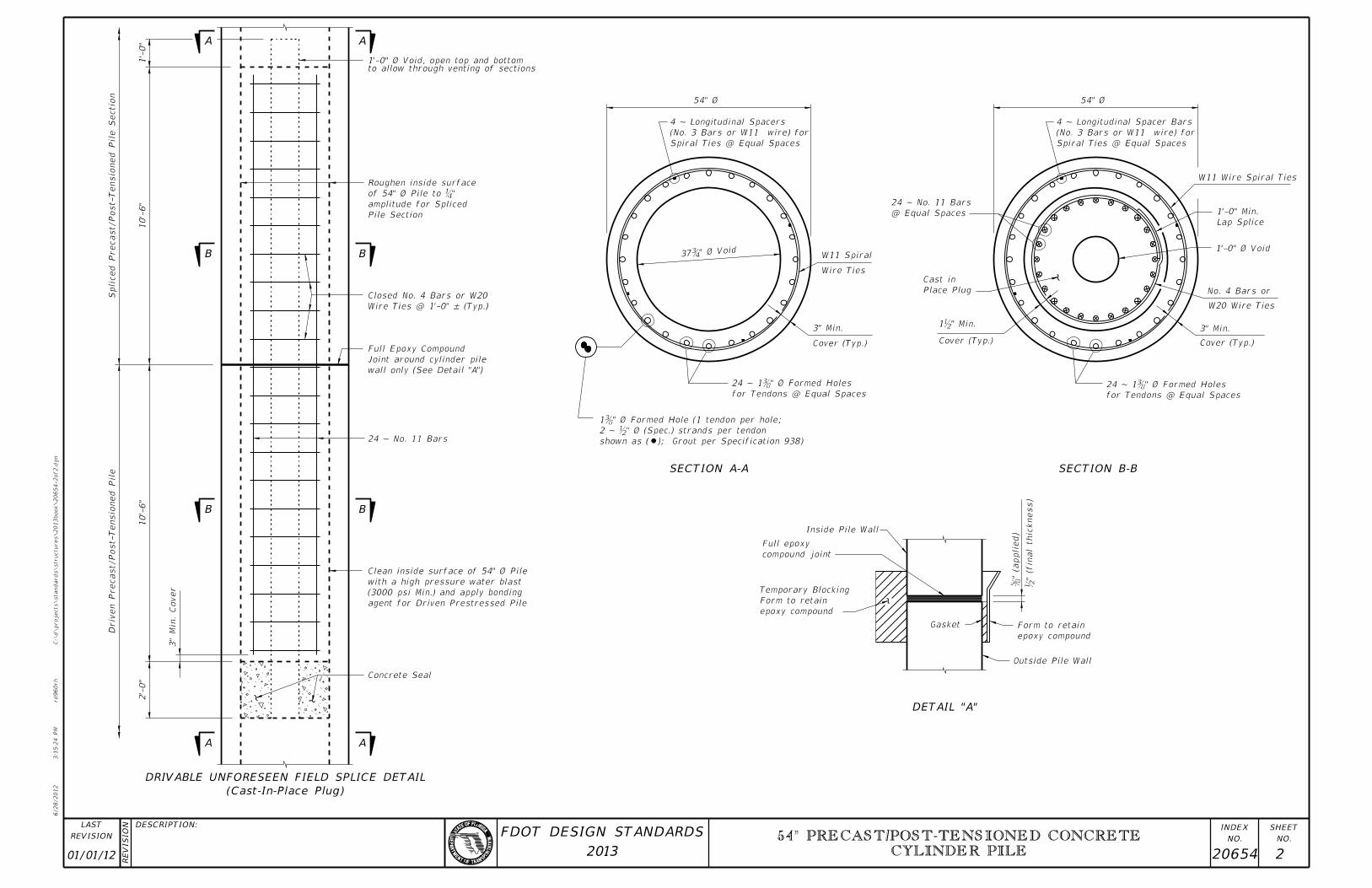
" Ø Formed Holes �24 ~ 1
1’-0" Ø Void
54" Ø
" Min.b1
54" Ø
" Ø Void�37
for Tendons @ Equal Spaces
" Ø Formed Holes �24 ~ 1
to allow through venting of sections1’-0" Ø Void, open top and bottom
Wire Ties @ 1’-0" – (Typ.)
Closed No. 4 Bars or W20
24 ~ No. 11 Bars
Concrete Seal
2’-
0"
3"
Min.
Cover
Driv
en Precast/Post-Tensio
ned Pile
10’-
6"
Spliced Precast/Post-Tensio
ned Pile Sectio
n
10’-
6"
1’-
0"
Pile Section
amplitude for Spliced
" �of 54" Ø Pile to
Roughen inside surface
agent for Driven Prestressed Pile
(3000 psi Min.) and apply bonding
with a high pressure water blast
Clean inside surface of 54" Ø Pile
SECTION B-BSECTION A-A
DETAIL "A"
AA
B B
BB
A A
wall only (See Detail "A")
Joint around cylinder pile
Full Epoxy Compound
̆�" (a
ppl
b" (fin
al thic
kness)
compound joint
Full epoxy
shown as ( ); Grout per Specification 938)
2 ~ b" Ø (Spec.) strands per tendon
1˘�" ˆ� Formed Hole (1 tendon per h
(Cast-In-Place Plug)
DRIVABLE UNFORESEEN FIELD SPLICE DETAIL
01/01/12 20654 2
54" PRECAST/POST-TENSIONED CONCRETE
CYLINDER PILE
6/28/2012
3:1
5:2
6 P
M
RE
VISIO
N
C:\
d\projects\standards\structures\2013book\20660-1of2.d
gn
NO.
SHEET
NO.
INDEX
rd960rh
DESCRIPTION:
REVISION
LAST
2013
FDOT DESIGN STANDARDS
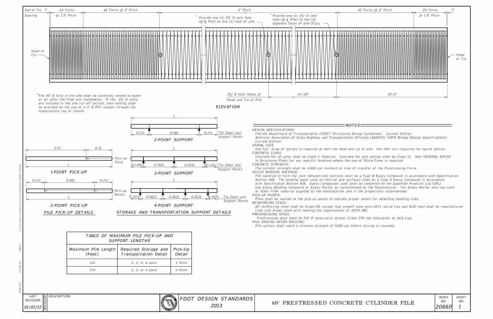
2 Point
1 Point2, 3, or 4 point
2, 3, or 4 point174
122
L
0.21L 0.58L 0.21L
Points
Pick-up
Point
Pick-up
0.3L0.7L
0.107L 0.262L 0.262L 0.262L 0.107L Tie Down and
Support Points
Support Points
Tie Down and0.145L0.355L0.355L0.145L
0.21L 0.58L 0.21L Tie Down and
Support Points
Head and Tip of Pile
14’-10" 10’-2"
or Tip
Head
1"24 Turns
@ 1.5" Pitch
42 Turns @ 2" Pitch
*
4" Pitch
*
42 Turns @ 2" Pitch 24 Turns
@ 1.5" Pitch
Spiral Tie
Spacing
1"
Tip
Head or
*
substructure cap or column.
be provided by the use of a 1" Ø PVC conduit through the
are included in the pile cut-off section, then venting shall
" Ø vents bor air after the final pile installation. If the 3
The 45" Ø Void in the pile shall be positively vented to water " Ø Vent Holes atb3
opposite faces of pile (Typ.)
hole (@ � Pile) on two
" Ø vent bProvide one (1) 3
(@ � Pile) on one (1) face of
" Ø vent holebProvide one (1) 3
Detail
Pick-Up
Transportation Detail
Required Storage and
(Feet)
Maximum Pile Length
SUPPORT LENGTHS
TABLE OF MAXIMUM PILE PICK-UP AND
4-POINT SUPPORT
STORAGE AND TRANSPORTATION SUPPORT DETAILSPILE PICK-UP DETAILS
2-POINT PICK-UP
1-POINT PICK-UP 3-POINT SUPPORT
2-POINT SUPPORT
ELEVATION
NOTES
L
L
L
L
Pile splices shall reach a minimum strength of 5500 psi before driving is resumed.
PILE DRIVING AFTER SPLICING:
Prestressing steel shall be 0.6" Ø seven-wire strand, Grade 270 low relaxation, at 44.0 kips.
PRESTRESSING STEEL:
from cold drawn steel wire meeting the requirements of ASTM A82.
All reinforcing steel shall be Grade 60, except that smooth steel wire (W11 spiral ties and W20 ties) shall be manufactured
REINFORCING STEEL:
Piles shall be marked at the pick-up points to indicate proper points for attaching handling lines.
PICK-UP POINTS:
or other filler material supplied by the manufacturer and in the proportions recommended.
Use Epoxy Bonding Compound or Epoxy Mortar as recommended by the Manufacturer. For Epoxy Mortar only use sand
with Specification Section 926. Epoxy Compounds used shall be contained on the Qualified Products List (QPL).
Section 926. The bonding agent used on internal pile surfaces shall be a Type A Epoxy Compound in accordance
The material to form the joint between pile sections shall be a Type B Epoxy Compound in accordance with Specification
SPLICE BONDING MATERIAL:
The cylinder strength shall be 4,000 psi minimum at time of transfer of the Prestressing Force.
CONCRETE STRENGTH:
in Structures Plans for any specific locations where the use of Silica Fume is required.
Concrete for all piles shall be Class V (Special). Concrete for pile splices shall be Class IV. See "GENERAL NOTES"
CONCRETE CLASS:
One full wrap of spirals is required at both the head and tip of pile. One half turn required for spiral splices.
SPIRAL TIES:
Current Edition.
American Association of State Highway and Transportation Officials (AASHTO) "LRFD Bridge Design Specifications",
Florida Department of Transportation (FDOT) "Structures Design Guidelines", Current Edition.
DESIGN SPECIFICATIONS:
01/01/12 20660 1
60" PRESTRESSED CONCRETE CYLINDER PILE
6/28/2012
3:1
5:3
1 P
M
RE
VISIO
N
C:\
d\projects\standards\structures\2013book\20660-2of2.d
gn
NO.
SHEET
NO.
INDEX
rd960rh
DESCRIPTION:
REVISION
LAST
2013
FDOT DESIGN STANDARDS
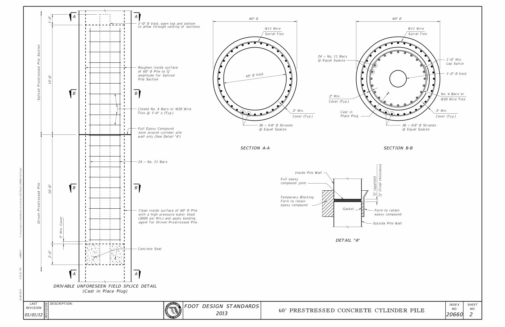
Concrete Seal
2’-
0"
3"
Min.
Cover
Driv
en Prestressed Pile
10’-
6"
24 ~ No. 11 Bars
Ties @ 1’-0" – (Typ.)
Closed No. 4 Bars or W20 Wire
Spliced Prestressed Pile Sectio
n
10’-
6"
1’-
0"
to allow through venting of sections1’-0" Ø Void, open top and bottom
agent for Driven Prestressed Pile
(3000 psi Min.) and apply bonding
with a high pressure water blast
Clean inside surface of 60" Ø Pile
Pile Section
amplitude for Spliced
" �of 60" Ø Pile to
Roughen inside surface
3" Min.
Cover (Typ.)
Spiral Ties
W11 Wire
Lap Splice
1’-0" Min.
W20 Wire Ties
No. 4 Bars or
3" Min.
Cover (Typ.)Place Plug
Cast in
Cover (Typ.)
2" Min.
@ Equal Spaces
24 ~ No. 11 Bars
Spiral Ties
W11 Wire
60" Ø
45" Ø Void
@ Equal Spaces
36 ~ 0.6" Ø Strands
60" Ø
@ Equal Spaces
36 ~ 0.6" Ø Strands
1’-0" Ø Void
Outside Pile Wall
Gasket
epoxy compound
Form to retain
Inside Pile Wall
epoxy compound
Form to retain
Temporary Blocking
DETAIL "A"
SECTION B-BSECTION A-A
(Cast in Place Plug)
DRIVABLE UNFORESEEN FIELD SPLICE DETAIL
AA
BB
BB
AA
wall only (See Detail "A")
Joint around cylinder pile
Full Epoxy Compound
̆�" (a
ppl
b" (fin
al thic
kness)
compound joint
Full epoxy
01/01/12 20660 2
60" PRESTRESSED CONCRETE CYLINDER PILE