PRESSURISATION CONTROL SYSTEMS · SODECA focuses its business activity on the manufacture of in-...
24
EN-12101-6 Smoke and heat control systems: Specifications for differential pressure systems Certified: NR331151 PRESSURISATION CONTROL SYSTEMS FOR STAIRCASES, FIRE-FIGHTING LOBBIES AND ESCAPE ROUTES KIT BOXPDS HATCH PDS PRESSKIT KIT SOBREPRESIÓN · CAN BE EASILY AND QUICKLY INSTALLED · MOUNTED USING COMPLETE MODULES OR KIT · INTEGRATED SOLUTION · UNIT FULLY CALIBRATED AND TESTED · FAST REACTION UNITS FOR CHAOTIC EVACUATIONS
Transcript of PRESSURISATION CONTROL SYSTEMS · SODECA focuses its business activity on the manufacture of in-...

EN-12101-6Smoke and heat control systems: Specifications for differential pressure systems
Certified: NR331151
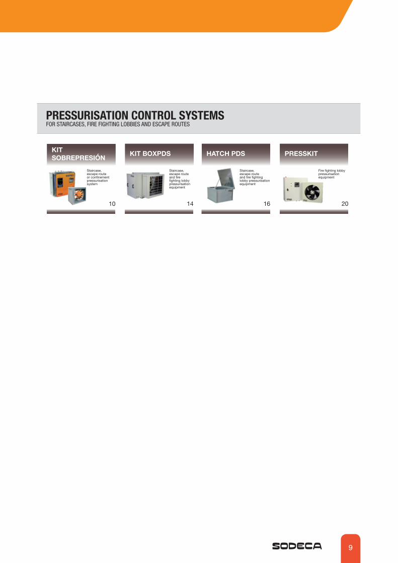
PRESSURISATION CONTROL SYSTEMSFOR STAIRCASES, FIRE-FIGHTING LOBBIES AND ESCAPE ROUTES
KIT BOXPDS
HATCH PDS
PRESSKIT
KIT SOBREPRESIÓN
· CAN BE EASILY AND QUICKLY INSTALLED
· MOUNTED USING COMPLETE MODULES OR KIT
· INTEGRATED SOLUTION
· UNIT FULLY CALIBRATED AND TESTED
· FAST REACTION UNITS FOR CHAOTIC EVACUATIONS

SODECA focuses its business activity on the manufacture of in-dustrial fans, ventilation systems and smoke extractor fans for fire protection since it was set up in 1983.
The fans and extractor fans manufactured by SODECA are pre-sent in Europe and in many other parts of the world due to their quality and the research and development methods used.
Our quality procedures, certified by BUREAU VERITAS in accord-ance with ISO 9001:2008, are another reason why SODECA is positioned as one of the best and most recognised fan manufac-turer in Europe.
There is no doubt that the most important element in achieving our objectives is the human factor and the professionals who work in the company and offer not only ventilation equipment but solu-tions to all the needs of our customers in the ventilation sector.
We offer them the option of visiting our facilities in Sant Quirze de Besora, with a developed surface area of more than 16,000 m2, to see our fan production plant, which complies with the highest quality requirements and with the ISO and AMCA standards.
This catalogue contains just a few of all the options we offer. Please contact us and we will place all our experience and staff at your disposal.
Headquarters of SODECA S.L.U., in Sant Quirze de Besora
Sodeca has embarked on a new phase of studying and de-signing new ventilation trends to help protect the environment and save energy, both matters of great concern for modern society.
SODECA presents its new “Effi-cient Work” high performance fans, fitted with next-generation motors to obtain higher energy savings. These new products ex-ceed the requirements of the ErP 2009/125/CE Ecodesign Direc-tive and its regulating provisions (EU) 327/2011 for fans, collabo-rating with the EU KYOTO Proto-col objective of reducing carbon emissions.
OUR COMMITMENT TO THE ENVIRONMENT
EFFICIENT WORK
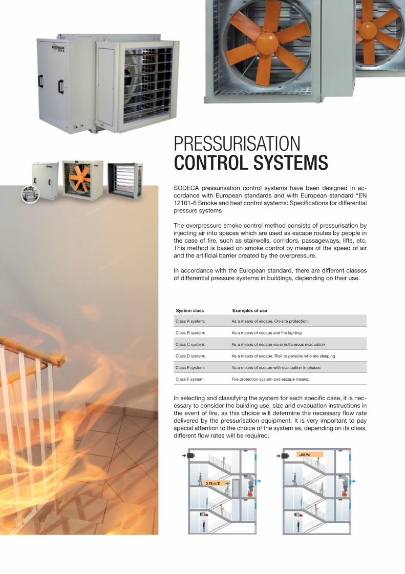
SODECA pressurisation control systems have been designed in ac-cordance with European standards and with European standard “EN 12101-6 Smoke and heat control systems: Specifications for differential pressure systems
The overpressure smoke control method consists of pressurisation by injecting air into spaces which are used as escape routes by people in the case of fire, such as stairwells, corridors, passageways, lifts, etc. This method is based on smoke control by means of the speed of air and the artificial barrier created by the overpressure.
In accordance with the European standard, there are different classes of differential pressure systems in buildings, depending on their use.
+50 Pa
0.75 m/S
Class A system: As a means of escape. On-site protection:
Class B system: As a means of escape and fire fighting
Class C system: As a means of escape via simultaneous evacuation
Class D system: As a means of escape. Risk to persons who are sleeping
Class E system: As a means of escape with evacuation in phases
Class F system: Fire protection system and escape means:
System class Examples of use
In selecting and classifying the system for each specific case, it is nec-essary to consider the building use, size and evacuation instructions in the event of fire, as this choice will determine the necessary flow rate delivered by the pressurisation equipment. It is very important to pay special attention to the choice of the system as, depending on its class, different flow rates will be required.
PRESSURISATION CONTROL SYSTEMS

4
CLASS B SYSTEMA class B differential pressure system may be used to minimise the possibility of serious smoke contamination of the fire control sta-tions during the evacuation of persons and while the fire fighters are extinguishing the fire.
During the extinguishing operations, it will be necessary to open the door between the lobby and the living quarters to fight a po-tentially developed fire.
CLASS C SYSTEMClass C systems are designed for all the occupants of the building to be evacuated at once when the fire alarm is activated.
In the case of a simultaneous evacuation, it is assumed that the stairs will be occupied for the normal evacuation period and then be free of people. Thus, the evacuation will take place during the first stages of the fire development, and during this period, it is accepted that a certain volume of smoke may reach the staircase.
The air flow contributed by the pressurisation system can eliminate that smoke from the staircase.
It is assumed that during the evacuation, the occupants will remain alert and ready, and be familiar with the area in which they are moving, with the ensuing reduction of the time they remain inside the building.
CLASS A SYSTEMThe project conditions are based on assuming that the building will not be evacuated unless it is directly threatened by the fire.
The level of compartmentalisation of the fire is normally safe for the occupants who remain inside the building.
Therefore it is not very likely that more than one door will be open at the same time in the protected space (either between the stairs and the lobby / corridor or the final exit door).
1. Door open2. Door closed3. Air emission flow *An open door may indicate a free passage of air through one lobby
1. Fire stairs2. Fire fighting lobbies3. Door open4. Door closed5. Air exhaust openings
6. Door open (fire fighting lobbies)7. Door closed (fire fighting lobbies)8. Air flow from fire fighter lift shaft
1. Door open2. Door closed3. Air exhaust openings *The figure may include lobbies
SYSTEM CLASS
Air flow criterion Differential pressure criterion (all the doors closed)
1 3 3
2
0.75 m/S 50 Pa
Air flow criterion Differential pressure criterion (all the doors closed)
5 5
6
7
8
2 2
3
1 1
4
50 Pa
45 Pa2.0 m/S
Air flow criterion Differential pressure criterion Differential pressure criterion (all the doors closed)
1
1
2 2
3 3 310 Pa 50 Pa
0.75 m/S

5
CLASS E SYSTEMThey are used in buildings where fire evacuation is done by phases or as staggered evacuations.
In “evacuation by phases” it is considered that the building would still be occupied for a considerable time while the fire is devel-oping, and so higher fire loads must be considered and hence, a larger volume of smoke and hot gases. (These factors may vary considerable, depending on the type of material in combustion, the fire load generated by them and the load geometry).
In such a situation, the protected staircases must be kept free of smoke to allow the safe evacuation of the people occupying the floors where there is no fire.
CLASS F SYSTEMClass F differential pressure systems are used to minimise the possibility of serious smoke contamination of the staircases that are used by fire fighters while the building is being evacuated and while the fire fighters are extinguishing the fire.
During the extinguishing operations, it will be necessary to open the door between the lobby and the living quarters to fight a po-tentially developed fire.
This system must be designed so that the stairwell and lift shaft (if any) remain free of smoke. If the smoke enters the lobby, the staircase pressure must not lead the smoke to the shaft, and vice versa.
CLASS D SYSTEMClass D systems are designed for buildings where the occupants may be sleeping, for example, hotels, shelters and boarding es-tablishments. The time necessary for the occupants to move in a protected space before reaching the final exit may be longer than that expected in the case of persons who are awake and in good physical condition, and the occupants may not be familiar with the building or need help to reach the final exit / protected space.
1. Door open2. Door closed3. Air exhaust openings *The figure may include lobbies
1. Door open2. Door closed3. Air exhaust openings *The figure may include lobbies
1. Staircase2. Lobby3. Living quarters4. External air supply5. Door gratings, etc.6. Air exhaust openings from the building to the exterior7. Overpressure hatch for dis-charging air to the exterior8. Living quarters9. Lift landing10. Lift cabin
Air flow criterion Differential pressure criterion Differential pressure criterion (all the doors closed)
2
2
2
1
1
3 3 310 Pa 50 Pa
0.75 m/S
Air flow criterion Differential pressure criterion Differential pressure criterion (all the doors closed)
2
1
1
2
3 3 3
2
10 Pa 50 Pa
0.75 m/S
4 4
4 4
1 12 23
6 6
95
3
8 86
7 710 1095
0Pa 0Pa
50Pa 50Pa50Pa 50Pa
50Pa 50Pa
50Pa
4 4
6
6
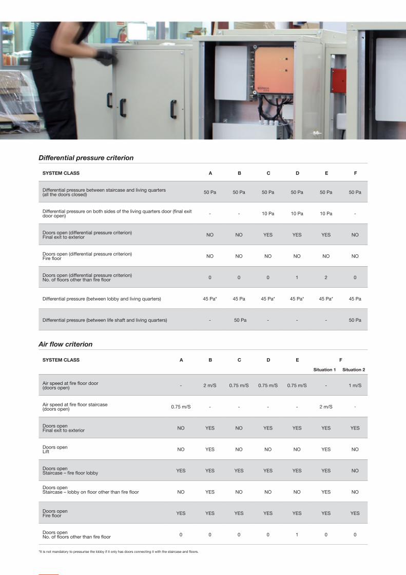
Differential pressure between staircase and living quarters (all the doors closed) 50 Pa 50 Pa 50 Pa 50 Pa 50 Pa 50 Pa
Differential pressure on both sides of the living quarters door (final exit door open) - - 10 Pa 10 Pa 10 Pa -
Doors open (differential pressure criterion)Final exit to exterior NO NO YES YES YES NO
Doors open (differential pressure criterion)Fire floor NO NO NO NO NO NO
Doors open (differential pressure criterion)No. of floors other than fire floor 0 0 0 1 2 0
Differential pressure (between lobby and living quarters) 45 Pa* 45 Pa 45 Pa* 45 Pa* 45 Pa* 45 Pa
Differential pressure (between life shaft and living quarters) - 50 Pa - - - 50 Pa
Differential pressure criterion
SYSTEM CLASS A B C D E F
SYSTEM CLASS A B C D E F
Air speed at fire floor door (doors open) - 2 m/S 0.75 m/S 0.75 m/S 0.75 m/S - 1 m/S
Air speed at fire floor staircase (doors open) 0.75 m/S - - - - 2 m/S -
Doors openFinal exit to exterior NO YES NO YES YES YES YES
Doors openLift NO YES NO NO NO YES NO
Doors openStaircase – fire floor lobby YES YES YES YES YES YES NO
Doors openStaircase – lobby on floor other than fire floor NO YES NO NO NO YES NO
Doors openFire floor YES YES YES YES YES YES YES
Doors openNo. of floors other than fire floor 0 0 0 0 1 0 0
Air flow criterion
*It is not mandatory to pressurise the lobby if it only has doors connecting it with the staircase and floors.
Situation 1 Situation 2

7
Response timeAll the systems must be designed so that the force to be applied to the door handle to open it does not exceed 100N.
The SODECA equipment has next-generation, built-in controls that meet the most stringent requirements and are extremely reliable in the face of changes in situation that may occur during a fire, and in “chaotic” evacuation situations in which doors between fire zones and in pressurised smoke-free areas are opened and closed at random. Our systems react quickly and precisely to such changes, always en-suring an Overpressure of 50Pa for closed doors and maintaining the required air speed in each open door situation. This response capacity guarantees that the force used to open a door does not exceed 100N, as set out in European standards.
The SODECA equipment fully complies with the following reaction times:
The SODECA systems offer different types of equipment to satisfy all installation needs, depending on the building in which the pressurisation control system is used.
Examples of application
BOXPDS KIT / HATCH PDS / KIT SOBREPRESIÓN
On the roof
BOXPDS KIT / KIT SOBREPRESIÓN
In technical room
PRESSKIT / KIT SOBREPRESIÓN
In separate lobby
When selecting the equipment, it is important to consider where it will be installed and determine how the external air will enter and its deliv-ery to the pressurised zone, based on the following recommendations:
Intake of external airThe external air inlet must be far from areas where there is a risk of fire, to ensure the entry of clean air through the pressurisation system. In the event of an indoor installation, two air intakes will be needed, at a considerable distance from each other, and fitted with smoke detec-tion systems so that if smoke enters through one of the nozzles, it can be closed automatically by a motorised damper (DAMPER KIT) or another equivalent system.
Delivery of air to the interiorA single air delivery point to the pressurised zone is accepted for buildings less than 11 metres in height. For taller buildings, an air entry point must be provided for every three floors, using for example diffus-ers and an air conduit throughout the entire staircase.
t0 t1 t2 t3 t4 t[s]
p
ptraus
pnom
nom
90¼
Q
Q
Q
Movement of the door
Open door
t1: Opening of door (1 second)t2: Door open The system delivers 100% of the necessary flow rate in less than 6 secondst3: Closing of door (3 seconds)
t4: Door closed The system acquires the nominal pressure in less than 6 seconds, thus preventing pro-longed excess pressure and ensuring that the force used on the door handle is no greater than 100N. Q= Flow rate P= Pressure

8
All the equipment manufactured by SODECA is subject to stringent tests in real-life simulations using our installations and our test cam-era with fire doors, motorised dampers for leakage simulation and fire rated door opening/closing operations, in accordance with standard EN-12101-6 Smoke and heat control systems: Specifications for dif-ferential pressure systems
SODECA goes one step further, adapting to new market needs and of-fering a response to new technological demands. Our systems include advanced options and connectivity to facilitate the supervision and maintenance of the equipment, once installed in any building.
Any BMS (Building Management System) system can be connected to our equipment via the Modbus protocol, allowing end users or main-tenance services to supervise the status and correct operation of the systems at all times.
Equipment certified by independent laboratories
REAL-LIFE SIMULATION TESTS
REMOTE CONNECT START CONTROL
Certified: NR331151
EN-12101-6Smoke and heat control systems: Specifications for differential pressure systems
9
KIT SOBREPRESIÓN
10
Staircase, escape route or confinement pressurisation system
PRESSKIT
20
Fire fighting lobby pressurisation equipment
KIT BOXPDS
14
Staircase, escape route and fire fighting lobby pressurisation equipment
HATCH PDS
16
Staircase, escape route and fire fighting lobby pressurisation equipment
PRESSURISATION CONTROL SYSTEMS FOR STAIRCASES, FIRE FIGHTING LOBBIES AND ESCAPE ROUTES

10
STAIRCASE OVERPRESSURE KITFor three-phase equipment
OVERPRESSURE KIT WITH RESERVE FAN
The staircase, escape route or confinement pressurisation system enables automatic control of the flow rate and the maintenance of a differential pressure of 50 Pa in a single phase, based on stand-ard UNE EN 12101-6-2006
KIT SOBREPRESIÓNSTAIRCASE OVERPRESSURE KIT• Overpressure kit comprised of a control panel (BOXPRES KIT) and discharge units (CJHCH or
CJBD), for pressurising staircases and escape routes. Also available for NEOLINEO AND CJBC single-phase equipment.
OVERPRESSURE KIT WITH RESERVE FAN• Overpressure kit comprised of a control panel (BOXPRES KIT II) with a built-in automatic
switching system that maintains the overpressure in the event of a failure in the main fan and air discharge units with a TWIN or CJHCH/DUPLEX series reserve fan.
BOXPRES
• The correct operation of the pressurisation systems depends not only on their sound design, but on the correct regulation performed by the system. For this reason, it is extremely important to have calibrated, high precision regulation elements that will permit both situations present in the event of a fire to be maintained simultaneously, quickly and stably.
• The BOXPRES control panel not only complies with the strictest requirements, it simplifies the work for the installer.
It includes:• A frequency changer programmed at 50 Pa.• A differential pressure sensor.• A magneto thermal switch.• A line and failure led lamp.• A check push button.
BOXPRES:• All the equipment interconnections are made and tested.• Ready to operate and execute its mission of controlling the installation pressure.• Option of checking the installation to prevent failures.• Only the power supply line, discharge fan and fire signal need to be connected.
The single-phase panels include:• A voltage adjuster programmed at 50 Pa.• A differential pressure sensor outside the equipment.
· Easy to install· A compact, autonomous solution· Preventive maintenance· Easy start-up· Safe, functional installation
Order code
KIT SOBREPRESIÓN 7.100
Kit sobrepresión Staircase overpressure unitKit sobrepresión II: Overpressure unit with reserve fan
Maximum flow rate
STAIRCASE OVERPRESSURE KIT For single-phase equipment
11
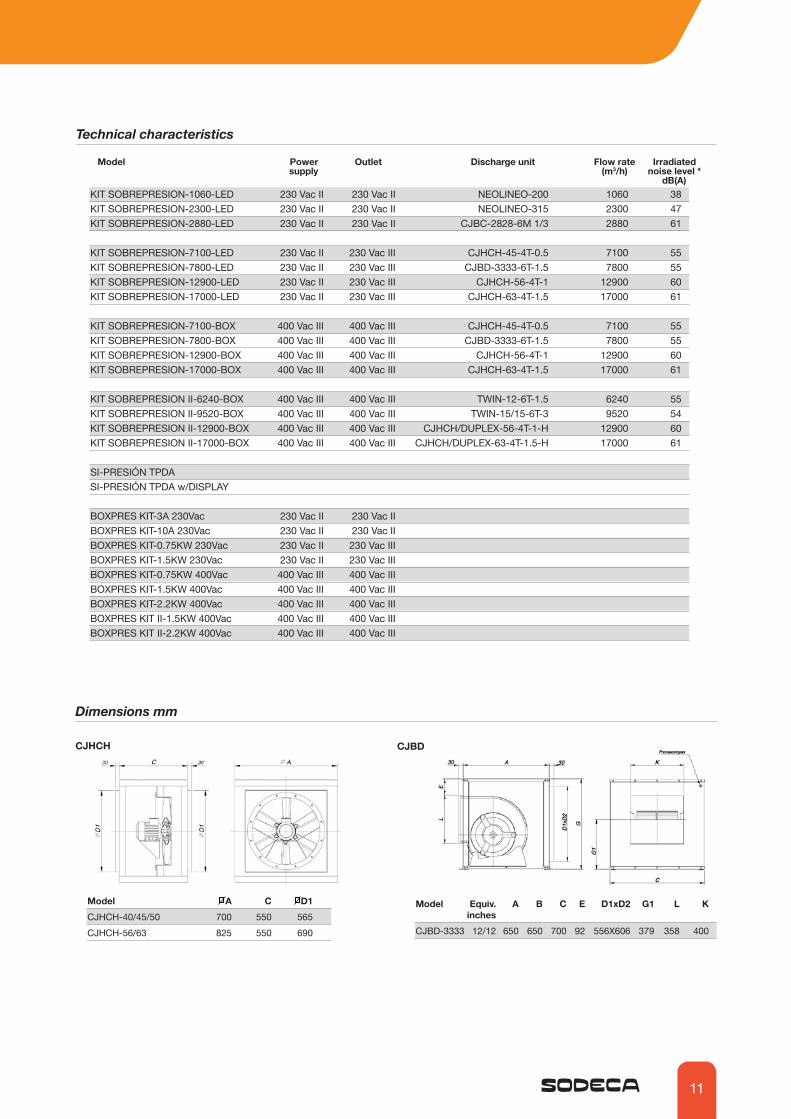
Technical characteristics
Model Power supply
Flow rate(m3/h)
Irradiatednoise level *
dB(A)
Dimensions mm
Model A C D1 CJHCH-40/45/50 700 550 565CJHCH-56/63 825 550 690
CJHCH CJBD
Model Equiv. A B C E D1xD2 G1 L K inchesCJBD-3333 12/12 650 650 700 92 556X606 379 358 400
Discharge unitOutlet
KIT SOBREPRESION-1060-LED 230 Vac II 230 Vac II NEOLINEO-200 1060 38KIT SOBREPRESION-2300-LED 230 Vac II 230 Vac II NEOLINEO-315 2300 47KIT SOBREPRESION-2880-LED 230 Vac II 230 Vac II CJBC-2828-6M 1/3 2880 61 KIT SOBREPRESION-7100-LED 230 Vac II 230 Vac III CJHCH-45-4T-0.5 7100 55KIT SOBREPRESION-7800-LED 230 Vac II 230 Vac III CJBD-3333-6T-1.5 7800 55KIT SOBREPRESION-12900-LED 230 Vac II 230 Vac III CJHCH-56-4T-1 12900 60KIT SOBREPRESION-17000-LED 230 Vac II 230 Vac III CJHCH-63-4T-1.5 17000 61 KIT SOBREPRESION-7100-BOX 400 Vac III 400 Vac III CJHCH-45-4T-0.5 7100 55KIT SOBREPRESION-7800-BOX 400 Vac III 400 Vac III CJBD-3333-6T-1.5 7800 55KIT SOBREPRESION-12900-BOX 400 Vac III 400 Vac III CJHCH-56-4T-1 12900 60KIT SOBREPRESION-17000-BOX 400 Vac III 400 Vac III CJHCH-63-4T-1.5 17000 61
KIT SOBREPRESION II-6240-BOX 400 Vac III 400 Vac III TWIN-12-6T-1.5 6240 55KIT SOBREPRESION II-9520-BOX 400 Vac III 400 Vac III TWIN-15/15-6T-3 9520 54KIT SOBREPRESION II-12900-BOX 400 Vac III 400 Vac III CJHCH/DUPLEX-56-4T-1-H 12900 60KIT SOBREPRESION II-17000-BOX 400 Vac III 400 Vac III CJHCH/DUPLEX-63-4T-1.5-H 17000 61
SI-PRESIÓN TPDASI-PRESIÓN TPDA w/DISPLAY BOXPRES KIT-3A 230Vac 230 Vac II 230 Vac II BOXPRES KIT-10A 230Vac 230 Vac II 230 Vac II BOXPRES KIT-0.75KW 230Vac 230 Vac II 230 Vac III BOXPRES KIT-1.5KW 230Vac 230 Vac II 230 Vac IIIBOXPRES KIT-0.75KW 400Vac 400 Vac III 400 Vac IIIBOXPRES KIT-1.5KW 400Vac 400 Vac III 400 Vac IIIBOXPRES KIT-2.2KW 400Vac 400 Vac III 400 Vac IIIBOXPRES KIT II-1.5KW 400Vac 400 Vac III 400 Vac IIIBOXPRES KIT II-2.2KW 400Vac 400 Vac III 400 Vac III

12
Model A B CTWIN-12/12 1103 1139 610TWIN 15/15 1279 1639 698
TWIN CJHCH/DUPLEX
Model A B C D1 CJHCH/DUPLEX-56/63 825 1650 550 690
BOXPRESS KIT SOBREPRESIÓN
Technical characteristics and dimensions
Model PowerkW
Power supply(V/Hz)
Outlet current (A)
Outlet(V/Hz)
Size Measurements(length x width x depth)
BOXPRES KIT-3A 230Vac - 230 Vac II 230 Vac II 3 - 255 x 170 x 140 mmBOXPRES KIT-10A 230Vac - 230 Vac II 230 Vac II 10 - 255 x 170 x 140 mm BOXPRES KIT-0.75kW 230Vac 0.75 230 V II / 50Hz 230 V III / 50Hz 4.3 1 270 x 270 x 170 mmBOXPRES KIT-1.5kW 230Vac 1.5 230 V II / 50Hz 230 V III / 50Hz 7 1 270 x 270 x 170 mmBOXPRES KIT-0.75KW 400Vac 0.75 400 V III / 50Hz 400 V III / 50Hz 2.2 1 270 x 270 x 170 mmBOXPRES KIT-1.5KW 400Vac 1.5 400 V III / 50Hz 400 V III / 50Hz 4.1 1 270 x 270 x 170 mmBOXPRES KIT-2.2KW 400Vac 2.2 400 V III / 50Hz 400 V III / 50Hz 5.8 2 360 x 360 x 205 mm
M 20 x 1.5mmPower supply and motor connection
M 12 x 1.5mmFire signal connection
Pressure connection
BOXPRES KIT-3A / KIT-10A
Power supply and motor connection
Regulator
Sensor
Pressure connection
Dimensions mm
NEOLINEO CJBC
Model A B H K L øO V v1 X x1CJBC-2828-6M-1/3 696 645 460 290 320 15 755 725 445 100
Model A B C C1 C2 øD ENEOLINEO-200 300 234.5 260.5 125.5 235 196 140NEOLINEO-315 448 361.5 392.5 188.5 359 312 220.5
Equipment cable entry gland
BOXPRES KIT size 1 and 2

13
Example of application
The overpressure smoke control method consists of pressurisation by injecting air into spaces which are used as escape routes by people in the case of fire, such as stairwells, corridors, passageways, lifts, etc., especially in tall buildings with large occupancy. The method is based on smoke control by the air speed and the artificial barrier created by air overpressure, prevent-ing it from entering the escape routes.
BOXPRESS KIT SOBREPRESIÓN II
Technical characteristics and dimensions
Model PowerkW
Power supply(V/Hz)
Outlet current (A)
BOXPRES KIT II - 1.5KW 400Vac 1.5 400 V III / 50Hz 400 V III / 50Hz 4.1 1 270 x 270 x 170 mmBOXPRES KIT II - 2.2KW 400Vac 2.2 400 V III / 50Hz 400 V III / 50Hz 5.4 2 360 x 360 x 205 mm
Outlet(V/Hz)
Size Measurements(length x width x depth)
For equipment with a reserve fan
* Both motors will never operate simultaneously
M 20 x 1.5mmPower supply and motor connection
M 12 x 1.5mmFire signal connection
Pressure connection
Equipment cable entry gland
BOXPRES KIT size 1 and 2

14
KIT BOXPDSPressurisation equipment for escape routes in the event of a fire, pursuant to the requirements of European standard EN 12101-6. The BOXPDS KIT automatically regulates the air flow and is able to maintain the 50 Pa over-pressure, even in the present of leakages in the installation. The system can maintain the overpressure (pressure criteria) and a speed of 0.75 m/s in an open door situation (airflow criteria) almost immediately.
KIT BOXPDS• It is comprised of the BOXPDS control panel, a CJHCH ventilation unit
and a Damper Kit with a built-in optical smoke sensor.
BOXPDS• Variable Frequency Drive.• High precision differential pressure sensor.• Electric panel with magneto thermal protections
and general power supply failure indication.• Electronic control for the management of alarms,
maintenance, ModBUS RTU port for BMS (Building management systems) connection and DAMPER control.
• Certified power supply with batteries to ensure power supply to control equipment in the event of a power failure.
Control panel: • External control panel for real-time
viewing of pressure, alarm pilot lamps and manual system activation
· Easy to install· A compact, autonomous solution· Preventive maintenance· Easy start-up· Safe, functional installation
Order code
KIT BOXPDS 800 5.5
Pressurisation equipment for staircases, escape routes and fire fighting lobbies
Power (HP)
Fan diameter
Technical characteristics
BOXPDS-710-1.5 1400 2.32 1.1 19750 75 188BOXPDS-710-2 1430 3.44 1.5 21100 75 190.5BOXPDS-710-3 1445 4.83 2.2 23950 78 200BOXPDS-800-3 1445 4.83 2.2 28000 79 208BOXPDS-800-4 1445 6.33 3 32700 80 210BOXPDS-800-5.5 1440 8.12 4 37200 81 215
Model Speed Max. admissible cur-rent 400V
Installed power
Maximum flow rate Irradiated NPS Approx. weight
(r/min) (A) (kW) (m3/h) dB(A) (Kg)
Pressurisation equipment for staircases, escape routes and fire fighting lobbies, pursuant to European standard EN 12101-6
BOXPDS
+50 Pa +50 Pa

15
Dimensions mm
Model A C D1 CJHCH-71/80 1000 650 850
BOXPDS CJHCHDAMPER
Examples of application
Two dampers can be used by installing two intake points at a considerable dis-tance from the fan, so that one of the points is always in the open position and the other closed. In the event of smoke being detected in the intake nozzle with an open damper, the damper closes and the second damper opens to ensure the entry of clean air into the space to be protected (smoke-free escape route).
BOXPDS DAMPER
Next to ventilation unitIn technical room Next to ventilation unitIn intake conduit
KIT BOXPDS
Model A B C BOXPDS 900 650 280
Model A B C DAMPER 995 326.5 855
16
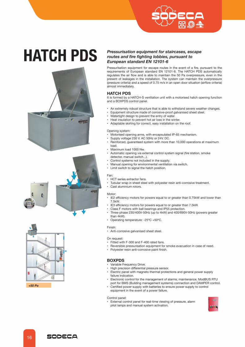
HATCH PDS Pressurisation equipment for staircases, escape routes and fire fighting lobbies, pursuant to European standard EN 12101-6Pressurisation equipment for escape routes in the event of a fire, pursuant to the requirements of European standard EN 12101-6. The HATCH PDS automatically regulates the air flow and is able to maintain the 50 Pa overpressure, even in the present of leakages in the installation. The system can maintain the overpressure (pressure criteria) and a speed of 0.75 m/s in an open door situation (airflow criteria) almost immediately.
HATCH PDSIt is formed by a HATCH-S ventilation unit with a motorised hatch opening function and a BOXPDS control panel.
• An extremely robust structure that is able to withstand severe weather changes.• Equipment structure made of corrosive-proof galvanised sheet steel.• Watertight design to prevent the entry of water.• Heat insulation to prevent hot air loss in the winter.• Adaptable skirting for correct, easy installation on the roof.
Opening system:• Motorised opening arms, with encapsulated IP-65 mechanism.• Supply voltage 230 V. AC 50Hz or 24V. DC.• Reinforced, guaranteed system with more than 10,000 operations at maximum
load.• Maximum load 1000 Nw.• Automatic opening via external control system signal (fire station, smoke
detector, manual switch...). • Control systems not included in the supply.• Manual opening for environmental ventilation via switch.• Limit switch to signal the hatch position.
Fan:• HCT series extractor fans.• Tubular wrap in sheet steel with polyester resin anti-corrosive treatment.• Cast aluminium rotors.
Motor:• IE2 efficiency motors for powers equal to or greater than 0.75kW and lower than
7.5kW.• IE3 efficiency motors for powers equal to or greater than 7.5kW.• Class F motors with ball bearings and IP55 protection.• Three-phase 230/400V-50Hz (up to 4kW) and 400/690V-50Hz (powers greater
than 4kW).• Operating temperature: -25ºC +50ºC.
Finish:• Anti-corrosive galvanised sheet steel.
On request:• Fitted with F-300 and F-400 rated fans.• Reversible pressurisation equipment for smoke evacuation in case of need.• Polyester resin anti-corrosive paint finish.
BOXPDS• Variable Frequency Drive.• High precision differential pressure sensor.• Electric panel with magneto thermal protections and general power supply
failure indication.• Electronic control for the management of alarms, maintenance, ModBUS RTU
port for BMS (Building management systems) connection and DAMPER control.• Certified power supply with batteries to ensure power supply to control
equipment in the event of a power failure.
Control panel: • External control panel for real-time viewing of pressure, alarm
pilot lamps and manual system activation.
+50 Pa

17
Technical characteristics
Maximum admissible current(A)
230V 400V 690V
Installed power(kW)
Maximum flow rate
(m3/h)
Speed(r/min)
Sound pres-sure level
dB(A)
Approx.weight
(Kg)
Model
HATCH PDS-40-2T-1 2850 3.15 1.80 0.75 6115 72 184HATCH PDS-40-2T-1.5 2880 4.70 2.70 1.10 7050 73 188HATCH PDS-45-2T-2 2880 5.90 3.40 1.50 9405 75 193HATCH PDS-45-2T-3 2840 8.70 5.00 2.20 11325 77 194HATCH PDS-50-2T-2 2880 5.90 3.40 1.50 10100 77 197HATCH PDS-50-2T-3 2840 8.70 5.00 2.20 11925 78 199HATCH PDS-50-2T-4 2880 11.20 6.50 3.00 13860 79 206HATCH PDS-50-2T-5.5 2870 9.30 5.40 4.00 15900 80 222HATCH PDS-56-2T-5.5 2870 9.50 5.50 4.00 18840 85 226HATCH PDS-56-2T-7.5 2910 10.60 6.14 5.50 22510 86 237HATCH PDS-56-2T-2 1440 6.20 3.60 1.50 15020 72 205HATCH PDS-63-2T-3 1425 9.00 5.20 2.20 22460 73 262HATCH PDS-63-2T-4 1430 11.40 6.60 3.00 24460 74 271HATCH PDS-63-2T-1 940 4.70 2.70 0.75 16025 63 252HATCH PDS-80-2T-3 1425 9.00 5.20 2.20 25545 79 280HATCH PDS-80-2T-4 1430 11.40 6.60 3.00 30410 80 289HATCH PDS-80-2T-5.5 1440 8.40 4.80 4.00 32940 81 295HATCH PDS-80-2T-7.5 1460 12.60 7.30 5.50 39820 82 311HATCH PDS-80-2T-1.5 945 5.50 3.20 1.10 21580 69 279HATCH PDS-80-2T-2 945 7.40 4.30 1.50 26090 70 288HATCH PDS-90-2T-7.5 1460 12.60 7.30 5.50 46325 88 392HATCH PDS-90-2T-10 1460 17.70 10.20 7.50 50315 89 403HATCH PDS-90-2T-15 1460 22.00 12.70 11.00 59610 90 456HATCH PDS-90-2T-3 950 9.50 5.50 2.20 34055 75 365HATCH PDS-90-2T-4 970 13.50 7.80 3.00 39055 76 391HATCH PDS-100-2T-10 1460 17.70 10.20 7.50 57650 90 413HATCH PDS-100-2T-15 1460 22.00 12.70 11.00 66505 91 466HATCH PDS-100-2T-5.5 970 11.00 6.40 4.00 47955 81 413HATCH PDS-100-2T-7.5 970 12.40 7.20 5.50 53545 82 420
Technical characteristics of the dynamic discharge system based on standard EN 12101-3:2002/AC:2006
HATCH PDS - Class F RE 10000 T(-15) WL 1500 SL 500
Model Approval °C Motor insulation class
Durability Minimum room temperature
Wind load (Pa) Snow load (Pa)
HATCH PDS 80 4T 5.5 N 1 G
Order code
SizeModel Number of motor poles2=2900 r/min. 50 Hz4=1400 r/min. 50 Hz6=900 r/min. 50 Hz
T=Three-phase Motorpower (HP)
Electric accessoriesN= no accessoriesY= Limit switch
Opening system supply voltage1=230 V.AC2=24 V.DC
FinishG=galvanisedP=painted in special colour

18
The values given are determined by measuring the sound power in dB(A) obtained in a free field at a distance equivalent to twice the size of the fan plus the rotor diameter, with a minimum of 1.5 m.
Acoustic characteristics
Sound power spectrum Lw(A) in dB(A) per Hz frequency band.Model 63 125 250 500 1000 2000 4000 800040-2-1 44 65 72 77 80 76 69 5840-2-1.5 45 66 73 78 81 77 70 5945-2-2 47 68 75 80 83 79 72 6145-2-3 49 70 77 82 85 81 74 6350-2-2 52 72 80 85 87 84 77 6650-2-3 53 73 81 86 88 85 78 6750-2-4 54 74 82 87 89 86 79 6850-2-5.5 55 75 83 88 90 87 80 6956-2-5.5 60 80 88 93 95 92 85 7456-2-7.5 61 81 89 94 96 93 86 7556-4-2 47 67 75 80 82 79 72 6163-4-3 50 68 76 81 83 80 75 6463-4-4 51 69 77 82 84 81 76 6563-6-1 41 60 68 73 75 72 65 5580-4-3 56 75 83 89 90 87 81 70
80-4-4 54 74 82 87 89 86 79 7180-4-5.5 54 74 82 87 89 86 79 7280-4-7.5 55 75 83 88 90 87 80 7380-6-1.5 47 64 72 77 79 76 69 5880-6-2 48 65 73 78 80 77 70 5990-4-7.5 57 78 85 90 93 89 82 7190-4-10 56 77 84 89 92 88 81 7090-4-15 58 79 86 91 94 90 83 7290-6-3 54 68 75 80 83 79 72 6190-6-4 55 70 77 82 85 81 74 63100-4-10 60 80 88 93 95 92 85 74100-4-15 59 79 87 92 94 91 84 73100-4-20 61 81 89 94 96 93 86 75100-6-5.5 62 71 79 84 86 83 76 65100-6-7.5 63 72 80 85 87 84 77 66
Model 63 125 250 500 1000 2000 4000 8000
Erp. Maximum efficiency point (BEP) characteristics
MCModel EC VSD SR ηe[%] N (kW) (m3/h) (mmH2O) (RPM)
<(º) Blade inclination angle (degrees) PN Nominal motor power (kW) MC Measurement categoryEC Efficiency category S Static T TotalVSD Variable speed drive
SR Specific ratioηe[%] EfficiencyN Efficiency grade[kW] Electric power[m3/h] Flow rate[mmH2O] Static or total pressure (based on EC)[RPM] Speed
<(º) PN
HATCH PDS-40-2T-1 16 0.75 A S NO 1.00 41.5% 48.1 0.933 4420 32.19 2850 HATCH PDS-40-2T-1.5 20 1.1 A S NO 1.00 33.6% 38.9 1.445 5180 34.43 2884 HATCH PDS-45-2T-2 16 1.5 A S NO 1.00 35.9% 40.8 1.688 6802 32.70 2896 HATCH PDS-45-2T-3 22 2.2 A S NO 1.01 37.7% 41.6 2.405 8144 40.86 2854 HATCH PDS-50-2T-2 8 1.5 A S NO 1.00 35.9% 40.3 2.014 6731 39.48 2876 HATCH PDS-50-2T-3 12 2.2 A S NO 1.01 36.8% 40.5 2.586 7884 44.29 2843 HATCH PDS-50-2T-4 16 3 A S NO 1.01 34.3% 37.3 3.381 8962 47.55 2885 HATCH PDS-50-2T-5.5 20 4 A S NO 1.01 32.6% 35.1 4.131 9537 51.91 2885 HATCH PDS-56-2T-5.5 16 4 A S NO 1.01 45.4% 47.8 4.202 12896 54.34 2883 HATCH PDS-56-2T-7.5 22 5.5 A S NO 1.01 41.2% 42.6 6.055 15917 57.53 2913 HATCH PDS-56-4T-2 36 1.5 B T NO 1.00 45.7% 50.7 1.665 13581 20.60 1445 HATCH PDS-63-4T-3 32 2.2 B T NO 1.00 62.0% 65.9 2.443 20324 27.38 1430 HATCH PDS-63-4T-4 38 3 B T NO 1.00 57.8% 60.9 3.270 24239 28.64 1440 HATCH PDS-63-4T-1 38 0.75 B T NO 1.00 48.4% 54.4 1.099 15880 12.29 942 HATCH PDS-80-2T-3 12 2.2 C S NO 1.00 47.1% 51.0 2.413 16923 24.69 1430 HATCH PDS-80-2T-4 16 3 C S NO 1.00 41.1% 43.8 3.686 20444 27.19 1432 HATCH PDS-80-2T-5.5 18 4 C S NO 1.00 41.2% 43.5 4.246 22304 28.78 1448 HATCH PDS-80-4T-7.5 26 5.5 B T NO 1.00 63.0% 64.5 5.914 35186 38.92 1465 HATCH PDS-80-2T-1.5 18 1.1 C S NO 1.00 35.4% 40.8 1.389 14613 12.35 951 HATCH PDS-80-4T-2 26 1.5 B T NO 1.00 57.5% 62.1 1.825 23053 16.71 950 HATCH PDS-90-2T-7.5 18 5.5 C S NO 1.00 44.1% 45.2 6.749 31521 34.72 1460 HATCH PDS-90-2T-10 22 7.5 C S NO 1.01 38.9% 39.2 9.154 35009 37.36 1463 HATCH PDS-90-4T-15 30 11 B T NO 1.01 67.1% 67.1 11.526 52205 54.45 1463 HATCH PDS-90-2T-3 24 2.2 C S NO 1.00 38.0% 41.5 2.832 23831 16.58 950 HATCH PDS-90-4T-4 30 3 B T NO 1.00 58.8% 61.6 3.698 34203 23.37 971 HATCH PDS-100-2T-10 16 7.5 C S NO 1.00 41.3% 41.4 9.606 37591 38.73 1461 HATCH PDS-100-2T-15 22 11 C S NO 1.01 43.6% 43.5 12.145 44571 43.65 1461 HATCH PDS-100-4T-20 28 15 B T NO 1.01 64.1% 63.8 16.091 66559 56.95 1462 HATCH PDS100-6T-5.5 26 4 B T NO 1.00 57.6% 59.7 4.671 42042 23.50 973 HATCH PDS-100-4T-7.5 32 5.5 B T NO 1.00 56.3% 57.9 5.690 53520 22.00 975
19
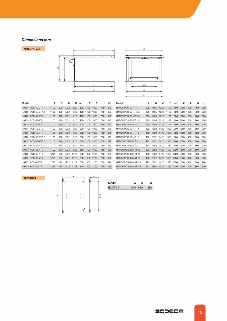
BOXPDSModel A B C BOXPDS 900 650 280
Dimensions mm
HATCH PDS-40-2T-1 1100 990 1022 920 400 1100 1000 760 820
HATCH PDS-40-2T-1.5 1100 990 1022 920 400 1100 1000 760 820
HATCH PDS-45-2T-2 1100 990 1022 920 450 1100 1000 760 820
HATCH PDS-45-2T-3 1100 990 1022 920 450 1100 1000 760 820
HATCH PDS-50-2T-2 1100 990 1022 920 500 1100 1000 760 820
HATCH PDS-50-2T-3 1100 990 1022 920 500 1100 1000 760 820
HATCH PDS-50-2T-4 1100 990 1022 920 500 1100 1000 760 820
HATCH PDS-50-2T-5.5 1100 990 1022 920 500 1100 1000 760 820
HATCH PDS-56-2T-5.5 1100 990 1022 920 560 1100 1000 760 820
HATCH PDS-56-2T-7.5 1100 990 1022 920 560 1100 1000 760 820
HATCH PDS-56-4T-2 1100 990 1022 920 560 1100 1000 760 820
HATCH PDS-63-4T-3 1295 1195 1222 1122 630 1300 1200 760 820
HATCH PDS-63-4T-4 1295 1195 1222 1122 630 1300 1200 760 820
HATCH PDS-63-6T-1 1295 1195 1222 1122 630 1300 1200 760 820
HATCH PDS-80-4T-3 1295 1195 1222 1122 800 1300 1200 760 820
HATCH PDS-80-4T-4 1295 1195 1222 1122 800 1300 1200 760 820
HATCH PDS-80-4T-5.5 1295 1195 1222 1122 800 1300 1200 760 820
HATCH PDS-80-4T-7.5 1295 1195 1222 1122 800 1300 1200 760 820
HATCH PDS-80-6T-1.5 1295 1195 1222 1122 800 1300 1200 760 820
HATCH PDS-80-6T-2 1295 1195 1222 1122 800 1300 1200 760 820
HATCH PDS-90-4T-7.5 1492 1392 1420 1320 900 1500 1400 860 920
HATCH PDS-90-4T-10 1492 1392 1420 1320 900 1500 1400 860 920
HATCH PDS-90-4T-15 1492 1392 1420 1320 900 1500 1400 860 920
HATCH PDS-90-6T-3 1492 1392 1420 1320 900 1500 1400 860 920
HATCH PDS-90-6T-4 1492 1392 1420 1320 900 1500 1400 860 920
HATCH PDS-100-4T-10 1492 1392 1420 1320 1000 1500 1400 860 920
HATCH PDS-100-4T-15 1492 1392 1420 1320 1000 1500 1400 860 920
HATCH PDS-100-4T-20 1492 1392 1420 1320 1000 1500 1400 860 920
HATCH PDS-100-6T-5.5 1492 1392 1420 1320 1000 1500 1400 860 920
HATCH PDS-100-6T-7.5 1492 1392 1420 1320 1000 1500 1400 860 920
Model A B C D ød1 E F H H1 Model A B C D ød1 E F H H1
HATCH PDS

20
Fire fighting lobby pressurisation equipment in accordance with DM 30/11/1983 and with European standard EN 12101-6PRESSKITThe PRESSKIT equipment is comprised of one or more fans. In the case of fire they are activated to exert an overpressure of 50Pa in safe zones and to prevent the entry of smoke in escape routes for the evacuation of people.
Common characteristics:• Self-regulation of pressure throughout the lobby.• Brushless 24Vdc E.C. fans with a maximum flow rate of 2100m3/H.• An overpressure of 50Pa is maintained in the lobby. Equipment control:• S models: Simplified regulation of the ventilation unit via a pressure sensor with a
built-in PID signal adjuster.• P models: PLC control with multiple inputs, outputs, alarms and fan regulation via
PID signal.• Delay in equipment connection depending on the fire door status.• Power supply panel with autonomy of more than 2 hours through 18Ah batteries. • Ease in connecting equipment.• Fast configuration and adjustment of all the parameters via LCD display and keyboard.• MANUAL system activation button.• Viewing of pressure in safe zone and equipment status in real time.
Certified: NR331151
PRESSURISATION FAN• Brushless 24VDC fan, 0-10V analogue control input.• Maximum flow rate 2100m3/h.• Mural fan for conduits with a diameter of 310mm.• ROTOR-MOTOR air direction.• Useful life in continuous operation of more than 20,000 hours.• Rotor made of painted sheet steel.• Protective anti-contact grille.
CONTROL PANEL• System control panel through small PLC that is easy to install.
Power supply 230VAC.• Digital input for detecting open door.• Digital outputs indicating fire alarm activated, through visual and
acoustic indicator light that flashes with configurable times.• Configurable connection delay times in the event of detecting a fire
alarm and fire doors open.• Configuration of all the PID output parameters.• Manual system activation button.• Viewing of pressure in Pa in real time, indication of equipment
status STANDBY/ PRESSURISING.
• Possibility of controlling 2 fans with a single panel and power source. (PRESSKIT TWIN).
• Regulation through a single control panel of 1 or 2 ventilation units.• Key lock.
Control panel characteristics Total voltage (V): 1x230 Total current (A): 0.3 Output Voltage 1 (V): 19.7-28VDC Output Voltage 2 (V): 19.7-28VDC Max. current Output 1 (A): 6 Max. current Output 2 (A): 7 Protection (IP): 44 Operating temperature (ºC): -25 to +60 Weight (Kg): 30.5
PRESSURE SENSOR WITH DISPLAY (BUILT INTO CONTROL PANEL)• 0-100 Pa preconfigured differential pressure sensor.• 0..10V analogue output.• LCD display.• Calibrated high precision analogue sensor.
+50 Pa

21
Order code
PRESSKIT ONE P
Pressurisation equipment for lobbies
Control optionsS: Single regulation P: PCL control
Kit formatONE: 1 fanTWIN 2 fan
Kit characteristics
Regulation by means of pressure sensor YES YESRegulation of several fans - YES*Relay outputs to indicate the equipment is activated YES YESDoor sensor inputs YES YES
Component PRESSKIT ONE
PRESSKIT TWIN
* PRESSKIT TWIN regulates two fans simultaneously with a single pressure sensor for large lobbies/pressurised areas. The regulation of each fan is not separate, they have the same PID set point depend-ing on the signal received from the sensor.
Configurations
E.C. FAN BRUSHLESS 24Vdc 1 unit 2 unitsCONTROL PANEL 1 unit 1 unitPRESSURE SENSOR (BUILT INTO CONTROL PANEL) 1 unit 1 unit
Component PRESSKIT ONE
PRESSKIT TWIN
Technical characteristics
PRESSKIT ONE 2100 180 1800 65 24VDC 4.8 115 6.8 42 -25 to +60 310PRESSKIT TWIN 4100 180 1800 68 24VDC 9.6 230 13.6 42 -25 to +60 310
Model Maximum flow rate
Maximum pressure Speed Irradiated
LpA 3mTotal
voltageTotal
current Total power Weight Protection Operating temperature:
Nominal diam-eter
of conduit(m3/h) (Pa) (rpm) dB(A) (V) (A) (w) (kg) (IP) (ºC) (mm)
Accessories
Alarm push button
Checkerbatteries
Dimensions mm
Power source and battery output voltage checker via RJ45 connector.
PRESSURISATION FAN CONTROL PANEL

22
[email protected] sales: [email protected]
Ctra. de Berga, km 0,7E-08580 SANT QUIRZE DE BESORABARCELONA, SPAINTel. +34 93 852 91 11+34 93 852 90 42
PREPARE TECHNICAL REPORTS IN A MATTER OF MINUTES
NEWPROJECTS MODULE
Our new tool that will help you select the product that is most appropriate for your ventilation system.
PROJECTS MODULE: a new function for preparing technical reports in a matter of minutes. . Select hundreds of models in just one step . Mass load the data into Excel . Edit and process the technical files . Print out the report with the table of contents and cover, edit it or send it to another QuickFan
CONSTANTLYUPDATED
REPORTS IN A MATTER OF
MINUTES
REPORTSCUSTOMISED
SEARCHEASY
SELECTION SOFTWARE

NEWMODELS IN
CAD 3D
Our new tool for technical departments and engineering firms will make it easy for you to select the most suitable product for your ventilation system
MODELS IN CAD 3D: . Download our fans in Cad 3D from our website . Choose from among more than 40 available Cad formats . Including Revit . More than 2,000 models and configurations available
FANSCAD 3D
FORMATSAVAILABLE
CONSTANTLYUPDATED
REPORTS IN A MATTER OF
MINUTES
PREPARE TECHNICAL REPORTS IN A MATTER OF MINUTES

SODECA. HEADQUARTERSSodeca S.L.U.Ctra. de Berga, km 0,7E-08580 SANT QUIRZE DE BESORABarcelona, SPAINTel. +34 93 852 91 11Fax: +34 93 852 90 [email protected]
PORTUGAL Sodeca Portugal LdaSr. Luiz AraújoRua Veloso Salgado 1120/11384450-801 Leça de Palmeira,Porto, PORTUGALTel. +351 229 991 100Fax: +351 229 991 [email protected]
FINLANDSodeca Finland OyMr. Kai Yli-SipiläMetsälinnankatu 30, PL2,FI-32700 Huittinen,FINLANDTel. 358 400 320 [email protected]
CHILESodeca Ventiladores LtdaSr. Francesc Bertran Avda. Puerta Sur03380 San Bernardo, Santiago, CHILETel. +56 22 840 [email protected]
ÁREA CARIBESodeca CubaSr. Carlos HernándezResidencial MiramarApto. No. 108Ave. 7ma Nº 1805 entre 18 y 20 Miramar Playa, Havana, CUBATel. 00537 20 [email protected]
PORTUGAL Sodeca Portugal LdaSr. Luiz AraújoP. E. da Granja - Pavilhão 82625-607 Vialonga,Lisboa, PORTUGALTel. +351 219 748 491 Fax. +351 219 748 [email protected]
RUSSIASodeca, L.L.C.Mr. Stanislav AlifanovRussia, 140180, Moscow region,Zhukovskiy, Myasischeva str, 1, room 603Business Сenter “Chaika”Tel:+7 495 955 90 [email protected]
Fast and flexible industrial fan solutions and tailored fansExtensive experience in smoke control systems and ATEX applicationsWide range of certified products for specific markets
HEAT RECOVERY UNITS, AIR FILTERING
AND TREATMENT UNITS
PRESSURISATION SYSTEMS FOR
HOMES
HELICAL FANS AND ROOF-MOUNTED EXTRACTOR
FANS
CENTRIFUGAL FANS AND IN-LINE EXTRACTOR
FANS
HEAVY DUTY FANSAND EXTRACTOR FANS FOR
ATEX AND EXPLOSIVE ATMOSPHERES
AIR CURTAINS FOR COMMERCIAL AND INDUSTRIAL
APPLICATIONS
SMOKE EXTRACTOR
FANS
EFFICIENT WORK FANS
ASK USFOR INFORMATIONwww.sodeca.com
Distributed by: