Pressure Sensors Product Catalogue Metallux...400 ± 0.15 ± 0.3 / 0.6 ≥ 700 ≤ 550 −1 600 ±...
24
PRESSURE SENSORS CPS 1184 CPS 2184 SPS 1000 Z SPS 3003 FIRST IN SENSORS
Transcript of Pressure Sensors Product Catalogue Metallux...400 ± 0.15 ± 0.3 / 0.6 ≥ 700 ≤ 550 −1 600 ±...

PRESSURE SENSORS
CPS 1184 CPS 2184 SPS 1000 Z SPS 3003
FIRST IN SENSORS

F I R S T I N S E N S O R S
Whether standard or customised
solutions, we offer a broad range
of pressure sensor versions.
TRUST THE X!
Welcome to Metallux USA, Inc.
Metallux USA, Inc. is the sole distributor of products for Metallux AG in Germany. A company that is internationally renowned for its sensor products.
We are located in Western New York State in the city of Rochester on the south-ern shore of Lake Ontario. The City is the home of internationally-recognized academic institutions like the University of Rochester and Rochester Institute of Technology. Metallux USA, by virtue of our sole relationship status with Germany, allows us to possess a direct line of communication with the head office in Germany. This line provides customer and potential customers the ability to receive prompt and accurate answers to all of their technical inquire.
Whether you are interested in industrial joysticks, pressure sensors, linear or rotary measurement sensors, high voltage and power or brake resistor, Metallux USA Inc. is always your first choice for a successful, satisfactory and well executed solution for all your sensor applications.
BERND H. OBERASCHER President Metallux USA, Inc.
OUR GUIDELINE: Fair partnership
will ensure a successful and lasting
business relationship. We pride
ourselves in individual and direct
consultation resulting in an innova-
tive product range and reliability.
2
M E T A L L U X - U S A . C O M
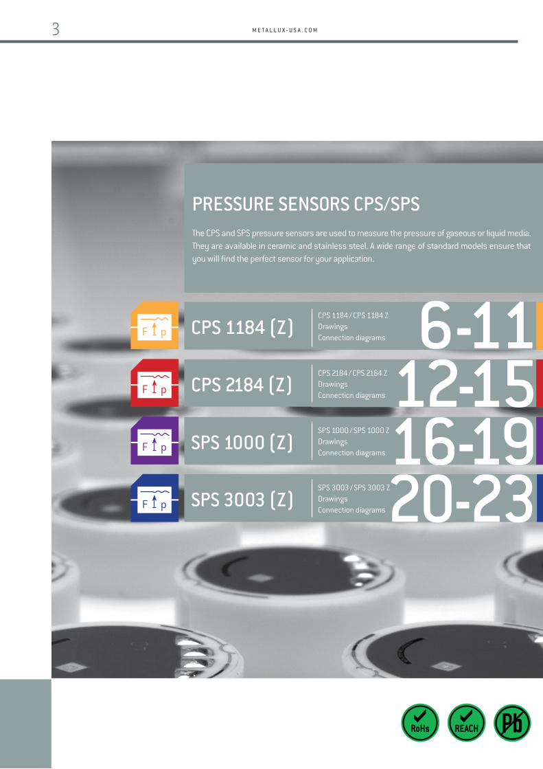
SPS 1000 (Z)
CPS 1184 (Z)
CPS 2184 (Z)
SPS 1000 / SPS 1000 ZDrawingsConnection diagrams
CPS 1184 / CPS 1184 ZDrawingsConnection diagrams
CPS 2184 / CPS 2184 ZDrawingsConnection diagrams
SPS 3003 (Z)SPS 3003 / SPS 3003 ZDrawingsConnection diagrams
12-1516-19
6-11
20-23
PRESSURE SENSORS CPS/SPSThe CPS and SPS pressure sensors are used to measure the pressure of gaseous or liquid media. They are available in ceramic and stainless steel. A wide range of standard models ensure that you will find the perfect sensor for your application.
3

P R E S S U R E S E N S O R S
OVERVIEW
VERSION CPS SPS
Page Pages 6 – 15 Pages 16 – 23
MATERIALS
Al2O3 x
Stainless steel x
SPECIAL FEATURES
Stability <0.1 % / <0.25 % (150° 1000 h) x
Standard temperature range −40 ... 85 °C x x
Very high burst pressure rating x
Integrated pressure connection x
Output 0.5 ... 4.5 V x x
APPLICATIONS
Hydraulics x
Pneumatics x
Pressure transmitters x x
Pressure switches x x
Pumps x x
Filters x
High-pressure cleaners x x
APPLICATIONS
Hydraulics Pneumatics Pressure transmitters Pressure switches
Pumps Force transmitters Filters High-pressure cleaners
Safe, long-term operation in your device. The ceramic and steel materials have been selected to ensure a long service life in most media.
Choose from a comprehensive range of sensors. Our wide selection of sensors ensures that you will find the right sensor for your application.
You can rely on chemical resistant sensors. The materials have been selected for highly safe, reliable operation.
Easy assembly so that your production process is seamless.
PRESSURE SENSORS FROM METALLUX
© w
ww
.met
allu
x-us
a.co
m 0
1/20
17
4

M E T A L L U X - U S A . C O M
PRESSURE TRANSMITTERS / PRESSURE SWITCHES
Ceramic pressure sensors in thick-film technology reliably record pressures in pressure transmitters and pressure switches. These highly precise and affordable sensors monitor process parameters in production processes ensuring the quality of the manufactured products.
AUTOMOTIVE APPLICATIONS
Ceramic monolithic pressure sensors perform various tasks in automotive applications. They are used to monitor filter pressure, oil and fuel pressure and monitor the pneumatic and hydraulic brake fluid circuits incommercial and private vehicles. High reliability, precision and highly resistant against aggressive media,make this technology suitable for an ever growing range of applications.
HYDRAULICS/REFRIGERATION EQUIPMENT
An extremely high burst pressure rating and high reliability make this SPS stainless steel sensor an attractive alternative. The monolith with screw connection eliminates the need for a seal between the sensor and the pressure connection. This also eliminates the risk of mechanical weak points, such as welding joints. With this model, it is possible to achieve even higher resistance to aggressive media.
MEDICAL TECHNOLOGY
Some patients depend on dialysis equipment for their survival. There is zero room for error when it comes tothe precision pressure sensors that monitor the system pressure. The manufacturers of dialysis systems puttheir trust in Metallux pressure sensors. For self-cleaning dialysis equipment, the high chemical compatibilityand front-flush diaphragm on the sensors are particularly attractive features.
Perfect measuring cells for your applications
PRESSURE MEASURING CELLS WITH THICK-FILM TECHNOLOGY ON A CERAMIC OR STAINLESS STEEL BASE
© www.metallux-usa.com 01/2017
5

P R E S S U R E S E N S O R S
Metallux monolithic pressure sensors are manufactured in large series and are in use in a range of applications in machinery production, the automotive industry, and ventilation and climate control equipment. The easy installation and calibration of the sensors simplifies the customer's production processes. The CPS 1184 features a compact design, high media compatibility and excellent long-term stability.
SAMPLE ORDER
Type Pressure range (bar) Electrical connection (acc. to drawing)
CPS 1184 100 bar Solder pads
Other dimensions and electrical specifications on request.
PRESSURE RANGE(BAR)
LONG THERM STABILITY (% FS) *
LINEARITY / HYSTERESIS(TYP./MAX.) (% FS) **
BURST PRESSURE(BAR)
OVER-PRESSURE(BAR) ***
VACUUM CAPABILITY(BAR)
2 (1.6 ... 2.5) ± 0.15 ± 0.15 / 0.4 ≥ 5 ≤ 3 −0.6
5 (4 ... 6) ± 0.15 ± 0.15 / 0.4 ≥ 15 ≤ 7,5 −0.8
10 ± 0.1 ± 0.15 / 0.4 ≥ 30 ≤ 15 −1
20 (16 ... 25) ± 0.1 ± 0.15 / 0.4 ≥ 60 ≤ 30 −1
50 (40 ... 60) ± 0.1 ± 0.15 / 0.4 ≥ 150 ≤ 75 −1
100 ± 0.1 ± 0.2 / 0.5 ≥ 250 ≤ 150 −1
200 (160 ... 250) ± 0.1 ± 0.2 / 0.5 ≥ 450 ≤ 300 −1
400 ± 0.15 ± 0.3 / 0.6 ≥ 700 ≤ 550 −1
600 ± 0.15 ± 0.3 / 0.6 ≥ 900 ≤ 720 −1
Mechanical and electrical characteristics are customisable. Specifications are subject to change without notice. We recommend that customers perform their own tests for new or untested applications.
TECHNICAL SPECIFICATIONS
Supply voltage 4 ... 30 VDC
Impedance 10 kOhm ± 20 %
FS output (Span) Min. 1.5 / typ. 2.8 / max. 5.3 mV/V
Offset 0 ± 0.2 mV/V
Therm. offset shift Typ. 0 ± 0.015 / max. 0 ± 0.02 % FS/K (25 ... 85 °C)
Therm. span shift0 ... −0.013 % FS/K (0 ... 70 °C)0 ... −0.015 % FS/K (−20 ... 0 °C / 70 ... 85 °C)0 ... −0.018 % FS/K (−40 ... 0 °C / 85 ... 135 °C)
Insulating resistor >1Gohm @ 500 VDC, RT, 70 % rH (clamping 16.00mm)
Insulating voltage> 0.5 kVDC with minimal membrane thickness, from medium to printed circuit
Body material Al2O
3 96 %
Operating temperature −40 ... +150 °C
Storage temperature −40 ... +150 °C
* 1000 hours @ 150 °C | 50 million pressure cycles @ 125 °C, 10 – 90 % FS @ 2.5 Hz | 3 thermal shocks +130 °C /−20 °C 3 K/sec. | 50 thermal cycles +150 °C /−40 °C, 2 K/min.** For indipendent linearity 10 points are measured and compared to an ideal straight line. | For all measurements, DUT’s are mounted in Metallux standard Housing according to "mounting proposal CPS 1184".*** Over-Pressure indicates the maximum (short time < 1 s) operating pressure within no irreversible damage to the printed circuit are expected.
CERAMIC STANDARD PRESSURE SENSOR CPS 1184 RM 2.54
© www.metallux-usa.com 01/2018
6

M E T A L L U X - U S A . C O M
DIMENSIONAL DRAWINGS / CONNECTOR SCHEMATIC / ELECTRICAL CONNECTORS
Standard:Tin plated: Sn95.6; Ag3.8; Cu0.6
Type of connection:flat cable
Type of connection:Pins 0.5 x 0.27mm
Ø 18.00±0.10
RZ max. 6
0.05
0.02
CUnprinted surfaces
6.35
± 0
.05 Ø 14.50±0.2
Printed area
Solder Pads: Ag/Pd 20:1
Pressurerange label
Clamping area
> Ø 15.5 mm15° ± 2°
max. Ø 15.90min. Ø 11.00
Sealing Area
Ø 9.70
4 x R 0.75
Tin
heig
ht0.
2 ±
0.1
5.55
1.50
7.622.541.50 +Ub S− S+− Ub
+Ub
S− S+
− Ub
10 K10 K
10 K10 K
Ly
Lx
Coating
1.5+0.5pre-tinned
Wx
max
. 15
Hx
10°+20°
2 ±
0.5
Specific connectors on request m
ax. 2
.0
5.53 ± 0.20
2.54
Varia
ble
leng
thm
ax. 1
3 m
mm
in. 6
mm
± 0
.3 m
m
metallux-usa.com Indent. No.
© www.metallux-usa.com 01/2018
7

P R E S S U R E S E N S O R S
Metallux monolithic pressure sensors are manufactured in large series and are in use in a range of applications in machinery production, the automotive industry, and ventilation and climate control equipment. The easy installation and calibration of the sensors simplifies the customer's production processes. The CPS 1184 features a compact design, high media compatibility and excellent long-term stability.
SAMPLE ORDER
Type Pressure range (bar) Electrical connection (acc. to drawing)
CPS 1184 100 bar Solder pads
Other dimensions and electrical specifications on request.
© www.metallux-usa.com 01/2018
PRESSURE RANGE(BAR)
LONG THERM STABILITY *
LINEARITY / HYSTERESIS(TYP./MAX.) (% FS) **
BURST PRESSURE(BAR)
OVER-PRESSURE(BAR) ***
VACUUM CAPABILITY(BAR)
2 (1.6 ... 2.5) ± 0.15 ± 0.15 / 0.4 ≥ 5 ≤ 3 −0.6
5 (4 ... 6) ± 0.15 ± 0.15 / 0.4 ≥ 15 ≤ 7,5 −0.8
10 ± 0.1 ± 0.15 / 0.4 ≥ 30 ≤ 15 −1
20 (16 ... 25) ± 0.1 ± 0.15 / 0.4 ≥ 60 ≤ 30 −1
50 (40 ... 60) ± 0.1 ± 0.15 / 0.4 ≥ 150 ≤ 75 −1
100 ± 0.1 ± 0.2 / 0.5 ≥ 250 ≤ 150 −1
200 (160 ... 250) ± 0.1 ± 0.2 / 0.5 ≥ 450 ≤ 300 −1
400 ± 0.15 ± 0.3 / 0.6 ≥ 700 ≤ 550 −1
600 ± 0.15 ± 0.3 / 0.6 ≥ 900 ≤ 720 −1
TECHNICAL SPECIFICATIONS
Supply voltage 4 ... 30 VDC
Impedance 10 kOhm ± 20 %
FS output (Span) Min. 1.5 / typ. 2.8 / max. 5.3 mV/V
Offset 0 ± 0.2 mV/V
Therm. offset shift Typ. 0 ± 0.015 / max. 0 ± 0.02 % FS/K (25 ... 85 °C)
Therm. span shift0 ... −0.013 % FS/K (0 ... 70 °C)0 ... −0.015 % FS/K (−20 ... 0 °C / 70 ... 85 °C)0 ... −0.018 % FS/K (−40 ... 0 °C / 85 ... 135 °C)
Insulating resistor >1Gohm @ 500 VDC, RT, 70 % rH (clamping 16.00mm)
Insulating voltage> 0.5 kVDC with minimal membrane thickness, from medium to printed circuit
Body material Al2O
3 96 %
Operating temperature −40 ... +150 °C
Storage temperature −40 ... +150 °C
Mechanical and electrical characteristics are customisable. Specifications are subject to change without notice. We recommend that customers perform their own tests for new or untested applications.
CERAMIC STANDARD PRESSURE SENSOR CPS 1184 RM 1.27
* 1000 hours @ 150 °C | 50 million pressure cycles @ 125 °C, 10 – 90 % FS @ 2.5 Hz | 3 thermal shocks +130 °C /−20 °C 3 K/sec. | 50 thermal cycles +150 °C /−40 °C, 2 K/min.** For indipendent linearity 10 points are measured and compared to an ideal straight line. | For all measurements, DUT’s are mounted in Metallux standard Housing according to "mounting proposal CPS 1184".*** Over-Pressure indicates the maximum (short time < 1 s) operating pressure within no irreversible damage to the printed circuit are expected.
8

M E T A L L U X - U S A . C O M
DIMENSIONAL DRAWINGS / CONNECTOR SCHEMATIC / ELECTRICAL CONNECTORS
Standard:Tin plated: Sn95.6; Ag3.8; Cu0.6
Type of connection:flat cable
Ø 18.00±0.10
RZ max. 6
0.05
0.02
C
Ø 9.30
6.35
± 0
.05
Ø 14.50±0.2
Printed area
Solder pads: Ag/Pd
metallux-usa.com Indent. No.
15° ± 2°
6.85
3.81
4.72 1.27
0.80+Ub S− S+− Ub
+Ub
S− S+
− Ub
10 K10 K
10 K10 K
max. Ø 15.90min. Ø 11.00
Sealing Area
Ø 9.70
4 x R 0.75
Ly
Lx
Coating
1.5+0.5pre-tinned
Wx
max
. 8
Hx10°+20°
2 ±
0.5
Specific connectors on requestTi
n he
ight
0.2
±0.
1
Unprinted surfaces
Clamping area
> Ø 15.5 mm
Pressure range
© www.metallux-usa.com 01/2018
9

P R E S S U R E S E N S O R S
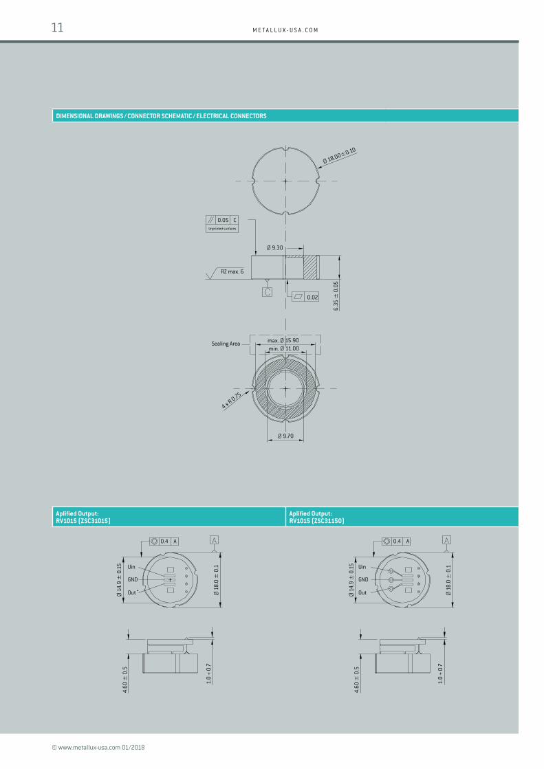
The ceramic pressure sensors in the CPS 1184 Z series are integrated with an amplifier and are supplied calibrated to an output signal of 0.5 V to 4.5 V.
The excellent long-term stability and high resistance against a wide range of media are additional features of this sensor series.
SAMPLE ORDER
Type Pressure range (bar) Electrical connection (acc. to drawing)
CPS 1184 Z 100 bar Solder pads
Other dimensions and electrical specifications on request.
PRESSURE RANGE(BAR)
LONG THERM STABILITY *
LINEARITY / HYSTERESIS(TYP./MAX.) (% FS) **
BURST PRESSURE(BAR)
OVER-PRESSURE(BAR) ***
VACUUM CAPABILITY(BAR)
2 (1.6 ... 2.5) ± 0.25 ± 0.15 / 0.4 ≥ 5 ≤ 3 −0.6
5 (4 ... 6) ± 0.25 ± 0.15 / 0.4 ≥ 15 ≤ 7,5 −0.8
10 ± 0.15 ± 0.15 / 0.4 ≥ 30 ≤ 15 −1
20 (16 ... 25) ± 0.15 ± 0.15 / 0.4 ≥ 60 ≤ 30 −1
50 (40 ... 60) ± 0.15 ± 0.15 / 0.4 ≥ 150 ≤ 75 −1
100 ± 0.2 ± 0.2 / 0.5 ≥ 250 ≤ 150 −1
200 (160 ... 250) ± 0.2 ± 0.2 / 0.5 ≥ 450 ≤ 300 −1
400 ± 0.25 ± 0.3 / 0.6 ≥ 700 ≤ 550 −1
600 ± 0.25 ± 0.3 / 0.6 ≥ 900 ≤ 720 −1
* 1000 hours @ 125 °C | 50 million pressure cycles @ 25 °C, 10 – 90 % FS @ 2.5 Hz | 50 thermal cycles +125 °C/−40 °C, 2 K/min.** For indipendent linearity 10 points are measured and compared to an ideal straight line. | For all measurements, DUT’s are mounted in Metallux standard Housing according to "mounting proposal CPS 1184".*** Over-Pressure indicates the maximum (short time < 1 s) operating pressure within no irreversible damage to the printed circuit are expected.
TECHNICAL SPECIFICATIONS
Supply voltage 5 V ± 0.5 VDC
Power consumption < 10 mA typ. Rload > 2 k) < 50 mA max.
Output signal 0.5 ... 4.5 V ratiometric
Kalibrierfehler ± 1 % / FS
Therm. offset shift 0 ± 0.05 % FS/K (0 ... 80 °C not compensated)
Therm. span shift 0 ... −0.012 % FS/K (20 ... 80 °C)0 ... −0.018 % FS/K (−40 ... 125 °C)
Sample rate 1 kHz typ. / 0.5 kHz min.
Insulating resistor >1Gohm @ 500 VDC, RT, 70 % rH (clamping 16.00mm)
Insulating voltage> 0.5 kVDC with minimal membrane thickness, from medium to printed circuit
Body material Ceramic AL203 96 %
Operating temperature −40 ... +125 °C
Storage temperature −20 ... +125 °C
Mechanical and electrical characteristics are customisable. Specifications are subject to change without notice. We recommend that customers perform their own tests for new or untested applications.
CERAMIC STANDARD PRESSURE SENSOR CPS 1184 Zwith output amplifier
© www.metallux-usa.com 01/2018
10
M E T A L L U X - U S A . C O M
DIMENSIONAL DRAWINGS / CONNECTOR SCHEMATIC / ELECTRICAL CONNECTORS
Aplified Output: RV1015 (ZSC31015)
Aplified Output: RV1015 (ZSC31150)
Ø 18.00±0.10
RZ max. 6
0.05
0.02
C
Ø 9.30
6.35
± 0
.05
max. Ø 15.90min. Ø 11.00
Sealing Area
Ø 9.70
4 x R 0.75
0.4 A
Ø 1
4.9
± 0
.15
Ø 1
8.0
± 0
.1Uin
GND
Out
4.60
± 0
.5
1.0
+ 0.
7
0.4 A
Ø 1
4.9
± 0
.15
Ø 1
8.0
± 0
.1Uin
GND
Out
4.60
± 0
.5
1.0
+ 0.
7
Unprinted surfaces
© www.metallux-usa.com 01/2018
11

P R E S S U R E S E N S O R S
The CPS 2184 sensors with front-flush diaphragm seal are suitable for measurement of relative as well as absolute pressures. The flush-front diaphragm makes for easy cleaning, an important requirement for sensors used in the medical and food industry.
The sensors are also available with diaphragms with 99.6 % aluminium oxide, for applications with extremely aggressive media.
SAMPLE ORDER
Type Pressure range (bar) Pressure type Electrical connection (acc. to drawing)
CPS 2184 100 bar A/R/SG Solder pads
Other dimensions and electrical specifications on request.
PRESSURE RANGE(BAR)
LONG THERM STABILITY *
LINEARITY / HYSTERESIS(TYP./MAX.) (% FS) **
BURST PRESSURE(BAR)
OVER-PRESSURE(BAR) ***
VACUUM CAPABILITY(BAR)
TYPE
0.5 ± 0.25 ± 0.3 / 0.6 ≥ 1,5 ≤ 1 −0.1 Rel.
1 ± 0.25 ± 0.25 / 0.6 ≥ 2,5 ≤ 1,5 −0.4 Rel. / Abs.
2 ± 0.2 ± 0.2 / 0.5 ≥ 5 ≤ 3 −0.6 Rel. / Abs.
5 ± 0.2 ± 0.2 / 0.5 ≥ 12 ≤ 7,5 −1 Rel. / Abs.
10 ± 0.2 ± 0.2 / 0.4 ≥ 25 ≤ 15 −1 Rel. / Abs.
20 ± 0.15 ± 0.2 / 0.4 ≥ 40 ≤ 30 −1 Rel. / Abs.
50 ± 0.2 ± 0.2 / 0.4 ≥ 100 ≤ 75 −1 Rel. / Abs.
100 ± 0.25 ± 0.25 / 0.5 ≥ 250 ≤ 150 −1 Sealed gauge
200 ± 0.25 ± 0.25 / 0.6 ≥ 400 ≤ 300 −1 Sealed gauge
400 ± 0.25 ± 0.25 / 0.6 ≥ 600 ≤ 500 −1 Sealed gauge
600 ± 0.25 ± 0.3 / 0.6 ≥ 700 ≤ 700 −1 Sealed gauge
TECHNICAL SPECIFICATIONS
Supply voltage 4 ... 30 VDC
Impedance 10 kOhm ± 20 %
FS output (Span) Min. 1.5 / typ. 3.2 / max. 6 mV/V
Offset 0 ± 0.2 mV/V
Therm. offset shift Typ. 0 ± 0.015 / max. 0 ± 0.03 % FS/K (25 ... 85 °C)
Therm. span shift0 ... −0.013 % FS/K (0 ... 70 °C)0 ... −0.015 % FS/K (−20 ... 0 °C / 70 ... 85 °C)0 ... −0.018 % FS/K (−40 ... 0 °C / 85 ... 135 °C)
Insulating resistor >1 Gohm @ 500 VDC, RT, 70 % rH (mounting 16.00mm)
Insulating voltage> 0.5 kVDC with minimal membrane thickness, from medium to printed circuit
Body material Al2O
3 96 %
Operating temperature −40 ... +135 °C
Storage temperature −40 ... +150 °C
* 1000 hours @ 150 °C | 50 million pressure cycles @ 80 °C, 10 – 90 % FS @ 2.5 Hz | 3 thermal shocks +125 °C/−20 °C, 3 K/sec | 50 thermal cycles +135 °C/−40 °C, 2 K/min.** For indipendent linearity 10 points are measured and compared to an ideal straight line. | For all measurements, DUT’s are mounted in Metallux standard Housing according to "mounting proposa CPS 2184-ND-HD".*** Over-Pressure indicates the maximum (short time < 1 s) operating pressure within no irreversible damage to the printed circuit are expected.
Mechanical and electrical characteristics are customisable. Specifications are subject to change without notice. We recommend that customers perform their own tests for new or untested applications.
CERAMIC STANDARD PRESSURE SENSOR CPS 2184
© www.metallux-usa.com 01/2017
12

M E T A L L U X - U S A . C O M
DIMENSIONAL DRAWINGS / CONNECTOR SCHEMATIC / ELECTRICAL CONNECTORS
2.93
1.78
1.782.545.08
1.35
± 0
.35
Clamping Solder ball (only for absolute version)
Heig
ht X
Rz max. 6
Ø 18.00±0.10
R 0.75B
S+V–Ref Lo+ S− Lo−
Lo+Lo−
10 K10 K
10 K10 K
S− S+
V–Ref
max. Ø 15.90min. Ø 12.00
Sealing AreaRound membrane
Ø 9.40
2 x R 0.75
Ø 1
8.00
Mem
bran
e
0.25 BSensor area
Tin
heig
ht0.
2 ±
0.1
max
. 2.0
Varia
ble
leng
thm
ax. 1
3 m
mm
in. 6
mm
± 0
.3 m
m
2.90 ± 0.30
Solder pads: Ag/Pd 20:1
30° ± 2°
Ø 14.50±0.2
Printed area
Clamping area
> Ø 15.5 mm
Pressure range
Ø 6.800.25 B
Sensor area
max. Ø 15.90min. Ø 9.40
Sealing AreaOctagonal membrane
Ø 1
6.54
± 0
.10
Mem
bran
e
4 x R 0.75
TABLE FOR HEIGHT X ROUND (MM)
0 – 0.5 bar 6.13 ± 0.15
0 – 1 bar 6.20 ± 0.15
0 – 2 bar 6.25 ± 0.15
0 – 5 bar 6.30 ± 0.15
0 – 10 bar 6.35 ± 0.15
0 – 20 bar 6.55 ± 0.15
0 – 50 bar 6.70 ± 0.15
TABLE FOR HEIGHT X OCTAGONAL (MM)
0 – 100 bar 6.70 ± 0.15
0 – 200 bar 7.05 ± 0.15
0 – 400 bar 7.35 ± 0.2
0 – 600 bar 7.55 ± 0.2
Ly
Lx
1.5+0.5pre-tinned
Hx
Coating
Wx
max
. 15
10°+20°
2 ±
1
Specific connectors on request
Standard:Tin plated: Sn95.6; Ag3.8; Cu0.6
Type of connection:flat cable
Type of connection:Pins 0.5 x 0.27mm
metallux-usa.com Indent. No.
© www.metallux-usa.com 01/2017
13

P R E S S U R E S E N S O R S
Customers in the food, pharmaceutical and chemical industry rely on the flush mounted sensors of the series CPS 2184Z with integrated amplifier. The sensors are calibrated to an output signal of 0.5V to 4.5V.
Characteristic for this series is an excellent long term stability and its suitability to operate in a harsh environment.
SAMPLE ORDER
Type Pressure range (bar) Pressure type Electrical connection (acc. to drawing)
CPS 2184 Z 100 bar A/R/SG Solder pads
Other dimensions and electrical specifications on request.
PRESSURE RANGE(BAR)
LONG THERM STABILITY *
LINEARITY / HYSTERESIS(TYP./MAX.) (% FS) **
BURST PRESSURE(BAR)
OVER-PRESSURE(BAR) ***
VACUUM CAPABILITY(BAR)
TYPE
0.5 ± 0.3 ± 0.3 / 0.6 ≥ 1.5 ≤ 1 −0.1 Rel.
1 ± 0.3 ± 0.25 / 0.6 ≥ 2.5 ≤ 1.5 −0.4 Rel. / Abs.
2 ± 0.25 ± 0.2 / 0.5 ≥ 5 ≤ 3 −0.6 Rel. / Abs.
5 ± 0.25 ± 0.2 / 0.5 ≥ 12 ≤ 7.5 −1 Rel. / Abs.
10 ± 0.25 ± 0.2 / 0.4 ≥ 25 ≤ 15 −1 Rel. / Abs.
20 ± 0.2 ± 0.2 / 0.4 ≥ 40 ≤ 30 −1 Rel. / Abs.
50 ± 0.2 ± 0.2 / 0.4 ≥ 100 ≤ 75 −1 Rel. / Abs.
100 ± 0.3 ± 0.25 / 0.5 ≥ 250 ≤ 150 −1 Sealed gauge
200 ± 0.3 ± 0.25 / 0.6 ≥ 400 ≤ 300 −1 Sealed gauge
400 ± 0.3 ± 0.25 / 0.6 ≥ 600 ≤ 500 −1 Sealed gauge
600 ± 0.3 ± 0.3 / 0.6 ≥ 700 ≤ 700 −1 Sealed gauge
TECHNICAL SPECIFICATIONS
Supply voltage 5 V ± 0.5 VDC
Power consumption < 10 mA typ. Rload > 2 k) < 50 mA max.
Output signal 0.5 ... 4.5 V ratiometric
Kalibrierfehler ± 1 % / FS
Therm. offset shift 0 ± 0.05 % FS/K (0 ... 80 °C not compensated)
Therm. span shift 0 ... −0.012 % FS/K (20 ... 80 °C)0 ... −0.018 % FS/K (−40 ... 125 °C)
Sample rate 1 kHz typ. / 0.5 kHz min.
Insulating resistor 1 Gohm Q (with clamping Ø 16 mm)
Insulating voltage> 0.5 kVDC with minimal membrane thickness, from medium to printed circuit
Body material Ceramic AL203 96 %
Operating temperature −40 ... +125 °C
Storage temperature −20 ... +125 °C
* 1000 hours @ 125 °C | 50 million pressure cycles @ 25 °C, 10 – 90 % FS @ 2.5 Hz | 50 thermal cycles +125 °C/−40 °C, 2K/min.** For indipendent linearity 10 points are measured and compared to an ideal straight line. | For all measurements, DUT’s are mounted in Metallux standard Housing according to "mounting proposal CPS 2184-ND-HD".*** Over-Pressure indicates the maximum (short time < 1 s) operating pressure within no irreversible damage to the printed circuit ar expected.
Mechanical and electrical characteristics are customisable. Specifications are subject to change without notice. We recommend that customers perform their own tests for new or untested applications.
CERAMIC STANDARD PRESSURE SENSOR CPS 2184 Zwith output amplifier
© www.metallux-usa.com 01/2017
14

M E T A L L U X - U S A . C O M
DIMENSIONAL DRAWINGS / CONNECTOR SCHEMATIC / ELECTRICAL CONNECTORS
max. Ø 15.90min. Ø 12.00Sealing Area
Ø 9.40
2 x R 0.75
Ø 1
8.00
Mem
bran
e
0.25 BSensor area
1.35
± 0
.35
Clamping Solder ball (only for absolute version)
Rz max. 6
Ø 18.00±0.10
R 0.75B
Aplified Output: RV2015 (ZSC31015)
Aplified Output: RV2150 (ZSC31150)
0.4 A
Ø 1
4.9
± 0
.15
Ø 1
8.0
± 0
.1Out
GND
Uin
4.60
± 0
.5
1.0
+ 0.
7
UinGNDOut
0.4 A
Ø 1
4± 0
.15
Ø 1
8.0
± 0
.1
4.60
± 1
1.0
+ 0.
7
Heig
ht X
TABLE FOR HEIGHT X ROUND (MM)
0 – 0.5 bar 6.13 ± 0.15
0 – 1 bar 6.20 ± 0.15
0 – 2 bar 6.25 ± 0.15
0 – 5 bar 6.30 ± 0.15
0 – 10 bar 6.35 ± 0.15
0 – 20 bar 6.55 ± 0.15
0 – 50 bar 6.70 ± 0.15
TABLE FOR HEIGHT X OCTAGONAL (MM)
0 – 100 bar 6.70 ± 0.15
0 – 200 bar 7.05 ± 0.15
0 – 400 bar 7.35 ± 0.2
0 – 600 bar 7.55 ± 0.2
Ø 6.800.25 B
Sensor area
max. Ø 15.90min. Ø 9.40
Sealing AreaOctagonal membrane
Ø 1
6.54
± 0
.10
mem
bran
e
4 x R 0.75
© www.metallux-usa.com 01/2017
15

P R E S S U R E S E N S O R S
The stainless steel pressure sensors of the SPS 1000 series excel particularly through good overload and burst pressure characteristics. Even in cases of pressure peaks, the monolithic pressure sensors offer outstanding safety features.
Operating in an aggressive media does not influence their superb performance.
SAMPLE ORDER
Type Pressure range (bar) Electrical connection (acc. to drawing)
SPS 1000 100 bar Solder pads
Other dimensions and electrical specifications on request.
PRESSURE RANGE(BAR)
LONG THERM STABILITY *
LINEARITY / HYSTERESIS(TYP./MAX.) (% FS) **
BURST PRESSURE(BAR) * Pnom
OVER-PRESSURE(BAR) ***
VACUUM CAPABILITY(BAR)
10 ± 0.4 ± 0.25 / 0.6 ≥ 10 ≤ 15 −1
25 ± 0.35 ± 0.25 / 0.6 ≥ 10 ≤ 35 −1
40 ± 0.35 ± 0.25 / 0.6 ≥ 10 ≤ 60 −1
100 ± 0.3 ± 0.2 / 0.5 ≥ 10 ≤ 150 −1
200 ± 0.3 ± 0.2 / 0.5 ≥ 10 ≤ 300 −1
300 ± 0.25 ± 0.2 / 0.5 ≥ 10 ≤ 450 −1
400 ± 0.25 ± 0.2 / 0.5 ≥ 10 ≤ 600 −1
600 ± 0.25 ± 0.3 / 0.5 ≥ 10 ≤ 900 −1
1000 ± 0.25 ± 0.3 / 0.5 ≥ 10 ≤ 1350 −1
TECHNICAL SPECIFICATIONS
Supply voltage 4 ... 30 VDC
Impedance 10 kOhm ± 30 %
FS output (Span) Min. 1.8 / typ. 2.5 / max. 3.5 mV/V
Offset 0 ± 0.5 mV/V
Therm. offset shift Typ. 0 ± 0.03 / max. 0 ± 0.05 % FS/K (25 ... 85 °C)
Therm. span shift Typ. 0 ... −0.02 % FS/K (0 ... 70 °C)max. 0 ... −0.05 % FS/K (0 ... 70 °C)
Insulating resistor >100 MOhm @ 500 VDC, RT, 70 % rH
Body material Stainless steel
Operating temperature −40 ... +125 °C
Storage temperature −40 ... +125 °C
* 1000 hours @ 125 °C | 50 million pressure cycles @ 125 °C, 10 – 90 % FS @ 2.5 Hz | 50 thermal cycles +125 °C /−20 °C, 2 K/min.** For indipendent linearity 10 points are measured and compared to an ideal straight line. | For all measurements, DUT’s are mounted in Metallux standard Housing according to "mounting proposal SPS 1000".*** Over-Pressure indicates the maximum (short time < 1 s) operating pressure within no irreversible damage to the printed circuit are expected.
Mechanical and electrical characteristics are customisable. Specifications are subject to change without notice.
STAINLESS STEEL STANDARD PRESSURE SENSOR SPS 1000
© www.metallux-usa.com 01/2017
16

M E T A L L U X - U S A . C O M
DIMENSIONAL DRAWINGS / CONNECTOR SCHEMATIC / ELECTRICAL CONNECTORS
Standard:Tin plated: Sn95.6; Ag3.8; Cu0.6
Customer specific,Flex: Lx/Ly/Wx/Hx, coating: blue
Type of connection:flat cable
Rz max. 6
Ø 18.00±0.10
0.05
0.02
CUnprinted surfaces
6.35
± 0
.05
+Ub
S− S+
− Ub
10 K10 K
10 K10 K
7.622.541.50
5.95
5.60
1.60
1.60
15°
Clamping area> Ø 16.50
Ø 15.50±0.2
Printed area
Pressure range
Solder pads: Ag/Pd
max. Ø 15.90min. Ø 11.00Sealing Area
2 x R 0.75Ø 9.70
+Ub S− S+− Ub
Tin
heig
ht0.
2 ±
0.1
Ly1.5+0.5
pre-tinned
Lx
Coating
Wx
max
. 15
Hx
Specific connectors on request
10°+20° 2 ±
1
4.83 ± 0.20
max
. 2.0
Varia
ble
leng
thm
ax. 1
3 m
mm
in. 6
mm
± 0
.3 m
m
metallux-usa.com Indent. No.
© www.metallux-usa.com 01/2017
17

P R E S S U R E S E N S O R S
Monolithic sensors in stainless steel provide high overload capacity and provide an output signal of 0.5V to 4.5V. The SPS 1000 Z amplifier makes it easy to further process the sensor signal.
As with the SPS 1000, an important feature of this sensor is its above average chemical resistance and an excellent long term stability.
SAMPLE ORDER
Type Pressure range (bar) Electrical connection (acc. to drawing)
SPS 1000 Z 100 bar Solder pads
Other dimensions and electrical specifications on request.
PRESSURE RANGE(BAR)
LONG THERM STABILITY *
LINEARITY / HYSTERESIS(TYP./MAX.) (% FS) **
BURST PRESSURE(BAR)
OVER-PRESSURE(BAR) ***
VACUUM CAPABILITY(BAR)
10 ± 0.6 ± 0.25 / 0.6 ≥ 10 ≤ 15 −1
25 ± 0.5 ± 0.25 / 0.6 ≥ 10 ≤ 35 −1
40 ± 0.5 ± 0.25 / 0.6 ≥ 10 ≤ 60 −1
100 ± 0.5 ± 0.2 / 0.5 ≥ 10 ≤ 150 −1
200 ± 0.5 ± 0.2 / 0.5 ≥ 10 ≤ 300 −1
300 ± 0.4 ± 0.2 / 0.5 ≥ 10 ≤ 450 −1
400 ± 0.4 ± 0.2 / 0.5 ≥ 10 ≤ 600 −1
600 ± 0.4 ± 0.3 / 0.5 ≥ 10 ≤ 900 −1
1000 ± 0.4 ± 0.3 / 0.5 ≥ 10 ≤ 1350 −1
TECHNICAL SPECIFICATIONS
Supply voltage 5 V± 0.5 VDC
Power consumption < 10 mA typ. Rload > 2 k) < 50 mA max.
Output signal 0.5 ... 4.5 V ratiometric
Kalibrierfehler ± 1 % / FS
Therm. offset shift 0 ± 0.08 % FS/K (0 ... 80 °C not compensated)
Therm. span shift 0 ... −0.05 % FS/K (20 ... 80 °C)
Sample rate 1 kHz typ. / 0.5 kHz min.
Insulating resistor >100 MOhm @ 500 VDC, RT, 70 % rH
Sample rate 1 kHz typ. / 0.5 kHz min.
Body material Stainless steel
Operating temperature −40 ... +125 °C
Storage temperature −40 ... +125 °C
Mechanical and electrical characteristics are customisable. Specifications are subject to change without notice.
STAINLESS STEEL STANDARD PRESSURE SENSOR SPS 1000 Z
* 1000 hours @ 125 °C | 50 million pressure cycles @ 25 °C, 10 – 90 % FS @ 2.5 Hz | 50 thermal cycles +125 °C /−40 °C, 2 K/min.** For indipendent linearity 10 points are measured and compared to an ideal straight line. | For all measurements, DUT’s are mounted in Metallux standard Housing according to "mounting proposal SPS 1000".*** Over-Pressure indicates the maximum (short time < 1 s) operating pressure within no irreversible damage to the printed circuit are expected.
with output amplifier
© www.metallux-usa.com 01/2017
18

M E T A L L U X - U S A . C O M
DIMENSIONAL DRAWINGS / CONNECTOR SCHEMATIC / ELECTRICAL CONNECTORS
Aplified Output: RV1015 (ZSC31015)
Aplified Output: RV1150 (ZSC31150)
Ø 18.00±0.10
Rz max. 6
0.05
0.02
CUnprinted surfaces
6.35
± 0
.05
max. Ø 15.90min. Ø 11.00Sealing Area
Ø 9.702 x R 0.75
1,0
+ 0.
7
Out
GND
Uin
Ø 1
4.9
± 0
.15
0.4 A
Ø 1
8.0
± 0
.1
4.60
± 0
.5
0.4 A
Ø 1
4.9
± 0
.15
Ø 1
8.0
± 0
.1Uin
GND
Out
4.60
± 0
.5
1.0
+ 0.
7
© www.metallux-usa.com 01/2017
19

P R E S S U R E S E N S O R S
The SPS 3003 series of stainless steel pressure sensors with integrated pressure connector provides reliable operation in applications with aggressive media. There is no need for a seal between the sensor measuring cell and pressure connection. The high overload capacity and very high burst pressure rating are additional advantages of this sensor. In the case of an error or undefined peaks in pressure, the medium remains in the system.
SAMPLE ORDER
Type Pressure range (bar) Electrical connection (acc. to drawing)
SPS 3003 100 bar Solder pads
Other dimensions and electrical specifications on request.
PRESSURE RANGE(BAR)
LONG THERM STABILITY *
LINEARITY / HYSTERESIS(TYP./MAX.) (% FS) **
BURST PRESSURE(BAR)
OVER-PRESSURE(BAR) ***
VACUUM CAPABILITY(BAR)
10 ± 0.4 ± 0.25 / 0.6 ≥ 10 ≤ 15 −1
25 ± 0.35 ± 0.25 / 0.6 ≥ 10 ≤ 35 −1
40 ± 0.35 ± 0.25 / 0.6 ≥ 10 ≤ 60 −1
100 ± 0.3 ± 0.2 / 0.5 ≥ 10 ≤ 150 −1
200 ± 0.3 ± 0.2 / 0.5 ≥ 10 ≤ 300 −1
300 ± 0.25 ± 0.2 / 0.5 ≥ 10 ≤ 450 −1
400 ± 0.25 ± 0.2 / 0.5 ≥ 10 ≤ 600 −1
600 ± 0.25 ± 0.3 / 0.5 ≥ 10 ≤ 900 −1
1000 ± 0.25 ± 0.3 / 0.5 ≥ 10 ≤ 1350 −1
TECHNICAL SPECIFICATIONS
Supply voltage 4 ... 30 VDC
Impedance 10 kOhm ± 30 %
FS output (Span) Min. 1.8 / typ. 2.5 / max. 3.5 mV/V
Offset 0 ± 0.5 mV/V
Therm. offset shift Typ. 0 ± 0.03 / max. 0 ± 0.05 % FS/K (25 ... 85 °C)
Therm. span shift Typ. 0 ... −0.02 % FS/K (0 ... 70 °C)max. 0 ... −0.05 % FS/K (0 ... 70 °C)
Insulating resistor >100 MOhm @ 500 VDC, RT, 70 % rH
Body material Stainless steel
Operating temperature −40 ... +125 °C
Storage temperature −40 ... +125 °C
* 1000 hours @ 125 °C | 50 million pressure cycles @ 125 °C, 10 – 90 % FS @ 2.5 Hz | 50 thermal cycles +125 °C / −20 °C, 2 K/min.** For indipendent linearity 10 points are measured and compared to an ideal straight line. | For all measurements, DUT’s are mounted in Metallux standard Housing according to "mounting proposal SPS 1000".*** Over-Pressure indicates the maximum(short time < 1 s) operating pressure within no irreversible damage to the printed circuit are expected.
Mechanical and electrical characteristics are customisable. Specifications are subject to change without notice.
STAINLESS STEEL STANDARD PRESSURE SENSOR SPS 3003
© www.metallux-usa.com 01/2017
20

M E T A L L U X - U S A . C O M
DIMENSIONAL DRAWINGS / CONNECTOR SCHEMATIC / ELECTRICAL CONNECTORS
S−+Ub −Ub S+
24.0
0
18.0
0 ±
0.1
17.0
0 −
0.1
HEX 22
7.622.541.90
5.6
2.0
Solder pads: Ag/Pd 20:1
Pressure range
S+
S−
+Ub
−Ub
10 K10 K
10 K10 K
24.0
03.
50
2.10
2.65
± 0
.30
Ø 9.0 −0.1
G 1/4" A
Ø 11.10Ø 16.65
12.0
0 ±
0.1
01.
25
1.05
Area A1
Sealing A
Sealing B
Standard:Tin plated: Sn95.6; Ag3.8; Cu0.6
Type of connection:flat cable
Type of connection:Pins 0.5 x 0.27mm
Tin
heig
ht0.
2 ±
0.1
Varia
ble
leng
thm
ax. 1
3 m
mm
in. 6
mm
± 0
.3 m
m
max
. 2.0
4.60 ± 0.20
2.54
Ly
Lx
Coating
1.5+0.5pre-tinned
Wx
max
. 15
HX
10°+20°
2 ±
0.5
Specific connectors on request
Mounting procedure:Sealing version A: O-ring: Ø 11.5 x 2.5 (NBR) Tightening torque < 34 Nm Foreseeable offset displacement when surface A1
lies on the receptor approx 1 ... 4 % FS.
Sealing Version B: O-ring: Ø 6 x 1.5 (NBR) Tightening torque < 20 Nm No offset displacement
metallux-usa.com Indent. No.
© www.metallux-usa.com 01/2017
21

The SPS 3003 Z series unites a stainless steel pressure sensor with an integrated pressure connection and an amplifier circuit. The 0.5V...4.5V output is proportional to the applied pressure. No seal is required between the sensor and pressure connection, which makes the sensor particularly resistant to aggressive media. Its high burst pressure rating also makes it ideal for hydraulic applications.
SAMPLE ORDER
Type Pressure range (bar) Electrical connection (acc. to drawing)
SPS 3003 Z 100 bar Solder pads
Other dimensions and electrical specifications on request.
P R E S S U R E S E N S O R S
PRESSURE RANGE(BAR)
LONG THERM STABILITY *
LINEARITY / HYSTERESIS(TYP./MAX.) (% FS) **
BURST PRESSURE(BAR)
OVER-PRESSURE(BAR) ***
VACUUM CAPABILITY(BAR)
10 ± 0.6 ± 0.25 / 0.6 ≥ 10 ≤ 15 −1
25 ± 0.5 ± 0.25 / 0.6 ≥ 10 ≤ 35 −1
40 ± 0.5 ± 0.25 / 0.6 ≥ 10 ≤ 60 −1
100 ± 0.5 ± 0.2 / 0.5 ≥ 10 ≤ 150 −1
200 ± 0.5 ± 0.2 / 0.5 ≥ 10 ≤ 300 −1
300 ± 0.4 ± 0.2 / 0.5 ≥ 10 ≤ 450 −1
400 ± 0.4 ± 0.2 / 0.5 ≥ 10 ≤ 600 −1
600 ± 0.4 ± 0.3 / 0.5 ≥ 10 ≤ 900 −1
1000 ± 0.4 ± 0.3 / 0.5 ≥ 10 ≤ 1350 −1
TECHNICAL SPECIFICATIONS
Supply voltage 5 V± 0.5 VDC
Power consumption < 10 mA typ. Rload > 2 k) < 50 mA max.
Output signal 0.5 ... 4.5 V ratiometric
Calibration error ± 1 % / FS
Therm. offset shift 0 ± 0.08 % FS/K (0 ... 80 °C not compensated)
Therm. span shift 0 ... −0.05 % FS/K (20 ... 80 °C)
Sample rate 1 kHz typ. / 0.5 kHz min.
Insulating resistor >100 MOhm @ 500 VDC, RT, 70 % rH
Body material Stainless steel
Operating temperature −40 ... +125 °C
Storage temperature −40 ... +125 °C
* 1000 hours @ 125 °C | 50 million pressure cycles @ 25 °C, 10 – 90 % FS @ 2.5 Hz | 50 thermal cycles +125 °C /−40 °C, 2 K/min.** For indipendent linearity 10 points are measured and compared to an ideal straight line. | For all measurements, DUT’s are mounted in Metallux standard Housing according to "mounting proposal SPS 1000".*** Over-Pressure indicates the maximum (short time < 1 s) operating pressure within no irreversible damage to the printed circuit are expected.
Mechanical and electrical characteristics are customisable. Specifications are subject to change without notice.
STAINLESS STEEL STANDARD PRESSURE SENSOR SPS 3003 Zwith output amplifier
© www.metallux-usa.com 01/2017
22

M E T A L L U X - U S A . C O M
DIMENSIONAL DRAWINGS / CONNECTOR SCHEMATIC / ELECTRICAL CONNECTORS
24.0
03.
50
2.10
2.65
± 0
.30
Ø 9.0 −0.1
G 1/4" A
Ø 11.10Ø 16.65
Ø 1
2.00
± 0
.10
1.25
1.05
Area A1
Sealing A
Sealing B
Ø 2
4.00
18.0
0 ±
0.1
17.0
0 −
0.1
HEX 22
Aplified Output: RV1015 (ZSC31015)
Aplified Output: RV1150 (ZSC31150)
0.40.4 AA
Ø 1
4.9
± 0
.15
Ø 1
7.0
± 0
.1Uin
GND
Out Ø 1
4.9
± 0
.15
Ø 1
7.0
± 0
.1Uin
GND
Out
4.60
± 0
.5
4.60
± 0
.5
1.0
+ 0.
7
1.0
+ 0.
7
Mounting procedure:Sealing version A: O-ring: Ø 11.5 x 2.5 (NBR) Tightening torque < 34 Nm Foreseeable offset displacement when surface A1
lies on the receptor approx 1 ... 4 % FS.
Sealing Version B: O-ring: Ø 6 x 1.5 (NBR) Tightening torque < 20 Nm No offset displacement
© www.metallux-usa.com 01/2017
23

www.metallux-usa.com
© w
ww
.met
allu
x-us
a.co
m 0
1/20
18
METALLUX USA, INC.
2340 Brighton Henrietta | Town Line Road, Suite 4Rochester, NY 14623 | USAPHONE: +1 (585)360 - 0054 | FAX: +1 (866)429 - 0360E-mail: [email protected]
REPRESENTED BY REICHENBACH INTERNATIONAL INC.
2080 Stonesgate StreetWestlake Village, CA 91361 | USAPHONE: +1 (805) 495-7003 | www.reichenbachintl.comE-mail: [email protected]