Pressure Reducing & De-superheating Stations - ARI...
4
We sell Savings We sell Savings Flawless control with a proven product... Pressure Reducing & De-superheating Stations We sell Savings
-
Upload
truongminh -
Category
Documents
-
view
226 -
download
4
Transcript of Pressure Reducing & De-superheating Stations - ARI...

We sell Savings
We sell Savings
Flawless control witha proven product...
PressureReducing &De-superheatingStations
We sell Savings

THE NEED FOR A PRS
WHY IS STEAM GENERATED AT HIGH PRESSURE?
Most modern boilers operate at high pressures, typically 10.5 to 217.5 kg/cm g. Pressure Reducing Stations or PRD stations are
an integral part of any steam system. They reduce the pressure and hence, the temperature of steam just before the process.
8Steam at high pressure (HP) has a relatively higher density, or low volume than at atmospheric pressure.This means that the higher the pressure, the smaller the bore of pipework required for distribution of a given mass of steam. Smaller bore means smaller, therefore cheaper steam equipment.
8The boiler size stays small as HP steam has low volume.
8HP steam is drier than LP steam.
8Smaller bore pipes have much lower heat losses.
8HP boilers have fewer reduced output / ‘carryover’ problems.
Therefore it is energy efficient to produce and distribute HP steam and reduce pressure upstream of any items of plant designed to operate at a lower pressure.
ECONOMIC BENEFITS OF PRESSURE REDUCTION?
1. LP steam has higher latent heat and can tend to reduce the amount of steam produced by the boiler, ie higher efficiencies.
2. All steam equipment have a MAWP - maximum allowable working pressure. A PRS is used so that safe working pressures are not exceeded downstream of the PRV.
3. Less flash steam is lost if the plant is operated on LP steam. Reduced pressure lowers the temperature of the downstream pipework and reduces radiation losses.
4. The temperature of saturated steam varies with the pressure, so this also provides a simple method of controlling temperature of steam going to a process.
5.For the same output, LP steam equipment may be larger, but is still cheaper as it follows a lower design specification.
6.Plants are normally built in stages. Starting with the HP stage, we flash HP condensate and use the LP flash steam in the LP stage. This saves energy. At times the flash steam being generated is not enough and a PRV is used to maintain continuity of supply in the LP system.
THE PHYSICS OF PRESSURE REDUCTION
Steam imparts heat to the process by condensing into water, thus giving off its latent heat. Thus, the work done by steam in a
).process is primarily done by latent heat (h gf
In the graph, follow the higher pressure line A’ – B' – C' – D' on the curve. The total energy in saturated steam at the higher pressure still remains h , but the h ’ increases and the h ’ gg f f
decreases.
Hence, lower the pressure of steam, the higher the latent heat content (h ) or the Enthalpy of Evaporation. This is why use fg
steam at lower pressures.
So, to conserve fuel, if the process demands a certain ∆T for efficient heat transfer, then we have to find out the lowest pressure that satisfies the temperature demand.
WHAT IS SUPERHEATED STEAM?
When more heat is added to saturated steam in the region B-C, its temperarure rises further to reflect the amount of heat added. Steam in the region C – D is called Superheated steam.
Thus, Superheated steam is steam that is at a temperature higher than its boiling point (or saturation temperature) at the given pressure. For example, saturated steam at a pressure of 32 bar g has a temperature of 238.5°C. If further heat is added to this, its temperature could be 300°C at a pressure of 32 barg.
ADVANTAGES OF SUPERHEATED STEAM
Superheated steam has more energy, higher specific volume and can be transmitted in smaller lines, as higher velocities are possible. Typically, it is used in steam turbines for power generation. Its higher energy means a more efficient turbine, and since it has no possibility of moisture, it protects against damage/ misbalancing of turbine blades from water (pitting).
When water is heated, its temperature rises (region A – B ). As its temperature reaches the boiling point, its phase changes to steam (region B – C), with no rise in temperature, and it boils at its saturation temperature. Here a large amount of heat is added with no rise in temperature, but a change in phase. This steam is called Saturated steam.
The Bell Curve to the left shows this, with each line representing a constant pressure. The total energy in saturated steam is the sum of the enthalpy of water and the enthalpy of evaporation.
h = h + h gg f f
Where:h = Total enthalpy / Total heat of sat steam (kJ/kg)g
h = Enthalpy of Water (Sensible heat) (kJ/kg)f
h = Enthalpy of Evaporation (Latent heat) (kJ/kg)g f
THE PHYSICS OF STEAM
C’B’
D’
A
Critical Point
Superheatregion
Te
mp
era
ture
enil diuqil detarutaS
Liquidregion
A
CB
Saturated va
po
ur lin
e
Lin
es
of
co
ns
tan
t p
res
su
re
h f Lower pressure, but more energy!!h g f
hg
h ’f h ’gfhsuper
D
Two-phaseregion
ARI Steamline Pressure Reducing &De-Superheating Stations
4Assures dry steam at the desired set pressure
4All components are CS or NI
4Steam is not in direct contact with diaphragm - enhances life
4High quality of all components ensures reliability
4Field proven with over 1000 installations
4Extended warranty options available
4Packaged system with IBR approval
4Also available for water, air and gas
4Increased diaphragm area opens a larger main valve, allows greater capacity per line size than an internally piloted valve. PRV sizes up to 150 NB can be offered using this design.
4Diaphragm operated externally piloted valves are more sensitive to pressure changes - typical accuracy of ±3%.
4Perfectly suited for a large range of simple applications where critical control is not paramount.
4No external power requirement.
4Frictionless plug stem sealed by SS bellows - Zero leaks.
4Plug is guided V-port by default, to handle high pressure drop
4A wide set-point range and easy adjustment.
4Low-maintenance, rugged construction with a simple design.
4Very good resolution for set pressure selection.
4No small ports which could get blocked - feedback line 15NB
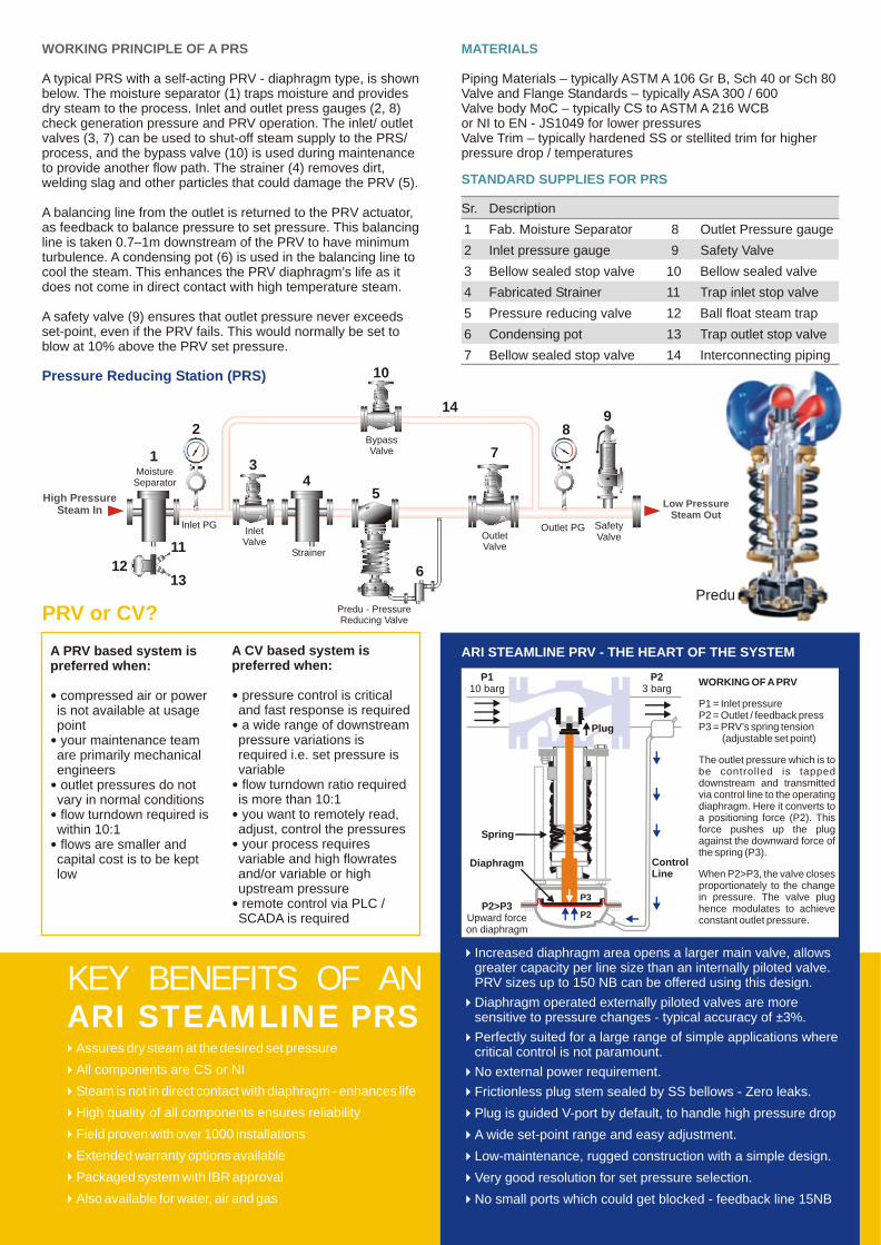
ARI STEAMLINE PRV - THE HEART OF THE SYSTEMA PRV based system is preferred when:
� compressed air or power is not available at usage point� your maintenance team are primarily mechanical engineers� outlet pressures do not vary in normal conditions� flow turndown required is within 10:1� flows are smaller and capital cost is to be kept low
A CV based system is preferred when:
� pressure control is critical and fast response is required� a wide range of downstream pressure variations is required i.e. set pressure is variable� flow turndown ratio required is more than 10:1� you want to remotely read, adjust, control the pressures� your process requires variable and high flowrates and/or variable or high upstream pressure� remote control via PLC / SCADA is required
STANDARD SUPPLIES FOR PRS
Sr. Description
1 Fab. Moisture Separator
2 Inlet pressure gauge
3 Bellow sealed stop valve
4 Fabricated Strainer
5 Pressure reducing valve
6 Condensing pot
7 Bellow sealed stop valve
8 Outlet Pressure gauge
9 Safety Valve
10 Bellow sealed valve
11 Trap inlet stop valve
14 Interconnecting piping
12 Ball float steam trap
13 Trap outlet stop valve
MATERIALS
Piping Materials – typically ASTM A 106 Gr B, Sch 40 or Sch 80Valve and Flange Standards – typically ASA 300 / 600 Valve body MoC – typically CS to ASTM A 216 WCB or NI to EN - JS1049 for lower pressuresValve Trim – typically hardened SS or stellited trim for higher pressure drop / temperatures
WORKING PRINCIPLE OF A PRS
A typical PRS with a self-acting PRV - diaphragm type, is shown below. The moisture separator (1) traps moisture and provides dry steam to the process. Inlet and outlet press gauges (2, 8) check generation pressure and PRV operation. The inlet/ outlet valves (3, 7) can be used to shut-off steam supply to the PRS/ process, and the bypass valve (10) is used during maintenance to provide another flow path. The strainer (4) removes dirt, welding slag and other particles that could damage the PRV (5).
A balancing line from the outlet is returned to the PRV actuator, as feedback to balance pressure to set pressure. This balancing line is taken 0.7–1m downstream of the PRV to have minimum turbulence. A condensing pot (6) is used in the balancing line to cool the steam. This enhances the PRV diaphragm’s life as it does not come in direct contact with high temperature steam.
A safety valve (9) ensures that outlet pressure never exceeds set-point, even if the PRV fails. This would normally be set to blow at 10% above the PRV set pressure.
Pressure Reducing Station (PRS)
KEY BENEFITS OF ANARI STEAMLINE PRS
PRV or CV?
WORKING OF A PRV
P1 = Inlet pressureP2 = Outlet / feedback pressP3 = PRV’s spring tension
(adjustable set point)
The outlet pressure which is to be controlled is tapped downstream and transmitted via control line to the operating diaphragm. Here it converts to a positioning force (P2). This force pushes up the plug against the downward force of the spring (P3).
When P2>P3, the valve closes proportionately to the change in pressure. The valve plug hence modulates to achieve constant outlet pressure.
P2
P110 barg
Plug
P2>P3Upward forceon diaphragm
P23 barg
Spring
ControlLine
Diaphragm
P3
OO
CC ZZ
AA
OO
CC ZZ
AA
OO
CC ZZ
AA
High Pressure Steam In
Low Pressure Steam Out
MoistureSeparator
1
2
Inlet PGInletValve
3
Strainer
4
Predu - PressureReducing Valve
5
OutletValve
7
14
BypassValve
10
Outlet PG SafetyValve
89
6
11
1213
Predu

4Assures steam at the desired set pressure and temp4Full alloy steel pressure reducing stage4Good turndown ratios on steam and water flow4Excellent control of pressure and temperature of steam due to
high accuracy of Sensors & Electronic PID Controllers4Designed specifically for critical applications with high pressure
ratios4Purpose designed industrial grade control valves, with stellited
trim where required, V-port or perforated plug options4Simple and rugged desuperheating, with no moving parts in
desuperheater4Easy integration with plant DCS or PLC Control Systems due to
open standards4High quality of all components ensures reliability4Field proven with over 160 installations4Extended warranty options available4Packaged system with IBR approval4Single vendor with complete package responsibility and
guarantee
WHAT IS A DESUPERHEATING STATION?
A Desuperheating station (DSH) 'de-superheats', in other words, cools superheated steam back to its saturated state.
Water is injected in a controlled manner, to take up extra heat, by evaporating into saturated steam. A temperature feedback is provided from the DSH outlet to a Control Valve in the Spray Water line, thus automatically varying the quantity of water as required. The Spray Water is atomised using one or more nozzles in the center of the steam path, to ensure complete mixing, and better evaporation of the water. This is done just after pressure reduction, when velocity is high and the flow is turbulent. The lance that holds the nozzle in the steam path, leads to further turbulence and better evaporation of the water.
A PRDSH combines two steam condition devices – a Pressure Reducing Valve and a Desuperheater. Typically, a PRDS will also have some steam conditioning like a strainer, isolation and bypass valves, a safety valve at the outlet, pressure and temperature monitoring, etc.
WHAT IS A PRDSH?
KEY BENEFITS OF AN
ARI STEAMLINE PRDSH
ChemicalsArcoy Biorefinery, Panoli (PRDSH) 1Benzo Chem Industries, Mumbai 1Clean Science & Tech P Ltd, Kurkumbh 1Croda Chemicals, Navi Mumbai 5Foods, Fats & Fertilisers, AP (PRDSH) 1Gujarat Insecticides, Ankleshwar 2Inventys Research Co P Ltd, Mumbai 1Jaimurthy Min, HP 1Jubilant Organosys, Mysore 1Lona Industries, Patalganga 5Multi Organics, Chandrapur 2Orchid Chemicals, Aurangabad 1Privi Aromatic, Mahad 6Shalina Laboratories, Mum (PRDSH) 2+4Shriram Trading & Mfg. Co., Kolhapur 2Thermax Chemicals, Khopoli 2UPL, Ankleshwar, Jhagadia, Vapi 7Vimal Organics, Ghaziabad 3Warna, Kolhapur 2
Vegetable OilsArian Engineering, Bhopal 5Cargill Foods India Ltd, Kurkumbh 2Dynamic Systems, Kolhapur 1Ruchi Soya, Indore / Patalganga 2 / 1Shivani Oil Mills, Kolhapur 2
PowerA2Z Powercom Pvt Ltd, Delhi 1
Food & BeverageCadbury India, Baddi / Pune 1 / 2Dugar Foods & Beverages, Nepal 2Dynamix Dairy, Pune 4Explicit Trading & Mktg, Ghaziabad 4Godrej Consumer Products, Pune 2Godrej Foods, MP 1Morya Distilleries, Paithan (PRDSH) 3Oaisis Alcohol Ltd., Satara (PRDSH) 3Padmesh Beverages, Guwahati 1Parag Milk Foods P Ltd, Pune 1Parakh Foods, Pune 7Parle Agro Mumbai (Fortune), Nasik 1Parle Agro, Bhopal/ Mandideep 3 / 3Parle Agro, Mumbai / Patalganga 2 / 1Parle Agro Frooti Beverages, Chennai 2Swastik Fruits Products, Ranchi 3Victoria Agro Food, Latur (PRDSH) 3
PharmaCadila Zydus, Ankleshwar 1Cipla, Patalganga 1Fresenius Kabi, Pune (PRDSH) 5+1Intervet, Pune 8IPCA Laboratories Ltd, Ratlam 1Kores India Limited, Roha 1Sajjan India Ltd, Ankleshwar 1Viva Drugs, Chandigarh 1Zydus, Mumbai 4
OEMsAtlas Copco (I) Ltd, Pune 2Cee Dee Vaccum, Pune 1Eclipse, Pune 1Filtron Engineers, Pune 7Jasubhai Engg Pvt Ltd, Mumbai 1KBK Chem Engg, Pune (PRDSH) 2+8Nestler Limited, Mumbai (PRDSH) 6+2Praj Industries Ltd, Pune (PRDSH) 5+5Praj R&D, Pune 2Precision Controls, Pune 3
AutoSuvarna Fibrotech, Pune 8Tata ACSI, Pune 48Tata ACSI, Uttaranchal 16
TextileAlok Industries, Vapi 16Arjuna Cotton, Pune 2Oswal Denims, Punjab 1Leela Dye House, Chandigarh 1Mtex Machines P Ltd, Navi Mumbai 1
OthersAmmunition Factory Khadki 16Brown Paper Tech, Pune 1Govind Rubber Ltd, Mumbai 2
Re
fere
nc
es
ARI Steamline Pressure Reducing &De-Superheating Stations
AR
I A
rma
ture
n S
tea
mlin
e L
LP
Allr
igh
ts r
ese
rve
d.
ARI Armaturen Steamline LLP TM • Survey No. 32/3/14, Kondhwa Budruk, Pune 411048 India
Phone: + 91 20 2693 2213 • Fax: + 91 20 2963 2214 • Email: [email protected] • Web: www.ari-steamline.com
ARI-Armaturen Albert Richter GmbH & Co. KG • Mergelheide 56-60 D-33758 Schloß Holte-Stukenbrock, Germany AR
I A
rma
ture
n S
tea
mlin
e L
LP
Allr
igh
ts r
ese
rve
d.
High Pressure Superheated
Steam In
Low Pressure SaturatedSteam Out
InletPressure
Strainer
InletValve
OutletValve
SteviControl Valve
BypassValve
OutletPressure
PressureController
PressureTransmitter
TemperatureController
Water
SteviControlValve
NRV
TempSensor
InletTemp
OutletTemp
ARI
OO
CC ZZ
AA
OO
CC ZZ
AA
OO
CC ZZ
AA
ARI
OO
CC ZZ
AAOO
CC ZZ
AA
SafetyValve