PRESSURE GAUGES - nidec-copal-electronics.com · 振 動 Vibration 10 ~ 500 Hz, 98.1 m/s2 or 1.5 mm...
8
広い分野で使用可能な、視認性に優れた小型圧力ゲージ 圧力ゲージ PG-35 PRESSURE GAUGES ● 連成圧・絶対圧タイプをラインアップ 1 台で負圧から正圧まで測定可能な連成圧タイプと絶対圧タイプを標準 化。 ● 小型・軽量防滴構造の汎用圧力ゲージ □ 30 mm の小型圧力ゲージで防滴構造(IP65)を実現。 ● 視認性に優れた LED の採用 パネル面取付は勿論、暗所でも見易い LED 表示。 ● 用途に応じた設定が可能 3つのアナログ出力モード 8種類のスイッチ出力モード ● EMC 規格 EN 55011 (EMI) EN 61326-1 (EMS) ● 非表示モードによる低消費電力 ● パネルロック機能による設定データの保護 ● Both absolute pressure type and compound pres- sure type are available Compound pressure type measures negative and positive gauge pressure. ● Compact and lightweight general-purpose pressure gauges Innovative general-purpose gauges of compact design (30mm sq.) and drip-proof structure (IP65). ● Clear indication by LED Easy-to-see LED assures clear readings on the panel and even in a dark place. ● Various modes and units can be selected according to applications Eight different pressure units Three analog output modes Eight switch output modes ● Meet EMC standards EN 55011 (EMI) EN 61326-1 (EMS) ● Low consumption by nondisplay mode ● Set data protection by panel lock function ■特 長 FEATURES 1 2 3 4 5 6 7 8 名 称 Part name 材 料 Material センサモジュール Sensor module アダプタ Adaptor FPC ケース Case パネルシート Panel sheet O リング “O” ring センサホルダ Sensor holder 継 手 Fitting 5 7 6 1 2 3 4 8 SUS316L SUS316L アルミニウム Aluminum ポリイミド Polymide PBT (Polybutyleneterphthalate) ポリエステル Polyester NBR SUS316L 内部構造図 INTERNAL STRUCTURE (R 1/4) マーキング EMC指令適合 marking Compatible with EMC directive
Transcript of PRESSURE GAUGES - nidec-copal-electronics.com · 振 動 Vibration 10 ~ 500 Hz, 98.1 m/s2 or 1.5 mm...

広い分野で使用可能な、視認性に優れた小型圧力ゲージ圧力ゲージ PG-35PRESSURE GAUGES
● 連成圧・絶対圧タイプをラインアップ1 台で負圧から正圧まで測定可能な連成圧タイプと絶対圧タイプを標準
化。
● 小型・軽量防滴構造の汎用圧力ゲージ□ 30 mm の小型圧力ゲージで防滴構造(IP65)を実現。
● 視認性に優れた LEDの採用パネル面取付は勿論、暗所でも見易い LED 表示。
● 用途に応じた設定が可能3つのアナログ出力モード
8種類のスイッチ出力モード
● EMC規格EN 55011 (EMI)
EN 61326-1 (EMS)
● 非表示モードによる低消費電力
● パネルロック機能による設定データの保護● Both absolute pressure type and compound pres
sure type are availableCompound pressure type measures negative and positive gauge pressure.
● Compact and lightweight generalpurpose pressure gaugesInnovative general-purpose gauges of compact design (30mm sq.) and drip-proof structure (IP65).
● Clear indication by LEDEasy-to-see LED assures clear readings on the panel and even in a dark place.
● Various modes and units can be selected according to applicationsEight different pressure unitsThree analog output modesEight switch output modes
● Meet EMC standardsEN 55011 (EMI)EN 61326-1 (EMS)
● Low consumption by nondisplay mode
● Set data protection by panel lock function
■特 長 FEATURES 1
2
3
4
5
6
7
8
名 称Part name
材 料Material
センサモジュールSensor moduleアダプタAdaptor
FPC
ケースCaseパネルシートPanel sheetOリング“O” ringセンサホルダSensor holder
継 手Fitting
5
7
6
1
2
3
4
8
SUS316L
SUS316L
アルミニウムAluminumポリイミドPolymide
PBT (Polybutyleneterphthalate)
ポリエステルPolyester
NBR
SUS316L
内部構造図INTERNAL STRUCTURE(R 1/4)
マーキングEMC指令適合
markingCompatible withEMC directive

PG-35PRESSURE GAUGES
■型式表示 MODEL NUMBER DESIGNATIONP G - 3 5 - 1 0 2 R - N R 2 B
型式名 Series name
圧力レンジ Pressure range102R:− 100 ~ 100 kPa(連成圧 Compound pressure [Negative pressure ~ Positive pressure])102A: 0 ~ 100 kPa(絶対圧 Absolute pressure [Absolute vacuum ~ Barometic pressure])103R:− 100 ~ 1000 kPa(連成圧 Compound pressure [Negative pressure ~ Positive pressure])
指示方法 Pressure referenceR:連成圧(負圧〜正圧)Compound pressure (Negative pressure ~ Positive pressure)A:絶対圧(絶対真空〜大気圧)Absolute pressure (Absolute vacuum ~ Barometic pressure)
継手形状 FittingR2:R 1/4(M 5 メネジ付 With M5 female screw)GF:G 3/8(先端ダイアフラムタイプ Flush diaphragm type)G2:G 1/4(M 5 メネジ付 With M5 female screw)VC:ガスケット継手:9/16-18UNF (Gusket joint)
ポート Port空欄 Blank:垂直ポート Stem mountB:背面ポート Back mount
スイッチ出力方式 Switch output interfaceN:NPN 出力 NPN open collectorP:PNP 出力 PNP open collector
高耐食性タイプHigh corrosion resistance type
試験項目 Test item
■型式一覧 LIST OF MODEL NUMBERS適用媒体
Pressure medium継手形状
Fittingポート形状
PortSW方式Switch output interface
定格圧力Rated pressure range
形(指示方式)Pressure reference
−100 ~ 100 kPa −100 ~ 1000 kPa 0 ~ 100 kPa abs
ゲージ圧 Gauge 絶対圧 Absolute
PG-35-102R-NR2 PG-35-103R-NR2 PG-35-102A-NR2
A PG-35-102R-NR2B A PG-35-103R-NR2B A PG-35-102A-NR2B
PG-35-102R-PR2 PG-35-103R-PR2 PG-35-102A-PR2
A PG-35-102R-PR2B A PG-35-103R-PR2B A PG-35-102A-PR2B
PG-35-102R-NGF PG-35-103R-NGF PG-35-102A-NGF
PG-35-102R-PGF PG-35-103R-PGF PG-35-102A-PGF
PG-35-102R-NVC PG-35-103R-NVC PG-35-102A-NVC
A PG-35-102R-NVCB A PG-35-103R-NVCB A PG-35-102A-NVCB
PG-35-102R-PVC PG-35-103R-PVC PG-35-102A-PVC
A PG-35-102R-PVCB A PG-35-103R-PVCB A PG-35-102A-PVCB
PG-35-102R-NG2 PG-35-103R-NG2 PG-35-102A-NG2
PG-35-102R-PG2 PG-35-103R-PG2 PG-35-102A-PG2
R 1/4
G 3/8
9/16-18UNF
G 1/4
垂直ポート Stem mount
背面ポート Back mount
垂直ポート Stem mount
背面ポート Back mount
垂直ポート Stem mount
垂直ポート Stem mount
背面ポート Back mount
垂直ポート Stem mount
背面ポート Back mount
垂直ポート Stem mount
NPN
PNP
NPNPNP
NPN
PNP
NPNPNP
SUS316Lを腐食させない気体・液体
Corrosive gases/ liquids compatible with
SUS 316L
※ご注文に際しては、上記型式をご確認ください。Verify the above model numbers when placing orders.
※1 圧力表示値、スイッチ出力動作点、アナログ出力の各特性変動量Change in the pressure indication, switch operating points and analog output.
■環境特性 ENVIRONMENTAL CHARACTERISTICS試験条件 Test conditions 変動量 Permissible change
試験後最大:± 2 %F.S. ※ 1± 2 %F.S. maximum after test
アナログ出力の変動量は変換誤差20 mV を加算して許容Amount of analog output fluctuation is permitted by adding conversion error of 20 mV.
振 動 Vibration 10 ~ 500 Hz, 98.1 m/s2 or 1.5 mm P-P, 3 directions for 2 hours each
490 m/s2, 3 directions for 3 times each
0 〜定格圧力 0 ~ Rated pressure、106 cycles
40 °C, 90 ~ 95 %RH, 240 hrs.
EMI : EN55011: 2007, A2 : 2007 Group 1, class B EMS : EN61326-1 : 2006 Table 2
圧力表示、スイッチ動作圧力、アナログ出力 試験中最大:± 5 %F.S. ※ 1Pressure indication, switch operating pressure and analog output : ± 5 %F.S. maximum during test
衝 撃 Shock圧力サイクル Pressure cycling耐湿性 Moisture resistance
EMC
[ ]
A 印の型式は簡易特注品です。The products marked A are manufactured upon receipt of order basis.

PG-35PRESSURE GAUGES
PG-35
一般仕様
Gene
ral s
peci
ficat
ions
表 示
Disp
lay
スイッチ出力
Switc
h ou
tput
アナログ出力
Anal
og o
utpu
t
項 目Item
型 式Model number 102R 103R 102A
■標準仕様 STANDARD SPECIFICATIONS
形(指示方式) Pressure reference ゲージ圧 Gauge 絶対圧 Absolute
SUS 316L を腐食させない気体・液体 Corrosive gases/liquids compatible with SUS 316L
− 100 ~ 100 − 100 ~ 1000 0 ~ 100 (abs)
200 2000 200 (abs)
300 3000 300 (abs)
− 10 ~ 50
0 ~ 50
35 ~ 85
IEC 規格 IP65 In accordance with IEC IP65
R 1/4, G 3/8, G 1/4, 9/16-18UNF
垂直ポート、背面ポート Stem mount, Back mount
SUS 316L
Approx. 150(ケーブル 2 m 含む Including 2 m cable)
± 3 %F.S. (0 ~ 50 °C)
100 MΩ 以上 100 MΩ minimum(DC500 V)
AC500 V 1 分間 1 minute(リーク電流 1 mA 以下 Leakage current 1 mA maximum)
10.8 ~ 30 V DC(リップル含む Including ripple percentage)
50 mA maximum
LED 表示(フル 3 桁) Full 3-digit LED
− 99.9 ~ 99.9 − 100 ~ 999 0.0 ~ 99.9
最大 11 種類切替可能 Max. 11 settings
負圧時、赤色 LED 点灯 Red LED is ON. ————
± 1 %
2 点出力(トランジスタ・オープンコレクタ) 2-point output (Transistor, Open collector output)
セパレート・モード / ウインド・コンパレータ・モード切替可 Separate mode / window comparator mode
30 V DC 100 mA 短絡保護有り Short-circuit protection
1.2 V maximum (NPN), 2.2 V maximum (PNP)(負荷電流 At load current of 100 mA)
出力 1(緑色 LED)Output 1 (Green LED), 出力 2(赤色 LED)Output 2 (Red LED) 出力 ON 時に点灯 Lighted when output is ON.
0 ~ 300 counts 可変 Adjustable
± 0.2 %F.S. ± 1 count (± 0.3 %F.S. maximum)
Approx. 5, 25, 250, 2500 ms 可変 Adjustable
3 モード切替可能 3 modes
10 kΩ
1/204(約 4.9mV/ 約 0.123% F.S.)
“O”リング付属、G 3/8:P18、G 1/4:P15 “O” rings are supplied (G 3/8 : P18, G 1/4 : P15)
1 ~ 5 V G/V mode ZERO : 1 ± 0.2 V, SPAN : 4 ± 0.2 V R mode ZERO : 3 ± 0.2 V, SPAN : 2 ± 0.2 V
103 R (R mode) ZERO : 1.36 ± 0.2 V SPAN : 3.64 ± 0.2 V
NPN/PNP
適用媒体 Pressure medium
定格圧力範囲 Rated pressure range
最大圧力 Maximum pressure kPa
kPa
破壊圧力 Break-down pressure
動作温度範囲 Operating temp. range
補償温度 Compensated temp. range
動作湿度 Operating humidity
保護構造 Protection grade
圧力ポート Pressure Port
取付形状 Type of mounting
受圧部材質 Material of pressure port attachment
質 量 Net weight g
温度特性 Thermal error
絶縁抵抗 Insulation resistance
耐電圧 Dielectric strength
電源電圧 Input voltage
消費電流 Consumption current
表示素子 Display element
定格表示 Rated display range kPa
倍率切換 Multiplier settings
負圧表示 Negative pressure display
表示精度 Display accuracy
形 態 Output status
出力モード Output mode
スイッチ容量 Switching capacity
残留電圧 Residual voltage
動作表示 State indication
応 差 Switch hysteresis
繰返し精度 Repeatability
応答性 Response
Approx. 5, 25, 250, 2500 ms 可変 Adjustable応答性 Response
出力モード Output mode
出力電圧 Output voltageV zero : Pin=0, V span : Pin=0 〜 Pin (H)
インピーダンス Impedance
分解能 Resolution
付属品 Accessories
( )
kPa
°C
%RH
°C
● 特記ない場合、周囲温度 25±5 °C、駆動電圧 12 V DC で規定します。Unless otherwise specified, the specs are defined at an ambient temperature of 25±5 °C and excitation voltage of 12 V DC.

PG-35PRESSURE GAUGES
表示倍率Display multiplier
選択記号
Sele
ctio
n co
de
1 × 1× 0.0102× 10.2× 7.501× 102× 0.01× 10× 0.145× 0.000145× 0.001× 0.2953
23456789Ab
圧力レンジ(表中:定格圧力表示範囲−Pr〜+Pr)Pressure range
示部3行目の数字/記号により選択:マイナス表示灯(赤色 LED)点滅。The last digit/letter represents the selection code : Blinking red LED indicates negative pressure.
102R 103R 102A – 99.9 ~ 99.9 – 100 ~ 999 0.0 ~ 99.9 (abs) – 1.02 ~ 9.99 – 999 ~ 999 0 ~ 999 (abs) – 750 ~ 750 0 ~ 750 (abs)
– 1.00 ~ 9.99 – 999 ~ 999 0 ~ 999 (abs) – 14.5 ~ 14.5 – 14 ~ 145 0.0 ~ 14.5 (abs)
– 0.10 ~ 1.00 – 29.5 ~ 29.5 – 29 ~ 295 0.0 ~ 29.5 (abs)
1 Rモード R mode
2 Gモード G mode
3 Vモード V mode
表 示 Display
■内部電気回路 INTERNAL ELECTRICAL SCHEMATICS
■表示倍率設定 SELECTION OF DISPLAY MULTIPLIER
■アナログ出力モード ANALOG OUTPUT MODE
■スイッチ出力モード SWITCH OUTPUT MODE出力
OutputモードMode動作
Operation
圧力設定(操作点)
Pressure setting(Operating point)
設定1Setting 1
設定2Setting 2
(下限):設定1(上限):設定2(Lower limit) : Setting 1(Upper limit) : Setting 2
(下限):設定1(上限):設定2(Lower limit) : Setting 1(Upper limit) : Setting 2
SW1 SW2 セパレートモードSeparate mode
ウインドコンパレータモードWindow comparator mode
S-1S-2S-3S-4C-5C-6C-7C-8
セパレートSeparate
ウインドコンパレータWindow comparator
セパレートSeparate
ウインドコンパレータWindow comparator
HI LO A B HI LO A B
(HI動作 HI operation)
(LO動作 LO operation)
(A動作 A operation)
(B動作 B operation)
P1: SW1 P2: SW2 P1 P2
P1 P2
OFF
ON ON
ON
ON
-Pr
OFF OFF
OFF
Pr -Pr Pr
-Pr Pr
H H
P1: SW1 P2: SW2 OFF
ON
-Pr PrH H
H H
H H
H:応差 Switch hysteresis、P1=設定1 Setting 1、P2=設定2 Setting 2
P1≦P2 or P1≧P2 P1≦P2–2H
斜線部:分解能及び表示行数の関係で倍率の選択ができません。(選択記号の表示も致しません。)工場出荷時は選択数字は“1”に設定されます。Diagonal column: Display multiplier cannot be selected due to resolution and number of digits. (Selection code is not indicated either.) Selection code is set at “1” prior to shipment.
工場出荷時、102RはVモード“3”、102A/103RはGモード“2”に設定されています。102R/103RはR/G/Vモードいずれも設定可能(ただし103RのVモードは精度保証外)ですが、102AはGモードのみ設定可能です。When shipped from our factory : 102R : V mode is set at “3” and 102A, 103R : G mode is set at “2”. In case of 102R and 103R, R/G/V mode can be set at “1”, “2” or “3” (However, the accuracy at V mode of 103R can’t be guaranteed). 102A : Only G mode can be set.
注1.セパレートモードでは、設定1とSW1、設定2とSW2がそれぞれ対応し動作します。
注2.ウインドコンパレータモードでは、SW1とSW2に共通の、下限値(設定1)、上限値(設定2)で動作します。
(応差HはSW1 / SW2動作モード共通の設定です。)
Note 1. In the Separate Mode, setting 1 corresponds to SW1, and Setting 2 corresponds to SW2.
Note 2. In the Window Comparator Mode, the minimum value for SW1 and SW2 corresponds to Setting 1 and the maximum value corresponds to Setting 2.
圧力範囲Pressure range
1 V 5 V
1 V 5 V
5 V 1 V
−Pr 0 Pr
A.Output
FG
Load負荷
S.Output1Main circuitセンサ主回路
Power B
Sensor
Common
S.Output2
Load負荷
2 動作LED Indicator1
LED
圧力表示 Pressure indication
圧力Pressure
A.Output
FG
圧力表示 Pressure indication
Sensorセンサ
S.Output1
S.Output2
Load
圧力Pressure
負荷 負荷
Power B
1 2
LED
CommonLoad
動作LED Indicator
主回路Main circuit
● NPN ● PNP

30
30(
66.2
) COPAL ELECTRONICS
37
16
10.5
R 1/4(PT 1/4)(SUS316L)(M 5メネジ付)(With M5 female screw)
5芯ケーブル5-core shielded cableL = 2000 ± 100AWG26UL No.2844
継手形状 R2タイプConfigurations of joint R2 type
167.7
( 4)φ
5
2 – M 4 有効深さ5Depth 5
大気開放口Vent hole
■外形寸法図 OUTLINE DIMENSIONS Unless otherwise specified tolerance : ± 0.5 (Unit: mm)
(68
.7)
(65
.7)
(63
.8)
G 1/4 (PF 1/4)G 3/8 (PF 3/8)(SUS316L)
9/16-18 UNF(SUS316L)
(SUS316L)(M 5メネジ付)(With M 5 female screw)
COPAL ELECTRONICS COPAL ELECTRONICS COPAL ELECTRONICS
継手形状 VCタイプConfigurations of joint VC type
継手形状 GFタイプConfigurations of joint GF type
継手形状 G2タイプConfigurations of joint G2 type
● PG-35
Wire colorBrownGrayBlackWhiteBlueShield
ConnectionPower B
Analog outputSwitch output 1Switch output 2CommonFitting
PG-35PRESSURE GAUGES
ステンレスダイアフラム部は、指や個体物等で押したりしますと、ダイアフラム面が変形したり破壊することがありますので、ご注意ください。Extra care should be taken with the diaphragm part. Do not touch the diaphragm directly to avoid damaging the diaphragm.
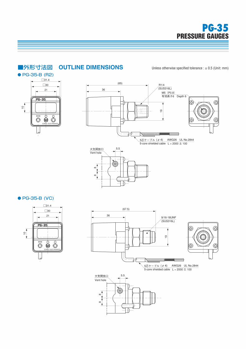
□31.4(67.5)
19
36
10
□30
大気開放口Vent hole
5.5
88
9/16-18UNF(SUS316L)
21
5芯ケーブル AWG26 UL No.2844L = 2000 ± 1005-core shielded cable
( 4)φ
□31.4(65)
19
36
10
□30
大気開放口 5.5
88
5芯ケーブル
R1/4(SUS316L)
M5(P0.8)有効長さ6 Depth 6
AWG26 UL No.2844L = 2000 ± 100
Vent hole
21
5-core shielded cable( 4)φ
PG-35PRESSURE GAUGES
■外形寸法図 OUTLINE DIMENSIONS Unless otherwise specified tolerance : ± 0.5 (Unit: mm)
● PG-35-B(R2)
● PG-35-B(VC)
対応機種 Applicable model
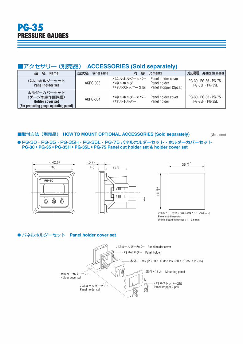
■アクセサリー(別売品) ACCESSORIES (Sold separately)品 名 Name 型式名 Series name 内 容 Contents
パネルホルダーカバー Panel holder coverパネルホルダー Panel holderパネルストッパー 2 個 Panel stopper (2pcs.)
PG-30 · PG-35 · PG-75 ·PG-35H · PG-35L
PG-30 · PG-35 · PG-75 ·PG-35H · PG-35L
パネルホルダーカバー Panel holder coverパネルホルダー Panel holder
ACPG-003
ACPG-004
パネルホルダーセットPanel holder set
ホルダーカバーセット(ゲージの操作面保護)
Holder cover set(For protecting gauge operating panel)
PG-35PRESSURE GAUGES
(□42.6) (5.7)4.5 23.5□40
36 +0.5 0
36+0
.5 0
パネルカット寸法(パネルの厚さ:1〜3.6 mm)Panel cut dimension(Panel board thickness : 1 ~ 3.6 mm)
● PG-30・PG-35・PG-35H・PG-35L・PG-75パネルホルダーセット・ホルダーカバーセットPG30 • PG35 • PG35H • PG35L • PG75 Panel cut holder set & holder cover set
パネルホルダーカバー Panel holder cover
パネルホルダー Panel holder
本体 Body (PG-30 • PG-35 • PG-35H • PG-35L • PG-75)
取付パネル Mounting panel
パネルストッパー2個Panel stopper 2 pcs.
ホルダーカバーセットHolder cover set
パネルホルダーセットPanel holder set
● パネルホルダーセット Panel holder cover set
■取付方法(別売品) HOW TO MOUNT OPTIONAL ACCESSORIES (Sold separately) (Unit: mm)

PG-35PRESSURE GAUGES
■特殊仕様品について Customization下記特殊仕様品の対応も可能です。詳細は営業担当者までお問い合わせ下さい。We also offer customized solutions. Please contact your local sales office for details.
型式Model number
外形、その他特殊仕様Shape and other customization
PG-35-102R-NR2-011 センサブラケット同梱Bracket (mounting plate) supplied
PG-35-102R-NR2-105
初期設定(kPa 表示、アナログ V モード(負圧出力)、セパレートモード)、圧力設定 :P1 -30kPa P2 50kPa 応差 10ms フィルタ F-0
Default mode (X 1 <multiplier factor>, V mode <analog output>, separate mode <switchoutput>), Pressure setting (P1:30kPa / P2 :50kPa, 10ms<hysteresis>, 0 (digital filter))
PG-35-102R-NR2B-128 付属品別梱包(パネルフォルダセット ACPG-003)添付Panel holder set (ACPG-003) separately packed and suuplied
PG-35-102R-PR2-021
大気圧導入チューブ同梱、クーラント侵入対策(ケーブルブッシュ部接着剤、パネルシート部保護シート)
Tube for vent hole supplied. Measures against coolant intrusion(application of epoxy around a cable bush, and protection cover for panel sheet)
PG-35-103R-NS2 継手 :1/4 スェージロックチューブ継手Fitting : 1/4 Swagelok tubing
●大気圧導入口のホースについて Tube at atmospheric pressure intakeセンサに水や油が大量にかかり、大気圧導入口からケース内部に入り込む恐れのある場合には、大気圧導入口にシリコンチューブなどを接続して他方を安全な所まで伸ばして下さい。この際チューブが折れ曲がったり、先端がふさがれないようにして下さい。
If there is any possibility that the sensor may become wet with oil or water, which may enter the case through the air intake, connect a silicon tube, or similar, to the intake and position the end of the tube in a suitably safe place. Be sure not to bend the tube or block the end of the tube.
●配管時について Pipingアルミダイカストにスパナ(13mm)をかけて、締付けは決してプラスチックケースをもって締め付けないでください。またエアリークの無い様に雄ネジ部にシールテープをご利用ください。取り付けアングルを本体に取り付けする場合(M3ネジ)の締めトルクは 0.3N・m 以下としてください。付属のシールネジ/ M5 継手ネジをご使用の際は、シールテープを 1.5 〜 2 周程巻き付けた上、ネジ山を破損しない様指で軽くネジ込んだ後、工具で増締めして下さい。樹脂ネジ推奨トルク:3.0N・m、金属ネジ推奨トルク:10.0N・m 以下
Use a wrench (13mm) on the aluminum die-casting. Do not hold the plastic case when tightening. Apply sealing tape at the male screw area to protect against air leaks. If mounting with an angled bracket, the maximum torque of the M3 screws should be less than 0.3N ·m.When using the accessories sealing or fitting screw, bind up the seal tape around the sealing screw one and a half or two turns, and screw it in the pressure port by hand without damaging the screw thread. After then, tighten the screw sufficiently with wrench.(Recommended torque:Plastic screw 3.0N·m, Metal screw 10.0N·m maximum)
■配管と設置の注意 Installation
外径φ4、内径φ2.5のチューブなど
Example of a tube with external diameter of φ4 and internal diameter of φ2.5


![Combo 3 в 1MD-163 - artway-electronics.comartway-electronics.com/instructions/ArtWay_MD-163_rukovodstvo_08... · 1 - Кнопка Power [Питание] регистратора](https://static.fdocuments.net/doc/165x107/5a86411c7f8b9a001c8ce9cd/combo-3-1md-163-artway-power-.jpg)