Pressure Equipment Calculator App - User Manual Equipment... · 1 INTRODUCTION Pressure Equipment...
17
PRESSURE EQUIPMENT CALCULATOR APP USER MANUAL Version 1.0 ©2020 – Maticon Consulting Engineers
Transcript of Pressure Equipment Calculator App - User Manual Equipment... · 1 INTRODUCTION Pressure Equipment...
PRESSURE EQUIPMENT CALCULATOR APP
USER MANUAL
Version 1.0
©2020 – Maticon Consulting Engineers
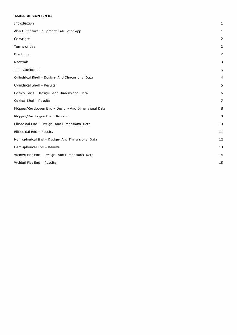
TABLE OF CONTENTS
Introduction
1
About Pressure Equipment Calculator App
1
Copyright
2
Terms of Use
2
Disclaimer
2
Materials
3
Joint Coefficient
3
Cylindrical Shell – Design- And Dimensional Data
4
Cylindrical Shell – Results
5
Conical Shell – Design- And Dimensional Data
6
Conical Shell - Results
7
Klöpper/Korbbogen End – Design- And Dimensional Data
8
Klöpper/Korbbogen End - Results
9
Ellipsoidal End – Design- And Dimensional Data
10
Ellipsoidal End – Results
11
Hemispherical End – Design- And Dimensional Data
12
Hemispherical End – Results
13
Welded Flat End – Design- And Dimensional Data
14
Welded Flat End – Results
15
1
INTRODUCTION
Pressure Equipment Calculator App – EN 13445, is a mobile application which calculates minimum thicknesses for pressure
equipment components, according to the European PED harmonized standard, EN 13445, for unfired pressure vessels.
The application covers calculation of:
-Cylindrical shells
-Conical shells
-Klöpper heads (torispherical heads)
-Korbbogen heads (torispherical heads)
-Elliptical heads
-Hemispherical heads and shells
-Welded flat ends
Calculations can be carried out for internal and external pressure in all modules.
Calculations are carried out for the design- and the testing situation.
Testing pressure is calculated according to EN 13445-5.
The application includes the possibility to calculate unreinforced openings in all modules.
Minimum distance between unreinforced opening and shell discontinuity are calculated.
For klöpper, korbbogen and elliptical heads it is possible to calculate openings in the knuckle region.
588 materials are included covering all parts of EN 10028 (plate), EN 10216 (seamless tubes) and EN 10217 (welded tubes).
Allowable stresses are calculated automatically based upon the given temperature and chosen testing group.
Warnings and errors are generated if criterions within EN 13445 are not fulfilled.
All calculated thicknesses are printed, with high-lightening of the maximum value.
There is a possibility to save, print or email the calculated results.
This tool can be used by manufactures during the preliminary design phase or when putting together an offer for a costumer.
Technical personal can easily obtain quick results during inspection of old, corroded, in-service pressure equipment.
The application can also be used during QA of the final technical documentation or by notified bodies/inspection agencies when
evaluating technical documentation.
ABOUT PRESSURE EQUIPMENT CALCULATOR APP
PE Calculator (EN 13445) has been developed by Maticon Consulting Engineers.
Current version: EN 13445-3:2014/Issue 5:2018.
For information about our services, help, and tutorials, please visit our website: www.maticon.eu
2
COPYRIGHTS
© 2020 Maticon. All rights reserved.
Maticon
Betonvej 10
DK-4000 Roskilde
Denmark
T: +45 32 100 200
W: www.maticon.eu
The product- and material standards: DS/EN 13445, DS/EN 10028, DS/EN 10216 and DS/EN 10217, has been used with kind
permission by the Danish Standard Foundation.
© DS 2020. All rights reserved. Unless otherwise specified, no part of this publication may be reproduced or utilized otherwise in
any form or by any means, electronic or mechanical, including photocopying, or posting on the internet or an intranet, without
prior written permission. Permission can be requested from DS at the address below.
Danish Standards Foundation
Göteborg Plads 1
DK-2150 Nordhavn
Denmark
T: +45 39 96 61 01
W: www.ds.dk
TERMS OF USE
PE Calculator (EN 13445) has been developed by Maticon and is intended to be used to estimate minimum thicknesses for
pressure equipment according to the European standard for unfired pressure vessel, EN 13445, using materials that are
harmonized with the European Directive for Pressure Equipment, 2014/68/EU.
Appropriate input values and materials must be used in order to obtain realizable calculation results.
DISCLAIMER
PE Calculator (EN 13445) has been developed by Maticon with main focus on accuracy and high quality in order to have a reliable
and well-functioning mobile application, but errors, inaccuracies, mistakes, malfunction, omissions etc. may occur.
The user shall, at any time, have the application updates enabled and ensure that all previous updates were installed in order to
ensure the application's proper functioning.
The user shall only use the application with compatible devices. Maticon shall not be responsible for any damages being a result
of improper use of the application, including, but not limited to, using the application on devices it was not designed for.
Maticon assumes no responsibility for errors, inaccuracies, mistakes, malfunction, omissions etc. in our mobile application or
documentation, examples and guidelines available from our website.
In no event shall Maticon be liable to the user or any third parties for any special, punitive, incidental, indirect or consequential
damages of any kind, or any damages whatsoever, including, without limitation, those resulting from loss of use, data or profits,
whether or not Maticon has been advised of the possibility of such damages, and on any theory of liability, arising out of or in
connection with the use of this mobile application.
The use of the mobile application is done at your own discretion and risk and with agreement that you will be solely responsible
for any damage to your operating system or loss of data that results from such activities. No advice or information, whether oral
or written, obtained by you from the Maticon or from the Maticon website shall create any warranty for the mobile applications.
3
MATERIALS
588 materials are included from the PED harmonized material standards:
-EN 10028, part 1 to 7 (plate material)
-EN 10216, part 1 to 5 (seamless tubes)
-EN 10217, part 1 to 7 (welded tubes)
Design- and testing stresses are calculated automatically acc. to EN 13445-3, Table 6-1, based upon the yield- and strength
values at the given temperature.
At high temperatures creep properties for the used material should be investigated. That is typically around, but not limited to,
370° C for ferritic steels and 425° C for austenitic steels. Design due to creep is not included.
A thickness range for the material must also be selected, as the yield- and strength values also depends upon the material
thickness. A sub-menu opens automatically when selecting the material.
JOINT COEFFICIENT
The joint coefficient depends upon the chosen testing group. EN 13445-5, Table 6.6.1-1 should be used to select a proper joint
coefficient.
The following joint coefficients are included in the Pressure Equipment Calculator app:
-1.00 Testing group 1 and 2 (Full NDT)
-0.85 Testing group 3 (Random NDT)
-0.70 Testing group 4 (No NDT)
-1.00 Seamless part
For austenitic, seamless, cold-spun torispherical ends, it is possible to select a special 1.00 joint coefficient, which can reduce the
thickness, compared to the regular 1.00 joint coefficient for seamless parts.
Some guidelines for choosing the testing group:
Testing group 4:
-Only group 2 fluids (non-dangerous fluids)
-max. 20 bar(g) internal pressure
-max. P·V (pressure · volume) 20.000 bar·liter above 100° C
-max. P·V (pressure · volume) 50.000 bar·liter up to 100° C
-non-cyclic pressure vessels (max. 500 full-pressure cycles)
-Only group 1.1 and 8.1 materials (see CEN ISO/CR 16508:2000)
-Max. 16 mm material thickness
Testing group 3
-Only group 1.1, 1.2, 8.1, 8.2, 9.1, 9.2, 10 materials (see CEN ISO/CR 16508:2000)
-Max. 30-50 mm material thickness
Testing group 1 and 2
-“Otherwise” (not suitable in testing group 3 and 4)
4
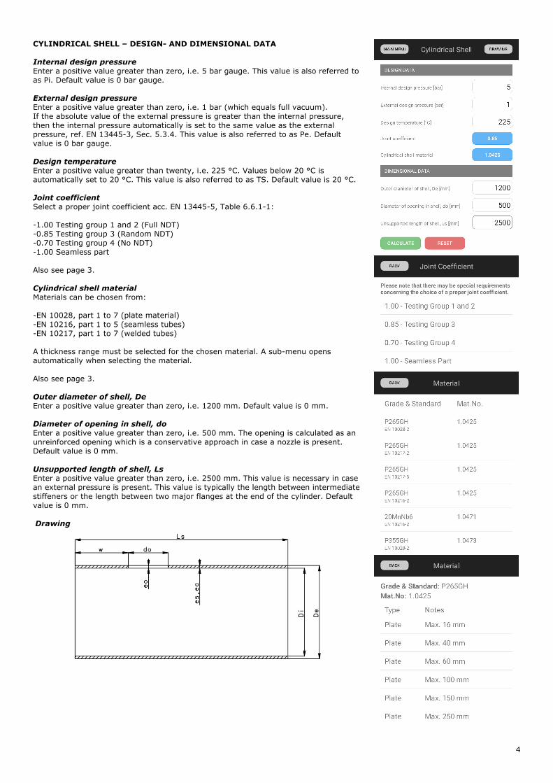
CYLINDRICAL SHELL – DESIGN- AND DIMENSIONAL DATA Internal design pressure
Enter a positive value greater than zero, i.e. 5 bar gauge. This value is also referred to
as Pi. Default value is 0 bar gauge.
External design pressure
Enter a positive value greater than zero, i.e. 1 bar (which equals full vacuum).
If the absolute value of the external pressure is greater than the internal pressure,
then the internal pressure automatically is set to the same value as the external
pressure, ref. EN 13445-3, Sec. 5.3.4. This value is also referred to as Pe. Default
value is 0 bar gauge.
Design temperature
Enter a positive value greater than twenty, i.e. 225 °C. Values below 20 °C is
automatically set to 20 °C. This value is also referred to as TS. Default value is 20 °C.
Joint coefficient
Select a proper joint coefficient acc. EN 13445-5, Table 6.6.1-1:
-1.00 Testing group 1 and 2 (Full NDT)
-0.85 Testing group 3 (Random NDT)
-0.70 Testing group 4 (No NDT)
-1.00 Seamless part
Also see page 3.
Cylindrical shell material
Materials can be chosen from:
-EN 10028, part 1 to 7 (plate material)
-EN 10216, part 1 to 5 (seamless tubes)
-EN 10217, part 1 to 7 (welded tubes)
A thickness range must be selected for the chosen material. A sub-menu opens
automatically when selecting the material.
Also see page 3.
Outer diameter of shell, De
Enter a positive value greater than zero, i.e. 1200 mm. Default value is 0 mm.
Diameter of opening in shell, do
Enter a positive value greater than zero, i.e. 500 mm. The opening is calculated as an
unreinforced opening which is a conservative approach in case a nozzle is present.
Default value is 0 mm.
Unsupported length of shell, Ls
Enter a positive value greater than zero, i.e. 2500 mm. This value is necessary in case
an external pressure is present. This value is typically the length between intermediate
stiffeners or the length between two major flanges at the end of the cylinder. Default
value is 0 mm.
Drawing
5
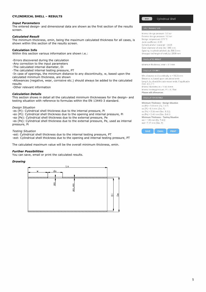
CYLINDRICAL SHELL – RESULTS Input Parameters
The entered design- and dimensional data are shown as the first section of the results
screen.
Calculated Result
The minimum thickness, emin, being the maximum calculated thickness for all cases, is
shown within this section of the results screen.
Calculation Info Within this section various information are shown i.e.:
-Errors discovered during the calculation
-Any correction to the input parameters
-The calculated internal diameter, Di
-The calculated internal testing pressure, PT
-In case of openings, the minimum distance to any discontinuity, w, based upon the
calculated minimum thickness, are shown
-Allowances (negative, wear, corrosive etc.) should always be added to the calculated
results
-Other relevant information
Calculation Details
This section shows in detail all the calculated minimum thicknesses for the design- and
testing situation with reference to formulas within the EN 13445-3 standard.
Design Situation
-es (Pi): Cylindrical shell thickness due to the internal pressure, Pi
-eo (Pi): Cylindrical shell thickness due to the opening and internal pressure, Pi
-ea (Pe): Cylindrical shell thickness due to the external pressure, Pe
-es (Pe): Cylindrical shell thickness due to the external pressure, Pe, used as internal
pressure, Pi
Testing Situation
-est: Cylindrical shell thickness due to the internal testing pressure, PT
-eot: Cylindrical shell thickness due to the opening and internal testing pressure, PT
The calculated maximum value will be the overall minimum thickness, emin.
Further Possibilities
You can save, email or print the calculated results.
Drawing
6
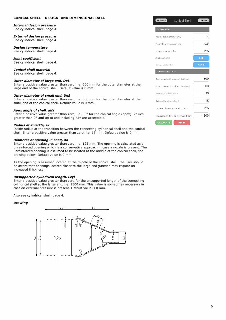
CONICAL SHELL – DESIGN- AND DIMENSIONAL DATA Internal design pressure
See cylindrical shell, page 4.
External design pressure
See cylindrical shell, page 4.
Design temperature
See cylindrical shell, page 4.
Joint coefficient
See cylindrical shell, page 4.
Conical shell material
See cylindrical shell, page 4.
Outer diameter of large end, DeL
Enter a positive value greater than zero, i.e. 600 mm for the outer diameter at the
large end of the conical shell. Default value is 0 mm.
Outer diameter of small end, DeS
Enter a positive value greater than zero, i.e. 300 mm for the outer diameter at the
small end of the conical shell. Default value is 0 mm.
Apex angle of shell, alfa
Enter a positive value greater than zero, i.e. 35° for the conical angle (apex). Values
greater than 0° and up to and including 75° are acceptable.
Radius of knuckle, rk
Inside radius at the transition between the connecting cylindrical shell and the conical
shell. Enter a positive value greater than zero, i.e. 15 mm. Default value is 0 mm.
Diameter of opening in shell, do
Enter a positive value greater than zero, i.e. 125 mm. The opening is calculated as an
unreinforced opening which is a conservative approach in case a nozzle is present. The
unreinforced opening is assumed to be located at the middle of the conical shell, see
drawing below. Default value is 0 mm.
As the opening is assumed located at the middle of the conical shell, the user should
be aware that openings located closer to the large end junction may require an
increased thickness.
Unsupported cylindrical length, Lcyl
Enter a positive value greater than zero for the unsupported length of the connecting
cylindrical shell at the large end, i.e. 1500 mm. This value is sometimes necessary in
case an external pressure is present. Default value is 0 mm.
Also see cylindrical shell, page 4.
Drawing
7
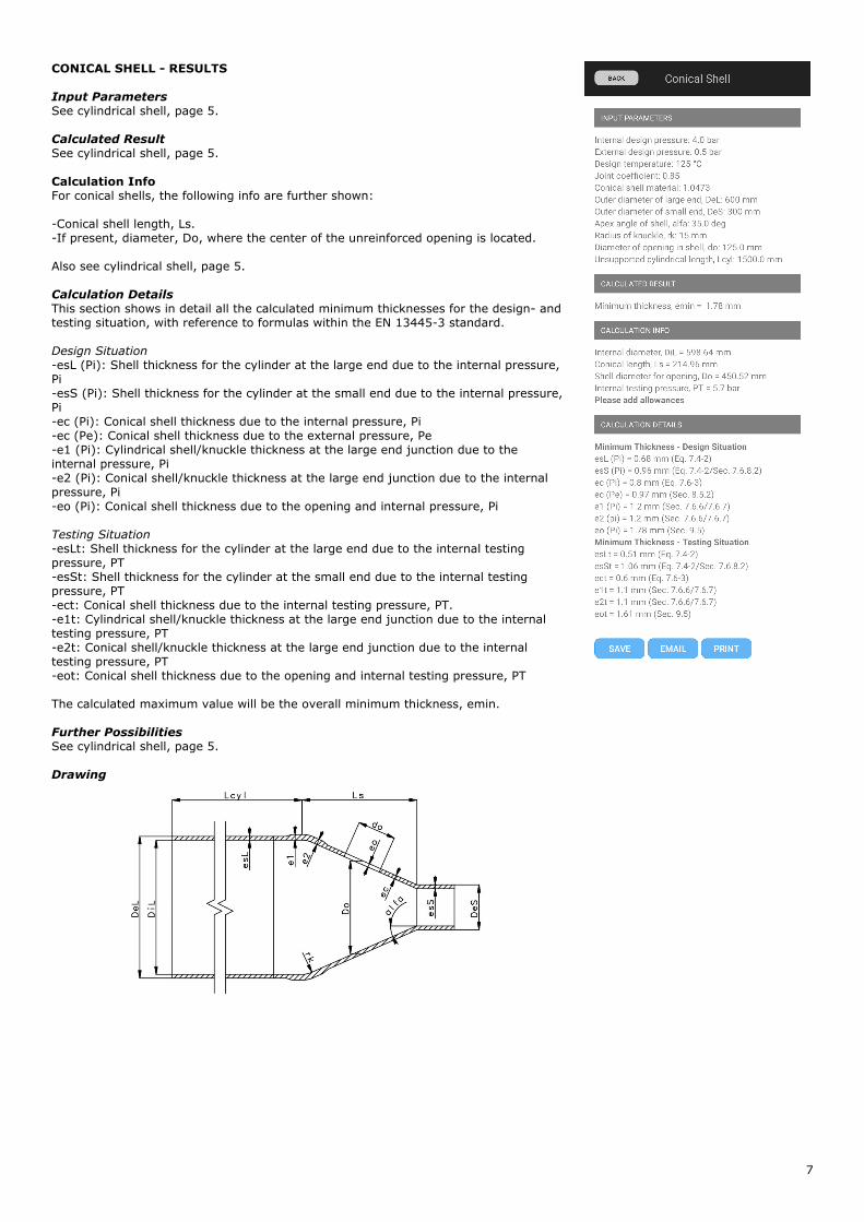
CONICAL SHELL - RESULTS Input Parameters
See cylindrical shell, page 5.
Calculated Result
See cylindrical shell, page 5.
Calculation Info For conical shells, the following info are further shown:
-Conical shell length, Ls.
-If present, diameter, Do, where the center of the unreinforced opening is located.
Also see cylindrical shell, page 5.
Calculation Details
This section shows in detail all the calculated minimum thicknesses for the design- and
testing situation, with reference to formulas within the EN 13445-3 standard.
Design Situation
-esL (Pi): Shell thickness for the cylinder at the large end due to the internal pressure,
Pi
-esS (Pi): Shell thickness for the cylinder at the small end due to the internal pressure,
Pi
-ec (Pi): Conical shell thickness due to the internal pressure, Pi
-ec (Pe): Conical shell thickness due to the external pressure, Pe
-e1 (Pi): Cylindrical shell/knuckle thickness at the large end junction due to the
internal pressure, Pi
-e2 (Pi): Conical shell/knuckle thickness at the large end junction due to the internal
pressure, Pi
-eo (Pi): Conical shell thickness due to the opening and internal pressure, Pi
Testing Situation
-esLt: Shell thickness for the cylinder at the large end due to the internal testing
pressure, PT
-esSt: Shell thickness for the cylinder at the small end due to the internal testing
pressure, PT
-ect: Conical shell thickness due to the internal testing pressure, PT.
-e1t: Cylindrical shell/knuckle thickness at the large end junction due to the internal
testing pressure, PT
-e2t: Conical shell/knuckle thickness at the large end junction due to the internal
testing pressure, PT
-eot: Conical shell thickness due to the opening and internal testing pressure, PT
The calculated maximum value will be the overall minimum thickness, emin.
Further Possibilities
See cylindrical shell, page 5.
Drawing
8
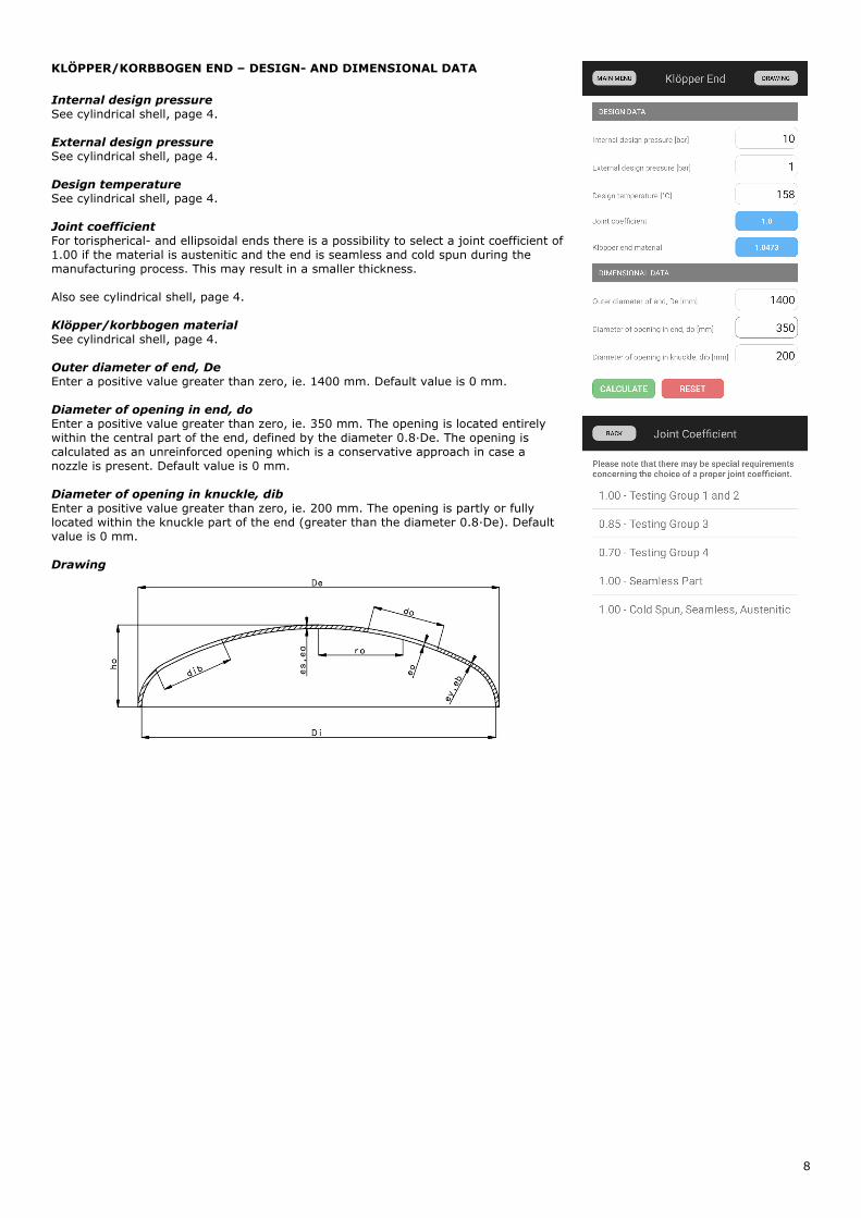
KLÖPPER/KORBBOGEN END – DESIGN- AND DIMENSIONAL DATA
Internal design pressure
See cylindrical shell, page 4.
External design pressure
See cylindrical shell, page 4.
Design temperature
See cylindrical shell, page 4.
Joint coefficient
For torispherical- and ellipsoidal ends there is a possibility to select a joint coefficient of
1.00 if the material is austenitic and the end is seamless and cold spun during the
manufacturing process. This may result in a smaller thickness.
Also see cylindrical shell, page 4.
Klöpper/korbbogen material
See cylindrical shell, page 4.
Outer diameter of end, De
Enter a positive value greater than zero, ie. 1400 mm. Default value is 0 mm.
Diameter of opening in end, do
Enter a positive value greater than zero, ie. 350 mm. The opening is located entirely
within the central part of the end, defined by the diameter 0.8·De. The opening is
calculated as an unreinforced opening which is a conservative approach in case a
nozzle is present. Default value is 0 mm.
Diameter of opening in knuckle, dib
Enter a positive value greater than zero, ie. 200 mm. The opening is partly or fully
located within the knuckle part of the end (greater than the diameter 0.8·De). Default
value is 0 mm.
Drawing

9
KLÖPPER/KORBBOGEN END - RESULTS Input Parameters
See cylindrical shell, page 5.
Calculated Result
See cylindrical shell, page 5.
Calculation Info For torispherical- and ellipsoidal ends the following info are further shown:
-Calculation notes
-Outer height of the end, ho
-If present, max. center radius, r, for the opening in the central part.
Also see cylindrical shell, page 5.
Calculation Details
This last section shows in detail all the calculated minimum thicknesses for the design-
and testing situation, with reference to formulas within the EN 13445-3 standard.
Design Situation
-es (Pi): Thickness of the spherical part of the end due to the internal pressure, Pi
-ey (Pi): Thickness of the knuckle to avoid axisymmetric yielding due to the internal
pressure, Pi
-eb (Pi): Thickness of the knuckle to avoid plastic buckling due to the internal pressure,
Pi
-eo (Pi): Thickness of the spherical part of due to the opening and internal pressure, Pi
-ea (Pe): thickness of the end due to the external pressure, Pe
-ey (Pe): Thickness of the knuckle to avoid axisymmetric yielding due to the external
pressure, Pe, used as internal pressure, Pi
Testing Situation
-est: Thickness of the spherical part of the end due to the internal testing pressure, PT
-eyt: Thickness of the knuckle to avoid axisymmetric yielding due to the internal
testing pressure, PT
-ebt: Thickness of the knuckle to avoid plastic buckling due to the internal testing
pressure, PT
-eot(Pi): Thickness of the spherical part of due to the opening and internal testing
pressure, PT
The calculated maximum value will be the overall minimum thickness, emin.
Further Possibilities
See cylindrical shell, page 5.
Drawing
10
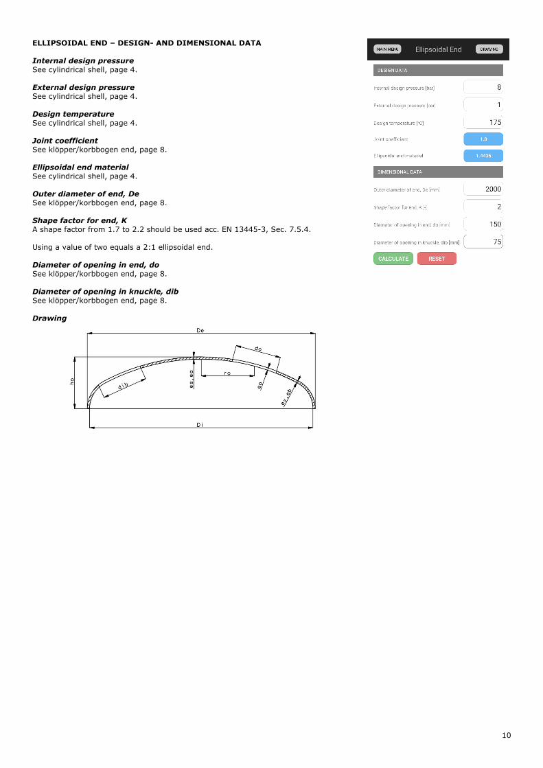
ELLIPSOIDAL END – DESIGN- AND DIMENSIONAL DATA Internal design pressure
See cylindrical shell, page 4.
External design pressure
See cylindrical shell, page 4.
Design temperature
See cylindrical shell, page 4.
Joint coefficient
See klöpper/korbbogen end, page 8.
Ellipsoidal end material
See cylindrical shell, page 4.
Outer diameter of end, De
See klöpper/korbbogen end, page 8.
Shape factor for end, K
A shape factor from 1.7 to 2.2 should be used acc. EN 13445-3, Sec. 7.5.4.
Using a value of two equals a 2:1 ellipsoidal end.
Diameter of opening in end, do
See klöpper/korbbogen end, page 8.
Diameter of opening in knuckle, dib
See klöpper/korbbogen end, page 8.
Drawing
11
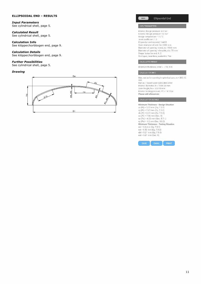
ELLIPSOIDAL END – RESULTS Input Parameters
See cylindrical shell, page 5.
Calculated Result
See cylindrical shell, page 5.
Calculation Info See klöpper/korbbogen end, page 9.
Calculation Details
See klöpper/korbbogen end, page 9.
Further Possibilities
See cylindrical shell, page 5.
Drawing
12
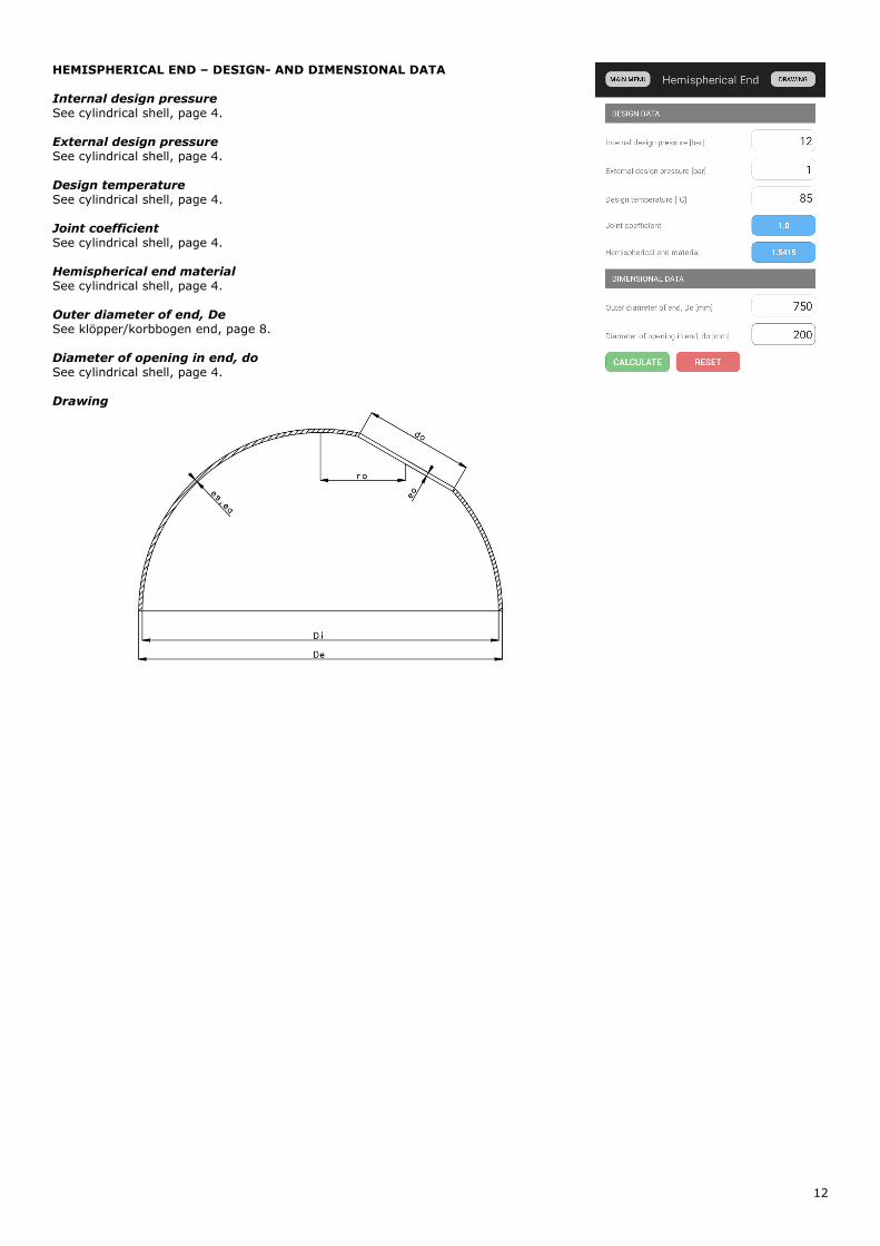
HEMISPHERICAL END – DESIGN- AND DIMENSIONAL DATA Internal design pressure
See cylindrical shell, page 4.
External design pressure
See cylindrical shell, page 4.
Design temperature
See cylindrical shell, page 4.
Joint coefficient
See cylindrical shell, page 4.
Hemispherical end material
See cylindrical shell, page 4.
Outer diameter of end, De
See klöpper/korbbogen end, page 8.
Diameter of opening in end, do
See cylindrical shell, page 4.
Drawing
13
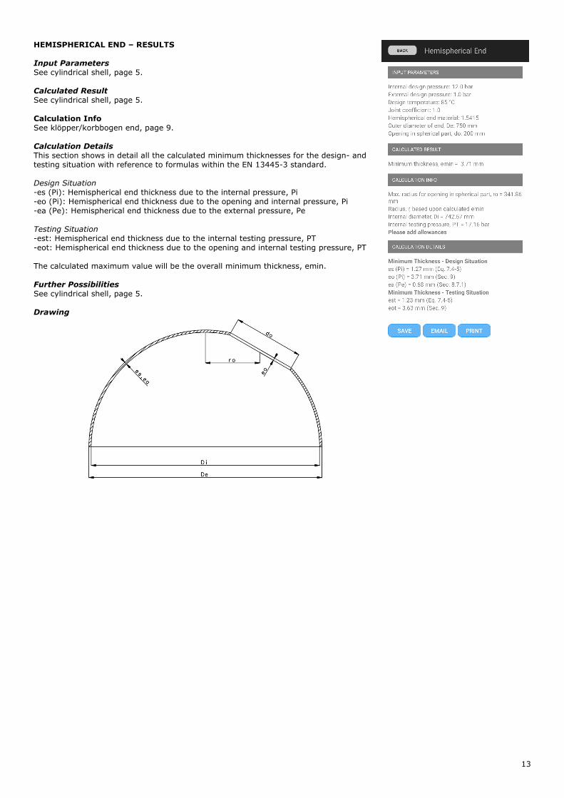
HEMISPHERICAL END – RESULTS Input Parameters
See cylindrical shell, page 5.
Calculated Result
See cylindrical shell, page 5.
Calculation Info See klöpper/korbbogen end, page 9.
Calculation Details
This section shows in detail all the calculated minimum thicknesses for the design- and
testing situation with reference to formulas within the EN 13445-3 standard.
Design Situation
-es (Pi): Hemispherical end thickness due to the internal pressure, Pi
-eo (Pi): Hemispherical end thickness due to the opening and internal pressure, Pi
-ea (Pe): Hemispherical end thickness due to the external pressure, Pe
Testing Situation
-est: Hemispherical end thickness due to the internal testing pressure, PT
-eot: Hemispherical end thickness due to the opening and internal testing pressure, PT
The calculated maximum value will be the overall minimum thickness, emin.
Further Possibilities
See cylindrical shell, page 5.
Drawing
14
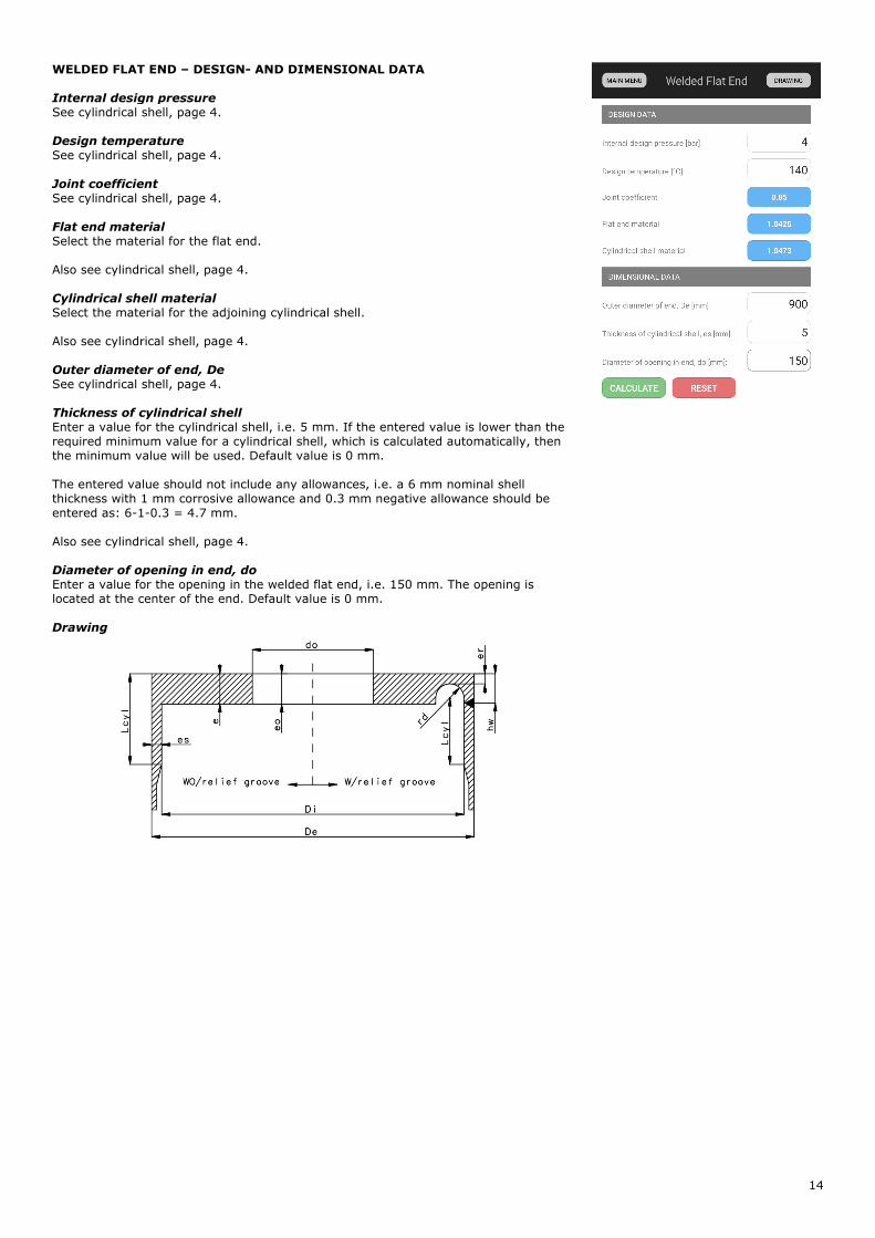
WELDED FLAT END – DESIGN- AND DIMENSIONAL DATA Internal design pressure
See cylindrical shell, page 4.
Design temperature
See cylindrical shell, page 4.
Joint coefficient
See cylindrical shell, page 4.
Flat end material
Select the material for the flat end.
Also see cylindrical shell, page 4.
Cylindrical shell material
Select the material for the adjoining cylindrical shell.
Also see cylindrical shell, page 4.
Outer diameter of end, De
See cylindrical shell, page 4.
Thickness of cylindrical shell
Enter a value for the cylindrical shell, i.e. 5 mm. If the entered value is lower than the
required minimum value for a cylindrical shell, which is calculated automatically, then
the minimum value will be used. Default value is 0 mm.
The entered value should not include any allowances, i.e. a 6 mm nominal shell
thickness with 1 mm corrosive allowance and 0.3 mm negative allowance should be
entered as: 6-1-0.3 = 4.7 mm.
Also see cylindrical shell, page 4.
Diameter of opening in end, do
Enter a value for the opening in the welded flat end, i.e. 150 mm. The opening is
located at the center of the end. Default value is 0 mm.
Drawing
15
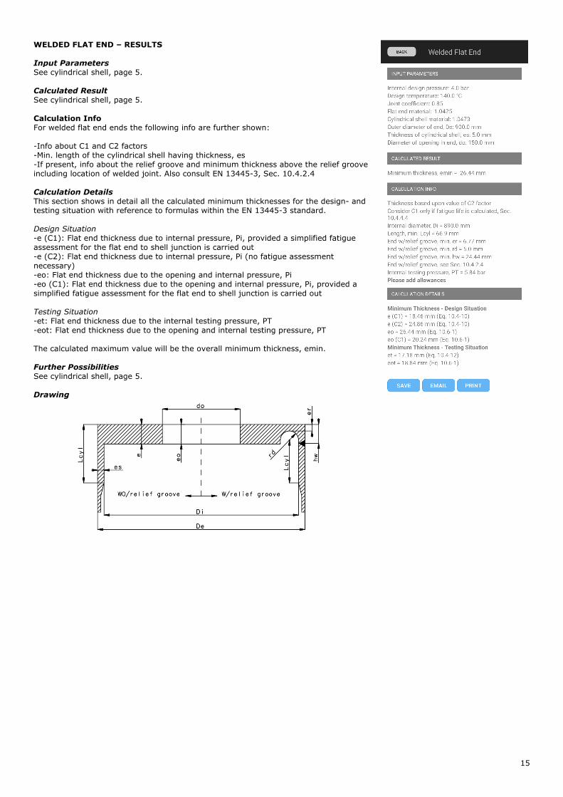
WELDED FLAT END – RESULTS Input Parameters
See cylindrical shell, page 5.
Calculated Result
See cylindrical shell, page 5.
Calculation Info For welded flat end ends the following info are further shown:
-Info about C1 and C2 factors
-Min. length of the cylindrical shell having thickness, es
-If present, info about the relief groove and minimum thickness above the relief groove
including location of welded joint. Also consult EN 13445-3, Sec. 10.4.2.4
Calculation Details
This section shows in detail all the calculated minimum thicknesses for the design- and
testing situation with reference to formulas within the EN 13445-3 standard.
Design Situation
-e (C1): Flat end thickness due to internal pressure, Pi, provided a simplified fatigue
assessment for the flat end to shell junction is carried out
-e (C2): Flat end thickness due to internal pressure, Pi (no fatigue assessment
necessary)
-eo: Flat end thickness due to the opening and internal pressure, Pi
-eo (C1): Flat end thickness due to the opening and internal pressure, Pi, provided a
simplified fatigue assessment for the flat end to shell junction is carried out
Testing Situation
-et: Flat end thickness due to the internal testing pressure, PT
-eot: Flat end thickness due to the opening and internal testing pressure, PT
The calculated maximum value will be the overall minimum thickness, emin.
Further Possibilities
See cylindrical shell, page 5.
Drawing