PressCam 8 Junior and PressCam 8
20
Punch Press Automation Controllers www.pressroomelectronics.com D1 Punch Press Automation Controllers PressCam 8 Junior and PressCam 8
Transcript of PressCam 8 Junior and PressCam 8

Punch Press Automation Controllers www.pressroomelectronics.com D1
Punch Press Automation Controllers
PressCam 8 Junior and PressCam 8

Punch Press Automation Controllers www.pressroomelectronics.com D2
PressCam 8™ PressCam 8™Junior
Diagnostic Display Vacuum MonochromeFluorescent LCD Display
(4 lines/20 characters) (8” diagonal screen)
Ease of Programming Cursor/Key Pad Tuning Knob
Control Reliable System No Yes
Limit Switch Outputs 6 11
Die Protection Inputs 6 16
Number of (non-timed) events per 2 3 crank rotation
Number of Jobs Stored in Memory 100 100
Memory Chips Removable (sockets) Yes Yes
Brake and Die Sensor Inputs Yes Yes optically coupled AC or DC (sourcing or sinking)
Length of Name of Job (characters) 7 13
Motion Detection Yes Yes Lack of (Motion Fault) Unintended (Drift Fault)
Brake Monitoring (Time-Based) Yes Yes
SPM Indicator Yes Yes (strokes per minute)
Servo Feed Interface Yes Yes
Counters: Yes Yes Stroke, Batch, Quality, and Part
Password and/or Supervisory Yes Yes Controlled Selector Switch
PCLink to allow off-line Yes Yes job storage and creation
Speed Compensation of User Yes Yes Selected Outputs
Tonnage monitoring N/A Optional
Resolver & Cable Supplied Yes Yes
Built-in 90º and 270º stop time tester Yes Yes
For OSHA and ANSI Compliant Clutch/Brake Press Controls, please see the PressCommander.
Punch Press Automation Feature Comparison of PressCam 8 Junior and PressCam 8
PressCam 8 Junior
PressCam 8

www.pressroomelectronics.com Punch Press Automation Controllers D3 Punch Press Automation
PressCam 8 Junior Layout
• AllsixLimitSwitchOutputscanbesettocycle(non-timed)twotimespercrankrotationbysettinganopen/closecrank angle.
• Thelastthreeoutputscanbesetfortimed,non-timed,delayed,andholdorcycledtwotimespercrankrevolution. • MajorfaultssuchasE-Stop,motion,brake,andsensorfaultsarehandledbytwoforce-guidedrelays(FormBSafety
relays). • Thesixoutputsaresmall,high-speed,high-capacityrelays. • BrakeanddiesensorinputsareopticallycoupledandcanbeeitherACorDC(sourcingorsinking). • Upto100Jobscanbesavedusinganonvolatilememorychip.Thememorychipisremovableforeaseoftransfer.EachJobNumberstoresanameand/ornumberupto7charactersforeasyidentification.
• Built-inBrakeMonitorwillissueawarningwhentheprogrammedwarningtimeisexceededandwillissueafailuresignalwhenprogrammedstoptimeisexceeded.
• TrueMotionDetectionsystemchecksforlackofmotion(MotionFault)andunintendedmotion(DriftFault). • SPMIndicator(StrokesperMinute). • Crankangleshowngraphicallyandinlargenumbers. • Speedcompensationofuserselectedoutputs. • Servofeedinterface. • Stroke,Batch,Quality,andPartCounterstokeeptrackofoperation. • Passwordand/orSupervisoryControlledSelectorSwitchtopreventalteringofparameters,exceptforthecounters. • PCLinktoallowofflinejobcreationandstorage. • Built-in90ºand270ºstoptimetester.
Design Features
VacuumFluorescent Display
4 lines/20 characters Alphanumeric

Punch Press Automation Controllers www.pressroomelectronics.com D4
The PressCam 8 Junior is a resolver-based press automation controller that incorporates a programmable cam limit switch, timed-based brake monitor, servo feed control, four counters, and a die protection system. The PressCam 8 Junior is controlled by a 16-bit computer that constantly checks the resolver for accuracy.
The PressCam 8 Junior has a keypad, menu, cursor buttons (for easy navigation and operation), and a four line (20 characters each line) vacuumfluorescentdisplayforeasyviewingpurposes.
A “RUN/PROG” keyswitch is also provided where, while in the “RUN” mode, you are not able to alter any parameter or job change. The “RUN” mode only allows the user to clear counters and reset die sensor faults. In the PROG mode, the Die Faults do not open up the fault relays which allows for die setups. All other faults will cause the fault relays to open. Ifthepasswordfeatureisenabled,youmustfirstenterinthethreedigitpassword in order to pass into the PROG mode to allow parameter changes.
Punch Press AutomationPressCam 8 Junior
The heavy duty brushless resolver transducer replaces the current me-chanical rotary cam switch. This unit was designed for hostile industrial environmentssuchaspunchpressmechanicalshockandvibration,ex-treme temperature and humidity, oil, coolant, and lubrication mists. The resolvertransducerfeaturesexcellentrepeatabilityandgivesabsoluteshaft position feedback. High speed operation along with long trans-ducer cable (runs up to 600 feet/183m) give the resolver transducer wide application ranges. The resolver transducer is a passive device which contains no sensitive electronics and has superb noise immunity.
The resolver mounts easily to an end of a crankshaft and can rotate clockwise or counter-clockwise. Simple connector ended transducer ca-bling is supplied to connect the resolver to the PressCam 8 Junior con-troller console. The PressCam 8 Junior’s microprocessor-based control constantly monitors the resolver position and displays both the angular position of the shaft and speed of the machine (tachometer).3/4” (19 mm) resolver shaft diameter.
Overview
Industrial Grade Brushless Resolver Transducer

www.pressroomelectronics.com Punch Press Automation Controllers D5
Input Power: 3 Voltage Ranges: 24VDC (optional)120VAC (standard) 240VAC (optional, jumper selectable)All AC voltages work with 50 or 60 Hz 10 watts with all relays on
Fuses:I/O Board: F1 to F8 LS Outputs 5A Fast Blow (20-023)
F7 Power 1A Slow Blow (20-022)F9 to F15 Die Inputs 5A Fast Blow (20-023)F35 12VDC 5A Fast Blow (20-023)
Computer: F1 Power 5A Fast Blow (20-023)Indicators:Computer: Vacuum Fluorescent 4 lines/20 characters
-5V (GRN) D10
I/0 Board: 8 Optically coupled inputs (RED):Power ON D22 Brake D21 Die 1-6 D15-D20 6 LS Outputs (GRN) LS1-6 D1-D6
Set Points:Stroke Count: 0 to 999,999 strokesBatch Count: 0 to 999,999 strokesQuality Count: 0 to 999,999 partsPart Count: 0 to 4 parts/stroke
0 to 999,999 parts totalBatch Size: 0 to 999,999 strokesLimit switch angle: 0 to 359 degreesLimit switch timer: 0 to 9999 millisecondsDie sensor angle: 0 to 359 degreesSpeed Compensation 0 to 99 degreesMinimum Speed: 0 to 999 SPMMaximumSpeed: 0to999 SPMBrake Warning: 1 to 999 millisecondsBrake Failure: 1 to 999 millisecondsBrake Actual: 1 to 999 milliseconds (+/-1 millisecond accuracy)Motion: 0 to 5.9 seconds (1/10-sec increments)Drift: preset to 2 SPM (1/10 SPM increments)Crank Angle: 0 to 359 degrees (1-degree increments)SPM: 0 to 999 strokes/minute (+/- 1 SPM accuracy)
Resolver+/- 1º Resolution up to 600 RPM (+/- 2º Resolution from 601 to 1000 RPM) Shaftloading:Radial400lbs.,Axial200lbs.-3/4”(19mm)diametershaftStandardcable30'(9m).Maximumlengthof600’(183m).
Punch Press Automation PressCam 8 Junior
Specifications
ConstructionStand Alone Unit: All 18 gauge painted steel NEMA 12lockableboxwithsealedfrontpanel Dimensions: 7 1/4” (184mm) width; 9”(229mm) height; 3 1/4” (83mm) depth
Panel Mount Unit: All 18 gauge painted steel NEMA 12 with gasket around edge. Dimensions: 6 1/2” (165mm) width; 7 1/8” (181mm) height
Temperature Range
0 to 50ºC
Punch Press Automation Controllers www.pressroomelectronics.com D6 Punch Press AutomationPressCam 8 Junior
Main ScreenThe Main Screen allows for Job Selection and Naming, Parts, and Batch Count.
Job: 00
Parts: 000000Batches: 000000Angle: 000 SPM: 000
Brake MonitorIn RUN Mode, the screen dis-plays the Last Stop Time (in mSEC) and Last Dwell angle (in degrees). Last Stop Time= 000 Last Stop Time= 000
In PROG mode, the original screen is displayed but with the Dwell angle added to the bottom line of the screen.
Warn= 000 Fail= 000Motion Det= 0.0 sec90º - 270º test Dwell= Time= 000
CounterThe PressCam 8 Junior provides four types of counters: Stroke, Batch, Quality, and Part. When programmed, a counter will incre-ment each time a part is ejected from the machine. When the programmed value is met, the controller will initiate an action.
Strokes: 000000 Parts: 000000 /1Batch size: 000000 Quality: 000000
Servo FeedEach PressCam 8 Junior job stores individual Servo Setup information and outputs through the RS-232 every time the unit is powered up, afteryouexitfromtheServoSetupscreen and after a job change. The Servo Setup screen can be accessed only while in PROG mode.
Speed 1-100: 000 Accel 1-100: 000 MPC 1-100: 000 Feed Len.: 000.000
Press UtilityThis screen allows you to program the following settings: speed compensations, minimum speed, maximumspeed,clearjob,topdeadcenter, PC link, and set password.
Speed comp: 000 Min= 000 Max= 000ClrJob SetTDCPCLink Pasword 000
Limit SwitchesThe following screen monitors the statusofallsixrelayoutputsaswellas displays the current crank angle.
LS1 LS4 LS2 LS5 LS3 LS6 ANGLE: 000 MONITOR
Cyclical Outputs
S CLS-OPN CLS-OPN LS1 000-000 000-000LS2 000-000 000-000LS3 000-000 000-000
S CLS-OPN CLS-OPN LS4 000-000 000-000LS5 000-000 000-000LS6 000-000 000-000
Cycle Delay & Hold Outputs
DLY CY HLD CY LS4 000 000LS5 000 000LS6 000 000
Timed Outputs
STRT ANG HLDmSEC LS4 000 0000LS5 000 0000LS6 000 0000
Die InputA unique name can be created forsixdiesensors(SEN1-SEN6)in the PROG mode while viewing the die monitor screens.
TYPE BGN END SEN1 MOM 000-000SEN2 MOM 000-000SEN3 MOM 000-000
TYPE BGN END SEN4 MOM 000-000SEN5 MOM 000-000SEN6 MOM 000-000
The Die Status Screen allows you to run the press and see when die sensors activate relative to press angle.
SEN1 * SEN4SEN2 SEN5 *SEN3 * SEN6ANGLE: 000 MONITOR

www.pressroomelectronics.com Punch Press Automation Controllers D7
The PressCam 8 Junior is a resolver-based press automation controller that incorporates a programmable cam limit switch, timed-based brake monitor, servo feed control, four coun-ters, and a die protection system The PressCam 8 Junior is controlled by a 16-bit computer that constantly checks the resolver for accuracy.
PressCam 8 Junior (all styles, Front panel & Stand alone). Includes resolver and cable
ORDERING PROCEDURE
1. Specify Mounting StyleF.........FrontPanelMountingtobeinstalledinanexistingcontrolpanel.C ......... Stand alone NEMA12 enclosure
2. Specify Controller input power1 .......... 24VDC2 .......... 120VAC 50-60Hz3 ........... 240VAC 50-60Hz
3. Specify Clutch/Brake Valve Voltage1 .......... 24VDC
2 .......... 120VAC 50-60Hz 4. Resolver Connector Cabling
30’ (9m) of cable with connectors is supplied standard. If additional length is needed, specify infeet,150’(46m)maximum.
EXAMPLE PART NUMBER
JR - C - 2 - 1 - 30’Mounting Style Input Power Clutch/Brake
Valve Voltage
Part Number Description 30-012 [email protected](90-260vacIn)3.9”Lx3.8”Wx1.4”H(99.1mmx96.5mmx35.6mm) forpoweringdieprotectionsensorsorotherauxiliarydevices
Punch Press AutomationPressCam 8 Junior Overview/Ordering Procedure
(For Custom Programming & Remote Field Upgrades, please consult factory at [email protected] or (630) 443-9320.)
Resolver Cable
Punch Press Automation Controllers www.pressroomelectronics.com D8
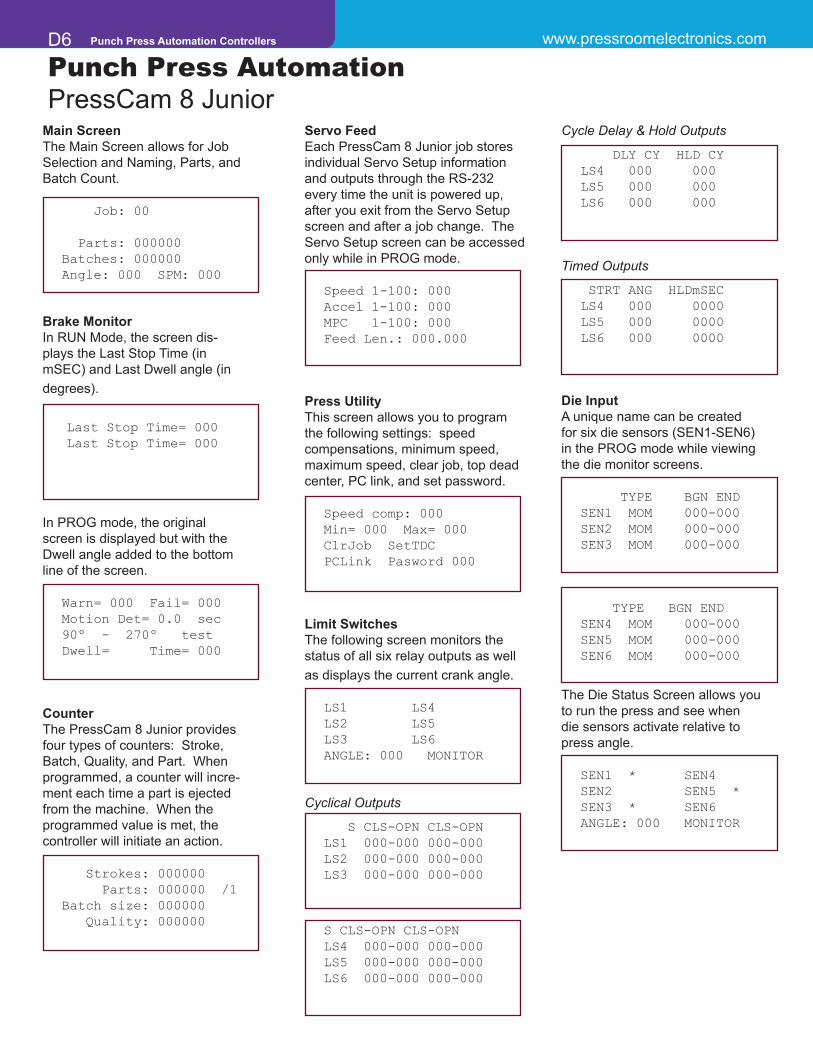
REPLACEMENT PARTS LISTING
Part Number Description 11-157 Panel Mount (with gasket) 11-158 MetalBoxenclosure(withgasket)11-160 Aluminum Shield cover for computer board
18-008 Vacuumfluorescentdisplay(mustbefactoryinstalled)
20-022 1A Slo-Blo nano SMF fuse 20-023 5A Fuse (white nano)
26-084 Graphic overlay skin
32-002 Output Relay (black G6B-1174P)32-006 Output Relay (black G6B-2114P) 32-101 4 pole 12 VDC (clear KACO safety relay)
35-065 EEPROM Job memory chip (100 jobs)
39-084 RUN/PROG keyswitch, key, and cable
45-020 Resolver cable (30’) with connectors
52-205 Junior computer board (with job memory)52-206 Junior Power supply / Relay output board (with relays and fuses)52-227 Resolver unit (no cable) (formerly 40-003)
Punch Press Automation PressCam 8 Junior

www.pressroomelectronics.com Punch Press Automation Controllers D9
Punch Press AutomationPressCam 8 Junior
Dimensions
PressCam 8 Junior shown installed in a stand alone NEMA 12 (IP64) lockable enclosure
PressCam 8 JuniorFront Panel MountCut-Out Dimensions
Resolver Transducer
3.5
9.6875 hole to hole
0.75
0.30
7.254.50
7.1000
6.5000
2.2500
1.6250
2.8740
0.1500
1.000
3.5004.5200
MS3102E16S-1P Conn.
1.000
4.7500
0.2750 Diameter
0.6250
0.7500
1.2500
4.5200
2.5200
2.5200

Punch Press Automation Controllers www.pressroomelectronics.com D10
Punch Press AutomationPressCam 8
Design Features• “ControlReliable”design,utilizingtwo16-bitcomput-
ers, provides ultimate pressroom safety in automa-tion.
• Operator“fullview”ofsystemstatusmeansnoget-ting lost during programming.
• PressCam8’stwo16-bitcomputersareconfiguredtocross check each other and the resolver.
• Allsafetyfunctionfaultsutilizethreemonitoredcap-tive contact safety relays for the outputs related tomotion detection, brake monitoring, and system self -checking (Form B safety).
• Non-volatilejobmemoryof100storedprogramsrecalled by job die number for all system functions.
• Elevenprogrammablelimitswitchoutputswithmul-tipleON/OFFs per press cycle.
• Outputscanbesolidstate(ACorDC)ormechanicalrelays.
• SupervisorycontrolledRUN/PROGkeyswitchwithpassword protection.
• Built-intime-basedbrakemonitorcanissuewarn-ings or a stop command when actual stopping timeexceedsprogrammedsetpoints.
• Built-inmotiondetectionfaultoutputshouldthepressnot start moving within the timed set point after thebrake signal is given.
• Built-indriftdetectionfaultoutputifthepressmoveswhen it should not.
• Built-in90ºand270ºstoptimetester.
• PressCam8’scloningfeatureallowsmultiplePress-Cam 8 units to link via RS-232 for job copying.
• ContrastadjustmentoftheLCDcomputerscreen.
• Automaticoffsetprogramming.
• Built-inpresstachometer(SPM).
• OpticallyisolatedACand/orDCinputs(sourcingorsinking).
• Partscounterwhichcanbeprogrammedfrom1-4parts per press cycle for multiple out dies.
• Large8”(203mm)diagonalcomputerscreen(LCD).
• UniquedigitalprogrammingknobactslikeaPCmouse and eliminates keypad programming.
• The“controlreliable”PressCam8canbeusedtosupply the timing signals for the clutch/brake presscontrol.
• CompletesystemdiagnosticswithplainEnglishfaultmessages on the operator screen enhances produc-tivity.
• PressCam8programscanbefieldupgradedorcus-tomized using a PC computer with a standard serialport.
• Fourprogrammabletimedlimitswitchoutputsthatcan be position based or timed from 0 to 9999 mil-liseconds.
• FourCounters:Strokes,Parts,Batch,andQuality.
• Built-inpowersupplyforinputsensors(+12VDC).
• Built-inservofeedinterface.
• Crankshaftangledisplayedindegreeswithagraphic shaft angle clock.
• Utilizessurfacemounttechnology.
• Jobmemorychipsaresocketedforeasytransfertoother units if desired.
• Programmableminimumandmaximumspeedlimitswith captive contact safety relay output (Form Bsafety).
• Programmablevariablespeedcompensation.
• Punchpressclutch/braketimingsignalsprotectedfrom tampering.
• Optionalpeaktonnagemonitoringupto4channels.
• Compactinsize.

www.pressroomelectronics.com Punch Press Automation Controllers D11
Punch Press Automation PressCam 8
Overview
PressCam 8 is a “control reliable” resolver-based programmable cam switch, time-based brake monitor, die protection systemwithmultiplecountersandmuchmoreinonepackage.Thesystemcontainstwo16-bitcomputersthatareconfig-ured to cross check each other and the resolver. The dual computers are interfaced with a full view 8" (203mm) diagonal LCDcomputerscreenforviewingandprogrammingease.Thislargeoperatorscreen(shownonthenextpage)suppliesoperators and front line supervisors production data without the need of cumbersome menu and program access codes.
AllsystemfaultsgeneratedescriptiveplainEnglisherrormessagesonthecomputerscreen.Thisprovidesfloorpersonnelfast and reliable information related to the machine stoppage. The system is also provided with special watchdogs that turn off fault outputs should either computer become erratic. The software and system customization in both computers canbeupgradedinthefieldusingaPCcomputerwithastandardserialport.
Programming PressCam 8 is so easy that you do not need a keypad, keyboard, or cumbersome programming tech-niques.
A large 8" (203mm) diagonal LCD computer screen is standard equipment on the PressCam 8. This single component brings the intelligence of the dual computer system to the punch press control panel providing positive system status interaction with the machine operator.
The screen brightness (contrast) is also adjustable so it can be easily read even when installed in dark areas.
Operator Screen
Digital Programming Knob
This innovative device replaces keypads or keyboards for programming the PressCam 8. The programming knob works similartoacomputermouse.Simplyturntheknobtothehighlightedfieldorprogramyoudesirethenpush.Yourprogramis accessed with no keystrokes. By turning the knob, the appropriate numbers or letters appear on the highlighted screen toprogramthespecificfunctionyoudesire.Pushagain,yourprogrammingiscompleted!Additionally,noinformationcanbeprogrammedifitisnotapplicabletothespecificfunctionoroperation.
Industrial Grade Brushless Resolver Transducer
The heavy duty brushless resolver transducer replaces the current mechanical rotary cam switch. This unit was designed forhostileindustrialenvironmentssuchaspunchpressmechanicalshockandvibration,extremetemperatureandhumid-ity,oil,coolantandlubricationmists.Theresolvertransducerfeaturesexcellentrepeatabilityandgivesabsoluteshaftposition feedback. High speed operation along with long transducer cable (runs up to 600 feet/183m) give the resolver wide application ranges. The resolver is a passive device which contains no sensitive electronics and has superb noise immunity.
The resolver mounts easily to an end of a crankshaft and can rotate clockwise or counter-clockwise. Simple connec-tor ended transducer cabling is supplied to connect the resolver to the PressCam 8 controller console. The PressCam’s microprocessor-based control constantly monitors the resolver position and displays both the angular position of the shaft and speed of the machine (tachometer). 3/4” (19 mm) resolver shaft diameter.

Punch Press Automation Controllers www.pressroomelectronics.com D12
Programming Screen
Punch Press Automation PressCam 8
Shown above is the actual screen size and information available to the press operator on the PressCam 8 Programming Screen. No longer is it necessary to scroll through various menus and programming techniques to view data. The Programming Screen also provides an active “tool bar” for your press set-up per-sonnel to quickly access the specific functionthey so desire. As one can see, a tremendous amount of production data can be obtained by simply viewing this single operator screen.
System simplicity is a dominant feature of the PressCam 8. By viewing the above screen, information can be obtained for four differ-ent counters, reset all faults, adjustment for screen contrast, die protection information, programmable limit switch information, shaft angle displayed in degrees, stroke per min-ute (SPM), and brake monitoring information.
Additionally, system fault messages are displayed in the area above the brake monitor setpoint section when they occur.
Screen Actual Size
www.pressroomelectronics.com Punch Press Automation Controllers D13
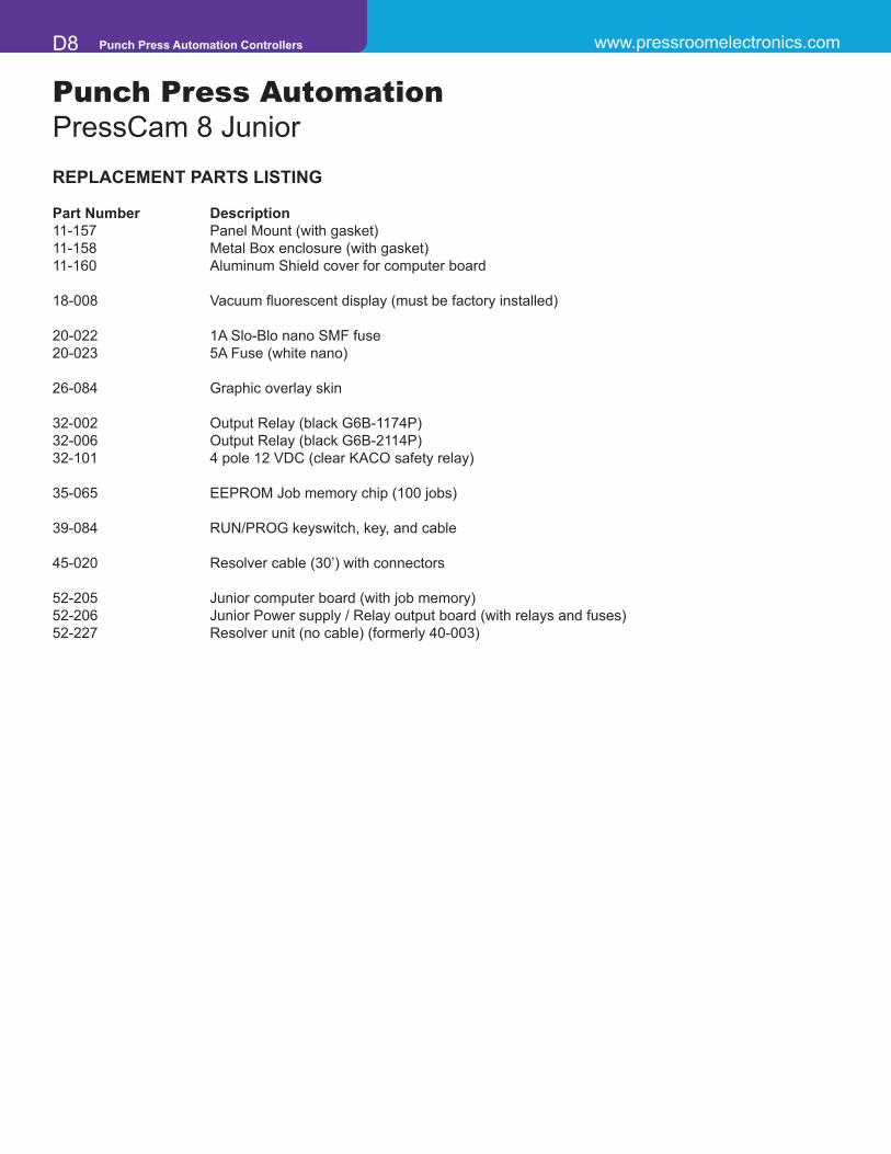
Die Protection
Punch Press AutomationPressCam 8
Screen Actual Size
The Die Protection Screen shown above is what your programmer will see when entering the die protec-tion program. PressCam 8 provides sixteen differ-ent die protection sensor inputs that may be pro-grammed for both cyclic and/or static function monitoring.
Cyclic function monitoring requires that an input sen-sor signal occur within a certain programmed shaft angle on each press cycle (e.g., part eject, part transfer).
Static monitoring is used for non-cycl ic events such as end of material or stock buckle monitoring.
A fault output will occur if an input transition is not detected between the programmed limit set points (e.g., a part is to be ejected out of the die between 190º and 250º of the machine cycle). If the part is not detected within these pa-rameters, a fault or stop signal is given to stop the machine.
To program, simply turn to “die-sensor set-up” and de-press the programming knob. Now you are in the die protection program. Then put in the parameters in de-grees when you would want to look for the part to eject or transfer. From 190º to 250º is when the sensor will be looking for the part. That is all there is to programming die protection. If a fault output occurs, simply view the screen and determine from what sensor the fault occurred.
The die protection program can be fine tuned while the machine is in motion along with related peripheral signals such as feeds, lubrication, blowoffs, etc. This is an ex-cellent method of increas-ing the machines efficiency.

Punch Press Automation Controllers www.pressroomelectronics.com D14
Programmable Limit Switch
Punch Press Automation PressCam 8
Screen Actual Size
Limit switch programming simplicity is a PressCam 8 feature.
PressCam 8 crank angle position is generated by a heavy duty industrial resolver driven by the press crank shaft.
PressCam 8 provides the user with eleven program-mable limit switch outputs used to initiate various pe-ripheral equipment. These outputs can be programmed to turn on and off up to three times per press cycle.
The programmable limit switch outputs may be me-chanical relay, solid state AC, or solid state DC. The solidstaterelaysmaybemixedonthesamerelayboard.
The Delay and Hold cycle feature provides control for lubrication systems, scrap choppers, etc. This provides you with signals when you need events to occur on a pre-programmed intermittent (time) or multiple stroke basis.
Limit switches 1 – 7 can be programmed to turn ON and OFF up to three times per press cycle. Limit switches 8 – 11 can be programmed to turn ON and OFF up to two
times per press cycle or may be programmed to turn ON based on angle and OFF based on time. The timed outputs can be programmed from .001 to 10 seconds. Furthermore, these switches may be used with the Delay and Hold cycle feature which provides control for items that need not be initiated on every press cycle but a programmed number of press cycles. Or they can be held ON for a pre-programmed number of press cycles.
Aminimumandmaximumspeed limitsettingcanbeused tomonitor optimum running speed versus actual. A deviation outside the programmed parameters will initiate a stop signal.
The system includes a true motion detection system that monitors the press cycle. If you tell the press cycle and it fails to move within the pre-programmed time (.001 to 4 seconds), a fault signal is is-sued. On the opposite side, if the press starts to cycle without ini-tiation, a fault signal is issued to electrically disconnect all signals.
The clutch/brake timing signals can also be password-pro-tected from inadvertent tampering by unauthorized personnel.

www.pressroomelectronics.com Punch Press Automation Controllers D15
Tonnage Screen
Punch Press AutomationPressCam 8
The TLM I/0 load module is designed for critical force mea-surementapplicationswhereaccuracy,extremestability,and dependable noise rejection is essential. The module is a load measurement device without a display or alarms. The TLM is used as an input device to the PressCam 8 providing display and alarm control functions.
The TLM has high sensitivity levels that work well in an electrically“noisy”environment.Ithastwoamplifiergainranges (span ranges). Therefore, it can accept either weak or strong signals from the load sensor.
Features• Signalconditioningmoduleforstraingauge
sensors and load cells• Fourindependentchannelsforaccommodat-
ing up to eight sensors• Forusewithfull-bridgesensorsfrom120
Ohms to 1,000 Ohms• Plug-inconnectorsareusedforthesensor
inputs• High/lowsensitivityspanrangesselected
with front panel switch• Automaticzerobalancecircuitsassureac-
curate measurements• Powerinput/outputareplug-inconnectors• Built-inautomaticpeakloadmemorycircuits• Peakmeasurementsaremadewithanex-
ternal trigger device• Built-inpowersupplyforstableoperation
and noise rejection• Compactsizetofitalmostanylocation• Steelenclosureformaximumprotectionand
noise rejection
Transducers Full Bridge, 120 Ohms to 1,000 Ohms. One to fourchannelversionavailable.Maximumoftwo350Ohmssensors per channel.Dimensions2"(51mm)x3.1"(79mm)x8.95"(227mm)Balance Range +/- 1 mV/V of offsetGain ‑ Two Ranges Low = 100 to 1,100 adjustable High = 1,000 to 11,000 adjustableOutput Range Approximately+/-10VDCat12VDCexcitationCircuit Accuracy Maximuminaccuracyof+/-1%offullscaleCircuit Linearity Maximumnon-linearity+/-.1%offullscaleAuto Zero Time Constant 10 secondsFrequency Response Flat DC to 1 KHz
Peak Decay Lessthan1%offullscalein10minutesCalibration Shunts 1MegOhm,.1%Input Power 100 to 130VAC 50-60 Hz. Fused at .10 Amp. 200 to 260VAC 50-60 Hz. Fused at .05 Amp. Inputisjumperselectable.Fusesare5mmx 20mm SLO-BLO.Sensor Excitation Internallyexcitedat+12VDC,.30AmpsmaximumSensor Input Connections Four pin .2” (5mm) centers PhoenixconnectorPeak Output Connections Sixpin.2"(5mm)centersPhoenixconnectorProximity Probe 12VDC internally supplied to drive NPN orPNPprobes,50mAmax.Inputalsosupportsdryrelaycontacts.
Specifications

Punch Press Automation Controllers www.pressroomelectronics.com D16
Input Power: 3 Voltage Ranges: 1) 24VDC (optional) 2) 120VAC (standard) 50 or 60 Hz 3) 240VAC (optional) 50 or 60 Hz 24 watts with all relaysInput Control Unit: Monochrome LCD 8" (203mm) Diagonal Display Display • LCDBIAS (GRN) D16 • Vpp (YEL) D8 • 5VDC (GRN) D14I/0 Board: +12 VDC (RED) D2 17 Optically Coupled Inputs 13 Solid-State or Mechanical Relay Outputs 3 Force-Guided Monitored Safety Relay Outputs (Form B)Relays: Mechanical - SPDT Form C AC Solid State - SP N.O. 10 AMP @ 260VAC 3 AMP @ 140VAC 10 AMP @ 30VDC 12-14VAC 25-70 Hz Mechanical Captive Contact - Form B DC Solid State - SP N.O. 8 AMPS @250VAC 3 AMP @ 60VDC 12-60 VDCSet Points: Stroke Count: 0 to 999,999 strokes Batch Count: 0 to 999,999 strokes Quality Count: 0 to 999,999 parts Part Count: 1 to 4 parts/strokes (programmable) 0 to 999,999 parts total Batch Size: 0 to 999,999 parts Limit Switch Angle: 0 to 359 degrees Limit Switch Timers: 0 to 9999 milliseconds Die Sensor Angle: 0 to 359 degrees Minimum Speed: 0 to 300 SPM MaximumSpeed: 0to300SPM Brake Warning: 1 to 999 milliseconds Brake Failure: 1 to 999 milliseconds Brake Actual: 1 to 999 milliseconds (+/- 1 ms accuracy) Start Motion: 0 to 5.9 seconds (1/10 sec increments) Crank Angle: 0 to 359 degrees (1 degree increments) SPM: 0 to 300 strokes/minute (+/- 1 SPM accuracy)Components: • PressCam 8 Master Controller Panel Mount 10.8"(274mm)Wx11.8"(300mm)Hx2.5"(64mm)D • PressCam 8 Master Controller mounted in a Stand Alone NEMA 12 Enclosure 11"(279mm)Wx13.1"(333mm)Hx5"(127mm)D • Resolver Transducer +/- 1º Resolution up to 700 RPM +/- 2º Resolution from 701-1000 RPM 3/4" (19mm) keyed shaft Rated shaft loading: 200lbs.axial400lbs.radial Weight: 4 lbs. Shock: 200 G for 11 msec Vibration: 20g to 2000 Hz Operating Temp: -20º to 125ºC Enclosure: NEMA 13 Transducer to master controller: 600'(183m)max Rotation: CW or CCW Resolver Cable: 30’ (9m) supplied standard with connectorsDiagnostics: Complete system diagnostics on LCD screenEnclosure 18 gauge painted steel NEMA 12 lockable enclosure with sealed front panel orConstruction: open frame for panel mounting.
Punch Press Automation PressCam 8
Specifications

www.pressroomelectronics.com Punch Press Automation Controllers D17
Punch Press Automation PressCam 8 Overview/Ordering Procedure
PressCam 8 is a "control reliable" resolver based programmable cam switch, time-based brake monitor, die protection system, multiple counters, and much more in one package. The system containstwo16-bitcomputersthatareconfiguredtocrosscheckeachotherandtheresolver.The dual computers are interfaced with a full view 8" (203mm) diagonal LCD computer screen for viewing and programming ease. This large operator screen supplies operators and front line supervisors production data without the need of cumbersome menu and program access codes.
PressCam 8 (all styles, Front panel & Stand alone). Includes resolver and cableORDERING PROCEDURE
1. Specify Mounting StyleF.........FrontPanelMountingtobeinstalledinanexistingcontrolpanel.C ......... Stand alone NEMA12 enclosureT .......... Stand alone NEMA12 enclosure with room for the Tonnage Module
2. SpecifyOutputRelays(13maximum)M ......... Mechanical Dry contact relays SPDT 10A@250VACA ......... AC Solid State - single Pole N.O. 3A@140VAC, 12-140VAC, 25-70HzD .......... DC Solid State - single Pole N.O. 3A@60VDC, 12-60VDC
3. Specify Controller Input power1 .......... 24VDC2 .......... 120VAC 50-60Hz3 ........... 240VAC 50-60Hz
4. Specify Clutch/Brake Valve Voltage1 .......... 24VDC
2 .......... 120VAC 50-60Hz5. Resolver Connector Cabling
30’ (9m) of cable with connectors is supplied standard. If additional length is needed, specify infeet,150’(46m)maximum.
6. Specify Tonnage Monitoring (optional)T1 ......... One Channel monitoring with strain sensor and cableT2 ......... Two Channel monitoring with strain sensor and cableT3 ......... Three Channel monitoring with strain sensor and cableT4 ......... Four Channel monitoring with strain sensor and cable
TONNAGE MONITORING (OPTIONAL)
T1 One channel monitor module with strain sensor and cable T2 Two channel monitor module with strain sensor and cableT3 Three channel monitor module with strain sensor and cable T4 Four channel monitor module with strain sensor and cable
EXAMPLE PART #PC8 - C - - - - 1 - 1 - 30’ - T4Style Mounting
StyleOutput Relays
Clutch/Brake Valve
Voltage
ResolverOutput Relays
Output Relays
Input Power
Mechanical
AC
Solid StateDC
Solid State
Part Number Description 30-012 [email protected](90-260vacIn)3.9”Lx3.8”Wx1.4”H(99.1mmx96.5mmx35.6mm)
forpoweringdieprotectionsensorsorotherauxiliarydevices.
(For Custom Programming & Remote Field Upgrades, please consult factory at [email protected] or (630) 443-9320.)
Tonnage

Punch Press Automation Controllers www.pressroomelectronics.com D18
REPLACEMENT PARTS LISTING
Part Number Description 11-131 Panel Mount (with gasket)11-132 LCD mounting bracket (blue) 11-133 Aluminum Shield cover for computer board11-134 MetalBoxenclosure(withgasket)11-135 Solid State Relay hold-down for I/O board11-159 LargeMetalBoxenclosure(includesspaceforTTLMmodule)
18-005 B/W LCD display panel (with backlight) 18-006 LCD Backlight power supply 18-007 LCDBacklightfluorescenttube
20-022 1A Slo-Blo nano SMF fuse20-023 5A Fuse (white nano)
21-047 Tuning Knob (black knob)21-048 Tuning Knob (black ring)
26-071 Graphic overlay skin
30-009 Replacement Tonnage Controller (3 or 4 channel input unit) 30-010 Replacement Tonnage Sensors & 35’ of cable 30-013 Replacement Tonnage Controller (1 or 2 channel input unit)
32-038 Output Module (Solid State AC) 32-039 Output Module (Solid State DC)32-041 Output Relay (G2R-1-S) 32-101 4 pole 12 VDC (clear KACO safety relay)
35-065 EEPROM JOB memory chip (50 jobs) (2 chips are required for 100 jobs) (2 chips are required for 100 jobs)
39-051 RUN/PROG Keyswitch (with keys and cable)
40-002 Tuning Encoder device
45-019 LCD cable (from LCD to Computer board) 45-020 Resolver cable (30’) with connectors
52-115 Power & I/O board (without output modules) specify solid-state or relay 52-116 Dual Computer board (with 100 job memory) 52-122 I/O ribbon cable (from I/O board to Computer board) 2’52-123 Power cable (from I/O board to Computer board) 2’ 52-227 Resolver unit (no cable) (formerly 40-003) 52-282 Serial to Ethernet Board for PressCam 8
Punch Press AutomationPressCam 8

www.pressroomelectronics.com Punch Press Automation Controllers D19
PressCam 8 shown installed in a stand alone NEMA 12 (IP64) lockable enclosureDimensions for the Tonnage version of the PressCam 8 are 14.5”(368mm)Wx13.1”(333mm)H
PressCam 8Front Panel Mount
Punch Press AutomationPressCam 8
Dimensions
0.1500
1.000
3.5004.5200
MS3102E16S-1P Conn.
1.000
4.7500
0.2750 Diameter
0.6250
0.7500
1.2500
4.5200
2.5200
2.5200
Resolver Transducer
5” (127mm)
11.6” (295mm)
.75” (19mm)
.312” (8mm)
11” (279mm)
7” (178mm)
11.8” (300mm)
10.8” (274mm)
.7” (18mm)
.8” (20mm)2.1132”
(54mm)
1.75” (44mm)
.626” (16mm)
7.348” (187mm)
1.276” (32mm)1.625” (41mm)

Additional products to achieve your Total Safety Solution!!!- Safety Light Curtains (All Types and Styles)- Universal Safety Controller HUB / Safety PLC- Safety Mat Systems and Controls
- Area Guarding Systems- NSD Safety Mat Systems- STTS Safety Mat Systems- Direction of Travel Mats- High-Temp Welding Mats
- Ergonomic Palm Buttons- UltraTouch Palm Buttons
- Safety Interlock Switches (including explosion proof)- Customized “control reliable” controls for dual solenoidactivated pneumatic and hydraulic valve applications- Fencing with Interlocks- E-Stop Buttons- Stack Lights
- Energy Isolation and Single Point Lockout Systems- Plant Surveys, Risk Assessment & Installation Services- Customized Control Panels; Stainless Steel enclosures
available for all productsPunch Press / Metal Stamping Industry
- Resolver or Rotary Cam Based Clutch / BrakeControls - OSHA/ANSI Compliant
- Punch Press Automation Controllers- Time-Based Brake Monitors- Programmable Limit Switches- Die Protection & Tonnage Monitoring Systems- Servo Feed Interfaces
Press Brake Guarding and Controls- Press Brake Guarding for Mechanical, Air Clutch
and Hydraulic Press Brakes- Press Brake Control Systems
Sales and Marketing OfficeP.O. Box 99875Pittsburgh, PA 15233
Phone: (412) 262-1115Fax: (412) 262-1197
[email protected] [email protected]
Manufacturing and Service Center1510 Hubbard Ave.Batavia, IL 60510 USA
Phone: (630) 443-9320Fax: (630) 443-9346
We have designed our equipment to the veryhighest performance and safety standardsknown to the current technological state of the art, as evidenced by our U.S.A. and foreign patents issued and pending. However, the installation, usage, and suitability, and fitness of our equipment for any purpose, known or unknown, is interdependent upon the performance of other equipment not manufactured, installed, secured or maintained by Pressroom Electronics.
We cannot and do not accept responsibility for any overall system performance when factors such as these, are beyond our control.