Presplitting in Wet Ground – Techniques and Design ...
23
Presplitting in Wet Ground – Techniques and Design Considerations ISEE Conference November 2018
Transcript of Presplitting in Wet Ground – Techniques and Design ...

Presplitting in Wet Ground –Techniques and Design Considerations
ISEE Conference
November 2018
Presplitting in Open Cut Coal Mining
2
• Presplits are a blasting technic to aid in the creation of safe stable highwalls essential for open cut mining operations
• The aim of a presplit is to create a fracture plane within the rock along what will be the future highwall
• This discontinuity will then intercept the radial cracking and gas propagation from the main production blast
• Results in a clean blast interface
Presplitting in Open Cut Coal Mining
3
• Preferential growth of cracks created by the shock wave interactions between holes and the pressure increase developed within the borehole during detonation create the presplit crack
• Because of this, hole timing, spacing and charge weight are all equally critical to the development of a good presplit
• The borehole pressure generated within the presplit should be less than the compressive strength of the rock but greater than the tensile strength of the rock
• The pressure created from a fully charged hole is too high
• Introducing an air deck within the hole decouples the explosives from the rock and reduces the borehole pressure to some more useful
Decoupling of Explosive Charge
4
• �� = 110 × �� × �� × ���� - Cunningham (2006)
• � = !"#$%&'() �*"+#, = -./0
-123×
4./05
41235
• �� explosive density
• VOD of the explosive deck
Explosive
Air
Lexp
LairF�
FGH4
×,�
�
,GH4�
1
F�
FGH4
×,�
�
,GH4�
1rair
rexp

Decking Method
5
• Standard method for creating a decked charge is to load bulk product directly into the hole.
• Decks held in place through the use of gas bags
• Initiation of all decks is completed by a single line of detonating cord threaded through all primers
• Decked charge introduced every 15-20m depending on the strata
• Hole are not stemmed
• Coal seam does not require prespittingtherefore a standoff is maintained to reduce energy loss through the coal seam
Charge Placement
6
• Borehole pressure is not linear throughout a decked hole
• As decked charges in contact with the wall of the holes, a crushing effect can be still present at the location of the charges
• Consideration of the strata is important to the charge placement within the blast hole
• Charges placed in weak bands or tertiary material will have a reduced effect

Timing Sequence
7
• Ideally a presplit would be fired with no delays to maintain optimal p wave interaction between boreholes
• Overpressure then becomes an issues
• Delays used to limit the MIC to something comparable to that of a production blast, usually around 10 holes.
• Usually a 17ms delay between groups
Presplitting and Midsplitting
8
• Standard terminology – Presplit refers to the firing of the single row prior to the firing of the production pattern. Midsplit refers the firing of the presplit and production together.
• Holes are tied into the pattern using nonel surface delays firing sequentially around 100-300ms prior to the adjacent production holes
• Holes still fired in groups in quick succession, 9ms inter hole delay
• As the holes are not fired instantaneously the P wave and pressure interaction between holes is significantly reduced
• As a consequence the quality of a midsplit highwall generally does not match that of a presplit highwall
Effects of Joints and Faulting
9
• The reduced rock strength around geological features makes presplitting more difficult
• Horizontal bedding and fractures have minimal effect but vertical fractures can have a significant effect depending on the angle with respect to the highwall
• Reduced spacing and charge size required for heavily faulted areas
• Design of the production blast and its powder factor, and burden relief will have the ultimate effect on the wall outcome in these areas
• Consider if the area is conducive to presplitting at all
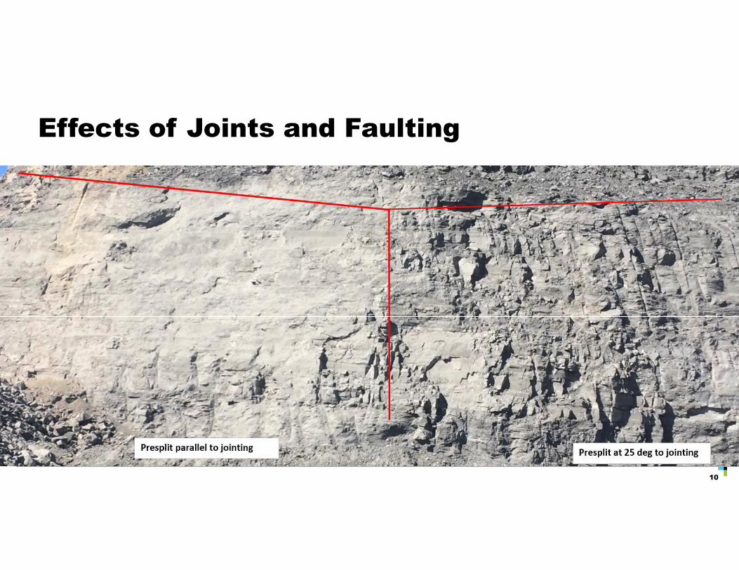
Effects of Joints and Faulting
10
Issue faced at Jellinbah
11
• Presplit holes vary in depth from 25m up to 65m depending on the pit and seam
• Water levels varied throughout the site. In some areas 60m holes contain up to 55m of water
• Gas bags cannot be installed into wet holes due to their buoyancy
• Dewatering holes not practical due to the recharge rate
• Using only a single large charge at the base of the holes would lead to a poor quality wall in holes over 30m.
• Packaged charges are not suitable due to the cost and storage constraints given the large size of some presplit patterns.
Solution – Introduction of Charge Bags
12
• PR Polymers KoolKap Bikini Bags used create decked charges in wet holes
• Each bag allows for up 100kg of bulk product to be contained within it
• The bags are threaded onto the detonating cord downlines with a separate compartment to contain the booster
Charge Bag Decking Method
• Bag positioned at the hole collar and rope attached to handle
• Bag primed with the booster and detonating cord
• Bags loaded via the use of a 1 inch hose from the MPU
• The bags are lowered by rope into place through the use of a lowering unit
• Also lowered by hand if the holes are full of water or the charge size is reduced and using the buoyancy of the bag
• Rope tied off onto a large wooden stake once the charge is at the desired depth
13
Additional Benefits Achieved
14
• Increased accuracy of the depth of the charge placement, can be repositioned if needed
• 1 inch hose used to load the bags allows more accurate product delivery method. Previously it was found lowering the product hose for large depth leads to over charging as the hose contents is discharged on retraction.
• Useful for holes with muddy walls as it removes the issue of product clinging to the sides of the holes during loading augured product
Use of charge bags in mid-splitting
15
• Midsplits are fired using nonel downhole and surface delays to allow for integration with rest of a standard nonel production blast
• Charge bags are not recommended to be loaded using nonel downhole accessories due to risk of snapping the downlines.
• Down hole delay scatter would also be an issue if the holes contained water. If the bottom charge were to fire before the top charge it could displace the top charge as it is coupled to it via the water in hole.
• To overcome this holes are loaded as per standard procedure using detonating cord and then connected via a 600ms down hole delay to connect it to the rest of the pattern.

Design Considerations For Wet Holes
16
• Water within the hole will act a coupling medium between the charges and the blast hole walls
• This increases the efficiency in which the explosive pressure is exerted onto the blast hole walls
• Hydraulic blasting has been explored in other areas such as small scale dimension cutting in quarries and oversize blasting
• Water will also wedge into the radial fractures generated in the surrounding rock during detonation, amplifying fracture propagation
• The use of water coupled blasting in an underground presplit application reported an improved result despite a 30% reduction in charge size – Yang (2017)

Water Coupled Charges in Presplit
18
• As the hole is detonated via detonating cord initiation is near instantaneous but the decks do fire from top to bottom
• The top charge ejects the water above it. The water has a slight stemming effect, compared to air, dependent on the amount of water present.
• Water between top deck and subsequent decks becomes pressurised increasing the pressure throughout the hole walls
• Water moves through rock structure and out the top of the hole until the pressure equalises
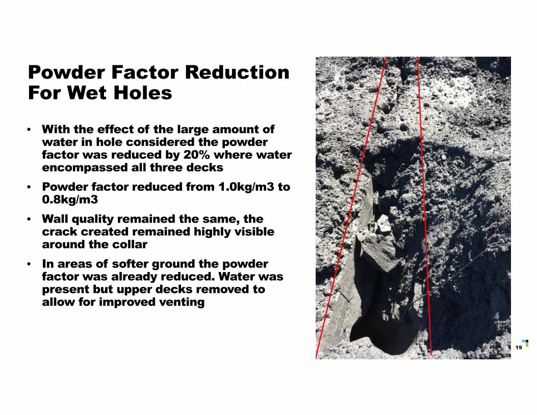
Powder Factor Reduction For Wet Holes
19
• With the effect of the large amount of water in hole considered the powder factor was reduced by 20% where water encompassed all three decks
• Powder factor reduced from 1.0kg/m3 to 0.8kg/m3
• Wall quality remained the same, the crack created remained highly visible around the collar
• In areas of softer ground the powder factor was already reduced. Water was present but upper decks removed to allow for improved venting
Faults and the Effect of Water
20
• As the presence water increases the borehole pressure, area of low rock strength will be prone to additional blast damage
• Water movement will also be focussed into faults as the low tensile strength allows the path of least resistance to these areas
• Lowering charge size alone is not adequate if a large amount of water is present
• In areas of geological structures, holes were left uncharged to allow for venting of gas and water
• Venting effect only spreads to the immediately adjacent holes when firing the presplit. Therefore only every second hole was left uncharged
• Gas and water ejections confirms this in video playback
• Ideally hole spacing would also be reduced in these areas however the precise location of the faults hard to determine until the touch coal data is obtained from drilling the presplit
Midsplitting and the Effect of Water
21
• Difficult to quantify if a reduction is powder factor due to the presence of water is warranted due to the diminish wall quality achieved through a midsplit anyway
• Depending on the time a midsplit will usually fire around 2 burden widths before the production blast.
• This ground movement from production blast could be enough to allow for a drop in water level and therefore pressure.
• A lower water pressure on the production side of the blast could then negate the pressure increase within the midsplit hole as it equalises towards the production holes and away from the highwall

Conclusion
22
• Use of the charge bags allowed for increased accuracy of presplits in both charge placement and size
• Water has a significant effect on the borehole pressure and how it is applied to the rock throughout the hole. As seen in the reduction in powder factor
• Two decks can be fully coupled together via water. Removing the upper decks allows for increased venting
• The use of entirely uncharged venting holes has a an effect but only for a limited area of influence. Fracture plane still continues through if every second hole is loaded

23
Thank you
www.downergroup.com
www.downerblasting.com
References1. Snachidrian, J. A., Garcia-Bermudez, P., Jimeno C.L., “On Borehole pressure and spacing in cautious blasting with an
extension to water-filled holes,” International Journal of Blasting and Fragmentation vol 2 pp235-248, 1998
2. Yang, J., Liu, C. Y., “Experimental Study and Engineering Practice of Pressured Water Coupling Blasting,” HindawiShock and Vibration Vol 2017 Article ID 5484598
3. Yang, J., Liu C., Yu, B., ‘”Application of Confined Blasting in Water-Filled Deep Holes to Control Strong Rock Pressure in Hard Rock Mines,” Energies MDPI 2017
4. McKenzie, C.K., “Limits Blast Design: Controlling vibration, gas pressure and fragmentation,” Rock Fragmentation by Blasting 2013
5. Cunningham, C. “Blasthole Pressure: What it really means and how we should use it”, 32nd Annual Conference on Explosives and Blasting Technique, ISEE, Grapvine, TX, 2006
24