Presentazione GPIB- PXI- VXI -Parte II
33
31 Measurement Hardware: Stand-Alone Buses Measurement Hardware Instrument Control Buses • Serial (RS-232) • Ethernet • USB • IEEE 1394 We now continue the discussion of the hardware layer by presenting other stand-alone instrument control buses. © National Instruments Corporation Instrument Control – The Future of GPIB, VXI and PXI
-
Upload
alejandro-soto-altamirano -
Category
Documents
-
view
16 -
download
0
Transcript of Presentazione GPIB- PXI- VXI -Parte II
31
Measurement Hardware: Stand-Alone Buses
Measurement Hardware
Instrument Control Buses
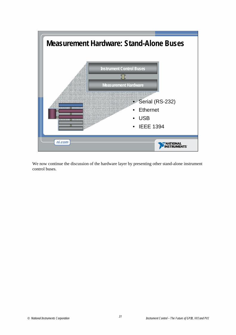
• Serial (RS-232)• Ethernet• USB• IEEE 1394
We now continue the discussion of the hardware layer by presenting other stand-alone instrument control buses.
© National Instruments Corporation Instrument Control – The Future of GPIB, VXI and PXI
32
Serial (RS-232) – Basics
• Interface for connecting peripherals to PCs– Typically used for connecting mice, joysticks, etc.
• Can achieve up to 28.8 kB/s rates (230.4 kb/s)• Used for scientific and laboratory instrument control
– For example, scales, barcode readers, etc.• Inexpensive to implement
– RS-232 UART built into most microprocessors
The serial or RS-232 bus is commonly used for connecting peripherals such as mice and keyboards to PCs. In instrument control, it is mostly used for controlling laboratory and analytical types of instruments such as scales and barcode readers. It currently can achieve transfer rates up to 28.8 kBytes/s or 230.4 kbits/s (higher rates can be achieved with different transceivers). The main benefit of RS-232 is that it is inexpensive for instrument vendors to implement since the RS-232 UART is built into most microprocessors.
Instrument Control – The Future of GPIB, VXI and PXI ni.com
33
Ethernet – Basics
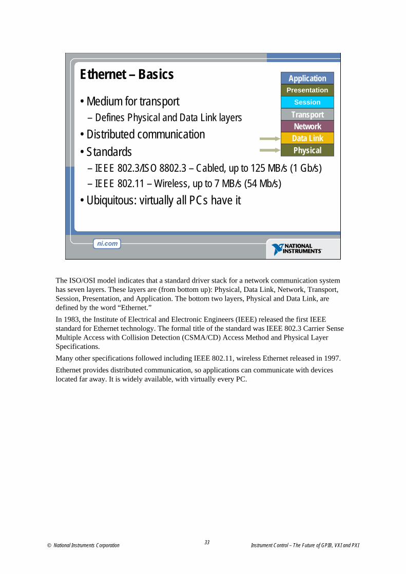
• Medium for transport– Defines Physical and Data Link layers
• Distributed communication• Standards
– IEEE 802.3/ISO 8802.3 – Cabled, up to 125 MB/s (1 Gb/s)– IEEE 802.11 – Wireless, up to 7 MB/s (54 Mb/s)
• Ubiquitous: virtually all PCs have it
Presentation
PhysicalData LinkNetwork
Transport
Application
Session
The ISO/OSI model indicates that a standard driver stack for a network communication system has seven layers. These layers are (from bottom up): Physical, Data Link, Network, Transport, Session, Presentation, and Application. The bottom two layers, Physical and Data Link, are defined by the word “Ethernet.” In 1983, the Institute of Electrical and Electronic Engineers (IEEE) released the first IEEE standard for Ethernet technology. The formal title of the standard was IEEE 802.3 Carrier Sense Multiple Access with Collision Detection (CSMA/CD) Access Method and Physical Layer Specifications. Many other specifications followed including IEEE 802.11, wireless Ethernet released in 1997.Ethernet provides distributed communication, so applications can communicate with devices located far away. It is widely available, with virtually every PC.
© National Instruments Corporation Instrument Control – The Future of GPIB, VXI and PXI
34
Ethernet – Wireless
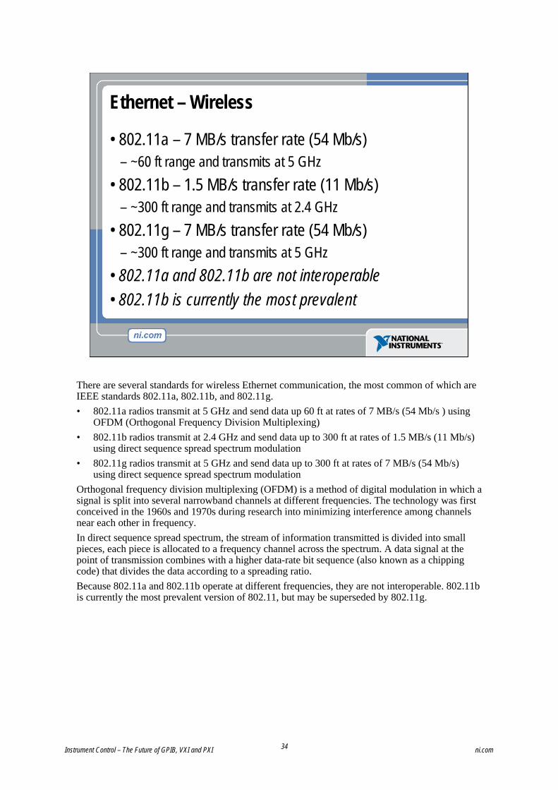
• 802.11a – 7 MB/s transfer rate (54 Mb/s)– ~60 ft range and transmits at 5 GHz
• 802.11b – 1.5 MB/s transfer rate (11 Mb/s)– ~300 ft range and transmits at 2.4 GHz
• 802.11g – 7 MB/s transfer rate (54 Mb/s)– ~300 ft range and transmits at 5 GHz
• 802.11a and 802.11b are not interoperable• 802.11b is currently the most prevalent
There are several standards for wireless Ethernet communication, the most common of which are IEEE standards 802.11a, 802.11b, and 802.11g.• 802.11a radios transmit at 5 GHz and send data up 60 ft at rates of 7 MB/s (54 Mb/s ) using
OFDM (Orthogonal Frequency Division Multiplexing)• 802.11b radios transmit at 2.4 GHz and send data up to 300 ft at rates of 1.5 MB/s (11 Mb/s)
using direct sequence spread spectrum modulation • 802.11g radios transmit at 5 GHz and send data up to 300 ft at rates of 7 MB/s (54 Mb/s)
using direct sequence spread spectrum modulationOrthogonal frequency division multiplexing (OFDM) is a method of digital modulation in which a signal is split into several narrowband channels at different frequencies. The technology was first conceived in the 1960s and 1970s during research into minimizing interference among channels near each other in frequency.In direct sequence spread spectrum, the stream of information transmitted is divided into small pieces, each piece is allocated to a frequency channel across the spectrum. A data signal at the point of transmission combines with a higher data-rate bit sequence (also known as a chipping code) that divides the data according to a spreading ratio.Because 802.11a and 802.11b operate at different frequencies, they are not interoperable. 802.11b is currently the most prevalent version of 802.11, but may be superseded by 802.11g.
Instrument Control – The Future of GPIB, VXI and PXI ni.com
35
Ethernet – Test and Measurement Protocol Basics
• TCP/IP Instrument Protocol Specification– Known as VXI-11 though not related to VXI– Defined by VXI Consortium because of member interest
• What is it?– “GPIB over Ethernet”– Test and Measurement standard since 1995– Follows the IEEE 488.2 device model – Handles device locking for multiple controllers
The Test and Measurement industry standardized VXI-11 in 1995. While VXI-11 was standardized through the VXI Consortium because of member interest, it does not relate to VXI.The base VXI-11 standard defines the packets that are sent to the network instrument. VXI-11 defines three subclasses. The most common subclass is defined in the VXI-11.3 subclass. This defines a native network instrument that follows the IEEE 488.2 device model. These instruments act like existing IEEE 488.2 GPIB instruments and are generally referred to as “GPIB over Ethernet.” As a side note, other VXI-11 subclasses are VXI-11.1 and VXI-11-2.• VXI-11.1 defines a converter between Ethernet and VXI• VXI-11.2 defines a converter between Ethernet and GPIBBoth of these subclasses are primarily used in bridge products. VXI-11 defines a model for device locking, so that multiple controllers can communicate to the same instrument without sacrificing reliability. Normally, the controller locks the instrument, performs a set of “atomic” operations, and then unlocks the instrument. This allows unrestricted access to the instrument and promotes sharing.
© National Instruments Corporation Instrument Control – The Future of GPIB, VXI and PXI
36
VXI-11 – Communication
• Uses remote procedure calls (RPC) over TCP/IP• Defines standard packet formats for read, write,
trigger, status byte, and so on• Channel-based
– Core – Abort – Interrupt
VXI-11 supports any network that uses the Internet Protocol suite (including TCP/IP). It communicates by creating packets for standard commands and transmitting them across TCP using the ONC/RPC protocol. TCP was chosen because it ensures the correct ordering of messages, guarantees arrival of messages, allows parameters of a remote procedure to be of any size, and provides awareness of both connections and terminations of connections. VXI-11 defines standard packets for all Test and Measurement commands, including data transfers, triggers, clears, and status byte requests. It also includes support for remote/local, device locking, and service requests.Communication in VXI-11 is channel based. Three channels are defined: Core, Abort, and Interrupt. • The Core channel is used to transfer all requests except device_abort, and device_intr_srq.• The Abort channel is used to transfer the device_abort request. This provides a mechanism to
cancel a transfer that is currently in progress on the Core channel.• The Interrupt channel is used to transfer the device_intr_srq request. This provides a
mechanism for the device to request service from the host.In VXI-11, a host first establishes a connection with a device. The host then sends and receives data using formats defined by the VXI-11 specification.
Instrument Control – The Future of GPIB, VXI and PXI ni.com
37
Ethernet for Test and Measurement
• Pros– Long distance to instruments – OS independent– NI-VISA support preserves instrument driver investment
• Cons– Supported by very few instruments– Non-deterministic– May require advanced network administration– Security issues if used on external Internet
There are many advantages to Ethernet and to networking in general, some of which apply in the context of instrument control. These include the ability to distribute measurement systems essentially eliminating any distance restrictions, it is operating system independent, and support through NI-VISA allows users to preserve their investment in instrument drivers and test applications.The drawbacks of Ethernet for instrument control include the fact that it is currently supported on very few instruments, it is non-deterministic, and if it is used on an actual network (not an internal closed network) it may require advanced network administration and corporate IT departments and has issues with security.
© National Instruments Corporation Instrument Control – The Future of GPIB, VXI and PXI
38
USB – Basics
Node
Hub
Hub
Hub
Node Node
Node
Hub
HostRoot Hub
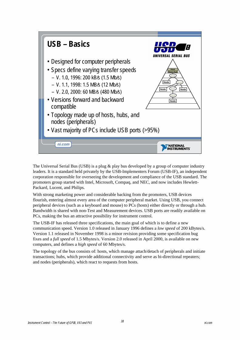
• Designed for computer peripherals• Specs define varying transfer speeds
– V. 1.0, 1996: 200 kB/s (1.5 Mb/s)– V. 1.1, 1998: 1.5 MB/s (12 Mb/s)– V. 2.0, 2000: 60 MB/s (480 Mb/s)
• Versions forward and backward compatible
• Topology made up of hosts, hubs, and nodes (peripherals)
• Vast majority of PCs include USB ports (>95%)
The Universal Serial Bus (USB) is a plug & play bus developed by a group of computer industry leaders. It is a standard held privately by the USB-Implementers Forum (USB-IF), an independent corporation responsible for overseeing the development and compliance of the USB standard. The promoters group started with Intel, Microsoft, Compaq, and NEC, and now includes Hewlett-Packard, Lucent, and Philips. With strong marketing power and considerable backing from the promoters, USB devices flourish, entering almost every area of the computer peripheral market. Using USB, you connect peripheral devices (such as a keyboard and mouse) to PCs (hosts) either directly or through a hub. Bandwidth is shared with non-Test and Measurement devices. USB ports are readily available onPCs, making the bus an attractive possibility for instrument control.The USB-IF has released three specifications, the main goal of which is to define a new communication speed. Version 1.0 released in January 1996 defines a low speed of 200 kBytes/s. Version 1.1 released in November 1998 is a minor revision providing some specification bug fixes and a full speed of 1.5 Mbytes/s. Version 2.0 released in April 2000, is available on new computers, and defines a high speed of 60 Mbytes/s.The topology of the bus consists of: hosts, which manage attach/detach of peripherals and initiate transactions; hubs, which provide additional connectivity and serve as bi-directional repeaters; and nodes (peripherals), which react to requests from hosts.
Instrument Control – The Future of GPIB, VXI and PXI ni.com
39
USB – Test and Measurement Protocol Basics
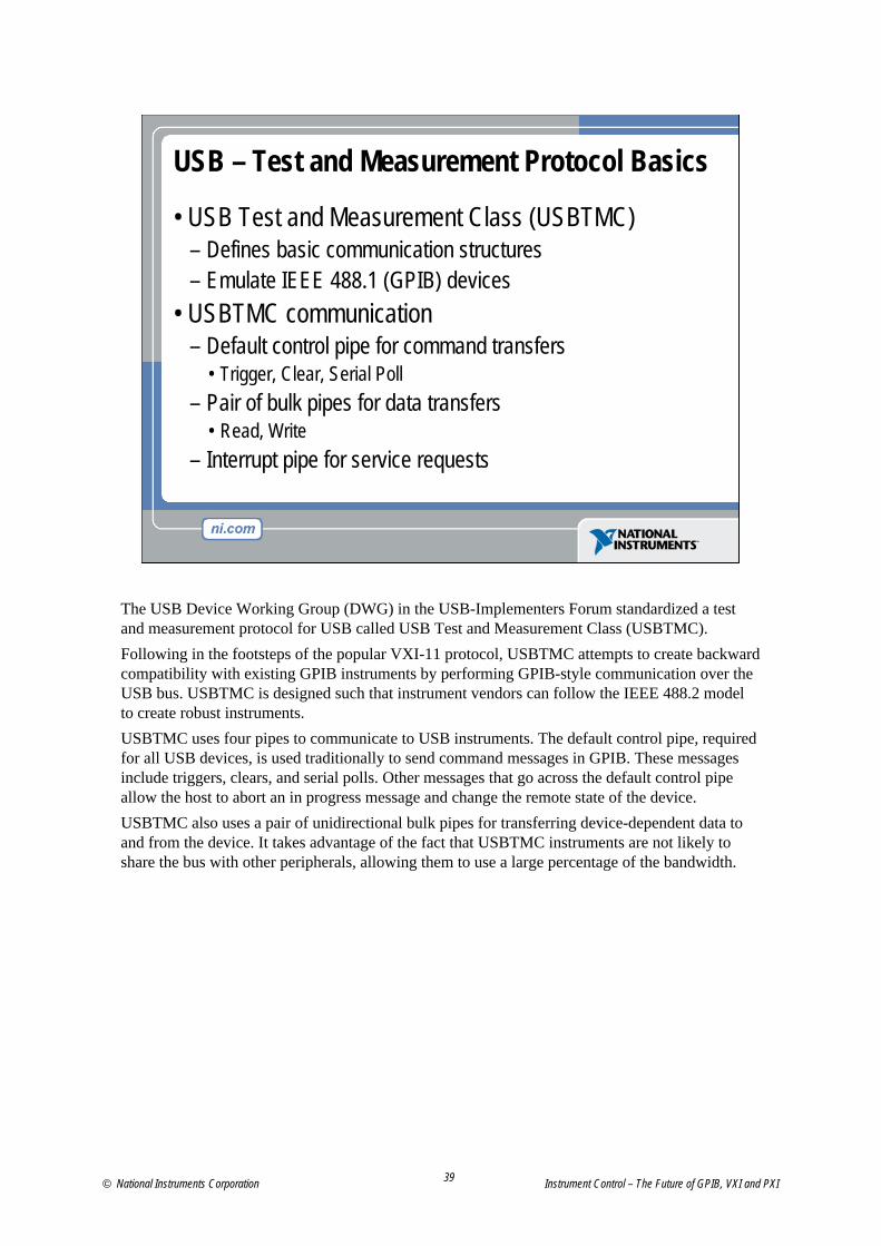
• USB Test and Measurement Class (USBTMC)– Defines basic communication structures– Emulate IEEE 488.1 (GPIB) devices
• USBTMC communication– Default control pipe for command transfers
• Trigger, Clear, Serial Poll– Pair of bulk pipes for data transfers
• Read, Write– Interrupt pipe for service requests
The USB Device Working Group (DWG) in the USB-Implementers Forum standardized a test and measurement protocol for USB called USB Test and Measurement Class (USBTMC).Following in the footsteps of the popular VXI-11 protocol, USBTMC attempts to create backward compatibility with existing GPIB instruments by performing GPIB-style communication over the USB bus. USBTMC is designed such that instrument vendors can follow the IEEE 488.2 model to create robust instruments. USBTMC uses four pipes to communicate to USB instruments. The default control pipe, required for all USB devices, is used traditionally to send command messages in GPIB. These messages include triggers, clears, and serial polls. Other messages that go across the default control pipe allow the host to abort an in progress message and change the remote state of the device. USBTMC also uses a pair of unidirectional bulk pipes for transferring device-dependent data to and from the device. It takes advantage of the fact that USBTMC instruments are not likely to share the bus with other peripherals, allowing them to use a large percentage of the bandwidth.
© National Instruments Corporation Instrument Control – The Future of GPIB, VXI and PXI
40
USB for T&M
• Pros– Connectors on almost all desktop computers – Plug & play, including hot plug– Preserves firmware investment– NI-VISA support can preserve instrument driver investment
• Cons– Supported by very few instruments– Consumer connectors (no screws) – Minimal trigger support– Relatively long latencies
USB offers many advantages when considered for Test and Measurement applications. It is available on almost all desktop and laptop computers and it is plug & play and hot plug capable, making it easy to use. Because of the USBTMC protocol, instrument manufacturers can preserve their investment in firmware and VISA support, and this allows users to preserve their investment in instrument drivers and test software.The disadvantages of USB are that it is currently supported by few instruments, it provides only consumer connectors making it unsuitable for harsh industrial environments, provides minimal trigger support and because it is a serial bus, it has relatively long data and command transfer latencies.
Instrument Control – The Future of GPIB, VXI and PXI ni.com

41
1394 – Basics
• IEEE 1394 Standard– Also known as FireWire
• Serial bus– High throughput (100MB/s
or 800 Mb/s) / long latency• Peer-to-peer• Used mainly in digital
photography and videos
• Isochronous– Guaranteed bandwidth– Packets with errors are
unrecoverable• Asynchronous
– Bandwidth not guaranteed– Bad packets can be retried
IEEE 1394, also known as FireWire, is a high-performance serial bus developed by Apple Computer, Inc., in the early 1990s. Although Microsoft Windows operating systems support FireWire, Intel PC peripheral chip sets do not currently include it, so in most cases you need an IEEE 1394 controller for your PC.IEEE 1394 provides a peer-to-peer high speed serial bus capable of throughputs up to 800 megabits/s or approximately 100 megabytes/s. It is mainly used in digital photography and videos.IEEE 1394 provides two modes of transfer: an isochronous mode which guarantees bandwidth but cannot retry packets with errors, and an asynchronous mode where bandwidth is not guaranteed but bad packets can be retried ensuring data integrity.
© National Instruments Corporation Instrument Control – The Future of GPIB, VXI and PXI
42
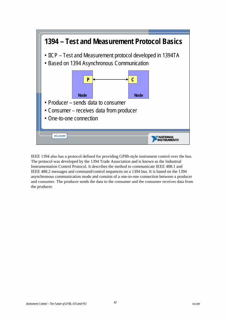
• IICP – Test and Measurement protocol developed in 1394TA• Based on 1394 Asynchronous Communication
• Producer – sends data to consumer• Consumer – receives data from producer• One-to-one connection
Node
1394 – Test and Measurement Protocol Basics
P
Node
C
IEEE 1394 also has a protocol defined for providing GPIB-style instrument control over the bus. The protocol was developed by the 1394 Trade Association and is known as the Industrial Instrumentation Control Protocol. It describes the method to communicate IEEE 488.1 and IEEE 488.2 messages and command/control sequences on a 1394 bus. It is based on the 1394 asynchronous communication mode and consists of a one-to-one connection between a producer and consumer. The producer sends the data to the consumer and the consumer receives data from the producer.
Instrument Control – The Future of GPIB, VXI and PXI ni.com
43
1394 for Test and Measurement
• Pros– Flexible physical topology– High throughput
• Cons– Lack of industry support
• Not many PCs (<10%), or instruments (~0%) support it– Test and Measurement extensions complicated– Relatively long latencies
IEEE 1394 offers a few benefits for instrument control including a flexible physical topology and high throughput which has the potential of providing a faster communication link to instruments.However, the bus also has several drawbacks, the largest of which is the lack of industry support. Very few PCs come standard with IEEE 1394 buses and almost no instruments provide the bus as an instrument control option. In addition the Test and Measurement protocol and extensions for 1394 are fairly complicated and result in relatively long data and command transfer latencies.
© National Instruments Corporation Instrument Control – The Future of GPIB, VXI and PXI
44
Stand-Alone Instrument Bus Comparison
HighHighHighLow/ MediumLowLatency (First Byte and Service Request)
<10<100<100>10,000>10,000Product Availability
100 MB/s60 MB/s125 MB/s28.8 kB/s1.5 MB/s8 MB/s (HS488)
Maximum Throughput
Minimal
Consumer
30m
127
USB
Minimal
Consumer
4.5m
63
IEEE 1394
MinimalMinimalMinimalTriggering
ConsumerIndustrial/ ConsumerIndustrialConnectors
No Limit (300ft Wireless)15m20mMax Cable Length
No Limit114Maximum Number of Devices
EthernetRS-232GPIB
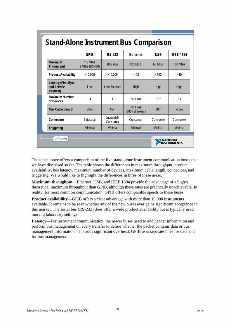
The table above offers a comparison of the five stand-alone instrument communication buses that we have discussed so far. The table shows the differences in maximum throughput, product availability, bus latency, maximum number of devices, maximum cable length, connectors, and triggering. We would like to highlight the differences in three of these areas.Maximum throughput—Ethernet, USB, and IEEE 1394 provide the advantage of a higher theoretical maximum throughput than GPIB, although these rates are practically unachievable. In reality, for most common communication, GPIB offers comparable speeds to these buses.Product availability—GPIB offers a clear advantage with more than 10,000 instruments available. It remains to be seen whether any of the new buses ever gains significant acceptance in this market. The serial bus (RS-232) does offer a wide product availability but is typically used more in laboratory settings.Latency—For instrument communication, the newer buses need to add header information and perform bus management on every transfer to define whether the packet contains data or bus management information. This adds significant overhead. GPIB uses separate lines for data and for bus management.
Instrument Control – The Future of GPIB, VXI and PXI ni.com
45
RS-232
GPIB
Proliferation of Network Technology
1990
Ethernet 10 Mbps
Gen
eral
Pu
rpos
eIn
dust
rial
Aut
omot
ive
ASI
ARCNETBACNet
Bluetooth
BITBUS
CAN
CEBusDeviceNet
Ethernet 100 Mbps
GigabitENET
FOUNDATIONFieldbus
FIP
FlexRay
HART
HomeRF
HPNAIEEE 802.11
IEEE 1394SPI
Interbus
J1850LIN
LonWorks
Microwire
Modbus
Modbus/TCP
Ethernet/IP
ProfiNetOptomux
Profibus - DP
Profibus - PARS-485
SERCOS SDS
Seriplex
TTP
USB
WorldFIP
X10I2C
CANOpen
ControlNet
HSESP50
Remote I/O
1980 2000
MOST
D2BJ1939VAN
Fibre ChannelToken Ring
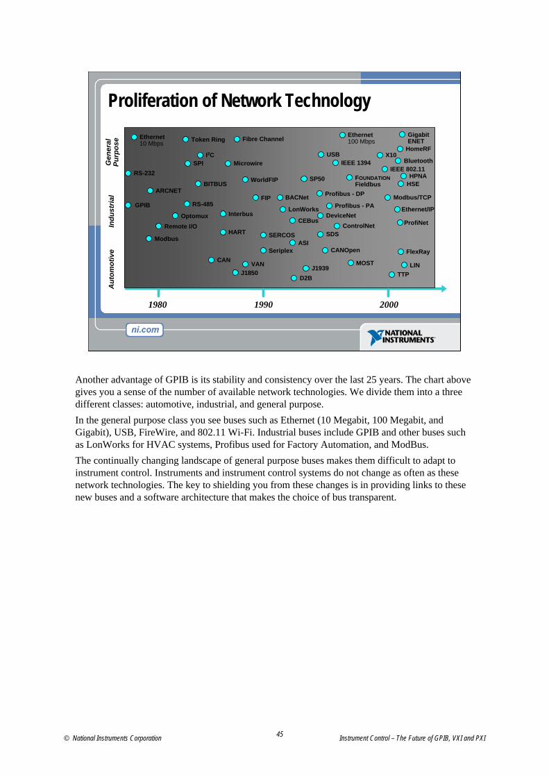
Another advantage of GPIB is its stability and consistency over the last 25 years. The chart above gives you a sense of the number of available network technologies. We divide them into a three different classes: automotive, industrial, and general purpose.In the general purpose class you see buses such as Ethernet (10 Megabit, 100 Megabit, and Gigabit), USB, FireWire, and 802.11 Wi-Fi. Industrial buses include GPIB and other buses such as LonWorks for HVAC systems, Profibus used for Factory Automation, and ModBus.The continually changing landscape of general purpose buses makes them difficult to adapt to instrument control. Instruments and instrument control systems do not change as often as these network technologies. The key to shielding you from these changes is in providing links to these new buses and a software architecture that makes the choice of bus transparent.
© National Instruments Corporation Instrument Control – The Future of GPIB, VXI and PXI
46
Industry Trends for Stand-Alone Buses
• GPIB still most popular instrument control bus– Robust, proven technology– Extremely large install base
• Other buses being considered for instrument control– Ethernet, USB, IEEE-1394
• Most likely short-medium term outlook– Mixed and hybrid systems including GPIB and other buses
• Software is key for shielding user from bus changes
Now that we have discussed all the major stand-alone buses, we can look at the trends in the test and measurement industry for using these buses for instrument control.GPIB is still by far the most popular bus for instrument control. This is in large part because of the extremely large installed base of GPIB instruments and because GPIB is a robust and proven technology specifically designed for instrument control.Other buses such as Ethernet, USB, and IEEE 1394 are being considered for applications in instrument control because of their wide availability in new computers and their high performance. These buses, however, were not designed for instrument control and they have some disadvantages when used in this area.The most likely outlook in the short to medium term is for the creation of mixed I/O and hybrid systems that combine these new buses with GPIB instruments to get the best of both worlds. The key to making this scenario as seamless as possible lies in the software. Using a common software architecture that integrates all these buses makes it inconsequential which bus you communicate with.
Instrument Control – The Future of GPIB, VXI and PXI ni.com
47
GPIB Bridges: From Any Bus to GPIB Instruments
• Connect to your GPIB instrument from:– USB, Ethernet, IEEE 1394, and more
• Completely software transparent– Maintain software and hardware investments– Take advantage of new bus technologies
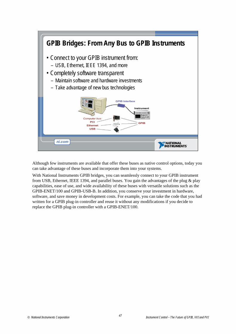
Although few instruments are available that offer these buses as native control options, today you can take advantage of these buses and incorporate them into your systems.With National Instruments GPIB bridges, you can seamlessly connect to your GPIB instrument from USB, Ethernet, IEEE 1394, and parallel buses. You gain the advantages of the plug & play capabilities, ease of use, and wide availability of these buses with versatile solutions such as the GPIB-ENET/100 and GPIB-USB-B. In addition, you conserve your investment in hardware, software, and save money in development costs. For example, you can take the code that you had written for a GPIB plug-in controller and reuse it without any modifications if you decide to replace the GPIB plug-in controller with a GPIB-ENET/100.
© National Instruments Corporation Instrument Control – The Future of GPIB, VXI and PXI

48
Measurement Hardware: Modular Instruments
Measurement Hardware
Instrument Control Buses
• PCI bus• VXI bus• PXI
We now discuss modular instruments, which combine the measurement hardware and the instrument control bus into one device.
© National Instruments Corporation Instrument Control – The Future of GPIB, VXI and PXI

49
Modular versus Stand-Alone InstrumentsModular Instruments • Open/multi-vendor• User-defined • Easy integration• Scalable• Standard SW model• Pay for what you need
Stand-Alone Instruments• Closed/proprietary• Vendor-defined • Limited integration• Limited expandability• Proprietary SW model• Pay for what you get
Modular InstrumentsModular instruments empower you, the user, to define exactly what you need in your system, while at the same time allowing for future expansion. It provides a standard software model across multiple types of measurement and control devices enabling a high degree of integration and productivity. In modular systems, you only pay for what you need because you define the system.Stand-Alone InstrumentsStand-alone instruments typically are closed and all the functionality is defined by the vendor. This often results in the user paying for features not required. Additionally, stand-alone instruments are not inherently made to integrate into automated test systems, and thus present challenges in integration and automation. Furthermore, using stand-alone instruments considerably reduces the possibility to expand test systems in the future—often requiring a complete rework just to add small amounts of capability.Ideally, automated test platforms are based on a modular platform with the ability to add specialized stand-alone instruments when needed.
Instrument Control – The Future of GPIB, VXI and PXI ni.com

50
Modular Instruments Benefits
• Increased measurement throughput– Faster data transfer– Better instrument synchronization– Tighter software and hardware integration
• Smaller footprint• Lower cost
Modular
Stand-Alone
With modular instruments, you retain instrument-quality measurements while taking advantage of the flexibility and performance of your laptop or desktop PC. Computer-based modular instruments deliver:• Increased measurement throughput—Reduces the amount of time required to test your
product by reducing the time it takes to make critical measurements. The primary components of measurement speed include:– Faster data transfer, which you can achieve by leveraging the132 MB/s throughput of the
PCI or PXI bus and memory-mapped I/O structure to transfer measurements to your computer at rates 10 to 300 times faster than traditional stand-alone instruments
– Better instrument synchronization, made possible in modular instrumentation through integrated timing and triggering buses directly on the backplane of the measurement system
– Software integration, with LabVIEW, LabWindows/CVI, Visual C/C++, and Visual Basic
• Smaller footprint—Save space and money both in your lab and factory floor by integrating your equipment inside the computer or with PXI.
• Lower cost—You pay only for the functionality you need, and you also get increased cost savings with less development time and easier deployment of systems built using modular instrumentation.
© National Instruments Corporation Instrument Control – The Future of GPIB, VXI and PXI

51
Data Transfer
Modular Instruments Reduce Measurement Time
Meas
urem
ent P
erfor
manc
e
PC Integration
PCI/PXIVXIGPIB
Digitizer Conversion
Data Analysis
Modular instruments improve overall system performance by reducing the time required to take measurements. Digitizer Conversion—The amount of time required to digitize a signal acts independently of the instrumentation platform. Regardless of whether the conversion takes place in a stand-alone instrument or on a modular instrument, the sample rate and number of data points ultimately determine the digitizer conversion time.Data Analysis—In many measurement systems, data analysis is performed in the stand-alone instrument, whereas in other systems, analysis occurs primarily on the PC. Although a trend in industry has dictated putting standard PC architectures inside traditional instruments, instrument vendors cannot match the rapid performance increases of the PC industry. Therefore, measurement systems that perform their analysis using the latest PC technologies will benefit from increased processing power and will lower the time required to perform signal analysis.Data Transfer— For users making automated measurements, the major benefit of modular instruments is the improved data transfer rate. By leveraging the 132 MB/s and memory-mapped I/O structure of the PCI bus to transfer measurements to your computer, you can significantly reduce overall measurement time.
Instrument Control – The Future of GPIB, VXI and PXI ni.com

52
PCI Bus – Basics• Industry standard computer bus• Unified computer makers (IBM, Apple, Sun, etc.)• Robust electrical specification• Flexible mechanical specification
– PCI– CardBus– CompactPCI– PXI
• Register-based
The PCI bus is an industry-standard computer bus used for expansion of desktop computers. Users typically plug PCI expansion boards into PCI slots in their computers to add functionality ranging from modems and video capture devices to instrument control and data acquisition cards.The PCI bus’ strengths are that it unified computer manufacturers over one standard, it defines a robust electrical specification, and it defines flexible mechanical specification that has been leveraged in other form factors. The PCI bus is also register based, providing much higher communication throughputs.
© National Instruments Corporation Instrument Control – The Future of GPIB, VXI and PXI

53
VXI Bus – Basics• Based on Versa Module Eurocard (VME) backplane• IEEE 1155• First attempt at multi-vendor standard• Goals
– Increased interchangeability– Decreased size– Increased system throughput– Lower cost
• 80% of instruments message based
The VME eXtensions for Instrumentation or VXI bus was the first attempt at a multi-vendor industry standard specific to instrumentation. As the name implies, VXI builds on the VME bus and is based on the VME backplane. It was defined in 1987 and later standardized as the IEEE 1155 standard. Its goals included increased interchangeability, decreased size, increased system throughput and lower cost. VXI retained the GPIB communication methodology and more than 80% of VXI instruments use message-based communication.
Instrument Control – The Future of GPIB, VXI and PXI ni.com

54
VXI Bus
• Accomplishments– Physical size reduction—smaller systems– More precise timing and synchronization– Interoperability between manufacturers
• Shortcomings– No software standard, same issues as GPIB– Did not leverage commercial PC technologies
• No reduced system costs• No widespread adoption• Lacking in ease of use
The VXI bus did have major accomplishments in achieving some of its goals. Although still bulky, VXI systems did achieve a reduction in physical size. VXI also achieved better interoperability between vendors and defined an electrical specification that provides more precise timing and synchronization.The VXI bus did have some shortcomings, however. VXI did not adopt a software standard. The goal of increased system throughput was never fully realized because, in order to make programming manageable, most VXI instruments are message based. Therefore, the speed of GPIB and VXI for normal communication is very similar. In addition, VXI did not leverage standard commercial PC technologies, so it failed to achieve its goal of reduced system cost, it is lacking in ease of use, and never achieved widespread adoption.
© National Instruments Corporation Instrument Control – The Future of GPIB, VXI and PXI

55
PXI Combines Standard Technologies
bus CompactPCICompactPCompactPCICI
PCIPPCICI
The major strength of PXI is that it uses proven industry-standard technology. PXI is built on CompactPCI, an industrial version of the PCI bus found in almost all desktop computers. On top of CompactPCI, PXI adds timing, triggering, and synchronization similar to functionality delivered in VXI. For easy integration, PXI uses driver and networking standards from the PC software market, including plug-and-play drivers.Because PXI and CompactPCI are completely interoperable, users can use any core CompactPCI product in a PXI system and vice-versa.
Advances in LabVIEW and PXI Instrumentation Seminar ni.com

56
PXI Timing and SynchronizationPXI timing and synchronization improves performance
Star TriggerSy
stem
Cont
rolle
r
Perip
hera
l
10 MHzCLK
133 MB/s, 33 MHz, 32-bit Computer BusPe
riphe
ral
Perip
hera
l
Local BusSt
ar T
rigge
rCo
ntro
ller
PXI Trigger Bus
Electrically, PXI adds a trigger bus (eight lines), a star trigger (13 slot-specific signals), a 10 MHz reference clock (equally distributed), and local buses (13 lines wide). The star trigger control functionality is separated from the main system controller to allow using standard CompactPCI controllers and to require users to pay for the star trigger feature only if they need it.• System Reference Clock—A highly accurate 10 MHz clock is independently
distributed to each PXI peripheral slot through equal-length traces. Multiple cards can use this common time base for synchronization of events.
• Trigger Bus—Eight bused trigger lines link all PXI slots in a bus segment so that multiple boards can interact and control each other’s events through hardware.
• Star Trigger—A special star trigger slot is defined that provides an independent dedicated line for each of up to 13 peripheral slots on a single backplane. When a star trigger controller is plugged into this slot, it can be used to control, monitor, or route triggers among peripheral slots with very low skew (within 1 nanosecond).
• Local Bus—A right and left local bus composed of 13 lines is available to each peripheral slot for private communication between adjacent slots. Pairs of peripherals can pass analog or digital signals back and forth using the local bus.
© National Instruments Corporation Advances in LabVIEW and PXI Instrumentation Seminar

57
The Governing Body of PXI
• Charter- Promote PXI- Ensure interoperability- Control the PXI Specification
• Focused on user success in measurement and automation• More than 50 member companies
www.pxisa.org
Systems Alliance
The PXI specification is controlled by the PXI Systems Alliance—a group of more than 60 companies determined to ensure end-user success. The PXI Systems Alliance was formed around a charter document that defines the goals of the organization, which include:• Promoting PXI and CompactPCI for measurement and automation• Maintaining and revision control of the PXI specification• Ensuring the highest levels of multi-vendor interoperability at the mechanical,
electrical, and software levelsThe PXI Systems Alliance Web site contains:• White papers• Free softcopy of the PXI specification• List of all members• Upcoming event information• Product directory arranged by category
Advances in LabVIEW and PXI Instrumentation Seminar ni.com

58
PXI Systems Alliance MembersEXFOERNIGageGespac
Goepel ElectronicGDE Systems (Marconi)GTE-ERSInnovative IntegrationJTAGKineticSystemsLeCroyMAC Panel
Acqiris Advanced Power DesignsAdvanced Test MethodsAlphi TechnologyAMPAnalogicASCORARVOO EngineeringATEMEA&T Engineering Tech. Ctr.B&B TechnologiesBallard TechnologyBittWare Research SystemsBode EnterprisesBRIMEC&H TechnologiesCHROMA ATEData PatternsDateppliDatumDolch Computer Systems
Marek MicroMEN Mikro ElektronikNational InstrumentsPickering InterfacesPX Instrument Tech.Racal InstrumentsRohde and SchwarzQuantum ControlsSBS GreenSpringSchroffShaanxi HiTech SignametricsSRCTestWareTracewell SystemsTTI TestronVero Electronics (APW)Viewpoint SystemsVirginia Panel Corp.ZYNX
PXI Systems Alliance members include instrument suppliers, platform suppliers (chassis/controllers), component suppliers, and system integrators. For more information on the alliance and links to member companies, refer to www.pxisa.org.PXISA Members who provide System Integrator Services: Advanced Test Methods (UK), ATEME (France), A&T Engineering Technology Center (USA), Bloomy Controls (USA), Bode Enterprises (USA), BRIME (France), B&B Technologies (USA), Cortest(USA), C&H Technologies (USA), Data Patterns (India), Dateppli (USA), GenRad (International), Geotest, GTE Electronic Repair Service (USA), Marconi Integrated Systems (USA), MarekMicro (Germany), Quantum Controls (USA), Racal Instruments, Shaanxi Hitech Electronic (China)
© National Instruments Corporation Advances in LabVIEW and PXI Instrumentation Seminar

59
PXI Module Availability
MODULAR INSTRUMENTSOscilloscopes/Digitizers
DMMsArbitrary Waveform Generators
RF InstrumentsDigital I/O
Dynamic Signal Analysis
DAQ AND CONTROLMultifunction I/O
Digital I/OAnalog OutputCounter/TimersReal-time I/O
MOTION/VISIONAnalog/Digital Image Acquisition
Stepper/Servo Motion Control
PERIPHERALSPrototyping Boards
Hard DrivesPC Card Carriers
M-module Carriers
BUS INTERFACESGPIB
EthernetDeviceNet
CANARINC/MIL-STD-1553
SCSIPROCESS TESTBoundary Scan
1,000 Products from More than 50 Vendors
PXI offers a wide variety of modules from National Instruments and many other companies. Whether your application is in test, measurement, data acquisition, or industrial automation, you can choose modules to meet your application’s specific requirements. Instrumentation, data acquisition, motion control, image acquisition, and industrial communications modules are available, as well as interfaces to other buses such as PCMCIA, SCSI, Ethernet, RS-232, RS-485, CAN, VXI, VME, and GPIB.
Advances in LabVIEW and PXI Instrumentation Seminar ni.com

60
Select Your Control Scheme
• Embedded controllers– Most compact solution– Modular = easy maintenance– Pentium III class
• Remote MXI-3 controllers– Short or long distance – Fully transparent– Low cost
Choose whether you want to control your system from a standard PC with MXI-3 or with a fully integrated embedded computer. If your application precludes the use of an external PC and you require a completely integrated, compact solution, then an embedded computer is the right choice. An embedded computer is required for controlling portable chassis with integrated displays. National Instruments offers a variety of embedded computers with your choice of processor speed, I/O configuration, operating system, and application development software. All embedded computers include a built-in hard drive, floppy drive, and video. Peripheral ports such as USB, serial, parallel, mouse, and keyboard are also standard. GPIB and Ethernet ports are also available as options on some embedded computers.MXI-3 kits give you a fully transparent link from your PC to your PXI system. You plug a MXI-3 interface card into your PC and connect it with a copper or fiber optic cable to a MXI-3 module in slot 1 of your PXI system. MXI-3 extends the PCI bus at full speed so that the processor in your PC transparently configures and controls the PXI modules—whether the PXI system is 2 m or 200 m away. MXI-3 is a low cost control solution that allows you to benefit from the very latest in PC technology.
© National Instruments Corporation Advances in LabVIEW and PXI Instrumentation Seminar

61
Modular Test System Architecture
Advances in LabVIEW and PXI Instrumentation Seminar ni.com

62
Audio/Video Modulator System
The heart of today’s seminar is to show you a series of modular instruments in PXI and demonstrate how you can use these products in conjunction with each other. This system tests two consumer electronic products, an audio D/A converter from Texas Instruments and a consumer audio/video modulator. We stimulate the audio DAC with a pattern from a digital I/O board and analyze the audio output with a dynamic signal analyzer. The audio is then fed into the modulator along with a video pattern generated from an NI arbitrary waveform generator, which is in turn analyzed using a high-speed NI digitizer. The A/V modulator takes these two inputs and modulates them onto separate high-frequency carriers. We view the resulting RF spectrum with the new NI PXI-5660 2.7 GHz RF signal analyzer and use this product, along with LabVIEW software tools, to perform demodulation and extract the original audio and video signals. We also use the new NI PXI-4070 6½-digit FlexDMM to monitor the power supply to both devices under test.
© National Instruments Corporation Advances in LabVIEW and PXI Instrumentation Seminar

63
LabVIEW
PXI Chassis
PXI Trigger Bus
High
-Spe
ed
Digi
tal I/
O
Audio Stimulus- Response
AudioDAC
Soun
d an
dVi
brat
ion
Audio/Video Modulator System
RF S
igna
lAn
alyze
r
Flex
DMM
Switc
h
Arbi
trary
Wfm
Gen
High
-Spe
edDi
gitiz
er
Audio/VideoModulator
Powe
r Su
pply
PowerMeasurements
VideoGeneration
RFDemod
Here is a graphical illustration of the test system just described. As you can see, we use a wide range of PXI modular instrumentation. As we see throughout this seminar, the LabVIEW program performs several key functions, including stimulus-response measurements of the audio and video signals, a variety of power measurements, and software demodulation.
Advances in LabVIEW and PXI Instrumentation Seminar ni.com