Presentation Outline - National Energy Technology … Library/Research/Coal/Advanced... ·...
22
Transcript of Presentation Outline - National Energy Technology … Library/Research/Coal/Advanced... ·...


Presentation Outline
• Introduction– The problem– The solution– Relevance– The team
• Award Details– Contract details– Program objectives– Work breakdown structure– Schedule and milestones– Project management plan
• Conclusion
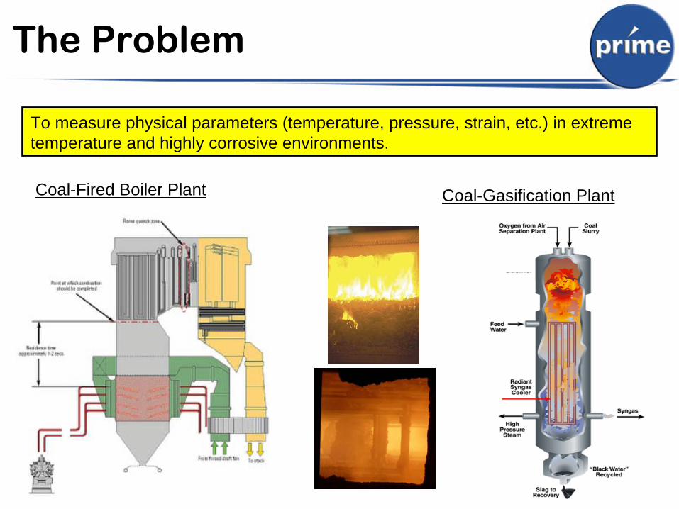
The Problem
To measure physical parameters (temperature, pressure, strain, etc.) in extreme temperature and highly corrosive environments.
Coal-Fired Boiler Plant Coal-Gasification Plant
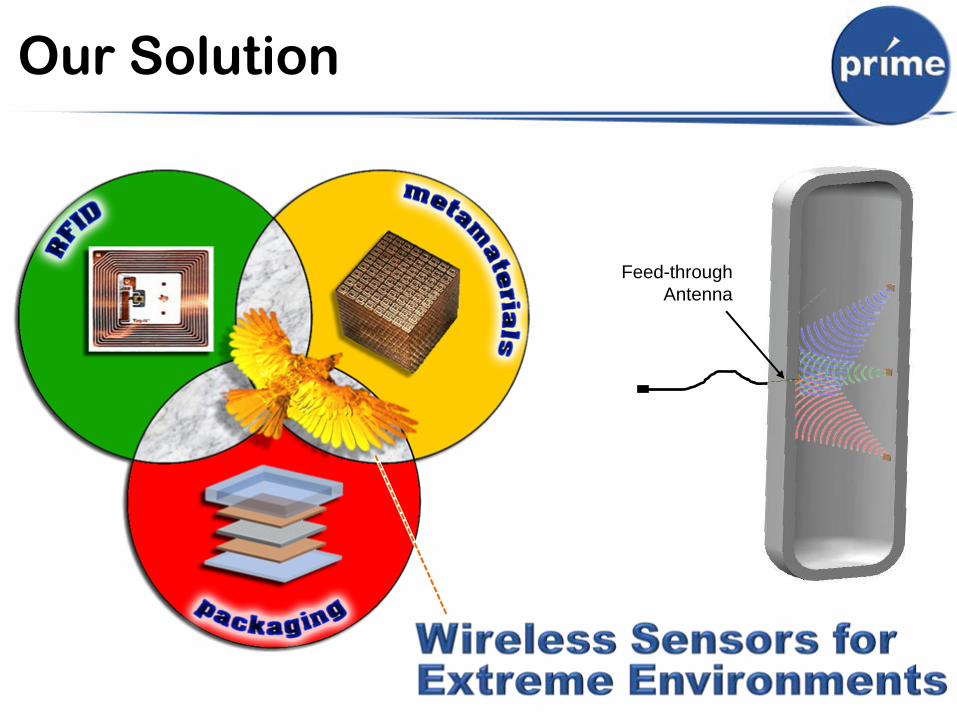
Our Solution
Feed-throughAntenna
Benefits of Wireless
• No cables connecting to sensors• Enhanced reliability• Greater freedom placing sensors• Simplified installations• Easier multiplexing of
multiple sensors• Fully encapsulated• Longer operational lifetime
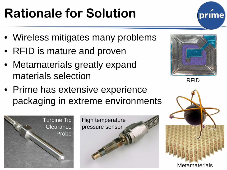
Rationale for Solution
• Wireless mitigates many problems• RFID is mature and proven• Metamaterials greatly expand
materials selection• Príme has extensive experience
packaging in extreme environments
Turbine Tip Clearance
Probe
High temperature pressure sensor
Metamaterials
RFID
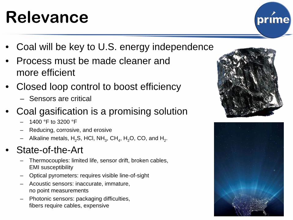
Relevance
• Coal will be key to U.S. energy independence• Process must be made cleaner and
more efficient• Closed loop control to boost efficiency
– Sensors are critical
• Coal gasification is a promising solution– 1400 °F to 3200 °F– Reducing, corrosive, and erosive– Alkaline metals, H2 S, HCl, NH3 , CH4 , H2 O, CO, and H2 .
• State-of-the-Art– Thermocouples: limited life, sensor drift, broken cables,
EMI susceptibility– Optical pyrometers: requires visible line-of-sight– Acoustic sensors: inaccurate, immature,
no point measurements– Photonic sensors: packaging difficulties,
fibers require cables, expensive
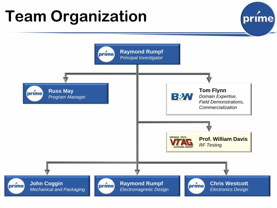
Team Organization
Raymond RumpfPrincipal Investigator
Russ MayProgram Manager
Raymond RumpfElectromagnetic Design
John CogginMechanical and Packaging
Tom FlynnDomain Expertise, Field Demonstrations, Commercialization
Prof. William DavisRF Testing
Chris WestcottElectronics Design

Prime Overview
• Virginia Tech spinoff company founded in 1999
• Historically developed fiber optic sensors for harsh environments
• Expanded technologies to include sensors, communications, and engineered materials for extreme applications
• 2009 Nominee for NewVA Technology Council (NCTC) “Rising Star” Award
• Federal R&D customer base includes USAF, NSF, DARPA, Navy, Army, DOE
Contract R&E• Government• Private Sector
Manufacture & SellJoint VentureIP LicensingSpin-Off

Prime Technologies (1 of 2)
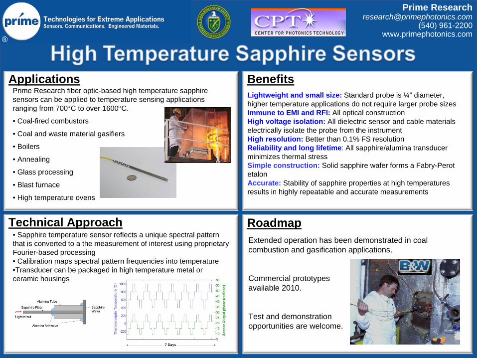
High Temperature Sensors
Turbines, combustion processes, process,
downhole oil and gas
Energy Harvesting Sensors
Self‐powered wireless sensors require no
batteries, fuel, or associated maintenance
Ultra-Fast Sensors
Temperature, pressure, strain, electric fields,
and magnetic fields
Ultra-Low Power Micro-Radios
Suitable for micro‐sensors. Relaxes power
requirements on power harvesting.
Microradio
Optowireless™
Wireless access to fiber optic backbone.
Powered by light itself.
Ultra-Low Power Radar
Ultra‐low power, compact, high resolution,
multipath immune, tracking and location.
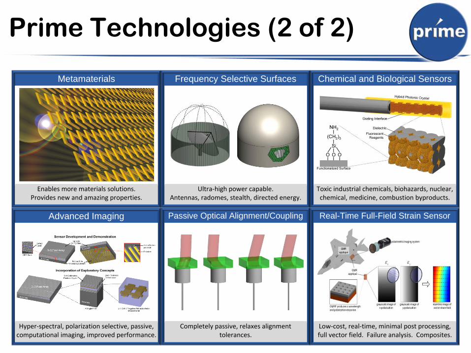
Prime Technologies (2 of 2)
Advanced Imaging
Hyper‐spectral, polarization selective, passive,
computational imaging, improved performance.
Passive Optical Alignment/Coupling
Completely passive, relaxes alignment
tolerances.
Chemical and Biological Sensors
Toxic industrial chemicals, biohazards, nuclear,
chemical, medicine, combustion byproducts.
Metamaterials
Enables more materials solutions.
Provides new and amazing properties.
Frequency Selective Surfaces
Ultra‐high power capable.
Antennas, radomes, stealth, directed energy.
Real-Time Full-Field Strain Sensor
Low‐cost, real‐time, minimal post processing,
full vector field. Failure analysis. Composites.
®
Prime [email protected]
(540) 961-2200www.primephotonics.com
Lightweight and small size: Standard probe is ¼” diameter, higher temperature applications do not require larger probe sizesImmune to EMI and RFI: All optical constructionHigh voltage isolation: All dielectric sensor and cable materials electrically isolate the probe from the instrument High resolution: Better than 0.1% FS resolutionReliability and long lifetime: All sapphire/alumina transducer minimizes thermal stressSimple construction: Solid sapphire wafer forms a Fabry-Perot etalonAccurate: Stability of sapphire properties at high temperatures results in highly repeatable and accurate measurements
Applications Benefits
Roadmap
Prime Research fiber optic-based high temperature sapphire sensors can be applied to temperature sensing applications ranging from 700C to over 1600C.
• Coal-fired combustors
• Coal and waste material gasifiers
• Boilers
• Annealing
• Glass processing
• Blast furnace
• High temperature ovens
Extended operation has been demonstrated in coal combustion and gasification applications.
Commercial prototypes available 2010.
Test and demonstration opportunities are welcome.
Technical Approach• Sapphire temperature sensor reflects a unique spectral pattern that is converted to a the measurement of interest using proprietary Fourier-based processing• Calibration maps spectral pattern frequencies into temperature•Transducer can be packaged in high temperature metal or ceramic housings
®
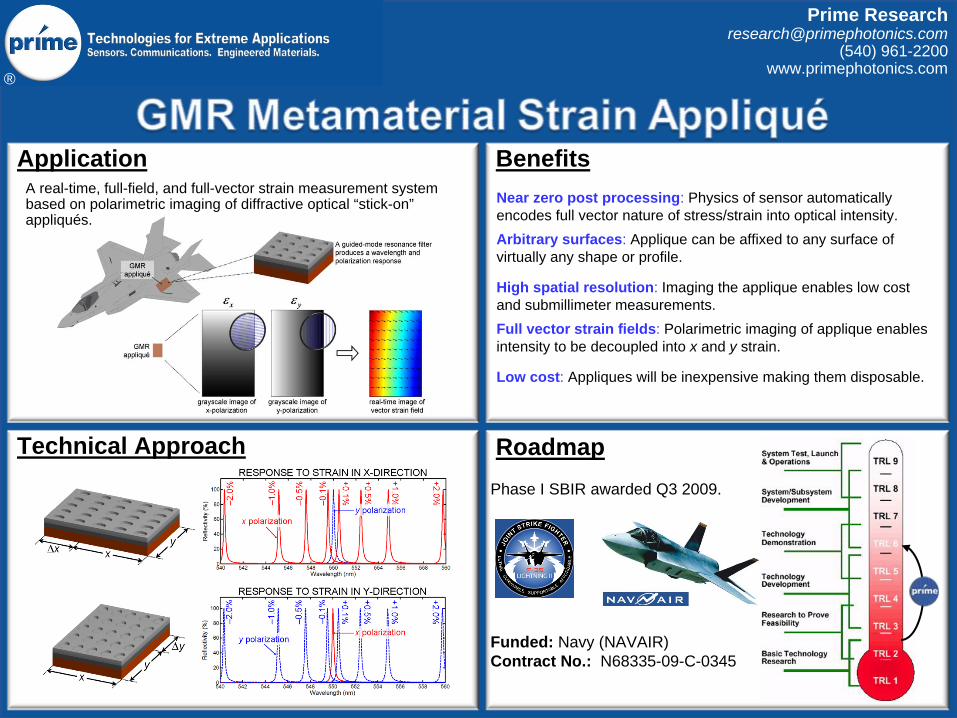
Near zero post processing: Physics of sensor automatically encodes full vector nature of stress/strain into optical intensity.Arbitrary surfaces: Applique can be affixed to any surface of virtually any shape or profile.
High spatial resolution: Imaging the applique enables low cost and submillimeter measurements.Full vector strain fields: Polarimetric imaging of applique enables intensity to be decoupled into x and y strain.
Low cost: Appliques will be inexpensive making them disposable.
Application Benefits
RoadmapTechnical Approach
Prime [email protected]
(540) 961-2200www.primephotonics.com
Phase I SBIR awarded Q3 2009.
Funded: Navy (NAVAIR)Contract No.: N68335-09-C-0345
A real-time, full-field, and full-vector strain measurement system based on polarimetric imaging of diffractive optical “stick-on” appliqués.
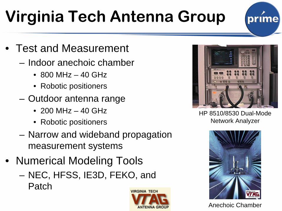
Virginia Tech Antenna Group
• Test and Measurement– Indoor anechoic chamber
• 800 MHz – 40 GHz• Robotic positioners
– Outdoor antenna range• 200 MHz – 40 GHz• Robotic positioners
– Narrow and wideband propagation measurement systems
• Numerical Modeling Tools– NEC, HFSS, IE3D, FEKO, and
Patch
HP 8510/8530 Dual-Mode Network Analyzer
Anechoic Chamber
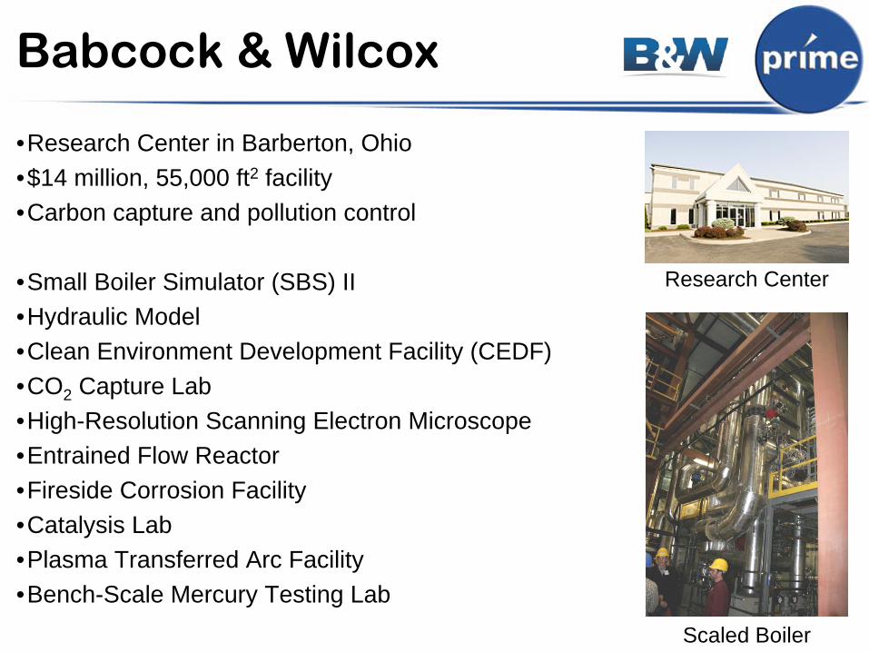
Babcock & Wilcox
•Research Center in Barberton, Ohio•$14 million, 55,000 ft2 facility•Carbon capture and pollution control
•Small Boiler Simulator (SBS) II•Hydraulic Model•Clean Environment Development Facility (CEDF)•CO2 Capture Lab•High-Resolution Scanning Electron Microscope•Entrained Flow Reactor•Fireside Corrosion Facility•Catalysis Lab•Plasma Transferred Arc Facility•Bench-Scale Mercury Testing Lab
Scaled Boiler
Research Center

Contract Details
• Funded by DOE NETL– Contract number DE-FE0001249
• Technical Contact– Robie Lewis, Fuels Division
• Three-Year, Two-Phase Project– Phase I: 1 Oct 2009 – 31 Mar 2011– Phase II: 1 Apr 2011 – 30 Sept 2012
• Total Contract Cost: $810,954– Funded Amount: $648,763– Cost Share: $162,191
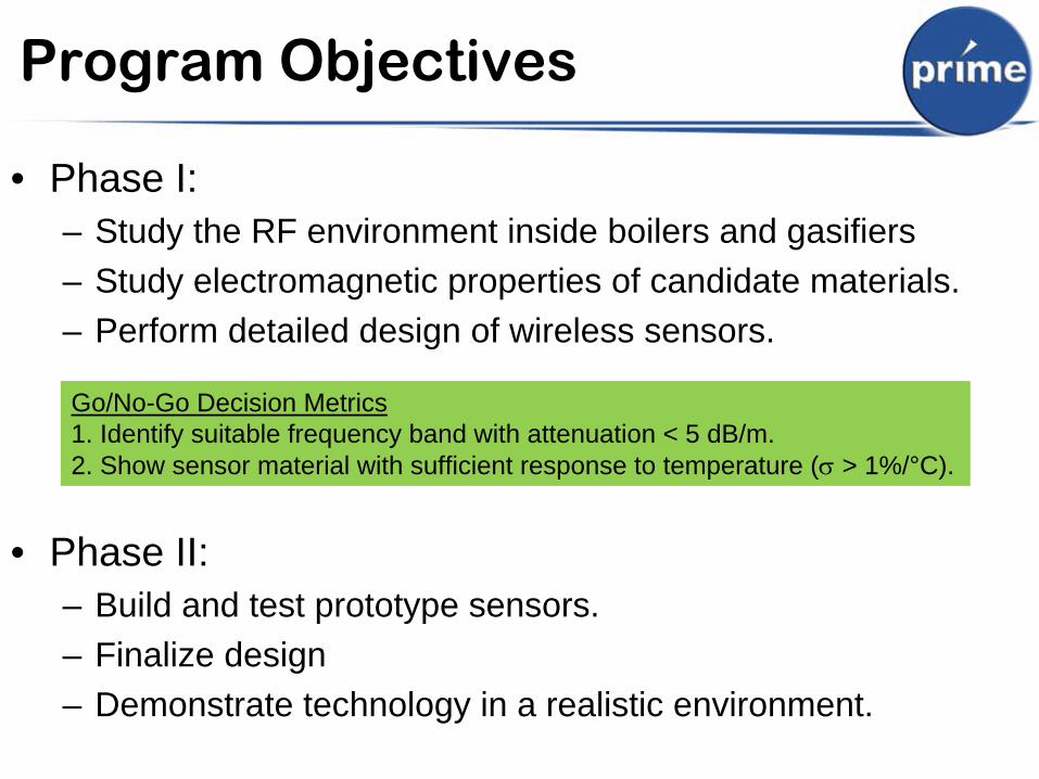
Program Objectives
• Phase I: – Study the RF environment inside boilers and gasifiers– Study electromagnetic properties of candidate materials.– Perform detailed design of wireless sensors.
• Phase II: – Build and test prototype sensors. – Finalize design– Demonstrate technology in a realistic environment.
Go/No-Go Decision Metrics1. Identify suitable frequency band with attenuation < 5 dB/m. 2. Show sensor material with sufficient response to temperature (
> 1%/°C).
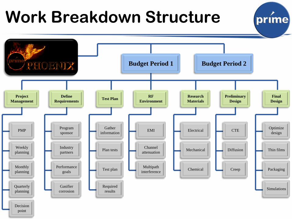
Work Breakdown Structure
Final Design
Optimize design
Thin films
Packaging
Simulations
Preliminary Design
CTE
Diffusion
Creep
Research Materials
Electrical
Mechanical
Chemical
RF Environment
EMI
Channel attenuation
Multipath interference
Test Plan
Gather information
Plan tests
Test plan
Required results
Define Requirements
Program sponsor
Industry partners
Performance goals
Gasifier corrosion
Project Management
PMP
Weekly planning
Monthly planning
Quarterly planning
Decision point
Budget Period 1 Budget Period 2
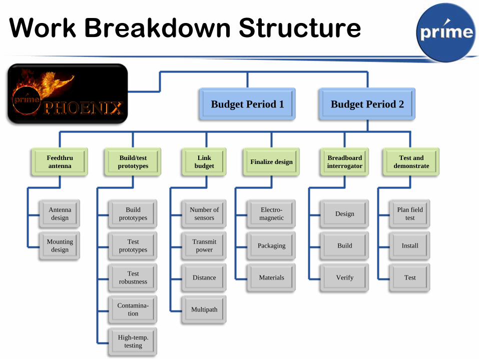
Work Breakdown Structure
Test and demonstrate
Plan field test
Install
Test
Breadboard interrogator
Design
Build
Verify
Finalize design
Electro- magnetic
Packaging
Materials
Link budget
Number of sensors
Transmit power
Distance
Multipath
Build/test prototypes
Build prototypes
Test prototypes
Test robustness
Contamina- tion
Feedthru antenna
Antenna design
Mounting design
Budget Period 2
High-temp. testing
Budget Period 1
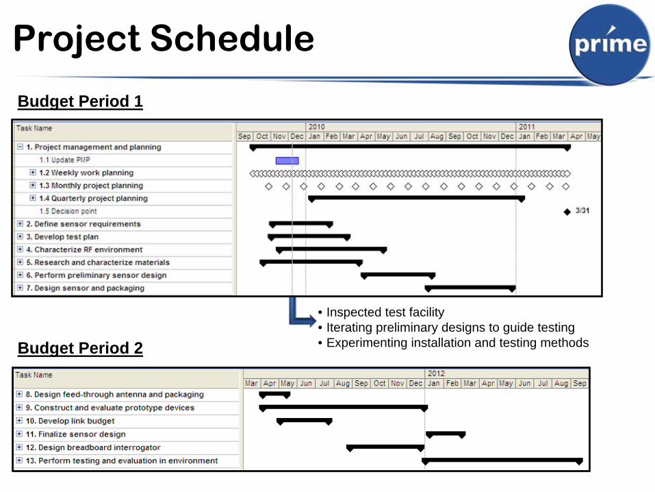
Project Schedule
Budget Period 1
Budget Period 2
• Inspected test facility• Iterating preliminary designs to guide testing• Experimenting installation and testing methods
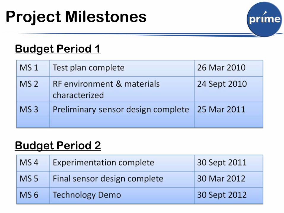
Project Milestones
Budget Period 1
Budget Period 2
Project Management Plan
• Weekly Work Planning Process– Monday: review weekly plan
with staff– Thursday: PI allocates resources
for next week.
• Monthly Planning Process– Update project budget based on accounting data– Monthly reviews with CEO
• Finances, technical status, schedule.
• Quarterly Planning and Reporting– PM updates schedule and financial status in PMP– PM submits tech report and updated PMP to DOE