Presentation for DESIGN FOR MANUFACTURING …...Design for Manufacturing (DFM) and Design for...
194
Presentation for DESIGN FOR MANUFACTURING AND ASSEMBLY DEPARTMENT OF MECHANICAL ENGINEERING M. TECH (CAD/CAM) : I SEM Dr. K CH APPARAO Associate Professor by
Transcript of Presentation for DESIGN FOR MANUFACTURING …...Design for Manufacturing (DFM) and Design for...
Presentation forDESIGN FOR MANUFACTURING AND ASSEMBLY
DEPARTMENT OF MECHANICAL ENGINEERINGM. TECH (CAD/CAM) : I SEM
Dr. K CH APPARAOAssociate Professor
by
2
UNIT - I
INTRODUCTION TO DESIGN

3
Design for Assembly (DFA)
DFA involves design for a product’s ease of assembly. It is concernedwith reducing the product assembly cost and minimising thenumber of assembly operations.
Both DFM and DFA seek to reduce material, overhead,and labour costs.
Design for Manufacturing and Assembly (DFMA)
Design for Manufacture and Assembly (DFMA) is design approachthat focuses on ease of manufacture and efficiency of assembly.

4
The main principles of DfMA are: Minimise the number of components: Thereby reducing assembly and ordering
costs, reducing work-in-process, and simplifying automation. Design for ease of part-fabrication: The geometry of parts is simplified and
unnecessary features are avoided. Tolerances of parts: Part should be designed to be within process capability. Clarity: Components should be designed so they can only be assembled one
way. Minimise the use of flexible components: Parts made of rubber, gaskets, cables
and so on, should be limited as handling and assembly is generally moredifficult.
Design for ease of assembly: For example, the use of snap-fits and adhesivebonding rather than threaded fasteners such as nuts and bolts. Where possiblea product should be designed with a base component for locating othercomponents quickly and accurately.
Eliminate or reduce required adjustments: Designing adjustments into aproduct means there are more opportunities for out-of-adjustment conditionsto arise.

5
Design for Manufacture and Assembly (DFMA) is design approach that focuses on ease of manufacture and efficiency of assembly.
By simplifying the design of a product it is possible to manufactureand assemble it more efficiently, in the minimum time and at alower cost.
It involves two methodologies – Design for Manufacture (DFM) andDesign for Assembly (DFA):
Design for Manufacture (DFM)DFM involves designing for the ease of manufacture of a product’sconstituent parts. It is concerned with selecting the most cost-effective materials and processes to be used in production, andminimising the complexity of the manufacturing operations.

Objectives of DFMA
Participants will understand:
– Differences and Similarities between Design for
Manufacturing and Design for Assembly
– Describe how product design has a primary influence
– Basic criteria for Part Minimization
– Quantitative analysis of a design’s efficiency
– Critique product designs for ease of assembly
– The importance of involving production engineers in DFMA
analysis
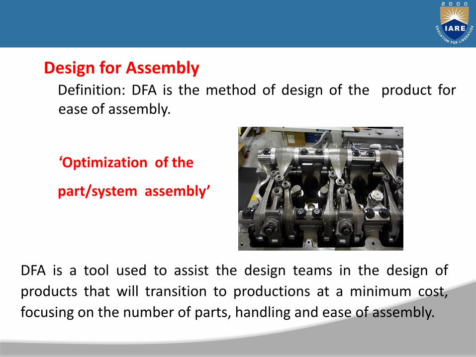
Design for AssemblyDefinition: DFA is the method of design of the product forease of assembly.
‘Optimization of the
part/system assembly’
DFA is a tool used to assist the design teams in the design of
products that will transition to productions at a minimum cost,
focusing on the number of parts, handling and ease of assembly.

Design for Manufacturing
Definition: DFM is the method of design for ease of
manufacturing of the collection of parts that will form the
product after assembly.
“…Optimization of the
manufacturing process…”
DFA is a tool used to select the most cost effective material and
process to be used in the production in the early stages of product
design.

Differences
Design for Assembly (DFA)
concerned only with reducing product assembly cost
– minimizes number of assembly operations
– individual parts tend to be more complex in design
Design for Manufacturing (DFM)
concerned with reducing overall part production cost
– minimizes complexity of manufacturing operations
– uses common datum features and primary axes

Similarities Both DFM and DFA seek to reduce material, overhead, and
labor cost.
They both shorten the product development cycle time.
Both DFM and DFA seek to utilize standards to reduce cost
Terminology
Design for Manufacturing (DFM) and Design for Assembly(DFA) are now commonly referred to as a single methodology,Design for Manufacturing and Assembly (DFMA) .

Design 70 - 80%
Manufacturing
20 - 30%
What Internal Organization has the most Influence overPrice, Quality, & Cycle Time?
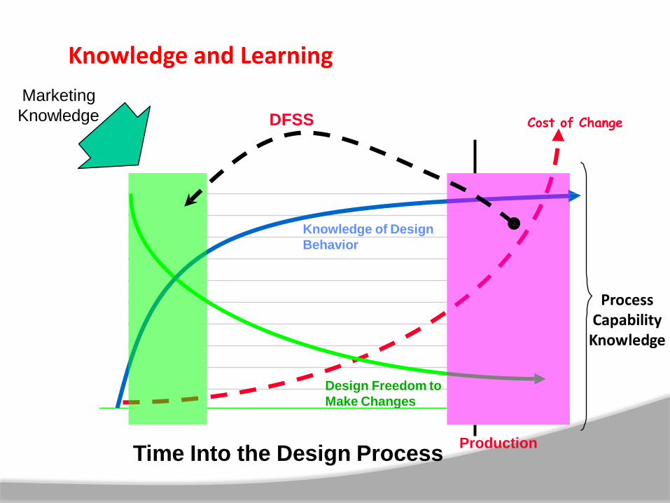
Time Into the Design Process
Perc
en
tag
e
100
90
80
70
60
50
40
30
20
10
0
0
0
0
0
0
0
0
0
0
10
9
8
7
6
5
4
3
2
1
High
Cost of Change
Design Freedom to
Make Changes
Knowledge of Design
Behavior
Production
Process Capability
Knowledge
DFSS
Marketing
Knowledge
Knowledge and Learning

Concept Design
Design for
Assembly
Design for
Manufacturing
Detailed Design
Optimize Design for
Part Count and
Assembly
Optimize Design for
Production Readiness
Sequence of Analysis

Design for Assembly
DFA is a process that REQUIRESinvolvement of Assembly Engineers
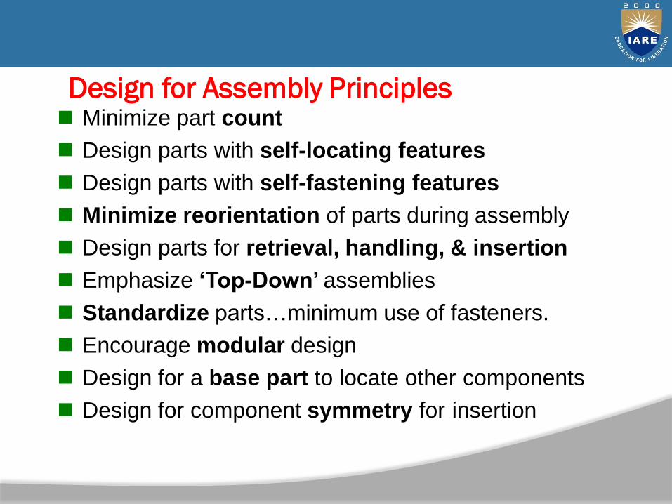
Design for Assembly Principles Minimize part count
Design parts with self-locating features
Design parts with self-fastening features
Minimize reorientation of parts during assembly
Design parts for retrieval, handling, & insertion
Emphasize „Top-Down‟ assemblies
Standardize parts…minimum use of fasteners.
Encourage modular design
Design for a base part to locate other components
Design for component symmetry for insertion
Introduction to Materials and Material Selection
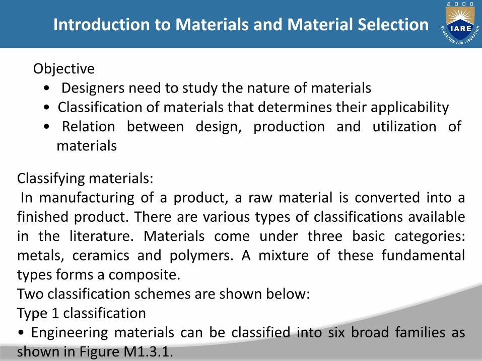
Objective• Designers need to study the nature of materials• Classification of materials that determines their applicability• Relation between design, production and utilization of
materials
Classifying materials:In manufacturing of a product, a raw material is converted into afinished product. There are various types of classifications availablein the literature. Materials come under three basic categories:metals, ceramics and polymers. A mixture of these fundamentaltypes forms a composite.Two classification schemes are shown below:Type 1 classification• Engineering materials can be classified into six broad families asshown in Figure M1.3.1.
Introduction to Materials and Material Selection
– Metals – Polymers – Elastomers – Ceramics – Glasses – Hybrid composite materials

Introduction to Materials and Material Selection

Introduction to Materials and Material Selection
Type 2 classification In this type of classification, engineering material can beclassified into two categories: Metals and non-metals as shownin FigureAgain non-metals are classified into organic & inorganic asshown in Figure M1.3.3 & Figure M1.3.4 respectively.Metals can be classified into two categories: ferrous and non-ferrous metal

Introduction to Materials and Material Selection

Introduction to Materials and Material Selection
Ceramics are compounds. These compounds contain a metallic and anon-metallic part. The non-metals can be oxygen, nitrogen and carbon.Examples of ceramics include carbides, clay, silica, alumina etc.Polymers are compounds which consist of repeating units in themcalled as “mers”. Mers share electrons to form very large molecules -usually of carbon and some other elements like oxygen, hydrogen,nitrogen, chlorine etc. Polymers are further classified intothermosetting, thermoplastics and elastomers. Some of the commonpolymers are polythene, PVC, etc.Composites consist of two or more phases of materials. The phases areprocessed separately and then bonded together to achieve propertiessuperior to the constituents. Some of the materials used in the phasesare wood or fiber etc. which are a homogenous mass bonded togetherwith epoxy. Some of the common applications of composites areaircraft, tennis rackets, car bodies, etc.

Introduction to Materials and Material Selection

Introduction to Materials and Material Selection
Introduction to Materials and Material Selection
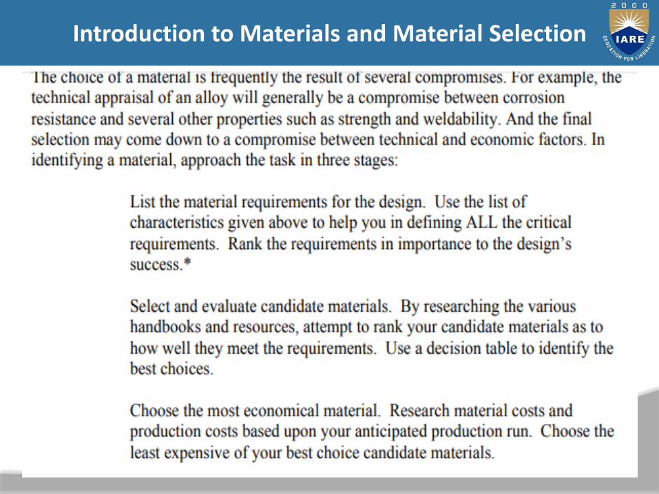
1. Selection by analysis The inputs to this method are the technical requirements. The
analysis proceeds in four steps: Translation of requirements: It is often expressed initially in
non-technical terms into statement of objectives andconstraints the design must meet.
Analysis of the component for which a material is sought,identifying performance matrices and expressing these asequations that measure performance.
Identification from these equations of the material propertiesthat determine performance.
Screening of a database of materials and their properties,eliminating those that fail to meet the constraints, and rankingthose that remain by their ability to maximize the performancematrices.

Introduction to Materials and Material Selection
2. Selection by synthesis
This process is experimental and depends on experience ofthe designer. The inputs here can include the designrequirements expressed as features showing intentions,aesthetics and perceptions.
Basically the solution will depend on previously solvedproblems that have some features common with the problemat hand. While this may be seen as a drawback since themethod uses past experience,
it encourages a kind of cross pollination where developmentsin one field can be adapted for use in another. Thismethodology is called technology coupling.
Introduction to Materials and Material Selection
3. Selection by similarity
A substitute material may be sought when the existing material isno longer available or fails to meet a design requirement. In suchcases an established material can be used instead of the existingone, simply because it may have the right mix of attributes andmay be meeting the design requirements.
4. Selection by inspirationDesigners usually get their ideas from other designers, colleaguesand from their environments. And many ideas are triggered byaccident, perhaps by some chance encounter with someone orsome situation. The encounter thus becomes inspiring andprovokes creative thinking. Such encounters can includeinteraction with materials, with products or by browsing books.

Introduction to Materials and Material Selection
Material Selection
Introduction to Materials and Material Selection
Material Selection
• As mechanical engineers we deal mostly with metals. Metalproperties tend to be well understood and metals aresomewhat forgiving materials. We can make small mistakes(sometimes big ones) and get away with a poor design as aresult of metal’s forgiving nature.
• We see ceramics and composites all around us, but they tend tobe used in special applications because of fabrication costs. Thishowever, is changing.
• Plastics are among the most common modern material choices.In large volume production, plastics are inexpensive. In smallvolume productions, plastics can be an extremely expensivechoice due to high tooling costs.

Introduction to Materials and Material Selection
Introduction to Materials and Material Selection
Introduction to Materials and Material Selection

DFA Analysis Worksheet
Cummins Tools
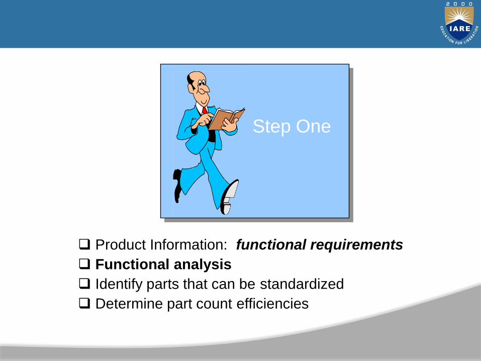
Product Information: functional requirements
Functional analysis
Identify parts that can be standardized
Determine part count efficiencies
Step One
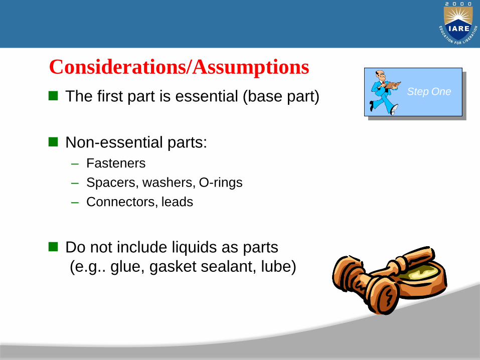
Considerations/Assumptions
The first part is essential (base part)
Non-essential parts:
– Fasteners
– Spacers, washers, O-rings
– Connectors, leads
Do not include liquids as parts
(e.g.. glue, gasket sealant, lube)
Step One

List of parts in the order of assembly
Assign/record part number
Parts Identification

So take it apart!

Count Parts & Interfaces List number of parts
(Np)
List number of interfaces (Ni)


UNIT - II
MACHINING PROCESS
45
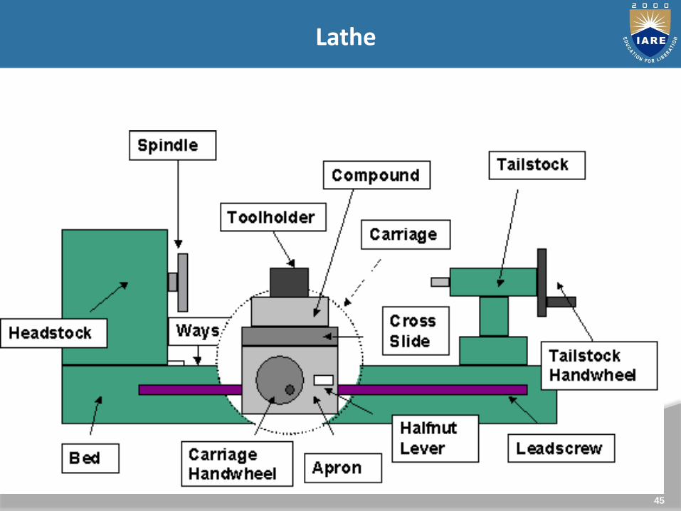
Lathe
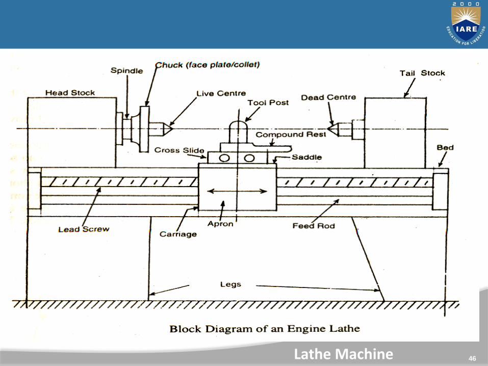
46Lathe Machine

47
Geared Head Stock

48
It’s on the other end of the bed from the headstock. It’s chief function is to hold the dead centre so that long work pieces can be supported between centres.
Tailstock -
49
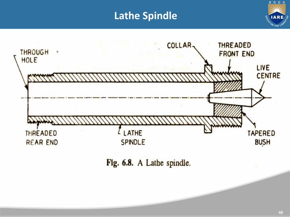
Lathe Spindle

50
In between the headstock & tailstock is the carriage. It’smovable on the bed ways and it’s purpose is to hold thecutting tool & to impart to it either longitudinal or crossfeed. It has five major parts:
a) Saddle
b) Cross slide
c) Compound rest
d) Tool post
e) Apron
Carriage

51
Lathe Carriage

52
Carriage
a) Saddle – The base of the carriage is the saddle which slides alongthe ways of the lathe bed and supports the cross-slide,compound rest & tool post.
b) Cross slide – It’s mounted on top of saddle. It provides cuttingtool motion which is perpendicular to the centre line of the latheitself. The cross feed movement may be controlled by manual orby power feed.
c) Compound rest– It’s also known as tool rest. It’s mounted on topof the cross-slide. It has a graduated circular base & can beswiveled around a vertical axis. It can be clamped to remain atany angular setting.
d) Tool post- It is mounted on the compound rest & slides in a T-slot. Cutting tool/ tool holder is firmly held in it.
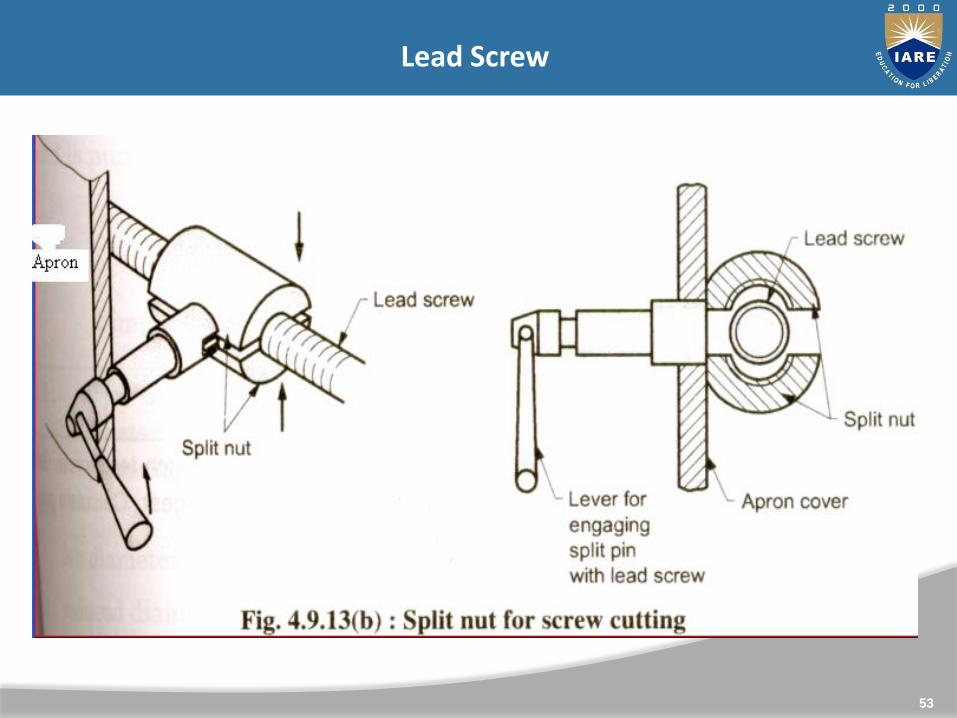
e) Apron – It’s the hanging part in front of the carriage. It is securedunderneath the saddle & hangs over the front of the bed.
53
Lead Screw

54
Lathe Operations : Turning
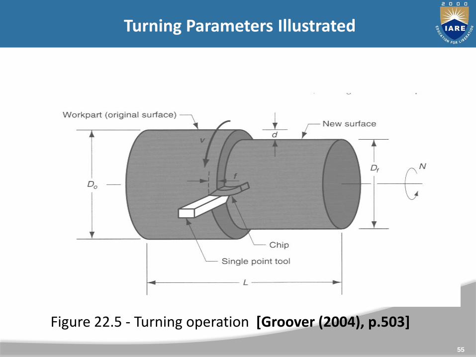
A single point cutting tool removes material from a rotatingwork piece to generate a rotationally symmetric shape
Machine tool is called a lathe
Types of cuts:FacingContour turningChamferingParting (Cut-off) / GroovingThreading
55
Turning Parameters Illustrated
Figure 22.5 - Turning operation [Groover (2004), p.503]

56
Facing
Figure 22.6 (a) facing
Tool is fed radially inward
57
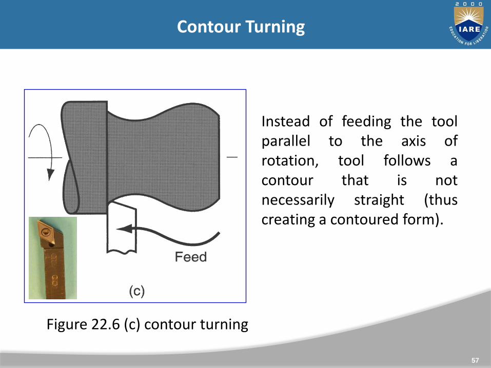
Contour Turning
Instead of feeding the toolparallel to the axis ofrotation, tool follows acontour that is notnecessarily straight (thuscreating a contoured form).
Figure 22.6 (c) contour turning
58
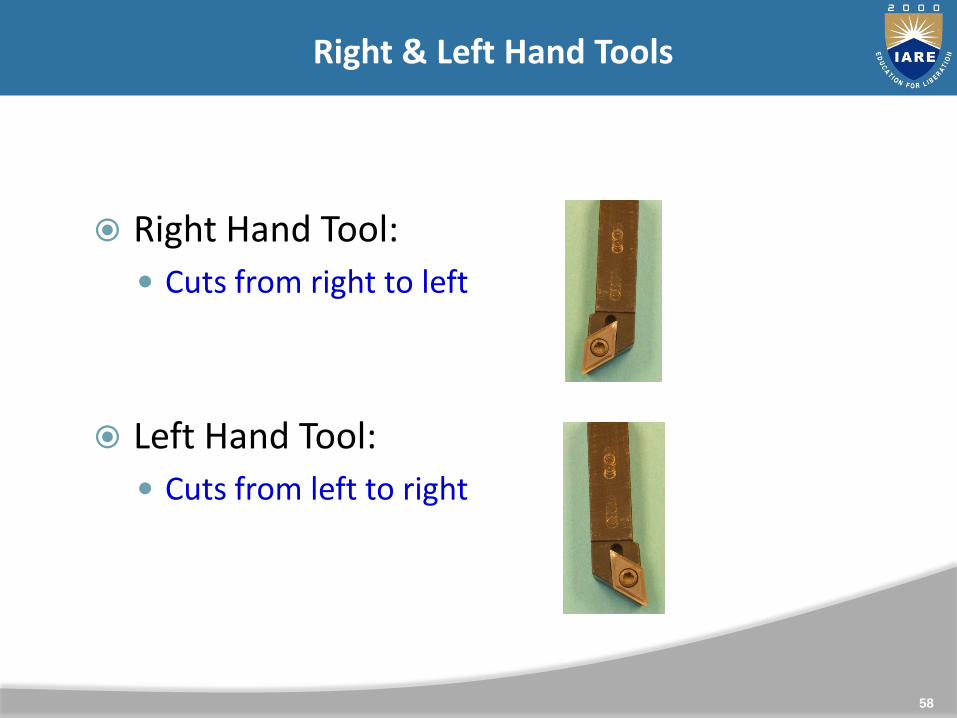
Right & Left Hand Tools
Right Hand Tool:
Cuts from right to left
Left Hand Tool:
Cuts from left to right
59
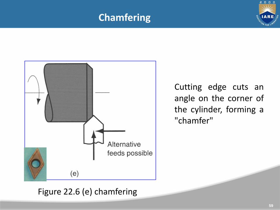
Chamfering
Cutting edge cuts anangle on the corner ofthe cylinder, forming a"chamfer"
Figure 22.6 (e) chamfering
60
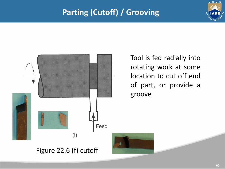
Parting (Cutoff) / Grooving
Tool is fed radially intorotating work at somelocation to cut off endof part, or provide agroove
Figure 22.6 (f) cutoff
61
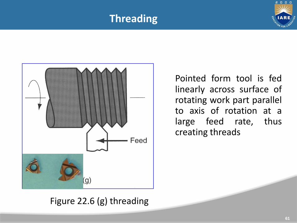
Threading
Pointed form tool is fedlinearly across surface ofrotating work part parallelto axis of rotation at alarge feed rate, thuscreating threads
Figure 22.6 (g) threading

62
Machining Processes Used to Produce Various Shapes: Milling
Milling

63
Milling and Milling Machines, Milling operations
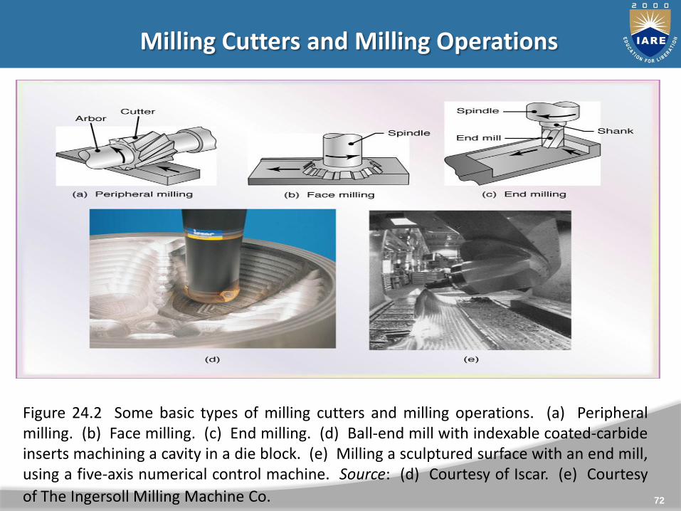
Milling: a process in which a rotating multi-tooth cutter removesmaterial while traveling along various axes with respect to thework-piece.
Figure 24.2: basic types of milling cutters & milling operations
In peripheral milling (also called plain milling), the axis of cutterrotation is parallel to the work-piece surface.
When the cutter is longer than the width of the cut, the process iscalled slab milling

64
Milling Principles
65
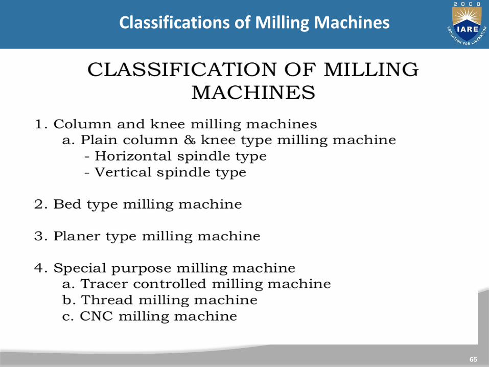
Classifications of Milling Machines

66
Horizontal Milling Machines

67

68
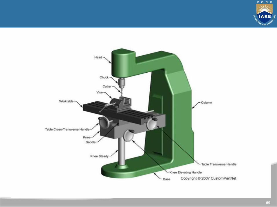
69

70
71
72
Milling Cutters and Milling Operations
Figure 24.2 Some basic types of milling cutters and milling operations. (a) Peripheralmilling. (b) Face milling. (c) End milling. (d) Ball-end mill with indexable coated-carbideinserts machining a cavity in a die block. (e) Milling a sculptured surface with an end mill,using a five-axis numerical control machine. Source: (d) Courtesy of Iscar. (e) Courtesy
of The Ingersoll Milling Machine Co.
73
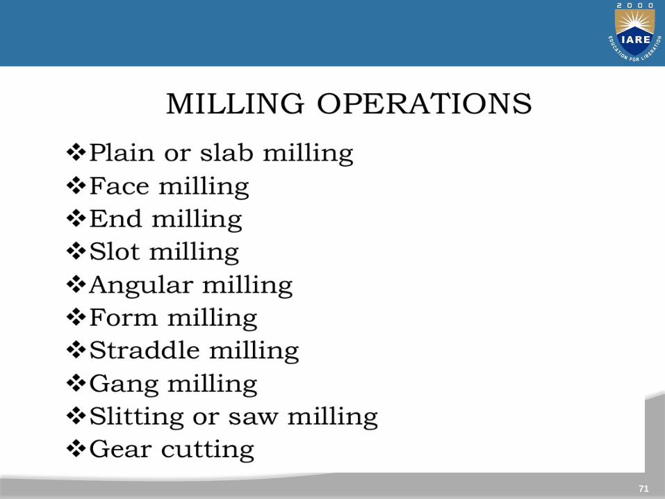
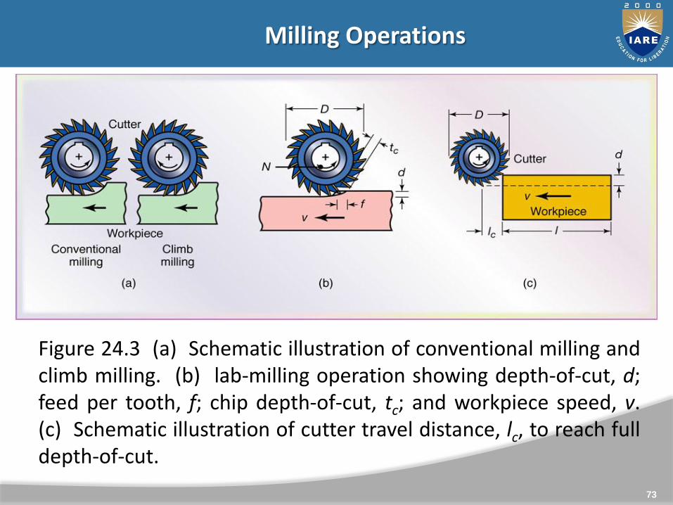
Milling Operations
Figure 24.3 (a) Schematic illustration of conventional milling andclimb milling. (b) lab-milling operation showing depth-of-cut, d;feed per tooth, f; chip depth-of-cut, tc; and workpiece speed, v.(c) Schematic illustration of cutter travel distance, lc, to reach fulldepth-of-cut.

74
Milling operations: up milling
Conventional Milling (Up Milling)
Max chip thickness is at the end of the cut Advantage: tooth engagement is not a function of work piece
surface characteristics, and contamination or scale on the surfacedoes not affect tool life. Cutting process is smooth Tendency for the tool to chatter The work piece has a tendency to be pulled upward, necessitating
proper clamping.

75
Climb Milling (Down Milling)
Cutting starts at the surface of the work piece.
Downward compression of cutting forces hold work piece inplace
Because of the resulting high impact forces when the teethengage the work piece, this operation must have a rigidsetup, and backlash must be eliminated in the table feedmechanism
Not suitable for machining work piece having surface scale.
Milling and Milling MachinesMilling operations: Down milling

76
Milling Parameters

77
Advanced Casting
One of the oldest materials shaping methods.
Casting means pouring molten metal into a mold with acavity of the shape to be made, and allowing it to solidify.When solidified, the desired metal object is taken outfrom the mold either by breaking the mold or taking themold apart. The solidified object is called the casting.
Intricate parts can be given strength and rigidityfrequently not obtainable by any other manufacturingprocess.

78
Advantages: Molten material can flow into very small sections so that
intricate shapes can be made by this process. It is possible to cast practically any material that is
ferrous or non-ferrous. As the metal can be placed exactly where it is required,
large saving in weight can be achieved. The necessary tools required for casting molds are very
simple and inexpensive. Size and weight of the product is not a limitation for the
casting process.
o Limitations:Dimensional accuracy and surface finish of the castings
79
Conventional casting process
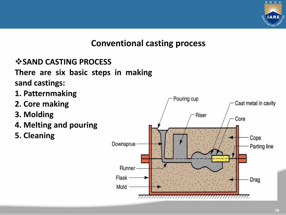
SAND CASTING PROCESSThere are six basic steps in makingsand castings:1. Patternmaking2. Core making3. Molding4. Melting and pouring5. Cleaning

80
81
CONVENTIONAL CONT….
DIE CASTING The process in which we use a die to make the castings
is called permanent mold casting The die consist of two part, one called the stationary
die or cover die which is fixed with to the casting m/c &2nd part called the ejector die is moved out for theextraction of the casting .
Because of the high pressure involved in die casting,any narrow sections, complex shape and fine surfacefinished can be easily produced.
Die casting m/c are of two type: hot chamber diecasting & cold chamber die casting

82
Conventional casting contd…
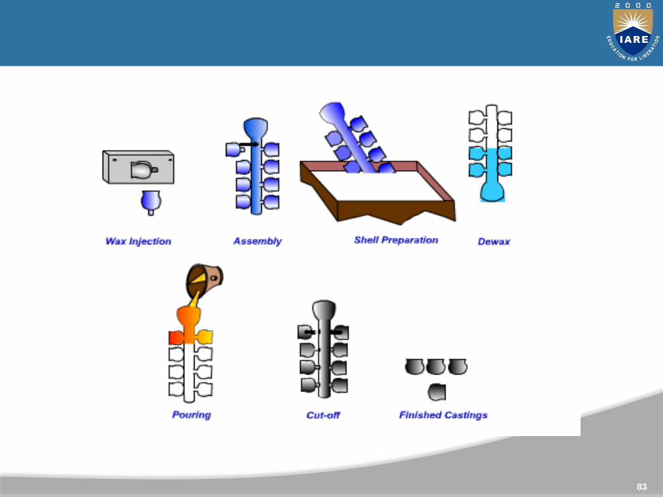
INVESTMENT CASTING In this process , the preparation of the pattern for every
casting made. To do this , molten wax which is used as a pattern material is
injected under pressure into a metallic die which has of thecavity of the casting to be made.
Wax when allowed to solidify would produce the pattern.Products artefacts , jewellery, & surgical instrument,
presently vanes & blades for gas turbines, wave guider forradar and triggers for fire arms.
83

84
CENTRIFUGAL CASTING
the mold is rotated rapidly about its central axis as the metalis poured into it.
Because of the centrifugal force, a continuous pressure willbe acting on the metal as it solidifies. The slag, oxides andother inclusions being lighter, get separated from the metaland segregate towards the center.
This process is normally used for the making of hollow pipes,tubes, hollow bushes, etc ., which are axisymmetric with aconcentric hole.
The mold can be rotated about a vertical, horizontal or aninclined axis or about its horizontal and vertical axessimultaneously
CENTRIFUGAL CASTING

85
ADVANCES IN CASTING
Semi-solid manufacturing process of magnesium alloys by twin-roll casting: Magnesium is 36% lighter per unit volume than aluminum and
78% lighter than iron. When alloyed, magnesium has thehighest strength-to-weight ratio of all the structural metals.
Utilization of magnesium alloys has mainly depended on castingtechnology and SSM.
Unfortunately, the major barrier to greatly increasedmagnesium alloy use in cars is still primarily high manufacturingcost. So for solving this problem is to develop semi-solid rollstrip casting technology to manufacture magnesium sheetalloys economically while maintaining high quality.

86
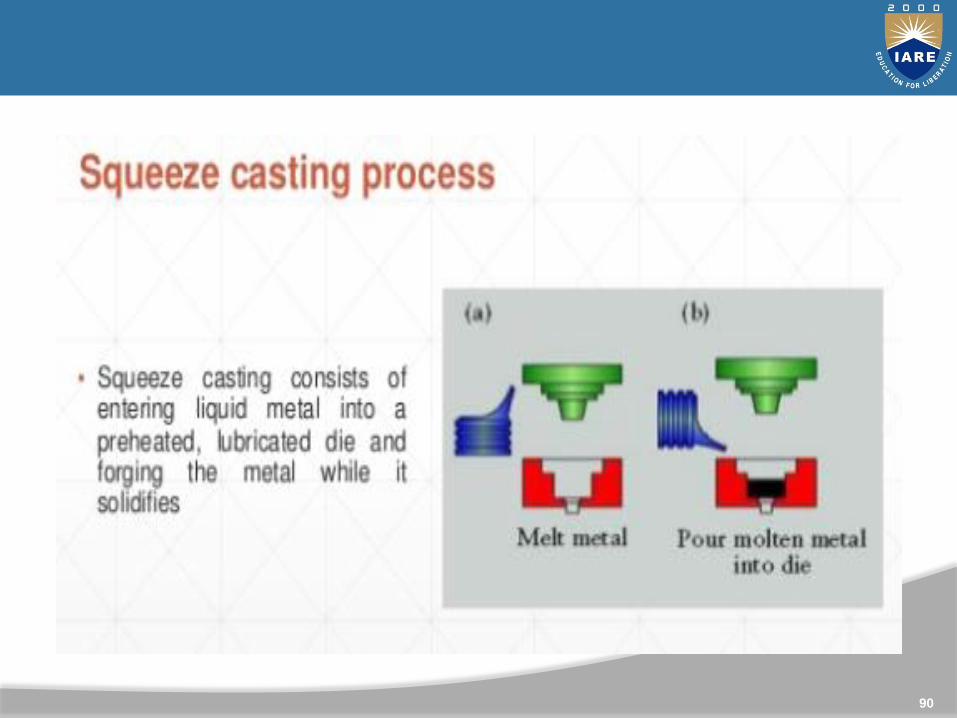
Squeeze casting squeeze casting has greater potential to create less defective
cast components. Squeeze casting (SC) is a fabrication technique where
solidification is promoted under high pressure within a re-usable die.
It is a metal-forming process, which combines permanentmould casting with die forging into a single operation wheremolten metal is solidified under applied hydrostatic pressure.
In this process a die set is placed on a hydraulic press andpreheated, and the exact amount of molten alloy is pouredinto the lower half of the open die set, the press closed sothat the alloy fills the cavity and the pressure maintaineduntil complete solidification occurs.

87
the SC-fabricated engineering components are fine grainedwith excellent surface finish and have almost no porosity. Themechanical properties of these parts are significantlyimproved over those of conventional castings.

88

89
90
91
92
Advantages
Offers a broader range of shapes and components than
other manufacturing methods.
Little or no machining required post casting process
Low levels of porosity
Good surface structure
Fine micro-structures with higher strength components
No waste material 100% utilization.
93
UNIT - III
WELDING

Welding is defined as an localized coalescence of metals, wherein coalescence is obtained by heating to suitable temperature,with or without the application of pressure and with or withoutthe use of filler metal.
OR
Welding is a process of joining similar metals by applicationof heat with or without application of pressure and addition offiller material
94
Classifications of Welding

95
Classifications of Welding
Welding process can be classified into different categoriesdepending upon the following criteria :
(a)It can be classified as fusion welding or pressure weldingdepending upon on the application of heat. If application of heat isnot required, it is called pressure welding.(b)In case of fusion welding it can classified low temperaturewelding and high temperature welding. When heat is generated todevelop low temperature it is called low temperature welding likesoldering and brazing. Other fusion welding methods are hightemperature welding methods.
(c)Fusion welding can also be classified on the basis of method ofheat generation
like gas welding, electric arc welding, resistance welding, thermitwelding, etc.

96
Classifications of Welding

97
Oxy acetylene Welding

98
Materials Suitable for Oxy acetylene welding

99
OXY-ACETYLENE WELDING(OAW) STATION
100
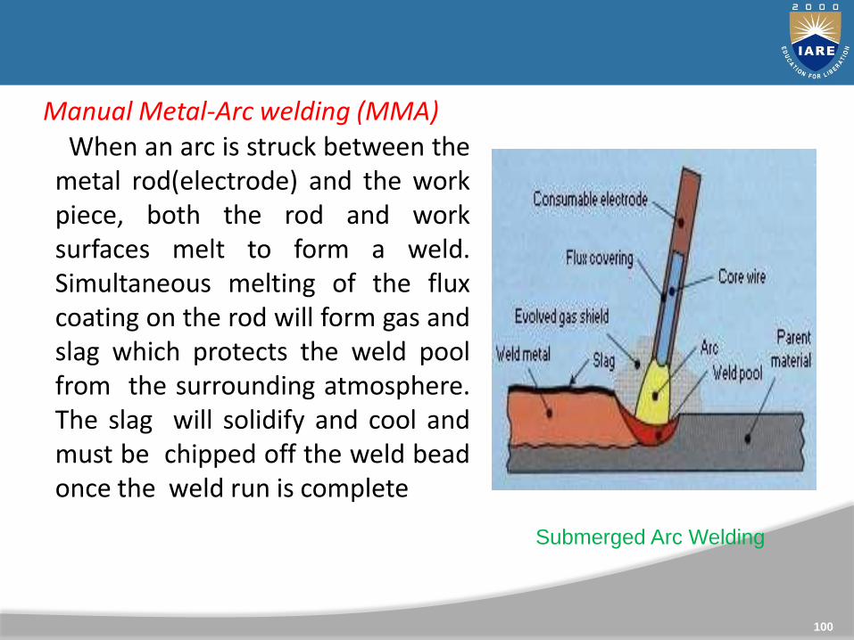
Manual Metal-Arc welding (MMA)When an arc is struck between the
metal rod(electrode) and the workpiece, both the rod and worksurfaces melt to form a weld.Simultaneous melting of the fluxcoating on the rod will form gas andslag which protects the weld poolfrom the surrounding atmosphere.The slag will solidify and cool andmust be chipped off the weld beadonce the weld run is complete
Submerged Arc Welding
101
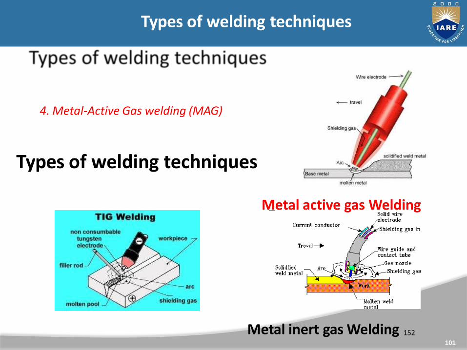
4. Metal-Active Gas welding (MAG)
Types of welding techniques
Metal active gas Welding
Metal inert gas Welding 152
Types of welding techniques

102
Stud Welding
Shop welding Field welding

103
Welding process
104
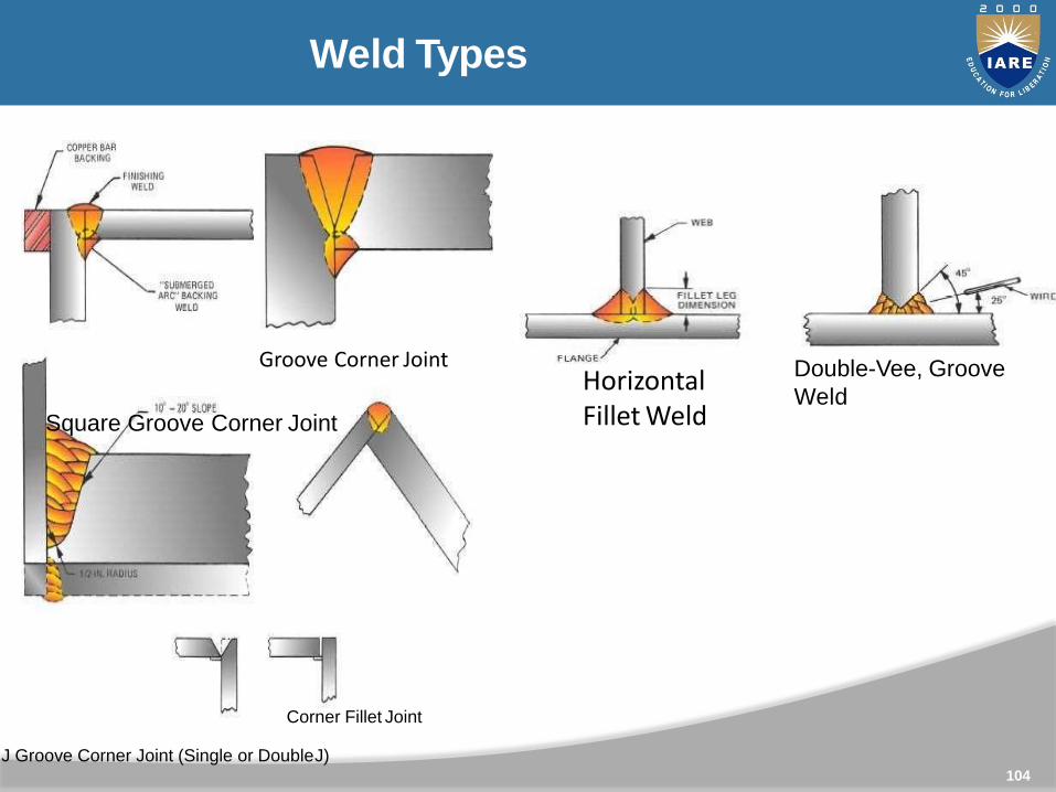
Horizontal Fillet Weld
Double-Vee, Groove
Weld
Weld Types
e Groove Corner Joint
Square Groove Corner Joint
Corner Fillet Joint
J Groove Corner Joint (Single or DoubleJ)
105
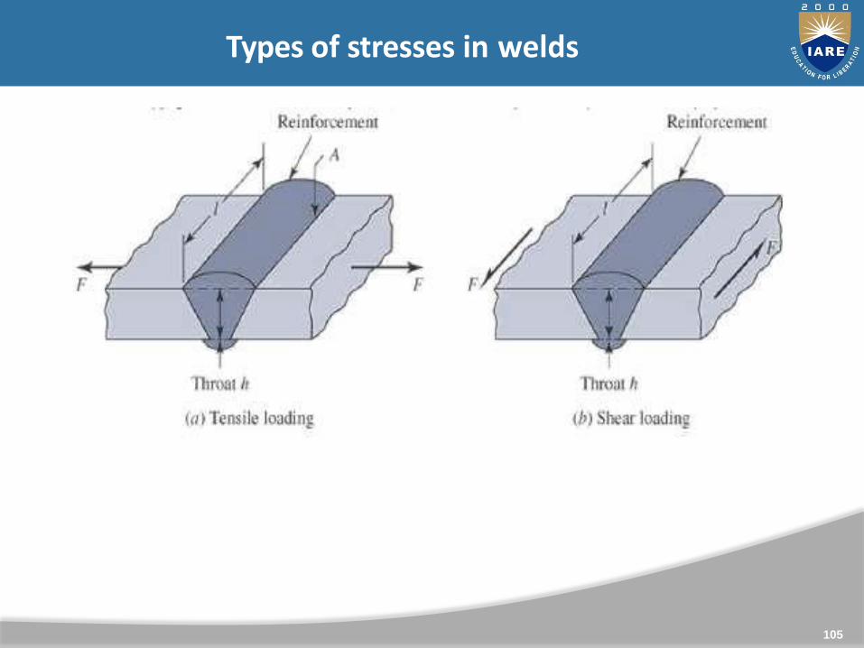
Types of stresses in welds
106
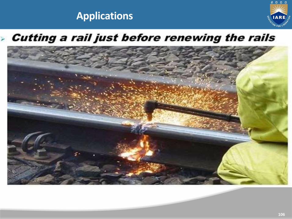
Applications

107
Applications
•Oxygen cutting would be useful only for those materials which
readily get oxidized and the oxides have lower melting points than
the metals. So it is most widely used for ferrous materials. ƒ
• Oxygen cutting is NOT used for materials like aluminium, bronze,stainless steel
which resist oxidation. ƒ
• Cutting of high carbon steels and cast irons require specialattention due to
formation of heat affected zone (HAZ) where structural transformation occurs.

108
Arc welding
The arc welding is a fusion welding process in which the heatrequired to fuse the metal is obtained from an electric arcbetween the base metal and an electrode.
The electric arc is produced when two conductors are touchestogether and then separated by a small gap of 2 to 4 mm, suchthat the current continues to flow, through the air. Thetemperature produced by the electric arc is about 4000°C to
6000°C.

109
Types of stresses in welds

110
Commonly encountered weld defects

111
Commonly encountered weld defects
Excess weld metal
Undercut
Overlap
Linear misalignment
111

112
FORGING
Forging may be defined as a metal working process by whichmetals and alloys are plastically deformed to desiredshapes by the application of compressive force. Forgingmay done either hot or cold.
• Forging - defined as metal working process by whichmetals and alloys are plastically deformed to thedesired shapes by the application of compressiveforces.
• Classification:
Open Die Forging
Impression / closed die forging
113
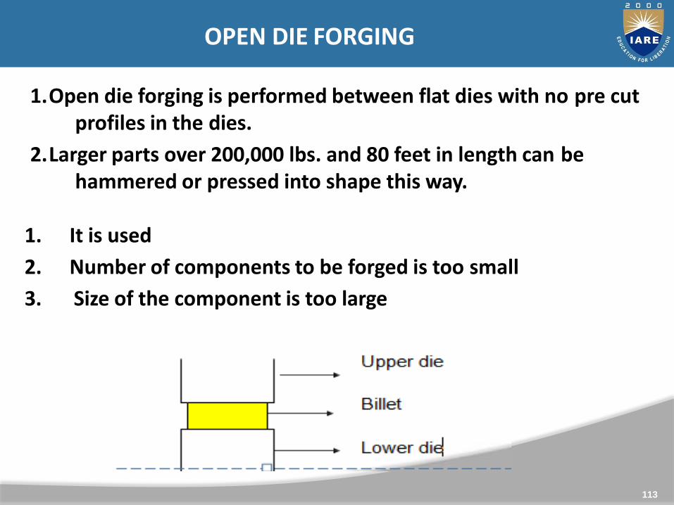
OPEN DIE FORGING
1.Open die forging is performed between flat dies with no pre cutprofiles in the dies.
2.Larger parts over 200,000 lbs. and 80 feet in length can behammered or pressed into shape this way.
1. It is used
2. Number of components to be forged is too small
3. Size of the component is too large
114
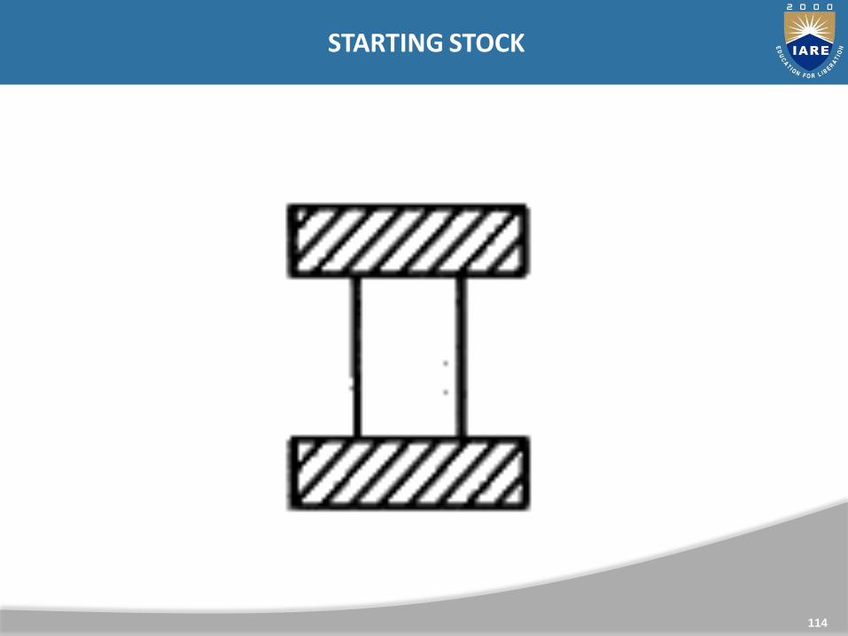
STARTING STOCK

115
PRELIMINARY UPSETTING

116
IMPRESSION DIE FORGING
1. Impression Die Forging Process operations. In impression dieforging, two dies are brought together and the work pieceundergoes plastic deformation until its enlarged sides touchthe side walls of the die. Then, a small amount of materialbegins to flow outside the die impression forming flash that isgradually thinned.
2. The flash cools rapidly and presents increased resistanceto deformation and helps build up pressure inside the bulkof the work piece that aids material flow into unfilledimpressions.

117
Impression Die

118
Impression Die Forging

119
Forging Defects
1. Incomplete forging penetration (Dentritic structure will not bebroken at the interior surface)
2. Surface crack3. High sulphur concentration in the furnace atmosphere can
produce HOTSHORTNESS in Steel & Nickel
4. Crack at Flash
5. Cold shut
6. Loose Scale or lubricant may accumulate in deep recess of thedie
7. Incomplete decaling of work piece
8. Internal cracks can develop during upsetting
9. Laps (Metal Fold)
10. Mismatch

120
Forging operations
1. UPSETTING
2. HEADING
3. FULLERING
4. FLATTENING
5. EDGING
6. DRAWING OR NECKING
7. SETTING DOWN
8. SWAGING
9. PUNCHING
10. PIERCING
11. BENDING

121
Swaging
Swaging--This operation is related to the open die forging
process whereby the stock is drawn out between flat, narrow
dies. But instead of the stock, the hammer is rotated to produce
multiple blows, sometimes as high as 2,000 per minute. It is a
useful method of primary working, although in industrial
production its role is normally that of finishing. Swaging can be
stopped at any point in the length of stock and is often used for
pointing tube and bar ends and for producing stepped columns
and shafts of declining diameter.
122
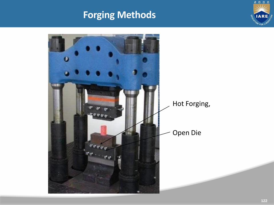
Forging Methods
Hot Forging,
Open Die
123
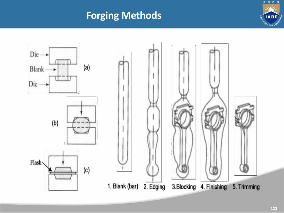
Forging Methods

124
Forging Methods

125
Impression Die Forging
(a) forge hot billet to max diameter
125
(b) “fuller: tool to mark step-locations
(c) Forge right side
(d) reverse part, forge left side
(e) finish (dimension control)
Forging Methods

126
Forging Methods

127
UNIT - IV
ASSEMBLY ADVANTAGES
Design for Manufacturing
Design for Production
Design for Assembly
Design for Recycling/Disposal
Design for Life Cycle
Prototyping
Design for X Topics
Sketches, drawings, product specifications, anddesign alternatives.
A detailed understanding of production andassembly processes
Estimates of manufacturing costs, productionvolumes, and ramp-up timing.
Gathering DFM Information

Estimate the Manufacutring
Costs
Consider the Impact of DFM
Decisions on Other Factors
Recompute the
Manufacturing Costs
Reduce the Costs of
Supporting Production
Reduce the Costs of
Assembly
Reduce the Costs of
Components
Good
enough
?
N
Y
Acceptable Design
Proposed Design
DFM Method

Finished GoodsManufacturing System
Equipment Information Tooling
WasteServicesSuppliesEnergy
Raw Materials
Labor
Purchased
Components
Estimate the Manufacturing Costs

Sum of all the expenditures for the inputs of the system (i.e.purchased components, energy, raw materials, etc.) and fordisposal of the wastes produced by the system
Manufacturing Costs Defined
Manufacturing Cost
OverheadAssemblyComponents
Standard Custom LaborEquipment
and ToolingSupport
Indirect
Allocation
Raw
MaterialProcessing Tooling
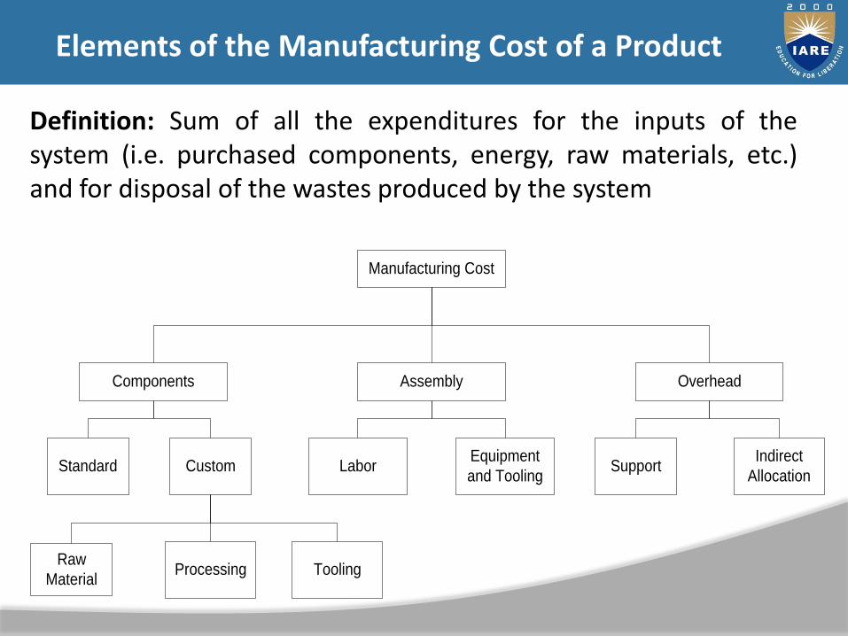
Elements of the Manufacturing Cost of a Product
Definition: Sum of all the expenditures for the inputs of thesystem (i.e. purchased components, energy, raw materials, etc.)and for disposal of the wastes produced by the system

Component Costs (parts of the product) Parts purchased from supplier
Custom parts made in the manufacturer’s own plant or by suppliers according to the manufacturer’s design specifications
Assembly Costs (labor, equipment, & tooling)
Overhead Costs (all other costs) Support Costs (material handling, quality assurance, purchasing,
shipping, receiving, facilities, etc.)
Indirect Allocations (not directly linked to a particular product but must be paid for to be in business)
Manufacturing Cost of a Product

Fixed Costs – incurred in a predetermined amount, regardless ofnumber of units produced (i.e. setting up the factory work areaor cost of an injection mold)
Variable Costs – incurred in direct proportion to the number ofunits produced (i.e. cost of raw materials)
Fixed Costs vs. Variable Costs

Understand the Process Constraints and Cost Drivers.
Redesign Components to Eliminate Processing Steps.
Choose the Appropriate Economic Scale for the Part Process.
Standardize Components and Processes.
Adhere to “Black Box” Component Procurement.
Reduce the Cost of Components

• Redesign costly parts with the same performance while avoiding high manufacturing costs.
• Work closely with design engineers—raise awareness of difficult operations and high costs.
Understand the Process Constraints and Cost Drivers

Reduce the number of steps of the production process
Will usually result in reduce costs
Eliminate unnecessary steps.
Use substitution steps, where applicable.
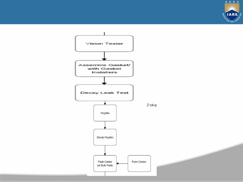
Analysis Tool – Process Flow Chart and Value Stream Mapping
Redesign Components to Eliminate Processing Steps

Economies of Scale – As production volume increases, manufacturing costs usually decrease.
Fixed costs divided among more units.
Variable costs are lower since the firm can use more efficient processes and equipment.
Choose the Appropriate Economic Scale for the Part Process

Economies of Scale – The unit cost of a component decreases as the production volume increases.
Standard Components—common to more than one product.
Analysis tools – group technology and mass customization.
Standardize Components and Processes
Adhere to “Black Box” Component Procurement
Black box—only give a description of what the component has to do, not how to achieve it.
Successful black box design requires clear definitions of the functions, interfaces, and interactions of each component.

Design for Assembly (DFA) index
Integrated Parts (Advantages and Disadvantages)
Maximize Ease of Assembly
Consider Customer Assembly
Reduce the Costs of Assembly

Boothroyd Dewhurst DFM & A
Munro & Assoc. (Design Prophet/Profit)
Others
Design for Assembly Index
DFA Systems
DFA index =
(Theoretical minimum number of parts) x (3 seconds)
Estimated total assembly time

Does the part need to move relative to the rest of theassembly?
Must the part be made of a different material from the restof the assembly for fundamental physical reasons?
Does the part have to be separated from the assembly forassembly access, replacement, or repair?
Determining the Theoretical Minimum Number of Parts
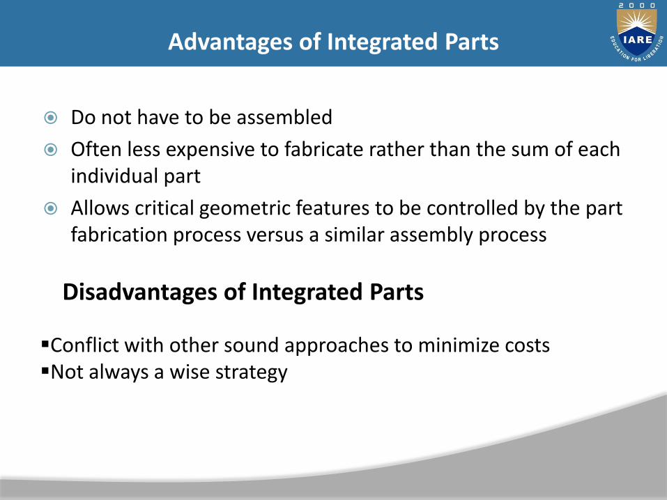
Do not have to be assembled
Often less expensive to fabricate rather than the sum of each individual part
Allows critical geometric features to be controlled by the part fabrication process versus a similar assembly process
Advantages of Integrated Parts
Disadvantages of Integrated Parts
Conflict with other sound approaches to minimize costsNot always a wise strategy

Part is inserted from the top of the assembly
Part is self-aligning
Part does not need to be oriented
Part requires only one hand for assembly
Part requires no tools
Part is assembled in a single, linear motion
Part is secured immediately upon insertion
Minimize Ease of Assembly
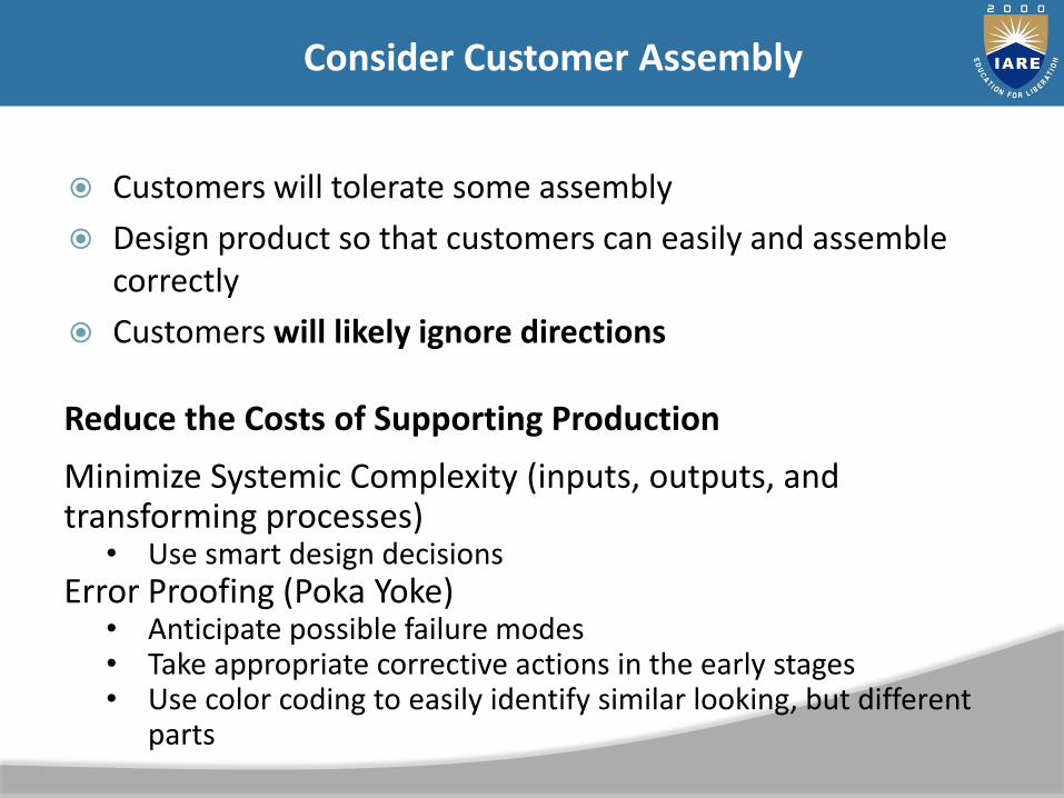
Customers will tolerate some assembly
Design product so that customers can easily and assemble correctly
Customers will likely ignore directions
Consider Customer Assembly
Reduce the Costs of Supporting Production
Minimize Systemic Complexity (inputs, outputs, and transforming processes)
• Use smart design decisionsError Proofing (Poka Yoke)
• Anticipate possible failure modes• Take appropriate corrective actions in the early stages• Use color coding to easily identify similar looking, but different
parts
Development Time
Development Cost
Product Quality
External Factors
Component reuse
Life cycle costs
Consider the Impact of DFM Decisions on Other Factors

1. Design Organization
2. Timing of Production
3. Material Identification
4. Specific Design Details (outputs)
Design for Production

At various design stages Concept
○ Production Input
Functional○ None
Transition○ Tactics
Work Instruction○ Production Preparation
Production Input
1. In proper level of detail at proper stage
2. In proper form
3. Just-in-time
New Idea: Provide Production Inputs
Problems with Old Approach
Work is carried out from beginning to end at each stage Too slow Needs continuous recycling
1. Use Common Sense
2. Plan and Define
3. Consider Available Facilities
4. Consider Available Tools
5. Consider Available Worker Skills
6. Employ Simplicity
7. Standardize
Design for Production General Principles

1. Minimize Total Number of Parts
2. Develop a Modular Design
3. Minimize Part Variations
4. Design Parts to be Multifunctional
5. Design Parts for Multiuse
6. Design Parts for Ease of Fabrication
7. Avoid Separate Fasteners
8. Minimize Assembly Direction (Top Down Direction Preferred)
9. Maximize Compliance in Assembly
10. Minimize Handling in Assembly
11. Minimize complexity of Design
12. Maximize common Jigs and Fixtures
13. Optimize Work Position
14. Ease Access
Design for Production Guidelines

Two dimensions
Physical vs. Analytical
Comprehensive vs. Focused
Types of Prototypes
Physical vs. Analytical
Physical• Tangible artifacts created to approximate the product• Used for testing and experimentation
Analytical• Represents the product in a nontangible, usually
mathematical manner• Product is analyzed, not built

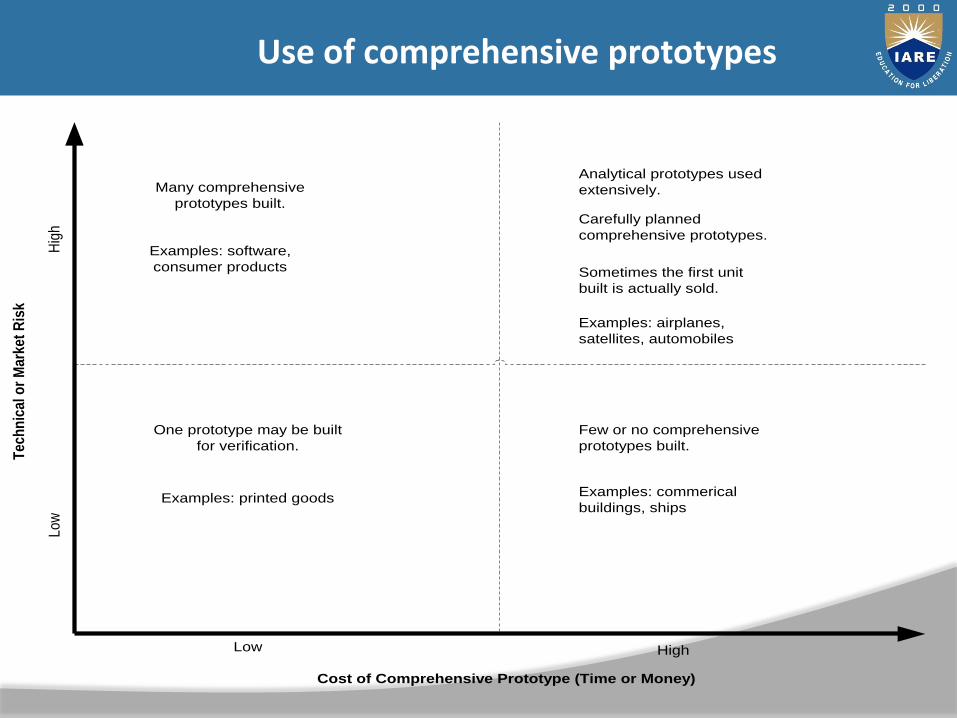
Comprehensive
Implement all (or most) of the attributes of the product
Full-scale
Fully operational version of the product
Focused
Implement a few of the attributes of the product
Use two or more focused prototypes together to investigate the overall performance of a product
Comprehensive vs. Focused

Learning Will it work?
How well does it meet the customer needs?
Communication Within the company
With customers, vendors, and suppliers
Integration Subsystems and components work together
Milestones Product achieved a desired level of functionality
Prototype Uses

Analytical Prototypes are generally more flexible than PhysicalPrototypes
Physical Prototypes are required to detect unanticipatedphenomena
A Prototype may reduce the risk of costly iterations
A Prototype may expedite other development steps
A Prototype may restructure task dependencies
Principles of Prototyping
Tech
nic
al o
r M
ark
et
Ris
k
Hig
hL
ow
Cost of Comprehensive Prototype (Time or Money)
Low High
One prototype may be built
for verification.
Examples: printed goods
Few or no comprehensive
prototypes built.
Examples: commerical
buildings, ships
Many comprehensive
prototypes built.
Examples: software,
consumer products
Analytical prototypes used
extensively.
Carefully planned
comprehensive prototypes.
Sometimes the first unit
built is actually sold.
Examples: airplanes,
satellites, automobiles
Use of comprehensive prototypes

3D Computer Modeling
Easily visualize the 3D form of the design
Automatically compute physical properties
Other more focused descriptions can be created based on one design
Detect geometric interference am
Free-Form Fabrication (or Rapid Prototyping)
3D printers that create physical objects directly from 3D computer models
Less expensive
Reduce product development time, improve resulting product.
Prototyping Technologies

Planning for Prototypes
• Define the purpose of the prototype• Establish the level of approximation of the prototype• Outline an experimental plan • Create a schedule for procurement, construction, and test
Define the Purpose
• List specific learning and communication goals • List any integration needs• Determine if the prototype is intended to be one of the
major milestones of the overall product development

Determine physical or analytical prototype
Choose the simplest prototype that will serve the purpose established in step 1.
Consider existing prototypes or a another prototype being built that can be borrowed
Establish the Level of Approximation
Outline an Experimental PlanOutline an Experimental Plan
• Use prototype for experimentation• Extract the maximum value from the prototyping activity.• Identify the variables of the experiment, test protocol, plan
for analyzing the resulting data
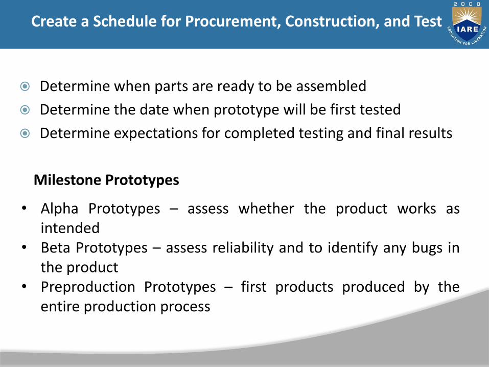
Determine when parts are ready to be assembled
Determine the date when prototype will be first tested
Determine expectations for completed testing and final results
Create a Schedule for Procurement, Construction, and Test
Milestone Prototypes
• Alpha Prototypes – assess whether the product works asintended
• Beta Prototypes – assess reliability and to identify any bugs inthe product
• Preproduction Prototypes – first products produced by theentire production process
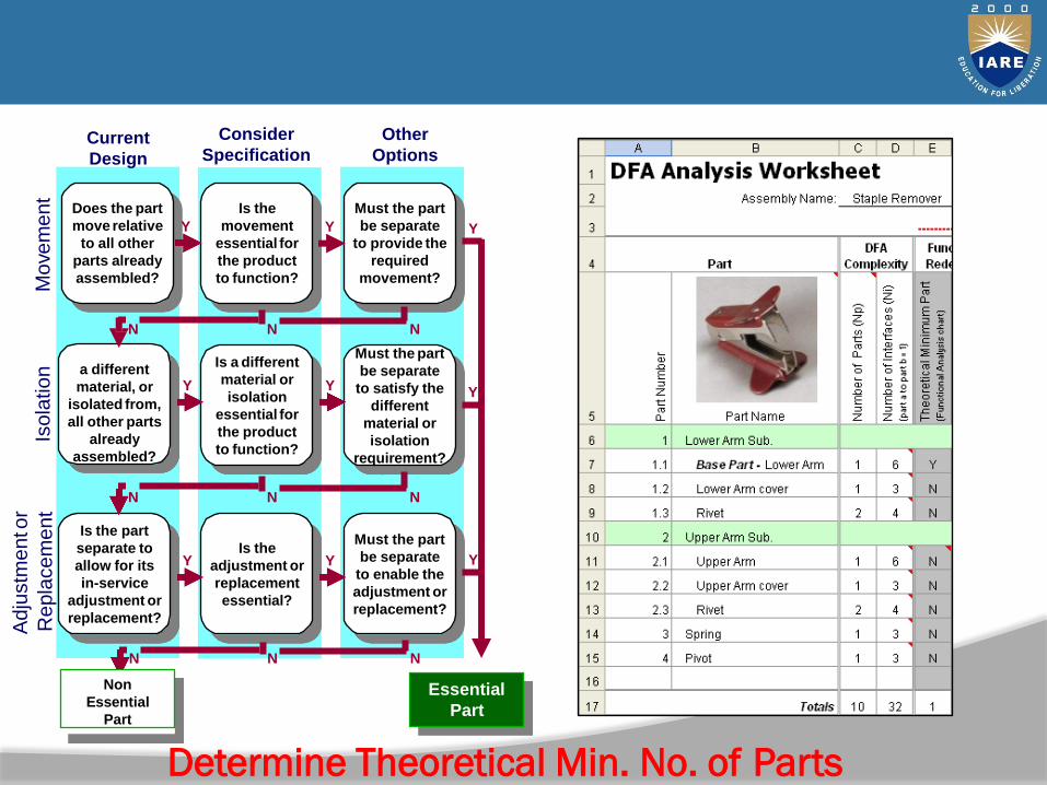
Current
Design
Consider
Specification
Other
Options
Does the part
move relative
to all other
parts already
assembled?
Is the part of
a different
material, or
isolated from,
all other parts
already
assembled?
Is the part
separate to
allow for its
in-service
adjustment or
replacement?
Is the
movement
essential for
the product
to function?
Is a different
material or
isolation
essential for
the product
to function?
Is the
adjustment or
replacement
essential?
Must the part
be separate
to provide the
required
movement?
Must the part
be separate
to satisfy the
different
material or
isolation
requirement?
Must the part
be separate
to enable the
adjustment or
replacement?
Y
Y
Y Y
Y
Y
Essential
Part
N N N
N N N
Y
Y
Y
N N N
Non
Essential
Part
Determine Theoretical Min. No. of Parts
Mo
vem
ent
Iso
latio
nA
dju
stm
en
tor
Re
pla
ce
me
nt

Current Design Consider Specification Other Options
Does the part move
relative to all other
parts already
assembled?
Is the part of a
different material, or
isolated from, all
other parts already
assembled?
Is the part separate
to allow for its in-
service adjustment
or replacement?
Is the movement
essential for the
product to function?
Is a different
material or isolation
essential for the
product to function?
Is the adjustment or
replacement
essential?
Must the part be
separate to provide
the required
movement?
Must the part be
separate to satisfy
the different
material or isolation
requirement?
Y
Y
YMust the part be
Y separate to enable
the adjustment or
replacement?
Y
Y
Essential
Part
N N N
N N N
Y
Y
Y
N N N
Non Essential
Part Functional Analysis
Mo
vem
en
tIs
ola
tio
n
Ad
justm
en
t
or
Rep
lacem
en
t
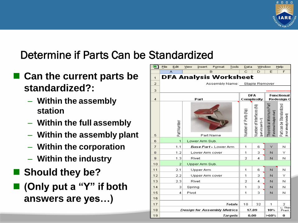
Determine if Parts Can be Standardized
Can the current parts be
standardized?:
– Within the assembly
station
– Within the full assembly
– Within the assembly plant
– Within the corporation
– Within the industry
Should they be?
(Only put a “Y” if both
answers are yes…)
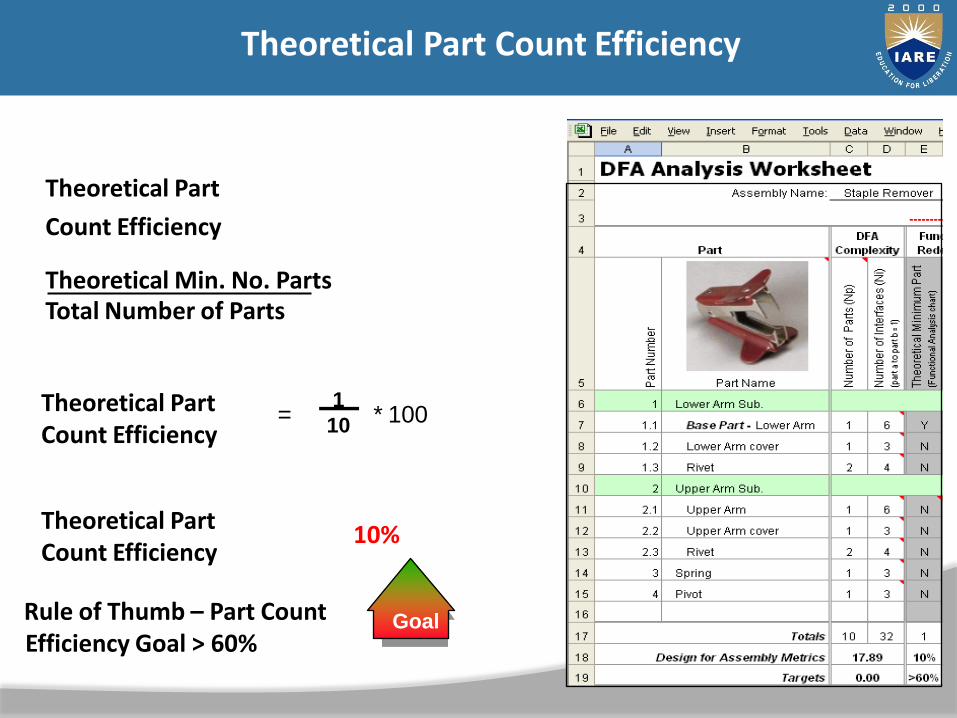
Theoretical Part
Count Efficiency
Theoretical Min. No. PartsTotal Number of Parts
Theoretical Part Count Efficiency
1
10
Theoretical Part Count Efficiency
=
= * 100
= 10%
* 100
GoalRule of Thumb – Part Count Efficiency Goal > 60%
Theoretical Part Count Efficiency

Cummins Inc. metric for assessing complexity of a
product design
Two Factors
Np – Number of parts
Ni – Number of part-to-part interfaces– Multiply the two and take the square root of the
total
Np x Ni
– This is known as the DFA Complexity Factor
DFA Complexity Factor – Definition

Media paper 21.4%
Centertube 3.6%
Endplates (2) 3.0%
Plastisol 2.6%
Inner Seal 4.0%
Spring
Shell
Nutplate
Retainer
Loctite
End Seal
0.9%
31.4%
21.0%
4.8%
0.3%
7.0%
Cost Breakdown
UNIT - V
DESIGN OF MANUAL ASSEMBLY

Team assessment of practical changes
Tradeoffs between part cost and assembly cost
Determine Practical Minimum Part Count

No. PartsPractical Min.
No. Parts
Theoretical Min.
No. Parts
Theoretical Number of
Parts... ‘Blue Sky’
Innovation
Practical & Achievable
Current Design
Creativity & Innovation
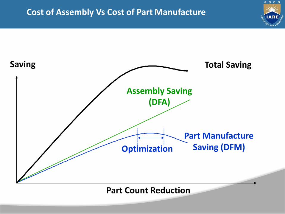
Part Count Reduction
Assembly Saving(DFA)
Part Manufacture Saving (DFM)
Saving
Optimization
Total Saving
Cost of Assembly Vs Cost of Part Manufacture

Risk
HighMediumLow
Short Term
MediumTerm
Implementation
Long Term
Idea Classification

Steps One
& Two
Product Information:
functional requirements
Functional analysis
Identify parts that can be
standardized
Determine part count
efficiencies
Determine your practical part count
Instructions
A study by Ford Motor Co. revealed that threaded fastenerswere the most common cause of warranty repairs
This finding is echoed in more recent survey of automotivemechanics, in which 80% reported finding loose or incorrectfasteners in cars they serviced
Step One
Fasteners
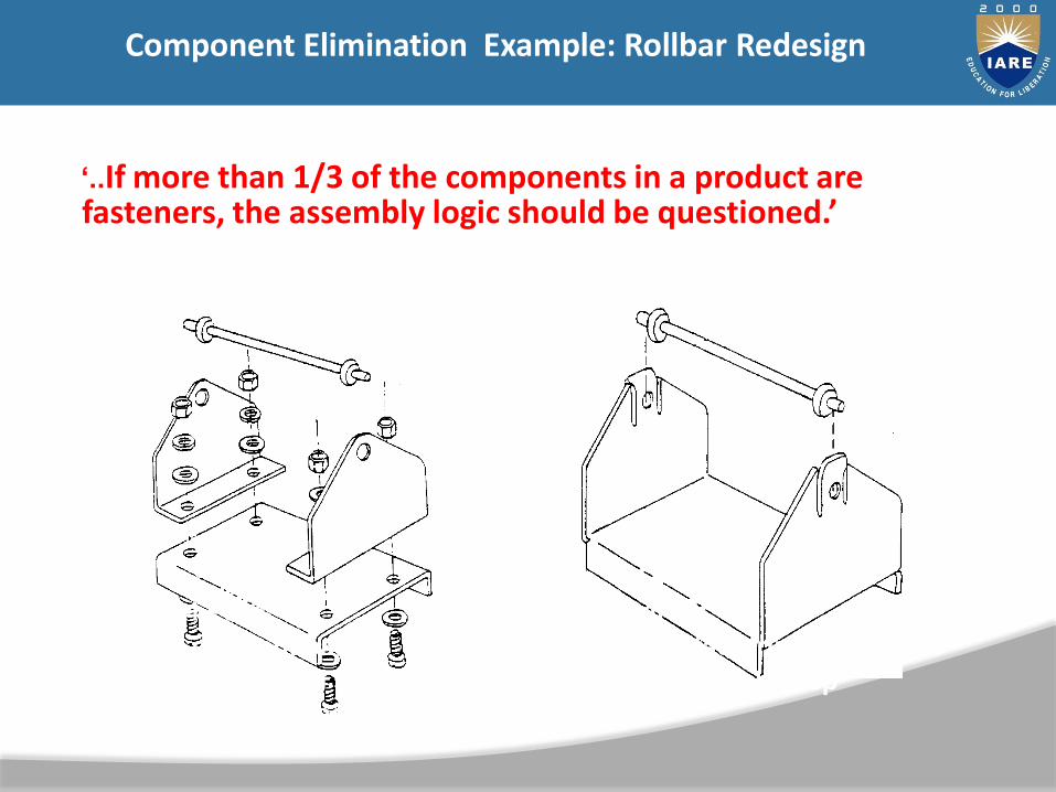
24 Parts
8 different parts
multiple mfg. & assembly
processes necessary
2 Parts
2 Manufacturing processes
one assembly step
„..If more than 1/3 of the components in a product are fasteners, the assembly logic should be questioned.’
Component Elimination Example: Rollbar Redesign

Engine type Number of Components
Number of Fasteners
Percent Fasteners
B Series, 6 Cyl5.9L
1086 436 40%
B Series, 4 Cyl 3.9L
718 331 46%
C Series, 8.3L 1111 486 44%
Fasteners: Cummins Engines
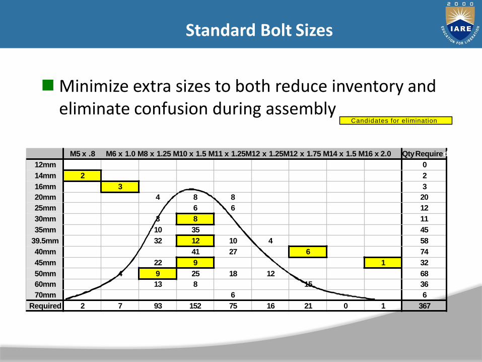
Minimize extra sizes to both reduce inventory and eliminate confusion during assembly
M5 x .8 M6 x 1.0 M8 x 1.25 M10 x 1.5 M11 x 1.25M12 x 1.25M12 x 1.75 M14 x 1.5 M16 x 2.0 QtyRequire
12mm 0
14mm 2 2
16mm 3 3
20mm 4 8 8 20
25mm 6 6 12
30mm 3 8 11
35mm 10 35 45
39.5mm 32 12 10 4 58
40mm 41 27 6 74
45mm 22 9 1 32
50mm 4 9 25 18 12 68
60mm 13 8 15 36
70mm 6 6
Required 2 7 93 152 75 16 21 0 1 367
d
Candidates for elimination
Standard Bolt Sizes

Select the most inexpensive fastening method required
plastic bending
riveting
screwing
snap fit
Fastener Cost

General Design Principles
Self-fastening features
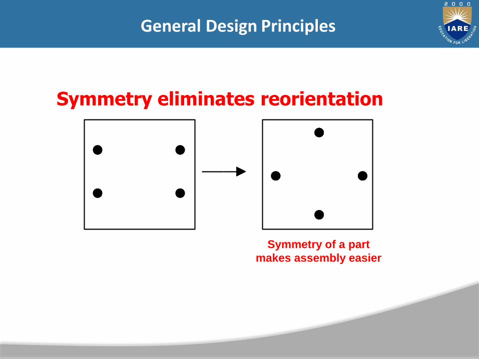
Asymmetric Part Symmetry of a part
makes assembly easier
Symmetry eliminates reorientation
General Design Principles
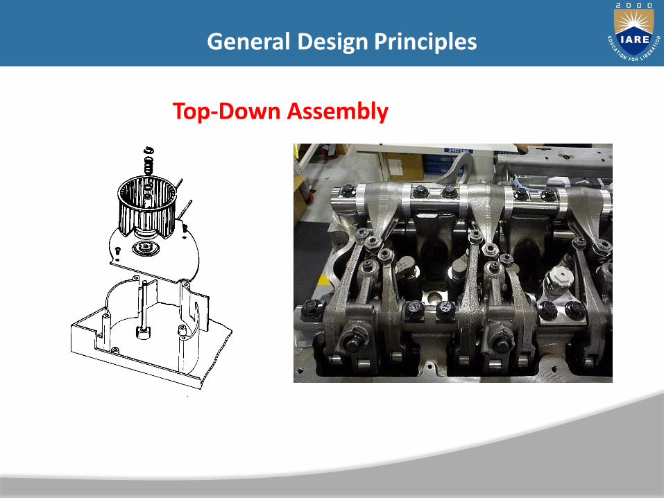
Top-Down Assembly
General Design Principles
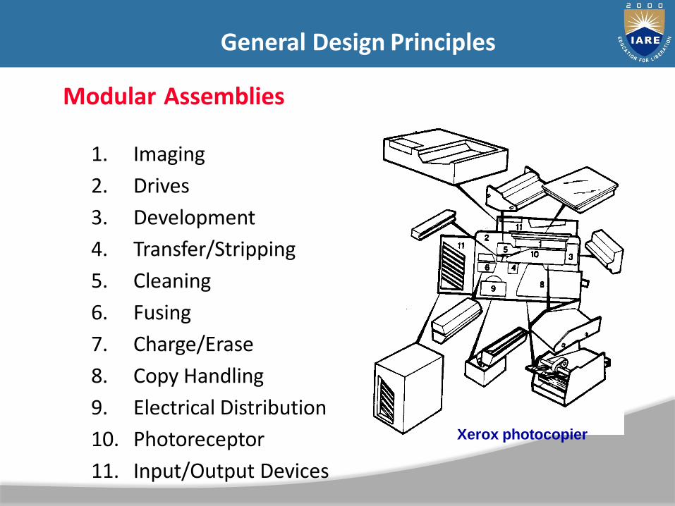
Modular Assemblies
1. Imaging
2. Drives
3. Development
4. Transfer/Stripping
5. Cleaning
6. Fusing
7. Charge/Erase
8. Copy Handling
9. Electrical Distribution
10. Photoreceptor
11. Input/Output Devices
Xerox photocopier
General Design Principles
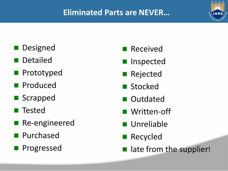
Designed
Detailed
Prototyped
Produced
Scrapped
Tested
Re-engineered
Purchased
Progressed
Received
Inspected
Rejected
Stocked
Outdated
Written-off
Unreliable
Recycled
late from the supplier!
Eliminated Parts are NEVER…
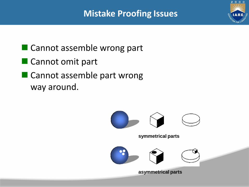
Cannot assemble wrong part
Cannot omit part
Cannot assemble part wrongway around.
symmetrical parts
asymmetrical parts
Mistake Proofing Issues

Handling Time: based on assembly process
and complexity of parts
– How many hands are required?
– Is any grasping assistance needed?
– What is the effect of part symmetry on assembly?
– Is the part easy to align/position?
Quantitative criteria

Size
Thickness
Weight
Fragility
Flexibility
Slipperiness
Stickiness
Necessity for using 1) two hands, 2) optical magnification, or 3) mechanical assistance
Handling Difficulty
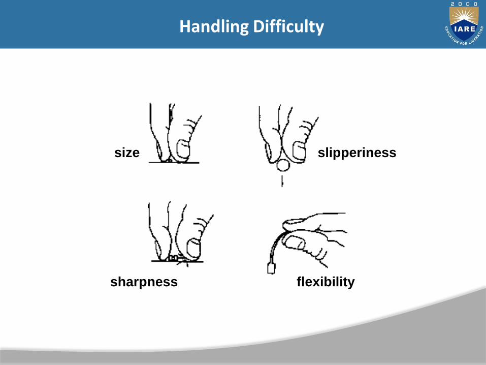
size slipperiness
sharpness flexibility
Handling Difficulty

Eliminate Tangling/Nesting
Insertion timeset on difficulty required
for each component insertion
– Is the part secured immediately upon insertion?
– Is it necessary to hold down part to maintainlocation?
– What type of fastening process is used? (mechanical, thermal, other?)
– Is the part easy to align/position?
Quantitative criteria

Provide self-aligning & self locating parts
Insertion Issues
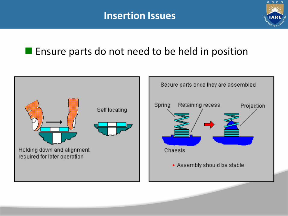
Ensure parts do not need to be held in position
Insertion Issues

Parts are easy to insert.
Provide adequate access & visibility
Insertion Issues

Provide adequate access and visibility
Insertion Issues

Re-orientation (assemble in Z axis)
Screwing, drilling, twisting, riveting, bending, crimping.
Rivet
Eliminate Secondary Operations