Presentation delivered May 12, 2011 - Amazon Web Services
19
Presentation delivered May 12, 2011
Transcript of Presentation delivered May 12, 2011 - Amazon Web Services

Presentation delivered May 12, 2011

Smart Connect: Developing an SMS-Based Communication System
for Health Clinics in Vietnam
Krysta Yousoufian
ABSTRACT
Smart Connect is an SMS-based system that enables rapid information transmission to and from
rural health clinics in developing countries. It is designed to make communication faster and
more direct in countries with geographically isolated health clinics and limited Internet
availability. The Smart Connect system consists of a network of custom-built, low-cost devices
that communicate with a central server to send and receive data via SMS. Here, we describe the
development of a vaccine stock management application to be deployed in Vietnam. In most
respects we were successful in building this complex application on a simple device; however,
severe memory constraints currently prevent the device from being usable in a full-scale
deployment, a problem we are working to mitigate.
1. INTRODUCTION
Rural health facilities in the developing world often have limited communication options. They
may be isolated geographically with limited road access [1], and Internet access is typically out
of reach either for cost or lack of infrastructure. Communication delays can affect critical health
services. In Nicaragua, for example, health workers often do not learn the results of diagnostic
tests on patients‟ blood samples until long after the tests were performed – and often after the
health workers begin administering treatment if they suspect the disease [1]. Cellular phone
networks are rapidly emerging as an alternative medium for rapid data transmission, as they
often extend to considerably more rural areas than Internet coverage.

Smart Connect capitalizes on the availability of cellular phone networks, providing an SMS-
based communication system to transmit information to and from rural health facilities.
Participating facilities receive a “Smart Connect” device with a screen and keypad. The device
accepts user input, displays data, and connects to external sensors. It uses an SMS scheme to
communicate with a country-wide central server connected to a web interface, allowing an
administrator to view data received from the devices and send out messages. The SMS layer is
effectively invisible to users, freeing them to interact with simple menu-based interfaces.
Previous work on Smart Connect has focused on a pilot application in Nicaragua [1]. This
application uses a temperature sensor to monitor a vaccine refrigerator and allows health workers
to record information about patient visits for surveillance reporting. The proposal of a second
pilot application in Vietnam emerged from the Optimize project, an initiative to overhaul the
country‟s system for tracking the vaccine supply chain led by PATH and the World Health
Organization. Vietnam‟s widespread cell phone coverage makes an SMS-based application
feasible.
Here, we report on the development of the Smart Connect Vietnam application. The application
tracks the use and distribution of vaccines throughout the country. The Smart Connect device
stores the quantity of each lot currently in stock or in transit for its health facility. Health workers
can record changes to current stock, which are reported to the server. The server also notifies the
device of incoming shipments containing new lots. Additionally, the device uses an external
temperature sensor to monitor a vaccine refrigerator. If the refrigerator becomes too warm or too
cold, threatening to damage the vaccines, the device will sound an alarm, alert a storekeeper
through SMS, and report the problem to the server. So far the application is in the development
stage, but we expect to begin a field deployment in the coming months.

2. THE SYSTEM
2.1 The Smart Connect Device
We partnered with the nonprofit organization
Inveneo to develop the hardware for the Smart
Connect device (Figure 1). Built to be
economical and rugged, the device features a
simple 20x4 character, black-and-white LCD
display and 3x4 numeric keypad for the user
interface. Along the sides are ports for a USB
cable, AC adaptor, and temperature sensor.
The device runs on the Arduino ATMEGA 1280 microprocessor, which contains 4KB of RAM
and 4KB of non-volatile Electrically Erasable Programmable Read-Only Memory (EEPROM).
The device also contains an additional 1MB of EEPROM external to the microprocessor board.
The firmware is written using the Arduino programming language and integrated development
environment.
2.2 The Server
The SMS server with which the devices communicate is built on RapidSMS, a free and open-
source framework for SMS-based data reporting applications [2]. It provides high-level functions
for processing incoming messages, sending outgoing messages, and creating a web interface to
view or update data. It is also highly flexible, allowing developers to build custom applications.
This “ensur[es] that the software is built specifically for the project, rather than trying to alter the
project to fit the software” [4].
Figure 1. The Smart Connect device with attached temperature sensor.

RapidSMS was designed for applications in low-resource environments like Smart Connect [5].
It has a strong reputation, backed by a number of large-scale deployments in developing
countries [3], and boasts an active developer community for technical support. It is written in
Python and built on the Django web-development framework. It is compatible with a number of
database backends for data storage, and here we use MySQL.
The server is connected to a MultiModem GPRS cellular modem produce by MultiTech
Systems, model MTCBA-G-U-F4. It is one of the modems most widely tested with RapidSMS
and found to be compatible [6].
3. VIETNAM APPLICATION
3.1 Features
On the Smart Connect device, health workers can:
Manage stock
o View the quantities, lots, and expiration dates of vaccines currently in stock
o View the contents (vaccines, lots, and quantities) of incoming shipments and
mark shipments as received
o Update quantities in stock along with a reason for each update: received shipment,
sent shipment, used locally, wastage, expired, or other
o View a log of recent stock updates
Manage temperature
o View the current temperature of an attached sensor
o Receive immediate notification when the temperature becomes unsafe through an
on-screen alert, an audible buzzer, and a text message sent to the storekeeper

o View recent instances where the temperature has become unsafe, including how
long it remained in the unsafe range and the most extreme value it took during
this period
Manage settings
o Change language between Vietnam and English
o Set phone numbers for the server and the storekeeper
o Set GSM band for SIM card
o Change the password for the device
o View the names of “child” locations, health facilities that receive stock shipments
from the current location, and a “parent” location that ships stock to the current
location.
3.2 Workflow
The server administrator uses the server‟s web interface to add and update general information:
Full and abbreviated names of all vaccines in the catalog
Names of all vaccine manufacturers
Names and device phone numbers of all Smart-Connect-enabled locations, plus their
associated locations (the locations they send stock to or receive stock from)
Levels organizing the above locations – e.g. “regional,” “district,” “province”
The server administrator also initializes the chain of vaccine distribution by entering:
Existing lots – their lot number, associated vaccine, manufacturer, and expiration date
Stock shipments sent from the country‟s central distribution point to some Smart-
Connect-enabled facility, including the quantity of each lot the shipment contains

When the server number is first entered on the device and each time the device is powered on,
the device contacts the server to receive and store the following information:
Names of vaccines
Names of manufacturers
Names of locations that send stock to or receive stock from the given location
Several other configuration values (only when server number is first entered)
Figure 2 shows the complete process of
initializing data on the device.
The device also receives and stores the
following updates from the server over time:
Notifications of incoming shipments,
with the quantity of each lot the
shipment contains. The notification
includes each lot‟s number,
expiration date, and manufacturer.
Shipments notifications are either entered by the server admin or received from another
device and forwarded on.
Additions, deletions, and modifications to vaccines, lots, manufacturers, and locations
The device receives and stores the following information from user or sensor input:
Server and storekeeper phone numbers
Changes to vaccine stock: received shipments, sent shipments, local usage, etc.
Figure 2. The process by which data is initialized on the device.

Out of range temperatures
The following data is reported from the device to the server and can be viewed by the server
administrator:
Changes to stock
Recent out-of-range temperatures
Data sent from the device to the server is
bundled into a single daily report. The only
exception is notifications of outgoing
shipments, which are sent immediately to
the server so they can be forwarded to the
recipient more quickly.
Figure 3 shows how data flows between the user, device, and server over time.
4. DEVELOPMENT PROCESS
4.1 Web Mockups
Because the Smart Connect hardware and software were developed in parallel, the software
development began with a virtual prototype built in HTML and JavaScript to explore the UI
appearance and data structures to use. The web prototype proved to be much faster and easier to
develop than the device firmware, as the latter required us to implement low-level functions for
input and display. As a result, the decision to begin with a web prototype had several advantages.
First, it enabled us to build and modify the UI more quickly than on the firmware so we could
focus on optimizing the appearance without being distracted by implementation details. Second,
Figure 3. The process by which data is received and transmitted through the Smart Connect system.

knowing how the UI would look before the firmware
programming began meant we did not waste time rewriting
low-level display functions as the UI design changed. And
third, our partners in Vietnam were able to review the
prototype online and provide feedback earlier.
The first prototype was developed before the appearance of
the screen and keypad were known (Figure 4). Later, the
prototype was modified considerably to represent the
device‟s 20x4 character screen and 3x4 keypad (Figure 5).
Several additional buttons represent two keys pressed
simultaneously.
4.2 Static Firmware Code: UI Development
The basic firmware code we received was minimal and
designed for a much simpler application. It implemented only
the lowest-level behavior, such as responding to user key
presses and sending SMS messages. By contrast, the UI for
the Vietnam application pushes the simple screen and keypad
to their functional limits with scrollable menus and lists, the
ability to navigate forward and backward through menus,
multi-column forms that accept input on each row, and more.
Implementing such functionality was a project in itself. The
first stage of firmware development focused on building the
Figure 5. A second version of the web prototype reflects the appearance of the true screen and keyboard. Additional keypad buttons represent pressing two given keys simultaneously.
Figure 4. The first HTML and JavaScript prototype was designed with a more advanced screen and keypad than the device would eventually have.

UI and data structures with hard-coded data, using no SMS communication – that is, porting the
behavior of the prototype to the device.
4.3 Dynamic Firmware Code: SMS Communication
After developing the static UI, we integrated support for sending and receiving SMS messages.
These capabilities eliminate hard-coded data, with the device dynamically initializing and
updating the vaccine catalog and other information from the server. The device also reports data
to the server and storekeeper. Because the device firmware was mostly written before the server-
side code, we used a Google Voice account as a mock server during development.
The user enters the server number when first setting up the device. Immediately the device sends
a configuration request to the server, which replies with a set of configuration variables, such as
the upper and lower limits of the safe temperature range. The server also sends a second message
with the names of vaccines and manufacturers and a third message with the names of the
device‟s associated locations. Although the server number and configuration variables are stored
in non-volatile memory and only needs to be entered once, the vaccines, manufacturers, and
locations are stored in RAM and erased when the device loses power. Every time the device
regains power it pings the server to resend this data.
A message to or from the server consists of a three-integer header, explained below, followed by
the type of message and any data or parameters. Each SMS also begins with „@‟ and ends with
„!‟ to identify it as a correctly formatted Smart Connect message. Using such a wrapper is a
convention in SMS-based reporting applications.
As an example of a message, the server or device might send the following to acknowledge the
receipt of message #12:

@35 0 1: ACK 12!
where “35 0 1” is the header, “ACK” identifies the message as an acknowledgment message, and
“12” is the ID of the message being acknowledged.
Other messages that involve vaccines, manufacturers, and locations refer to these entities with ID
numbers assigned by the server exclusively for device-server communication. Referring to these
objects by ID number rather than by name allows for more robust, compact messages.
Creating a robust SMS communication system involves many technical challenges. These
include:
Long messages
Transmitting long datasets may require more than the 160 characters each SMS message can
contain. For instance, sending the complete vaccine catalog and manufacturer list to the device at
initialization takes at least two messages. Both the device and server must be able to split long
outgoing messages into several pieces and recombine received messages, and each SMS message
contains a three-integer header for this reason. The first number indicates the message ID. The
devices and server each maintain their own message ID counter and increment it after sending
each message. If a message is split into multiple parts, each part has the same ID. The second
number indicates which part of the larger message this particular SMS message contains, with
numbering beginning at 0. Finally, the third number in the header indicates the total number of
parts for that message.
Each SMS message in a multipart message contains the “@...!” wrapper, a header, and a payload
with as many characters from the longer message as will fit. The message can be truncated mid-
word or mid-integer. Upon receiving an SMS message, the device or server uses the third

number in the header to determine whether it belongs to a multi-part message. If so, the payload
is stored until all the last part is received. Then the complete message is reconstructed by
concatenating the individual parts.
Dropped messages
Both the server and devices must be able to trust that their messages were received. For most
outgoing messages, the sender expects a reply acknowledging receipt. (Clearly recipients do not
acknowledge an acknowledgment message, which would start an infinite chain of
acknowledgments!) Only one acknowledgment is sent for multi-part messages, after the entire
message has been received.
If no acknowledgment is received within ten minutes, the message is resent. If there is still no
reply ten minutes later, it is resent again. If there is no reply even after the third attempt, the
message is deemed a failure and the message is not resent. If a device sent the message, the
device enters an alert state, displaying the message “Unknown Error / No response from svr.” If
the server sent the message, it keeps the message in the database and flags it as failed, which
could be used to alert the server administrator to a technical problem or unresponsive device.
In the case that the acknowledgment message was dropped, rather than the original message, a
recipient may receive the same message twice. Messages should therefore be approximately
idempotent: receiving the same message twice either has no effect at all (e.g. updating the
expiration date of a lot twice to the same value) or a relatively benign effect (e.g. sending a
shipment notification twice: the device will think it has two incoming shipments, but the user can
mark one of the shipments as received with no lots).

Once a day the device and server also check for any pieces of a multi-part message that have
been stored for more than 24 hours while waiting for the rest of the message to come in.
Ordinarily no such message should be found, but if so the parts are deleted to free memory and
prevent confusion if that message‟s ID number is later reused for another message.
Spacing messages apart
The GSM module on the device can only handle one incoming or outgoing SMS message at a
time. It is prone to crash when two messages are sent or received too rapidly, which is especially
a problem for multi-part messages. Outgoing SMS messages from the device are stored in a
queue, with each message in the queue only sent after the GSM module has finished processing
the previous message. For incoming SMS messages, the server waits ten seconds between
sending each message to the device. This time interval was found to give the device enough time
to receive and process each message before the next arrives.
4.4 Server Code
The server-side application consists of two components: 1) the code to automatically handle
incoming SMS messages and 2) the web interface through which an administrator views and
updates data. The current focus was on the former. Django, the framework on which RapidSMS
is built, offers a built-in admin web interface for viewing and updating database tables. We used
that as the extent of the user interface at this point.
The server‟s message handling logic is similar to that of the device. When an SMS message
arrives, the server first parses it into the header and payload and stores multi-part messages until
all parts have arrived. The complete message is processed according to the message type.
Depending on this type, the server may store data from the message, send data out, or both. It
may also reply with a message acknowledgment.
Each active device is expected to report its recent activity to the server daily. Once a day, the
server should check for devices that missed their last report. How it should handle unresponsive
devices has yet to be determined. Depending on the use scenarios for the web interface, the
server might display an alert on the web UI or notify the server admin of the unresponsive device
via SMS. The device can also send a report for a given day‟s activity upon request, so the server
might try to obtain the missing report before alerting the admin to the problem.
After developing the device and server code independently, we brought the two halves together
with surprising ease. Each had been written according to the same message scheme, with
common acknowledgment systems, message headers, and formats for each type of message. In
theory there was no reason for incompatibility. Even so, we expected unforeseen issues and were
pleased that the device and server quickly began to communicate successfully.
5. CHALLENGES
Many development challenges were the result of working with a low-resource device in a low-
resource environment. The Vietnam application is much more complex and resource-intensive
than the types of applications for which Smart Connect was designed.
The greatest problem we face is a memory shortage. The device needs to store a catalog of up to
10 vaccines, up to seven lots per vaccine at a time, up to 40 locations, several manufacturers, and
several shipments. EEPROM is difficult to use for complex and changing data structures, so this
data is currently stored in RAM. Unfortunately, the 4KB of RAM on the device is nowhere near
enough for these data quantities. During our testing the device ran out of memory with a tiny
dataset of just six vaccines, four manufacturers, four locations, and one shipment of 1-2 lots per
vaccine. The only apparent solution is to store most data in EEPROM, only loading small
amounts into RAM at a time.
EEPROM is also the solution to another problem: data loss. Data stored in RAM is erased every
time the device loses power. This is a significant problem in a country where power outages can
occur on a daily basis, especially if the application only reports data to the server only once per
day. Currently the vaccine catalog, manufacturers, and locations are resent from the server every
time the device regains power, but the lots and quantities in stock are not. Storing data in non-
volatile RAM will preserve it against power failures.
Another constraint of the device is the 3 x 4 keypad. We originally envisioned being able to enter
alphabetic input on the device, such as names of other locations or reasons for stock updates. The
application was revised so some alphabetic data, such as names of vaccines and locations, was
sent from the server while nonessential alphabetic data was eliminated altogether. The * and #
keys were used for scrolling up and down through a menu. We used double-key combinations for
other navigational commands, namely Enter to advance to the next panel (0 and #), Back to go to
the previous panel (0 and *), and Backspace to erase input (8 and *). On discovering that the
firmware could not detect two keys pressed simultaneously, we added a counter to determine
how close in time two keys were pressed. Drumming the two keys so they are pressed at
distinctly different times but only a fraction of a second apart is interpreted as pressing them
simultaneously.
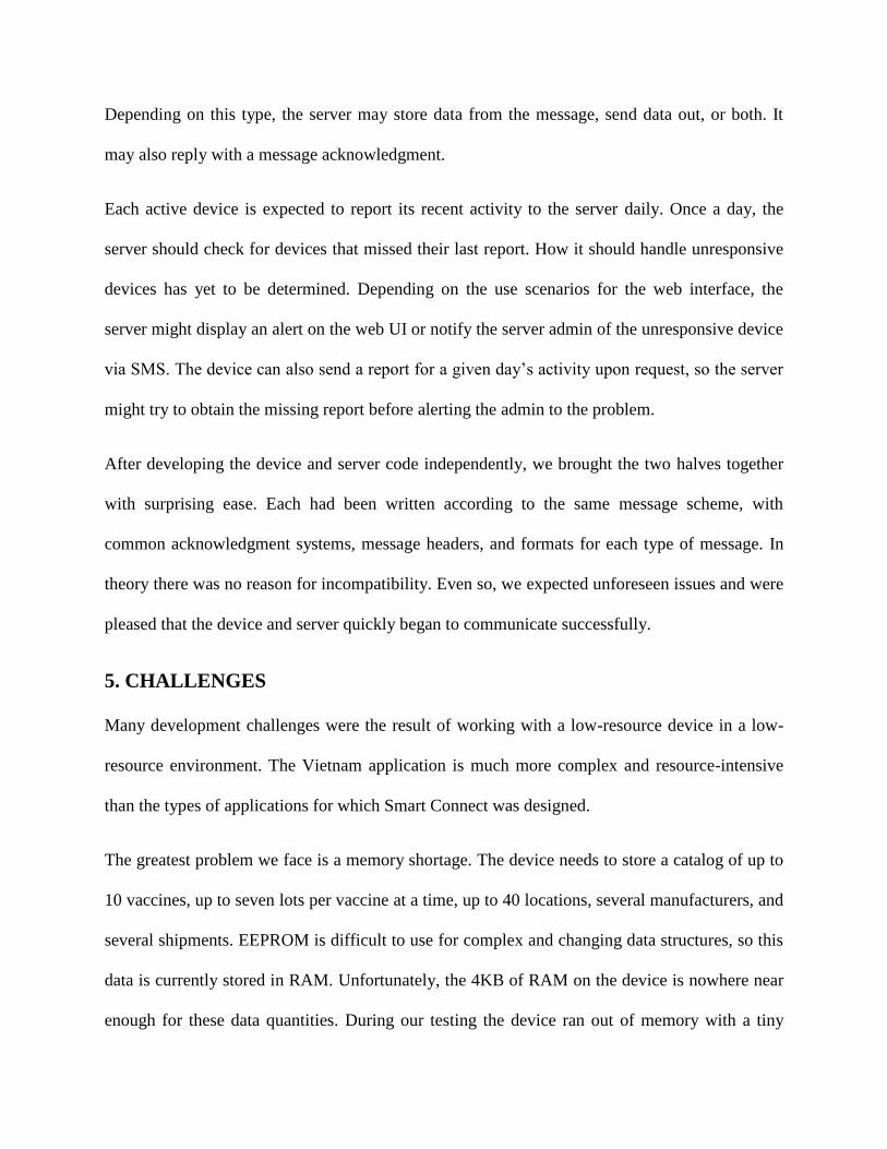
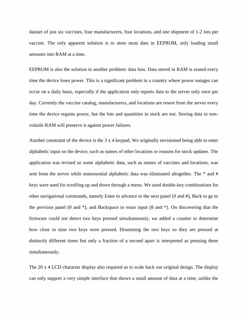
The 20 x 4 LCD character display also required us to scale back our original design. The display
can only support a very simple interface that shows a small amount of data at a time, unlike the
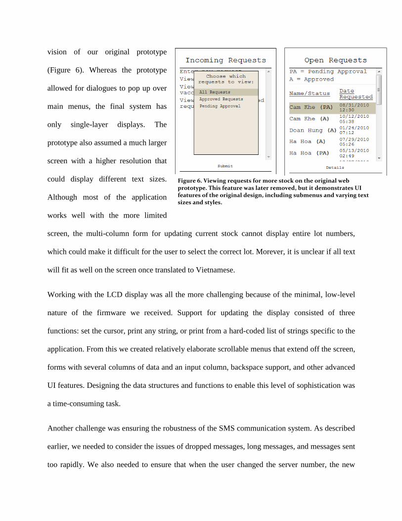
vision of our original prototype
(Figure 6). Whereas the prototype
allowed for dialogues to pop up over
main menus, the final system has
only single-layer displays. The
prototype also assumed a much larger
screen with a higher resolution that
could display different text sizes.
Although most of the application
works well with the more limited
screen, the multi-column form for updating current stock cannot display entire lot numbers,
which could make it difficult for the user to select the correct lot. Morever, it is unclear if all text
will fit as well on the screen once translated to Vietnamese.
Working with the LCD display was all the more challenging because of the minimal, low-level
nature of the firmware we received. Support for updating the display consisted of three
functions: set the cursor, print any string, or print from a hard-coded list of strings specific to the
application. From this we created relatively elaborate scrollable menus that extend off the screen,
forms with several columns of data and an input column, backspace support, and other advanced
UI features. Designing the data structures and functions to enable this level of sophistication was
a time-consuming task.
Another challenge was ensuring the robustness of the SMS communication system. As described
earlier, we needed to consider the issues of dropped messages, long messages, and messages sent
too rapidly. We also needed to ensure that when the user changed the server number, the new
Figure 6. Viewing requests for more stock on the original web prototype. This feature was later removed, but it demonstrates UI features of the original design, including submenus and varying text sizes and styles.

number would be remembered but would not overwrite the old number in EEPROM until the
new server had confirmed the number was correct by sending the correct response.
Lastly, we considered security vulnerabilities in the system. When receiving SMS messages, the
device ignores any messages not from the server, and the server ignores messages not from a
known device phone number. A user can change the server number on the device, but as
described previously the new number will not be saved until the server sends the correct
configuration reply. If a user modifies the storekeeper number, the change is saved
automatically, but the old storekeeper is notified of the change. The device also requires a
password to log in, but currently the password is stored only in RAM and not EEPROM.
Although the password can be changed, it resets to the default if the device is unplugged. A
simple modification to store the password in EEPROM would improve security, but there should
be a way for the server admin to remotely reset a device‟s password in case it is lost.
6. RESULTS
Our application meets most requirements and standards. We built a relatively sophisticated user
interface that matches the vision of the prototype, we implemented the required features, and the
device communicates successfully with the server. In those respects we have accomplished a
great deal.
However, the project cannot yet be called a success. The unforeseen and severe memory shortage
currently leaves the system unusable for practical purposes. The application works so long as the
data set is sufficiently small, but it fails at the level of a realistic deployment. Fortunately, we
expect that storing data primarily in EEPROM will resolve these problems. We are currently
working to incorporate EEPROM as quickly as possible.

7. FUTURE WORK
The EEPROM work is our top priority and the primary issue blocking a field test. Several
smaller development tasks on the Smart Connect device also remain, such as supporting longer
lot numbers that can contain alphabetic characters. There is considerable work to be done on the
server application, as our priority was to complete the device application first. The largest server-
side task is building the web UI, which also needs to be integrated with the SMS-handling code
so that entering or changing data (e.g. new shipments) will force updates to be sent to the
devices. Other unfinished work items include handling daily reports from the devices and
checking for and responding to devices that missed their last daily report.
8. CONCLUSIONS
Our application demonstrates both the potential and limitations of the Smart Connect device. We
have shown that with enough development time, this low-cost system built from simple hardware
can support a complex application in nearly every respect. The notable exception is the memory
issue, which currently renders the application virtually unusable. We expect to be able to
overcome this limitation – but not without considerable extra time investment in an application
that has already been challenging and time-consuming to develop. The device was originally
envisioned as part of much simpler reporting systems, such as that deployed in Nicaragua. While
we hope to find that Smart Connect is capable of handling the full Vietnam application, our
experience is that it is best suited for simpler applications.
ACKNOWLEDGEMENTS
I would like to thank Richard Anderson, Nell O‟Rourke, and Rohit Chaudhri for their help and
support with this project.

REFERENCES [1] Anderson, R., Blantz, E. Lubinski, D., O‟Rourke, E., Summer, M., and Yousoufian, K., “Smart Connect:
Last mile data connectivity for rural health facilities,” 4th
ACM Workshop on Networked Systems for
Developing Regions (NSDR), June 2010
[2] RapidSMS, http://www.rapidsms.org/
[3] RapidSMS: Case Studies, http://www.rapidsms.org/case-studies/
[4] RapidSMS: FAQ, http://www.rapidsms.org/ecosystem/faq/
[5] RapidSMS: Overview, http://www.rapidsms.org/overview/
[6] Supported Devices, https://github.com/adammck/pygsm/wiki/