PREparing SEcuRe VEhicle-to-X Communication Systems · SCORE@F TEST SITE DESCRIPTION ... Module...
66
08/01/2014 IST-269994 1 PREparing SEcuRe VEhicle-to-X Communication Systems Deliverable 3.1.2 Joint FOT test results V2X Project: PRESERVE Project Number: IST-269994 Deliverable: D3.1.2 Title: Joint FOT test results Version: v1.0 Confidentiality: Public Editors: Brigitte Lonc (Renault) Date: 2014-01-02 Part of the Seventh Framework Programme Funded by the EC – DG INFSO
-
Upload
duongthuan -
Category
Documents
-
view
216 -
download
0
Transcript of PREparing SEcuRe VEhicle-to-X Communication Systems · SCORE@F TEST SITE DESCRIPTION ... Module...
08/01/2014 IST-269994 1
PREparing SEcuRe VEhicle-to-X Communication Systems
Deliverable 3.1.2
Joint FOT test results V2X
Project: PRESERVE
Project Number: IST-269994
Deliverable: D3.1.2
Title: Joint FOT test results
Version: v1.0
Confidentiality: Public
Editors: Brigitte Lonc (Renault)
Date: 2014-01-02
Part of the Seventh Framework
Programme
Funded by the EC – DG INFSO
08/01/2014 IST-269994 2
Document History
Version Status Author Date
0.1 Creation of document, section 2 and 3 and glossary Brigitte Lonc (Renault) 2013-09-26
0.2 Joint FOT results and analysis Djurre Broekhuis (UT) 2013-10-17
0.3 added Score@F test beds description (OBU, RSU) B. Lonc, Rim Moalla 2013-10-18
0.4 added introduction and section 3.4 Attacker tool, small corrections in test result
B. Lonc, Marcello Lagana (KTH), Djurre Broekhuis (UT)
2013-11-01
1.0 completion and review of deliverable D3.1.2 B. Lonc, J. Petit 2014-01-02

08/01/2014 IST-269994 3
Contents CONTENTS ...................................................................................................................... 3!GLOSSARY ...................................................................................................................... 4!1! INTRODUCTION ...................................................................................................... 10!2! TEST METHODOLOGY ........................................................................................... 11!
2.1! MOTIVATION OF SECURITY FOT METHODOLOGY .................................................... 11!2.2! TESTS OVERVIEW ................................................................................................ 11!2.3! FESTA OVERVIEW .............................................................................................. 15!2.4! FUNCTION IDENTIFICATION & DESCRIPTION .......................................................... 16!2.5! USE CASES ......................................................................................................... 17!
2.5.1! Use Cases Overview ................................................................................... 17!2.5.2! Use Cases Details ....................................................................................... 20!
2.6! RESEARCH QUESTIONS & HYPOTHESIS ................................................................ 39!2.7! PERFORMANCE INDICATORS & STUDY DESIGN ...................................................... 39!2.8! MEASURES & SENSORS ....................................................................................... 41!2.9! DATA ACQUISITION ............................................................................................... 48!
2.9.1! Logging in the VSS ..................................................................................... 48!2.9.2! Logging in the security infrastructure .......................................................... 50!
2.10! DATA ANALYSIS .................................................................................................. 51!2.11! IMPACT ASSESSMENT AND SOCIO-ECONOMIC COST BENEFIT ANALYSIS (TASK 3300 AND WP5) .................................................................................................................... 51!
3! SCORE@F TEST SITE DESCRIPTION ................................................................... 51!3.1! JOINT FOT TEST BEDS DESCRIPTION (OBU, RSU) ................................................ 55!3.2! ATTACKER TEST TOOL .......................................................................................... 57!
4! TEST RESULTS ....................................................................................................... 58!4.1! PERFORMANCE ANALYSIS .................................................................................... 59!
5! CONCLUSION .......................................................................................................... 65!6! BIBLIOGRAPHY ...................................................................................................... 66!
08/01/2014 IST-269994 4
Glossary Abbreviation Synonyms Description Details
API Application Programming
Interface
ASIC Application Specific Integrated
Circuit
an integrated circuit (IC) customized for a particular use
ASN.1 Abstract Syntax Notation One
AU Application Unit Hardware unit in an ITS station running the ITS applications
CA Certificate Authority
CAM Cooperative Awareness Message
CAMs are sent by vehicles multiple times a second (typically up to 10 Hz), they are broadcasted unencrypted over a single-hop and thus receivable by any receiver within range. They contain the vehicle's current position and speed, along with information such as steering wheel orientation, brake state, and vehicle length and width.
CAN Controller Area Network
In-vehicle bus system
CCM Communication Control Module
Module originating from the EVITA project
CCU Communication & Control Unit
Hardware unit in an ITS station running the communication stack
CE Consumer Electronics
Electronic devices like smartphone or MP3 player of the vehicle driver or a passenger
CL Convergence Layer
PRESERVE module that connects the communication stack to the PRESERVE Vehicle Security Subsystem (VSS)
CPU Central Processing Unit
CRC Cyclic Redundancy Code
CRS Cryptographic Services
Module originating from the EVITA project

08/01/2014 IST-269994 5
DoS Denial of Service
DENM DNM Decentralized Environmental
Notification Message
A DENM transmission is triggered by a cooperative road hazard warning application, providing information to other ITS stations about a specific driving environment event or traffic event. The ITS station that receives the DENM is able to provide appropriate HMI information to the end user, who makes use of these information or takes actions in its driving and traveling.
EAM Entity Authentication
Module
Module originating from the EVITA project
ECC Elliptic Curve Cryptography
ECU Electronic Control Unit
EJFT Extended joint FOT
ASIC based VSS implementation joint FOT
FPGA Field Programmable
Gate Array
Integrated Circuit designed to be configured by customer of designer after manufacturing
FOT Field Operational Test
G5A ITS road safety communication
(802.11p)
Frequency band between 5.875 GHz and 5.905 GHz - reserved for ITS road safety communication
G5B ITS non-safety communication
(802.11p)
Frequency band between 5.855 GHz and 5.875 GHz - reserved for ITS road non-safety communication
G5C C-WLAN 5GHz WLAN communication
(802.11a)
GNSS GPS Global Navigation Satellite System
Generic term for an Global navigation satellite system (GPS, GLONAS, Galileo)
HMI Human-Machine Interface
HSM Hardware Security Module
HU Head-Unit
I2V I2C Infrastructure-to- Communication between
08/01/2014 IST-269994 6
Vehicle infrastructure components like roadside units and vehicles
I2I Infrastructure-to-Infrastructure
Communication between multiple infrastructure components like roadside units
ICRW Intersection Collision Risk
Warning
ICS ITS Central Station ITS station in a central ITS sub-system
IFT1 Internal FOT trial 1 FPGA based VSS implementation FOT
IFT2 Internal FOT trial 2 ASIC based VSS implementation FOT
ILP Inter Layer Proxy Component introduced by the SeVeCom project, that captures and allows modification of messages between different layers of a communication stack
IMT GSM, GPRS, UMTS
Public cellular services (2G, 3G,
...)
IPR Intellectual Property Right
ITS Intelligent Transportation
Systems
Intelligent Transport Systems (ITS) are systems to support transportation of goods and humans with information and communication technologies in order to efficiently and safely use the transport infrastructure and transport means (cars, trains, planes, ships).
ITS-S ITS Station Generic term for any ITS station like vehicle station, roadside unit, ...
ITMM ID & Trust Management
Module
Module originating from SeVeCom project
IVC ITSC, ITS Commu-nications
Inter-Vehicle Communication
Combination of V2V and V2I
IVS OBU ITS Vehicle Station
The term "vehicle" can also be used within PRESERVE
JFT Joint FOT trial with Score@F (FPGA
based)
LCRW Longitudinal
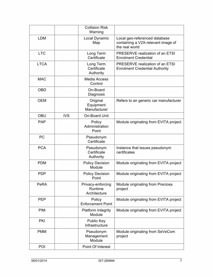
08/01/2014 IST-269994 7
Collision Risk Warning
LDM Local Dynamic Map
Local geo-referenced database containing a V2X-relevant image of the real world
LTC Long Term Certificate
PRESERVE realization of an ETSI Enrolment Credential
LTCA Long Term Certificate Authority
PRESERVE realization of an ETSI Enrolment Credential Authority
MAC Media Access Control
OBD On-Board Diagnosis
OEM Original Equipment
Manufacturer
Refers to an generic car manufacturer
OBU IVS On-Board Unit PAP Policy
Administration Point
Module originating from EVITA project
PC Pseudonym Certificate
PCA Pseudonym Certificate Authority
Instance that issues pseudonym certificates
PDM Policy Decision Module
Module originating from EVITA project
PDP Policy Decision Point
Module originating from EVITA project
PeRA Privacy-enforcing Runtime
Architecture
Module originating from Preciosa project
PEP Policy Enforcement Point
Module originating from EVITA project
PIM Platform Integrity Module
Module originating from EVITA project
PKI Public Key Infrastructure
PMM Pseudonym Management
Module
Module originating from SeVeCom project
POI Point Of Interest

08/01/2014 IST-269994 8
QoS Quality of Service
RHS Road Hazard Signalling
RP Reference Point Reference points are defined in order to describe links (e.g. communication links) between system entities of ITS
RSU IRS, ITS Roadside
Station
Roadside Unit
SAP Service Access Point
SCM Secure Communication
Module
Module originating from SeVeCom project
SEP Security Event Processor
SSM Secure Storage Module
Module originating from EVITA project
TCU Telematics Control Unit
TOC Transportation Operation Center
TPM Trusted Platform Module
UML Unified Modeling Language
UTC Universal Time Coordinated
V2I C2I Vehicle-to-Infrastructure
Direct vehicle to roadside infrastructure communication using a wireless local area network
V2V C2C Vehicle-to-Vehicle Direct vehicle(s) to vehicle(s) communication using a wireless local area network
V2X C2X Vehicle-to-Vehicle (V2V) and/or Vehicle-to-
Infrastructure (V2I)
VIA Visitor Internet Access
VIN Vehicle Identification
Number
Unique serial number of a vehicle
08/01/2014 IST-269994 9
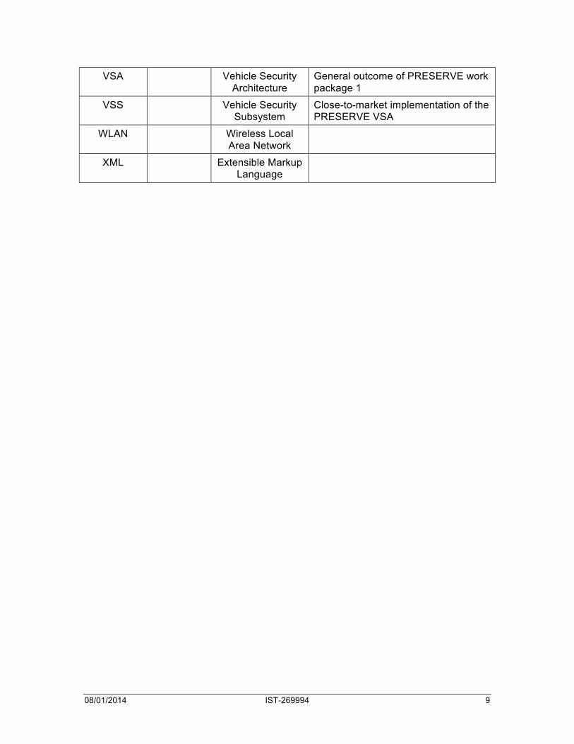
VSA Vehicle Security Architecture
General outcome of PRESERVE work package 1
VSS Vehicle Security Subsystem
Close-to-market implementation of the PRESERVE VSA
WLAN Wireless Local Area Network
XML Extensible Markup Language

08/01/2014 IST-269994 10
1 Introduction This deliverable D3.1.2 presents the results of the assessment tests of PRESERVE V2X Security Subsystem (VSS kit1) done jointly with the French FOT for Cooperative Systems (Score@F). Score@F is part of the Drive CX2 project which includes six national test sites and one interoperability test site. See ref [8], [9].
A MoU was signed between PRESERVE and Score@F to cover the integration of PRESERVE VSS SW-only version into the Score@F project in July 2013. Due to the lack of cooperation agreement with all partners, the FPGA-based VSS was not tested within the Score@F FOT but was functionally tested in the Internal FOT Trial1 at University of Twente.
This deliverable presents the results of functional testing and the analysis of measurements done on the Joint FOT Trial1 with Score@F in the period from July 2012 to end September 2013.
Section 2 presents the assessment plan for PRESERVE VSS implementation based on the FESTA test methodology. This section details the steps of the test methodology, the uses cases and research questions (regarding the challenges of PRESERVE security and privacy solutions for V2X communications), the performance indicators and measurement procedures used to evaluate the PRESERVE VSS implementation.
Section 2 integrates the specification of a list of test cases that can be used in various trials during the project duration. These test descriptions include functional tests as well as security tests (attack scenarios). It was initially prepared as an individual report, named Testing Handbook (ref [7]) for dissemination to other projects (e.g. FOTNET, Drive C2X).
Section 3 presents Score@F test site used for PRESERVE trials: the test environment and set-up, the test purpose and main functions and operational requirements tested during the concerned field-testing activities. A test tool for attack scenarios was developed and used during the joint test sessions and is presented in section 3.4.
Section 4 presents the evaluation of measurements from the Joint FOT with Score@F. This deliverable D3.1.2 includes conclusions, based on measurements done during the joint test sessions conducted on Score@F platforms (ITS-S Vehicle stations and ITS Roadside Stations).
This deliverable includes a report of problems experienced during this first joint FOT Trial1 (JFOT1) and proposes solutions for solving them for next trials (see section 5).

08/01/2014 IST-269994 11
2 Test Methodology
2.1 Motivation of security FOT methodology The PRESERVE project foresees a number of Field Operational Testing activities as laid out in the description of work and especially the description of WP3 “Field Operational Tests”. WP3 foresees four different tests to be conducted: an FPGA-only test (internal trial 1), a joint test of PRESERVE VSS kit1 with Score@F, an internal test with ASICs (trial 2), and a joint trial with integration of the PRESERVE VSS into vehicles of another FOT project (extended joint trial). The overall purpose of these tests is to demonstrate the functionality of the system under realistic deployment conditions on the one hand, and to gain operational measurements (esp. performance measurements) on the other. In the end it should be possible to give a clear statement about the suitability of the VSS for a larger-scale deployment in pilot tests and to outline a roadmap for product deployment.
It needs to be stressed that PRESERVE focuses strictly on the security functions of a cooperative ITS based on G5A-type of communication. These functions are normally not visible to others and will – in the ideal case – have no negative effect on the functionality of applications or on vehicular traffic. A deviation from normal operation should only occur in case of malicious (or faulty) behaviour of system entities. This implies that the nature of our tests will be different from other FOT activities that typically aim at assessing functions directly related to drivers or traffic.
Nevertheless, our testing approach at least roughly follows the FESTA approach as described in the FESTA Handbook Rev 4 from Sept. 2011. It is the purpose of section 2 to describe our testing approach and our adaptations. It should serve as a handbook for preparation, conduction, and evaluation of the PRESERVE tests (see ref [7]).
2.2 Tests Overview PRESERVE foresees three rounds of testing. In this Section we give an overview of these tests. In deviation from the original plan stated in the description of work, we re-order activities to some extent. This is due to the fact that the original joint trial was originally planned for M31 to M42, i.e., it would start mid 2013 and run until mid 2014. We planned for this late conduction of a joint test as we wanted to integrate the PRESERVE ASIC-based Hardware Security Module into the testing. However, even though we run on a tight design and production schedule, this ASIC will not be available in sufficient quantities before mid 2013.
This does not align with FOT activities of potential partner FOTs. Many of these have a shorter project duration and plan to conduct the majority of testing activities in 2012. We had in-detail discussions with the French Score@F (which also participates in the DRIVE C2X activities) and came to the conclusion, that a testing opportunity in the second half of 2013 cannot be foreseen.
So we agreed on an alternative strategy that foresees a joint test in 2012. Here, we will equip a limited number of cars (up to 30) with an FPGA-based (functional equivalent) version of the PRESERVE HSM and conduct joint tests to primarily assess the functionality of the PRESERVE VSS and to demonstrate that the PRESERVE VSS.
We distinguish three different load scenarios:

08/01/2014 IST-269994 12
1. Low Load: up to 5 OBUs in communication range. This density will be achieved in lab tests and will primarily be used to test correct functionality.
2. Medium Load: up to 30 OBUs in communication range. This is a typical load that will occur even in early phases of deployment and especially in many FOTs and Pilot deployments.
3. High Load: by having more than 50 OBUs in communication range and letting them communicate with increased message rates (10 Hz, 20 Hz, 30 Hz, above 30 Hz), we can emulate very high load scenarios that will reach channel capacity limits. (Robert Schmidt 2011) discusses that increasing packet rates is to some extent a valid approach to emulate a higher number of nodes in a wireless communication environment. Still, the comparatively high number of OBUs is required to have realistic broadcast collision behavior. However, we also acknowledge that this approach is looking only at control channel communication. We assume that communication patterns on the service channels will be different from control channel communication, including higher number of unicast and/or IP-based communication that will put less stress on the VSS compared to broadcast messages with asymmetric signatures.
The four tests planned include:
1. Internal Test (Internal FOT Trial 1, IFT1): This is an internal test of the first (FPGA-based) VSS Kit. Its aim is to perform lab testing to verify overall functionality and to benchmark internal timings in less-loaded environments. Furthermore, an integration with in-vehicle components using EVITA mechanisms will demonstrate that integration is possible.
2. Joint Test with Score@F (Joint FOT Trial, JFT): This test will integrate the (FPGA-based) VSS Kit 1 in the Score@F FOT platform. The primary purpose is to verify that the VSS is fully functional and can be integrated into a fully functional V2X environment. The second purpose is to conduct performance measurements in a medium-loaded environment with up to 30 vehicles and including mobility.
3. Hybrid Test (Internal FOT Trial 2, IFT2): This test serves as a performance verification of the (ASIC-based) VSS Kit 2 in a high-load environment with a high number of OBUs (above 60) but without mobility.
4. Extended Joint FOT Trial (EJFT): If there is an opportunity to conduct additional joint tests in 2013 and 2014 with Score@F or another FOT or pilot deployment project, this offers the opportunity to test the (ASIC-based) VSS Kit 2 in a high-load environment with a high number of OBUs and mobility. EJFT description is not included in this version of testing report.

08/01/2014 IST-269994 13
Figure 2-1 shows an adjusted timeplan that illustrates the duration and time of these tests.

08/01/2014 IST-269994 14
Figure 2-1: Adjusted PRESERVE Timeplan (Amendment 2)

08/01/2014 IST-269994 15
2.3 FESTA Overview
FESTA Handbook Introduction
2
copy of the figure is provided in the beginning of each chapter highlighting which step of the FOT [FW] Chain is described in the current chapter. The FOT Implementation Plan takes up all the steps and integrates them into one big table which can be used as a reference when actually carrying out an FOT [FW].
Figure 1.1: The steps that typically have to be considered when conducting an FOT. The large arrows indicate the time line.
In order to make the picture more complete a horizontal bar should be added on top of the diagram that in principle summarises the context in which the FOT [FW] is supposed to take place. For instance, the choice of a function[FW] to be tested implies that there is either a problem that is to be addressed and that the chosen function[FW] is defined to solve the problem or that a policy objective is stated and that the function[FW] tested can be used to reach the objective. An FOT [FW] can always be related to a wider view on the exercise than is defined by just a description of the function[FW] to be tested.
This can be summarised as the first steps, which include setting up a goal for the study and selecting a suitable research team, and also the last steps that include an overall analysis of the systems[FW] and functions[FW] tested and the socio-economic impact assessment, dealing with the more general aspects of an FOT [FW] and with aggregation of the results. The further down on FOT [FW] Chain V-Shape the steps are located, the more they focus on aspects with a high level of detail, like which performance indicators[FW] to choose, or how to store the data in a database. The ethical and legal issues have the strongest impact on those high-level aspects, where the actual contact with the participants and the data handling takes place.
Context
Using
Figure 2-2: FESTA Methodology (from (FESTA / FOT-NET 2011) )
As you can see, the FESTA / FOT-NET approach to field-operational testing provides a generic framework for conducting scientific tests of systems. While the handbook is very specific to driving tests involving end-users, the framework is nevertheless a useful guidance for the more technical tests that PRESERVE is going to conduct.
We need to stress one thing here: first, the PRESERVE VSS is not meant to interfere with actual system operation, i.e., ideally security operations are transparent to applications and facilities. While it introduces extra payload and delays, applications and facilities should not be affected other than in case of attacks. The same is true for drivers. We aim for an automated security system that does not require intervention of drivers, as such intervention could lead to distractions and would typically require a substantial level of security expertise.
Due to this, our testing serves different purposes. We want to investigate and demonstrate that the PRESERVE VSS can be integrated into a large V2X network without negatively affecting operations. We also want to investigate how our system scales to significant vehicle densities up to complete channel saturation.
In doing so, we still benefit from the structure provided by the FESTA handbook as the major phases during preparing, conducting (“Using”), and analysing the tests can be taken over. At the same time, some steps like “Ethical & Legal Issues” are not fully applicable.
We will cover the preparation phase in this first version of the document and will extend the document before actual conduction and evaluation of tests.

08/01/2014 IST-269994 16
2.4 Function Identification & Description We first provide an overview over the different use cases that are to be evaluated in PRESERVE. This is followed by a more detailed description.
Primary functions to be tested in PRESERVE are:
• Signature Generation and Verification for CAM and DENM messages (SIG) CAM and DENM messages will be equipped with a cryptographic signature as specified in D1.2 to allow integrity protected communication. On sender side, signatures are to be generated and attached together with corresponding certificates. On receiver side, certificates and signatures are to be verified and the security status of the packet needs to be updated to reflect correctness of signature.
• Certification and Certificate Renewal (CER) Following procedures described in D1.2 [4] and the C2C-CC PKI Memo [3], vehicle OBUs/HSMs are to be equipped with PKI long-term certificates during production. Before expiration of a long-term certificate, the corresponding certificate update procedure is to be initiated and conducted via backend communication and/or offline certificate update.
• Pseudonym Usage, Change, and Refill (PSN) Pseudonym management conducted by the VSS includes decision about pseudonym to be used for outgoing messages, decision about change of pseudonym (short-term certificate) respecting pseudonym change blocks requested by applications or facilities, and automated communication with pseudonym CA to request and retrieve new sets of pseudonyms in case available pseudonyms expires or are used up.
There are additional (optional) functions that are to be tested if time and resources permit:
• Signature Generation and Verification for other safety and non-safety messages (SNS) Depending on the type of messages and the communication patterns supported by the target platforms where the PRESERVE VSS is integrated, we might include additional messages or communication patterns in our test.
• Data Consistency Checking (CON) PRESERVE WP5 is actively investigating approaches for data consistency checking. Some of them can be implemented and integrated into the PRESERVE VSS so they can be tested as part of the trials.
• In-vehicle security integration (IVS) While in-vehicle security integration into external FOTs does not seem feasible due to implications of changing in-vehicle architecture of test vehicles, we are preparing a joint integration demonstration together with EVITA that will also allow some limited testing of this functionality as part of internal trials.
08/01/2014 IST-269994 17
2.5 Use Cases 2.5.1 Use Cases Overview
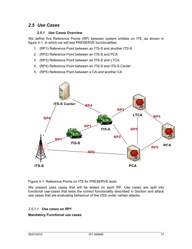
We define five Reference Points (RP) between system entities on ITS, as shown in figure 4-1, in which we will test PRESERVE functionalities
1. (RP1) Reference Point between an ITS-S and another ITS-S
2. (RP2) Reference Point between an ITS-S and PCA
3. (RP3) Reference Point between an ITS-S and LTCA
4. (RP4) Reference Point between an ITS-S and ITS-S Center
5. (RP5) Reference Point between a CA and another CA
Figure 4-1: Reference Points on ITS for PRESERVE tests
We present uses cases that will be tested on each RP. Use cases are split into functional use-cases that tests the correct functionality described in Section and attack use cases that are evaluating behaviour of the VSS under certain attacks.
2.5.1.1 Use cases on RP1 Mandatory Functional use cases
ITS-S
ITS-S Center
ITS-S
ITS-S
PCA
LTCA
RCA RP1
RP1
RP2
RP2
RP3 RP4
RP4
RP5
RP5
RP5

08/01/2014 IST-269994 18
1 F-PSN-01 Pseudonym Change on request or at system startup (OBU)
2 F-PSN-03
Lock pseudonym change
3 F-SIG-01 Verification of a signed CAM in cooperative safety applications, e.g. RHS
4 F-SIG-02 Verification of a signed DENM message
5 F-SIG-03 CAM/DENM Processing at very high rate
6 F-ENC-01 Encrypted sending of Traffic Information to TCC
Mandatory attack use cases
7 A-SIG-01 Using invalid signatures in CAMs
8 A-SIG-02 Using invalid signatures in DENMs
9 A-SIG-03 Using unauthorized signatures
10 A-CER-01 Root certificate missing
11 A-CER-02 PCA certificate missing – Pseudonym certificate cannot be verified
12 A-CER-03 Using expired or otherwise invalid certificates in CAMs
13 A-SIG-04 DoS Overload Attack
14 A-SIG-05 Time adjustment / replay attacks
Optional functional use cases
1 F-SNS-01 Usage of other signed safety messages in application
2 F-SNS-02 Usage of signed message for service advertisement from a RSU, e.g. SAM
3 F-SNS-03 Usage of pseudonym certificates with compressed public keys
Optional attack use cases
4 A-CON-01 Sending correctly signed messages with invalid content
5 A-PSN-01 Attacker trying to identify pseudonym change

08/01/2014 IST-269994 19
2.5.1.2 Use cases on RP2 Mandatory functional use cases
1 F-PSN-02 Pseudonym Certificate Refill
Mandatory attack use cases
Optional functional use cases
Optional attack use cases
1 A-CER-06 Attacks on PCA
2.5.1.3 Use cases on RP3 Mandatory functional use cases
1 F-CER-01 Issuing a certificate to a new vehicle during production
2 F-CER-02 Updating of a LT certificate before it expires
3 F-CER-03 Updating of a LT certificate after it has expired
Mandatory attack use cases
Optional functional use cases
Optional attack use cases
1 A-CER-05 Attacks on LTCA
2.5.1.4 Use cases on RP4 Mandatory functional use cases
1 F-ENC-01 Encrypted sending of Traffic Information to TCC

08/01/2014 IST-269994 20
2.5.1.5 Use cases on RP5 Mandatory functional use cases
1 F-CER-04
PCA requests an authorization from LTCA for providing new pseudonyms reloading to a requesting ITS-S station
Optional attack use cases
1 A-CER-04 Attacks on RCA
2.5.1.6 Internal ITS-S use cases Mandatory functional use cases
Optional functional use cases
1 F-IVS-01 Protected access to In-vehicle sensor
2 F-CON-01 Detection of inconsistent data
Optional attack use cases
3 A-IVS-01 Attaching tampered sensors
2.5.2 Use Cases Details
2.5.2.1 Use Case Template Each use case is detailed in a separate table, following the template below.
Use Case Name: Name of use case
Use Case Code: Code of use case (F=Functional; A=Attack)
Use Case Type: Mandatory/Optional, Functional/Attack
Prerequisites: Prerequisites for testing use case
Actions: Actions performed during use case
Expected Result: Expected result of actions

08/01/2014 IST-269994 21
Relevant for which trial:
IFT1, IFT2, EJFT, JFT
Measured values: Values measured during use case, and the frequency of reading (see Figure 2-1)
2.5.2.2 Use cases on RP1 Mandatory functional use cases
Use Case Name: Pseudonym Change on request or at system startup (OBU)
Use Case Code: F-PSN-01
Use Case Type: Mandatory Functional
Prerequisites: VSS has non revoked/expired LT certificate
VSS has at least two non-expired pseudonym certificates
VSS receives a pseudonym change request or triggers a pseudonym change by itself.
Actions: VSS checks that no pseudonym change lock is set. If at least one application has set a lock using the function lockPseudonymChange()!then!VSS!has!to!wait!until!unlockPseudonymChange()!is!called!by!the!same!application!or!until!the!requested!duration!is!expired.!VSS blocks message generation on all message generating layers (i.e. Facilities Layer)
VSS triggers flushing of messages on all layers (i.e. Facilities Layer, Network Layer, MAC Layer)
VSS requests MAC address, Node ID and Station ID change to the MAC Layer, Network Layer (e.g. GeoNet layer) and Facilities Layer by providing the 8 bytes of the pseudonym certificate CertId8.
VSS receives an acknowledgement about MAC address, Node ID and Station ID change from different layer
VSS deblocks outgoing message processing at message generating layers (i.e. Facilities Layer)
VSS uses the new pseudonym certificate to sign outgoing messages and verify incoming messages
Expected Result: VSS has a new pseudonym
Relevant for which trial:
JFT

08/01/2014 IST-269994 22
Measured values: Time between pseudonym change request and finish of process
Use Case Name: Lock Pseudonym Change
Use Case Code: F-PSN-03
Use Case Type: Mandatory Functional
Prerequisites: VSS has non revoked/expired LT certificate
VSS has at least two non-expired pseudonym certificates
VSS receives a pseudonym freeze request
VSS receives a pseudonym change request or triggers a pseudonym change by itself.
An application sends a request to lock pseudonym change for a specified period of time
Actions: The Pseudonym Management Module (PMM) of the VSS receives the request, checks that the application is authorized (PRECIOSA module). Any future or current pseudonym change process is blocked.
Expected Result: VSS blocks the pseudonym change for the specified time and then authorizes the change.
Relevant for which trial:
JFT, IFT2
Measured values: Delay between call and actual lock. Delay between lock and release (should be in line with the specified period).
Use Case Name: Verification of signed CAM messages
Use Case Code: F-SIG-01
Use Case Type: Mandatory Functional
Prerequisites: LT certificate, pseudonym certificate valid
HSM initialized (EZ-USB firmware, FPGA bitstream and Linux image)
VSS receives a CAM to be signed
08/01/2014 IST-269994 23
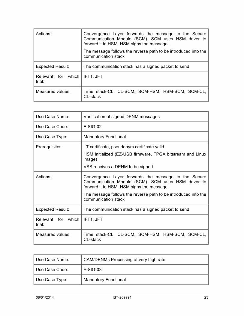
Actions: Convergence Layer forwards the message to the Secure Communication Module (SCM). SCM uses HSM driver to forward it to HSM. HSM signs the message.
The message follows the reverse path to be introduced into the communication stack
Expected Result: The communication stack has a signed packet to send
Relevant for which trial:
IFT1, JFT
Measured values: Time stack-CL, CL-SCM, SCM-HSM, HSM-SCM, SCM-CL, CL-stack
Use Case Name: Verification of signed DENM messages
Use Case Code: F-SIG-02
Use Case Type: Mandatory Functional
Prerequisites: LT certificate, pseudonym certificate valid
HSM initialized (EZ-USB firmware, FPGA bitstream and Linux image)
VSS receives a DENM to be signed
Actions: Convergence Layer forwards the message to the Secure Communication Module (SCM). SCM uses HSM driver to forward it to HSM. HSM signs the message.
The message follows the reverse path to be introduced into the communication stack
Expected Result: The communication stack has a signed packet to send
Relevant for which trial:
IFT1, JFT
Measured values: Time stack-CL, CL-SCM, SCM-HSM, HSM-SCM, SCM-CL, CL-stack
Use Case Name: CAM/DENMs Processing at very high rate
Use Case Code: F-SIG-03
Use Case Type: Mandatory Functional

08/01/2014 IST-269994 24
Prerequisites: Application/scenario that generate CAM/DENM at high rate
Actions: Convergence Layer forwards the message to the Secure Communication Module (SCM). SCM uses HSM driver to forward it to HSM. HSM signs/verify the message.
The message follows the reverse path to be introduced into the communication stack
Expected Result: The communication stack has a signed (resp. verified) packet to send (resp. forward)
Relevant for which trial:
IFT1, JFT
Measured values: Time stack-CL, CL-SCM, SCM-HSM, HSM internal, HSM-SCM, SCM-CL, CL-stack, number of messages received by second
Mandatory attack use cases
Use Case Name: Using invalid signatures in CAMs
Use Case Code: A-SIG-01
Use Case Type: Mandatory Attack
Prerequisites:
Actions: Attacker signs CAM with invalid signature, i.e. signature algorithm different (RSA instead of ECDSA), key size diferrent (e.g. ECDSA 224), signature size different to what is expected or signature missing (size 0).
Expected Result: Receiver cannot verify the signed CAM
Receiver VSS adds marker “unverifiable signature” in metadata before forwarding it to application layer
Relevant for which trial:
Measured values: Time lost in signature verification
Time spent by the attacker to generate invalid signature
Use Case Name: Using invalid signatures in DENMs

08/01/2014 IST-269994 25
Use Case Code: A-SIG-02
Use Case Type: Mandatory Attack
Prerequisites:
Actions: Attacker signs DENM with invalid signature, i.e. signature algorithm different (RSA instead of ECDSA), signature size different to what is expected.
Expected Result: Receiver cannot verify the signed DENM
Receiver VSS adds marker “unverifiable signature” in metadata before forwarding it to application layer
Relevant for which trial:
Measured values: Time lost in signature verification
Time spent by the attacker to generate invalid signature
Use Case Name: Using unauthorized signatures
Use Case Code: A-SIG-03
Use Case Type: Mandatory Attack
Prerequisites:
Actions: Attacker uses a signature with no certificate (or expired, or valid later)
Receiver verifies the certificate and message failed the test
Expected Result: Receiver VSS adds marker “unverifiable certificate” in metadata before forwarding it to application layer
Relevant for which trial:
Measured values: Time lost for certificate verification (number of verification per second)
Use Case Name: Root certificate missing
Use Case Code: A-CER-01

08/01/2014 IST-269994 26
Use Case Type: Mandatory Attack
Prerequisites: VSS has invalid, expired or revoked root certificate
Actions: Stop operation of VSS and trigger new initialization of VSS (F-CER-01)
Expected Result: Signing and verifying of messages is not possible
Relevant for which trial:
Measured values:
Use Case Name: PCA certificate missing – Pseudonym certificate cannot be verified
Use Case Code: A-CER-02
Use Case Type: Mandatory Attack
Prerequisites: VSS has invalid, expired or revoked PCA certificate
VSS cannot verify incoming message sender certificate as the issuer (PCA) is not known
Actions: Download the PCA certificate from the own “home” PCA.
Request the PCA certificate from the neighbouring ITS station whose pseudonym certificate is not verifiable.
Download the CRL from the RCA.
Check that PCA certificate is not revoked and verify the PCA certificate signature with the public key of the root certificate.
Expected Result: Pseudonym certificate can be verified.
PCA certificate is stored in Identification & Trust Management Module (IDM) of VSS and the public key is imported into the HSM.
Relevant for which trial:
IFT2, EJFT
Measured values: Time between detection of unverifiable PC and successful verification of PC.
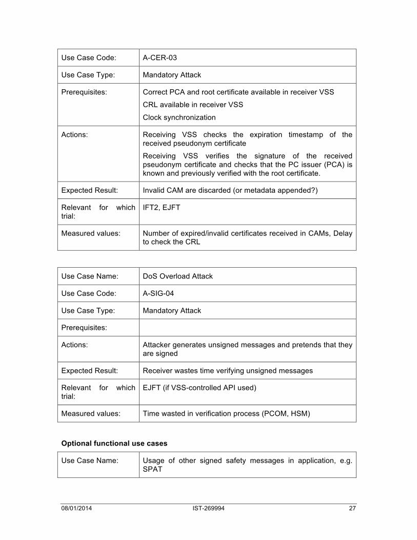
Use Case Name: Using expired or otherwise invalid certificates in CAMs
08/01/2014 IST-269994 27
Use Case Code: A-CER-03
Use Case Type: Mandatory Attack
Prerequisites: Correct PCA and root certificate available in receiver VSS
CRL available in receiver VSS
Clock synchronization
Actions: Receiving VSS checks the expiration timestamp of the received pseudonym certificate
Receiving VSS verifies the signature of the received pseudonym certificate and checks that the PC issuer (PCA) is known and previously verified with the root certificate.
Expected Result: Invalid CAM are discarded (or metadata appended?)
Relevant for which trial:
IFT2, EJFT
Measured values: Number of expired/invalid certificates received in CAMs, Delay to check the CRL
Use Case Name: DoS Overload Attack
Use Case Code: A-SIG-04
Use Case Type: Mandatory Attack
Prerequisites:
Actions: Attacker generates unsigned messages and pretends that they are signed
Expected Result: Receiver wastes time verifying unsigned messages
Relevant for which trial:
EJFT (if VSS-controlled API used)
Measured values: Time wasted in verification process (PCOM, HSM)
Optional functional use cases
Use Case Name: Usage of other signed safety messages in application, e.g. SPAT
08/01/2014 IST-269994 28
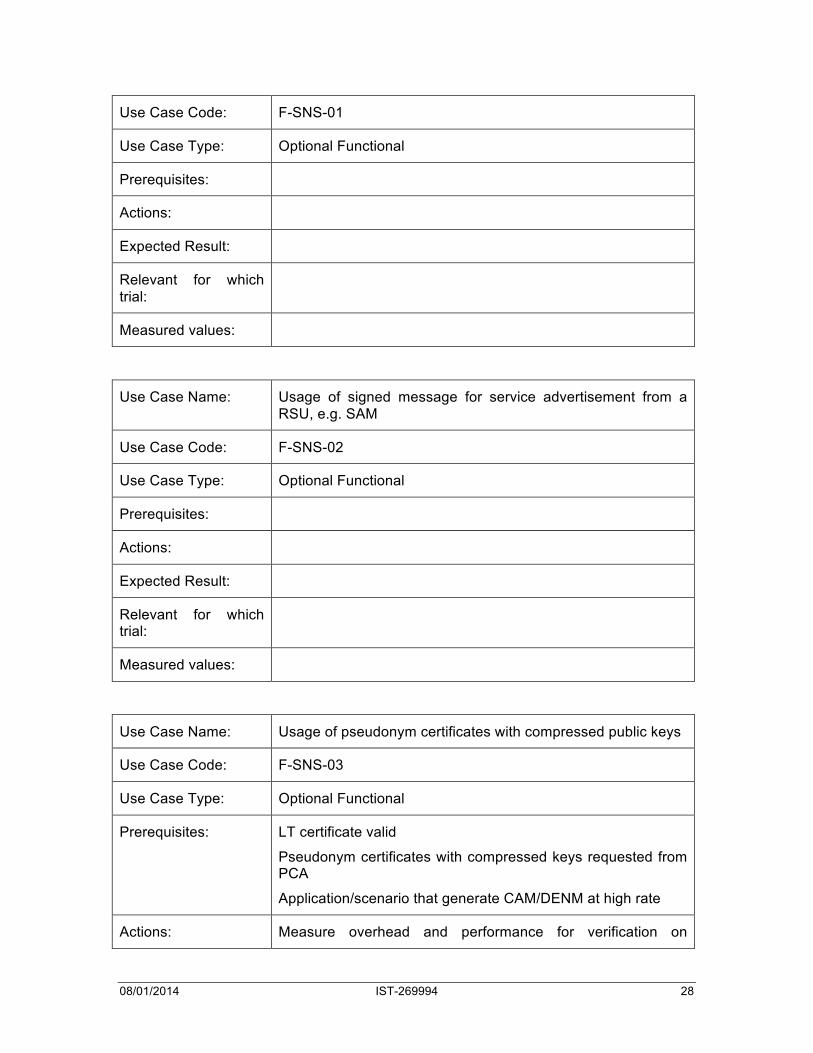
Use Case Code: F-SNS-01
Use Case Type: Optional Functional
Prerequisites:
Actions:
Expected Result:
Relevant for which trial:
Measured values:
Use Case Name: Usage of signed message for service advertisement from a RSU, e.g. SAM
Use Case Code: F-SNS-02
Use Case Type: Optional Functional
Prerequisites:
Actions:
Expected Result:
Relevant for which trial:
Measured values:
Use Case Name: Usage of pseudonym certificates with compressed public keys
Use Case Code: F-SNS-03
Use Case Type: Optional Functional
Prerequisites: LT certificate valid
Pseudonym certificates with compressed keys requested from PCA
Application/scenario that generate CAM/DENM at high rate
Actions: Measure overhead and performance for verification on
08/01/2014 IST-269994 29
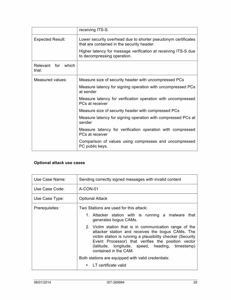
receiving ITS-S.
Expected Result: Lower security overhead due to shorter pseudonym certificates that are contained in the security header.
Higher latency for message verification at receiving ITS-S due to decompressing operation.
Relevant for which trial:
Measured values: Measure size of security header with uncompressed PCs
Measure latency for signing operation with uncompressed PCs at sender
Measure latency for verification operation with uncompressed PCs at receiver
Measure size of security header with compressed PCs
Measure latency for signing operation with compressed PCs at sender
Measure latency for verification operation with compressed PCs at receiver
Comparison of values using compresses and uncompressed PC public keys.
Optional attack use cases
Use Case Name: Sending correctly signed messages with invalid content
Use Case Code: A-CON-01
Use Case Type: Optional Attack
Prerequisites: Two Stations are used for this attack:
1. Attacker station with is running a malware that generates bogus CAMs.
2. Victim station that is in communication range of the attacker station and receives the bogus CAMs. The victim station is running a plausibility checker (Security Event Processor) that verifies the position vector (latitude, longitude, speed, heading, timestamp) contained in the CAM.
Both stations are equipped with valid credentials:
• LT certificate valid
08/01/2014 IST-269994 30
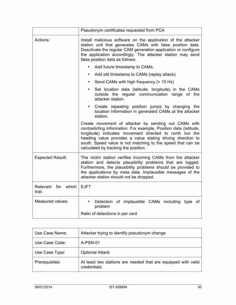
Pseudonym certificates requested from PCA
Actions: Install malicious software on the application of the attacker station unit that generates CAMs with false position data. Deactivate the regular CAM generation application or configure the application accordingly. The attacker station may send false position data as follows:
• Add future timestamp to CAMs.
• Add old timestamp to CAMs (replay attack).
• Send CAMs with high frequency (> 10 Hz)
• Set location data (latitude, longitude) in the CAMs outside the regular communication range of the attacker station.
• Create repeating position jumps by changing the location information in generated CAMs at the attacker station.
Create movement of attacker by sending out CAMs with contradicting information. For example, Position data (latitude, longitude) indicates movement directed to north but the heading value provides a value stating driving direction to south. Speed value is not matching to the speed that can be calculated by tracking the position.
Expected Result: The victim station verifies incoming CAMs from the attacker station and detects plausibility problems that are logged. Furthermore, the plausibility problems should be provided to the applications by meta data. Implausible messages of the attacker station should not be dropped.
Relevant for which trial:
EJFT
Measured values: • Detection of implausible CAMs including type of problem
Ratio of detections in per cent
Use Case Name: Attacker trying to identify pseudonym change
Use Case Code: A-PSN-01
Use Case Type: Optional Attack
Prerequisites: At least two stations are needed that are equipped with valid credentials:

08/01/2014 IST-269994 31
• LT certificate valid
Pseudonym certificates requested from PCA
Actions: 1st station performs regularly a pseudonym change while the 2nd station is in communication range. The 2nd station eavesdrop the messages of the 1st station and try to track it.
The 2nd station is running a vehicle tracker (Security Event Processor) that verifies the position vector (latitude, longitude, speed, heading, timestamp) contained in the CAMs.
Expected Result: Attacker fails if pseudonym changing station is performing the change in specific situations and with specific measurements. The station may change the pseudonym in mix zones where several other vehicles are present and the other vehicles are changing their pseudonyms as well.
If the pseudonym changing station is not performing such measurements to hide its pseudonym change, then it is expected that the attacker is able to detect the pseudonym change as long as it is in single-hop communication range.
Relevant for which trial:
Measured values: Number of pseudonym changes when other stations are in communication range.
Number of correct identification/tracking if other stations are in communication range (should be as low as possible)
2.5.2.3 Use cases on RP2
Mandatory functional use cases
Use Case Name: Pseudonym Certificate Refill
Use Case Code: F-PSN-02
Use Case Type: Mandatory Functional
Prerequisites: VSS has root certificate, LTCA certificate and PCA certificate.
VSS has updated the CRL and has checked that stored CA certificates are not revoked.
VSS has non-revoked/expired LT certificate.
Connection to pseudonym provider (i.e. PCA).
Actions: The Pseudonym Management Module (PMM) of the VSS requests the generation of one or several new ECC-224 key
08/01/2014 IST-269994 32
pairs from the HSM. The public keys are used to generate a pseudonym certificate request that is signed by the long-term private key and is encapsulated in a UPD packet. This UDP packet is sent to the PCA.
The PCA checks the validity of the signature in collaboration with the LTCA.
The PCA provides a certificate response that contains the PCs that should be stored inside the PMM together with the HSM key handles. The received PCs should be verified with the PCA certificate before they are stored.
Expected Result: VSS refilled with pseudonym certificate
Relevant for which trial:
Measured values: Delay between call and storage of pseudonym certificates.
Delay of key generation, request signing and request encryption at the VSS. These three steps can be done in a preparation process before a communication link exists to the PCA.
Delay for PC verification.
Optional attack use cases
Use Case Name: Attacks on PCA
Use Case Code: A-CER-06
Use Case Type: Optional Attack
Prerequisites: PCA installed and running
PCA not expired and not revoked
Actions: Send correct pseudonym certificate request signed with unknown LTC
Send duplicate pseudonym certificate request with the same LTC as signer and overlapping validity. PCA / LTCA should allow only limited pseudonyms valid for the same time interval.
Send correct pseudonym certificate request with not allowed permissions, expiration and validity time, geographical validity
Send malformed pseudonym certificate request
Send malformed CRL request
Send malformed certificate retrieval request
08/01/2014 IST-269994 33
DoS overload Attack
Expected Result: Receive error message from PCA in case of invalid or malformed request
Relevant for which trial:
Measured values: DoS resistance of PCA
- Number of unencrypted messages processed per second
- Number of correctly encrypted messages processed per second
- Number of CRL downloads per second - Number of certificate retrieval requests per second
with varying number of database entries
2.5.2.4 Use cases on RP3 Mandatory functional use cases
Use Case Name: Issuing a certificate to a new vehicle during initial setup
Use Case Code: F-CER-01
Use Case Type: Mandatory Functional
Prerequisites: VSS has root certificate, LTCA certificate and PCA certificate.
VSS has updated the CRL and has checked that stored CA certificates are not revoked.
Connection to LTCA
HSM is registered with a globally unique canonical identifier and the uncompressed public ECDSA key at the LTCA. The ID should consist of 16 bytes with the first 3 bytes identifying the manufacturer and the remaining 13 bytes assigned by the manufacturer, e.g., as an increasing number. The public key consists of an X and Y part.
Actions: The Identification & Trust Management Module (IDM) of the VSS requests the generation of a new ECC-256 key pair from the HSM. The public key is used to generate a long-term certificate request that is signed by the IDK private key and is encapsulated in a UPD packet. This UDP packet is sent to the LTCA. The LTCA then provides a certificate response that contains the LTC that should be stored inside the IDM together

08/01/2014 IST-269994 34
with the HSM key handles. The received LTC should be verified with the LTCA certificate before it is stored.
The Pseudonym Management Module (PMM) of the VSS requests the generation of one or several new ECC-224 key pairs from the HSM. The public keys are used to generate a pseudonym certificate request that is signed by the long-term private key and is encapsulated in a UPD packet. This UDP packet is sent to the PCA. The PCA then provides a certificate response that contains the PCs that should be stored inside the PMM together with the HSM key handles. The received PCs should be verified with the PCA certificate before they are stored.
Expected Result: The vehicle is registered at the PKI, has a valid long-term certificate and valid short-term pseudonym certificates
Relevant for which trial:
IFT1, JFT
Measured values: Delay between call and storage of certificate
Delay of key generation, request signing and request encryption at the VSS. These three steps can be done in a preparation process before a communication link exists to the PKI.
Delay for certificate verification.
Use Case Name: Updating of a LT certificate before it expires
Use Case Code: F-CER-02
Use Case Type: Mandatory Functional
Prerequisites: VSS has root certificate and LTCA certificate.
VSS has updated the CRL and has checked that stored CA certificates are not revoked.
The IDM of the VSS checks frequently (order of magnitude to be defined) the validity of LT certificate.
Actions: The VSS contacts the PKI (using G5 or 3G) and requests a new LT certificate. The Identification & Trust Management Module (IDM) of the VSS requests the generation of a new ECC-256 key pair from the HSM. The public key is used to generate a long-term certificate request that is signed by the IDK private key (or by the private key of the still valid LTC) and is encapsulated in a UPD packet. This UDP packet is sent to the LTCA. The LTCA then provides a certificate response that

08/01/2014 IST-269994 35
contains the new LTC that should be stored inside the IDM together with the HSM key handles.
Expected Result: VSS (i.e. Identification & Trust Management Module) has a new LT certificate.
Relevant for which trial:
IFT1
Measured values Time between detection of soon expired LT certificate and reception of new LT certificate
Use Case Name: Updating of a LT certificate after it has expired
Use Case Code: F-CER-03
Use Case Type: Mandatory Functional
Prerequisites: VSS has RCA certificate and LTCA certificate.
VSS updated the CRL and has checked that stored CA certificates are not revoked.
Actions: See updating of a LT certificate before it expires, only the IDK private key can be used for signing the request.
Expected Result: VSS (i.e. Identification & Trust Management Module) has a new LT certificate
Relevant for which trial:
IFT1
Measured values:
Optional attack use cases
Use Case Name: Attacks on LTCA
Use Case Code: A-CER-05
Use Case Type: Optional Attack
Prerequisites: LTCA installed and running
LTCA not expired and not revoked
Actions: Send malformed VSS registration request to LTCA (wrong or duplicate ID, wrong or malformed IDK public key)

08/01/2014 IST-269994 36
Send correct long-term certificate request signed with unknown IDK key
Send duplicate long-term certificate request with the same IDK as signer
Send correct long-term certificate request with not allowed permissions, expiration and validity time, geographical validity
Send malformed long-term certificate request
Send malformed CRL request
Send malformed certificate retrieval request
DoS overload Attack
Expected Result: Receive error message from LTCA in case of invalid or malformed request
Relevant for which trial:
Measured values: DoS resistance of LTCA
- Number of unencrypted messages processed per second
- Number of correctly encrypted messages processed per second
- Number of CRL downloads per second - Number of certificate retrieval requests per second
with varying number of database entries
2.5.2.5 Use cases on RP4
Use Case Name: Encrypted sending of Traffic Information to TCC
Use Case Code: F-ENC-01
Use Case Type: Optional Functional
Prerequisites: VSS has an encryption key
HSM initialized (EZ-USB firmware, FPGA bitstream and Linux image)
Actions: A vehicle sends encrypted message to the TCC. The TCC decrypts the message
Expected Result: Successful decryption
Relevant for which
08/01/2014 IST-269994 37
trial:
Measured values: Delay for encryption, decryption, transfer delay
2.5.2.6 Use cases on RP5 Mandatory functional use cases
Use Case Name: PCA requests authorization from LTCA to refill pseudonyms
Use Case Code: F-CER-04
Use Case Type: Mandatory Functional
Prerequisites: PCA and LTCA is equipped with valid certificate
PCA has connection information about LTCA (i.e. IP addresses and port numbers)
PCA and LTCA certificate have non-zero values in the permissions field.
Actions: PCA verifies that the permissions of the requested PCs are matching its own permissions and regional restrictions contained in the PCA certificate.
PCA create connection to LTCA
PCA verifies that the permissions of the requested PCs are matching the permissions and regional restrictions contained in the LTCA certificate.
PCA creates authorization and validation request and sends it to the LTCA.
LTCA verifies that the permissions of the authorization request are matching the permissions and regional restrictions contained in the PCA certificate.
LTCA verifies that the permissions of the authorization request are matching its own permissions and regional restrictions contained in the LTCA certificate.
LTCA verifies that issuance policy is considered. Only a restricted number of PCs shall be issued valid for the same time interval and region. Also the expiration time of requested PCs shall be limited.
If an error occurs during permission and policy verification, the LTCA provides an error to the PCA that is forwarded by the PCA to the requesting ITS-S.
If verifications at the LTCA are successful, the LTCA provides permissions, region information and expiration information to the PCA which is then allowed to generate the PCs.

08/01/2014 IST-269994 38
Expected Result: Time periods for which the PCA may issue PCs.
Relevant for which trial:
IFT1, JFT
Measured values: Measure at PCA time between AuthorizationValidationRequest generation and reception of AuthorizationValidationResponse.
Measure at LTCA time between AuthorizationValidationRequest reception and sending of AuthorizationValidationResponse.
Optional attack use cases
Use Case Name: Attacks on RCA
Use Case Code: A-CER-04
Use Case Type: Optional Attack
Prerequisites: RCA installed and running
Actions: Send correct CA certificate request (LTCA, PCA)
Send malformed CA certificate request
Send malformed CRL request
Send malformed certificate retrieval request
DoS overload Attack
Expected Result: Receive error message from RCA that automatic issuance of certificates not possible
Relevant for which trial:
Measured values: DoS resistance of RCA
- Number of unencrypted messages processed per second
- Number of correctly encrypted messages processed per second
- Number of CRL downloads per second - Number of certificate retrieval requests per second
with varying number of database entries

08/01/2014 IST-269994 39
2.5.2.7 Internal ITS-S Use cases This version of document does not cover internal ITS-S test use cases which are tested on EVITA project.
2.6 Research Questions & Hypothesis The PRESERVE FOT activities are conducted to investigate the following research questions. For each research questions we describe hypothesis.
• Is the VSS correctly performing the described functions in normal operation? o Hypothesis 1: The VSS is working according to the specifications in
normal operation (no attack) o Hypothesis 2: The VSS is working without fault in normal operation
• Is the VSS correctly performing the described functions under selected attack scenarios?
o Hypothesis 1: The VSS is working according to the specifications under selected attack scenarios
o Hypothesis 2: The VSS is resilient to selected attack scenarios • Is the VSS scalable to medium (30 cars) and high load scenarios (above 60 cars
with increased message rates)? o Hypothesis 1: The VSS is scalable to medium load scenarios o Hypothesis 2: The VSS is scalable to high load scenarios
• Is the VSS fulfilling the performance requirements set in PRESERVE technical report 1?
• Will pseudonym management and pseudonym change negatively affect VSS performance, e.g., by adding unacceptable delay?
o Hypothesis 1: Pseudonym change will generate unverifiable packets o Hypothesis 2: Pseudonym change will increase storage and V2I
communication o Hypothesis 3: Pseudonym management will add delay
• What is the performance difference between a software-, FPGA- and ASIC-version?
2.7 Performance Indicators & Study design In PRESERVE, we will measure and evaluate the following performance indicators:
• General message rates of incoming and outgoing packets • Maximum rates for signature generation/verification and encryption/decryption • Precise delay measurements of functions and sub-functions for signature
generation/verification and encryption/decryption • Jitter measurements of functions and sub-functions for signature
generation/verification and encryption/decryption • Rates, delays, and jitter of other functions (esp. certificate and pseudonym
management and pseudonym change) • Ratio valid vs. invalid packets during attacks (detected via signatures and data
consistency)

08/01/2014 IST-269994 40
We are going to use the same metrics as already described in the PRESERVE TR1 - V2X Security Performance Requirements:
• Certificate Cache Lookup Effectiveness CLE (0 ≤ CLE ≤ 1): The effectiveness of the certificate lookup, determined by the cache size.
• Outgoing Packets per Second OPPS (1/s): Here we measure the number of packets per second that are sent by an ITS station and that need to be processed by the VSS.
• Packet Signature Generations per Second SGPS (1/s): For every packet send, one needs to generate a suitable signature, i.e. SGPS = OPSS. Note that we assume that every packet needs to be signed, which is true at least for CAMs and DENMs, if we don’t apply omission schemes.
• Incoming Packets per Second IPPS (1/s): Here we consider the number of packets per second that are received by an ITS station and that need to be processed by the VSS.
• Packet Signature Verifications per Seconds SVPS (1/s): For every signed packet received, one needs to verify the signature plus (potentially) the certificate. Assuming that a certain fraction of packets contain yet unverified certificates, we get: SVPS = (1 + CLE) IPSS, 0 <= CLE <= 1
• Transmission Delay TD (ms): The "airtime" of a packet measured in ms. • Outgoing Communication Delay OCD (ms): The time that the stack needs to
transmit a packet. Note again that because of the reasons given above, this can only be a statistical value.
• Signature Generation Delay SGD (ms): The delay for generating one packet signature. This includes calculating a hash (HD) plus performing the actual digital signature generation operation. SGD = HD + SD HD = Hash Delay, SD = Signing Delay Both values include all internal delays of the VSS, e.g., the times to load keys and the time to transfer messages or other data into the HSM or out of it.
• Outgoing Packet Delay OPD (ms): To satisfy overall delay requirements (which are application specific), an outgoing packet should be sent by an ITS station within a bounded delay measured from the time the application submits the data to a SAP to the time the last bit of a packet is sent out. As we are not assuming a real-time system to be in place and as network access is only probabilistic, this can only be a statistical measure providing a certain confidence interval. For security, we consider the delay only for packets that need to be processed by the VSS, e.g., in order to attach security payload. We get: OPD = OCD + SGD
• Incoming Communication Delay ICD (ms): The delay needed by the communication stack (without security processing) to deliver a message to the application or facilities SAP where it is ready for processing.
• Signature Verification Delay SVD (ms): The delay for verifying one packet signature. This includes calculating a hash (HD) plus performing the actual digital signature verification operation. Furthermore, for a certain fraction CLE of packets, one needs to verify the certificate which is assumed to take the same amount of time as verifying the signature itself. Therefore, we get SVD = (1 + CLE)(HD + VD) + (1 - CLE) CLD
08/01/2014 IST-269994 41
HD = Hash Delay, VD = Verification Delay, CLD = Certificate Cache Lookup Delay
• Incoming Packet Delay IPD (ms): To satisfy overall delay requirements (which are application specific), an incoming packet should be available to an ITS application within a bounded delay measured from the time the last bit of the packet is received from the radio link to the time the packet is accessible to the application. For security, we consider the delay only for packets that need to be processed by the VSS, e.g., in order to verify security payload. We get: IPD = ICD + SVD
• Packet Delay PD (ms): The overall delay of a packet sent from an application or facility until it is received by a corresponding application or facility in a receiving vehicle measured from SAP to SAP. We get: PD = OPD + TD + IPD
• Pseudonym Change Delay PCD (ms): The additional delay introduced when the ITS station switches from one pseudonym to another. Measured as additional time added to a packet stream sent at maximum rate.
Each Performance Indicators (PI) will be analyzed according to a Frequency of Event, Significance. In PRESERVE each FOT is conducted in a controlled situation (in opposition to naturalistic or semi-controlled). Therefore, the Frequency of Event is known in advance and the Significance is high. Also, the FOT duration is short (order of days).
2.8 Measures & Sensors Figure 2-1 shows the points within the PRESERVE V2X Security Architecture where measurements need to be taken. Position 1 is in the Convergence Layer where usage rates and statistics about the general use of the VSS can be kept. Depending on the API in use, this will include different parameters. Position 2 is only relevant in case of the VSS-managed API. In this case, position 1 will only be able to measure rates at which packets are passed to the VSS. Details about how these messages are then processed can only be collected at position 2. Position 3 will allow recording pseudonym change rates and timing while position 4 allows recording measurements related to identity management, e.g., certificate updates. Position 5 will allow to measure the exact cryptographic load that is put on the OBU and the HSM (depending on the functional split between HSM and OBU) as all cryptographic operations are passed through the cryptographic services. Finally, position 6 will allow to measure internal parameters of the HSM.

08/01/2014 IST-269994 42
Convergence)Layer
In.Vehicle
V2X)Comm.)Stack
MAC)Layer
Network)Layer
Facilities)Layer
Application)Layer
Transport)Layer
PRESERVE)V2X)Security)Architecture
Secure)Communication)
Module
Pseudonym)Manag.)Module
Entity)Auth.)Mod.
Platform)Int.)Mod.
Policy)Decision)Mod.
Open)SSL
Sensors
ECUs
Head)Unit
SensorsSensors
HSMCrypto.)Services
CAN)Bus
Comm.)Control)Module
Inter)Layer)Proxy
CL)Internal)API
CL)External)A
PI ID)&)Trust)Management)
Module
TPM
LegendX Y X)use)service)of)Y
SevecomMod.
EVITA)Module
External)SW/HW
PRECIOSA)Mod.
Optional)comp.
Security)Event)Processor
Management)and)Configuration
Priv.)Enf.)Runtime)
Architecture
PeRAImporterExporterQuery)API
Comm.)Layer Sec.)Services
Security)Supp. HW)Layer
1
2
56
3
4
Figure 2-1: Points of Measurement
Measurement point 1 (Convergence Layer):
• OPPS • IPPS
Measurement point 2 (Secure Communication Module):
• SGD • SVD
Measurement point 3 (Pseudonym Management Module):
• PCD (pseudonym change delay) • Pseudonym change success rate
Measurement point 4 (ID&Trust Management Module):

08/01/2014 IST-269994 43
• CLE
Measurement point 5 (Cryptographic Services):
• SGPS • SVPS • HD • SD
Measurement point 6 (HSM) TBC
External Measurements:
• TD • OCD
The main goal of PRESERVE tests is to measure the delays introduced by PRESERVE VSS system. This measurement of considered delays in our approach are using the Performance Indicators defined in section 7. Additional tests will allow to perform security and dependability analysis of the Security FOTs.
The test methodology developed for security performance analysis of FOTs is based on the following approach:
1. Cryptographic overhead analysis: these tests will evaluate the performance of the crypto-system, e.g. cryptographic delays for signature generation/verification operations,
2. Protocol stack analysis: test and evaluation of delays/overhead relating to the Preserve VSS internal processing, outside of the Geonetworking stack operation,
3. Measurement of Application to Application delays: this can be performed cooperative applications developed by FOTs such as Score@F or DriveC2X. Currently the PRESERVE VSS is integrated into Score@F OBUs which provide available FOT applications running the ITS communication stack. This includes more than 8 different applications demonstrating the signalling of road hazards (based on ETSI TS 101 539-1 standard) and the generation/reception of road traffic information (e.g. Variable Message signalling, contextual speed limit).
A PING PONG application can also be used for these measurements. It enables to emulate various application environment such as:
• Generate different packet sizes
• Generate various arrival rates of packets
• Inject attacker behaviour (e.g. wrong signature)
This test application is running a configuration of ping code (similar to iputils) which uses the Geonet protocol implemented on the ITS station.
The following table 8-2 gives the detailed description of test scenarios and logging facilities used to support performance testing in internal or external FOT.

08/01/2014 IST-269994 44
Inter
nal1
Exter
nal2
Performance
Indicator
Description Comment
X" Rate General) message) rates) of) incoming) and)
outgoing)packets Set)the)rates)of)incoming)and)outgoing)packets)for)
the)PING)application.)Flooding)the)VSS)with)PING)
packets)to)test)its)efficiency.)
X" Max)Crypto)Rate Maximum) rates) for) signature)
generation/verification) and) encryption/)
decryption)
Test)operation)directly)on)the)HSM)with)testcases)
already) in) the) SVN) or) use) of) the)
LogMemoryAndTimeStats) class) to) measure) the)
latency)of)the)PCOM)interface.)
X" Crypto)delay Precise)delay)measurements)of)functions)and)
subJfunctions) for) signature)
generation/verification) and) encryption/)
decryption)
The)LogMemoryAndTimeStats)class)can)be)used)to)
evaluate)precise)delays.)
X" X Crypto)Jitter Jitter) measurements) of) functions) and) subJ
functions) for) signature) generation/)
verification)and)encryption/)decryption)
Test)VSS)behavior)with)variations)of)arrival) rates)
(e.g.) incoming) packets) following) Poisson)
distribution))or)using)the)Score@F)applications)in)
a)test)scenario.))
The)LogMemoryAndTimeStats)class)can)be)used)to)
evaluate)precise)delays)offline.)
X" X Other)Jitter Rates,) delays,) and) jitter) of) other) functions)
(esp.)certificate)and)pseudonym)management)
and)pseudonym)change))
same)as)for)crypto)jitter)
1 Internal FOT testing is done using a test bench (or could use some simulation tools) 2 External FOT testing means security testing done with a cooperative-ITS FOT like Score@F or DriveC2X

08/01/2014 IST-269994 45
X Attack)ratio) Ratio)valid)vs.) invalid)packets)during)attacks)
(detected) via) signatures) and) data)
consistency))
Need) a) framework) to) create) invalid)
signatures/packets,) so) that) they) are) used) in) the)
measurements.)Test)efficiency)for)a)broad)
range)of)valid)vs.)invalid)signatures)ratio.
X CLE) Certificate)Cache)Lookup)Effectiveness) (0)<=)
CLE)<=)1):)The)effectiveness)of)the)certificate)
lookup,)determined)by)the)cache)size.)
Investigate) if) the) PCOM) supports) this) operation)
(e.g.,) LogMemoryAndTimeStats) class)) and) plan) a)
testbed)with)vehicles.)
X OPPS) Outgoing)Packets)per)Second)(1/s):)Here)we)
measure) the) number) of) packets) per) second)
that)are)sent)by)an)ITS)station)and)that)need)
to)be)processed)by)the)VSS.)
Note)that)this)measurement)can)be)dependent)on)
the) application) so) this) metric) should) normally)
reflect) particular) applications.) Evaluations) could)
be)obtained)for)a)few)of)those.)
X IPPS) Incoming)Packets)per)Second)(1/s):)Here)we)
consider) the) number) of) packets) per) second)
that) are) received) by) an) ITS) station) and) that)
need)to)be)processed)by)the)VSS.)
This) could) be) application) dependent,) since)
different) applications) can) have) different) arrival)
rates)of)incoming)packets.)
X SVPS) Signature) Verifications) per) Seconds) (1/s):)
For)every) signed)packet) received,)one)needs)
to) verify) the) signature) plus) (potentially)) the)
certificate.)Assuming)that)a)certain)fraction)of)
packets) contain) yet) unverified) certificates,)
we)get:)SVPS)=)(1)+)CLE))IPSS,)0)<=)CLE)<=)1)
The)LogMemoryAndTimeStats)class)can)be)used)to)
evaluate) precise) delays.) (It) could) be) done) offline)
by)evaluating)CLE)and)IPPS))
X OCD) Outgoing) Communication) Delay) (ms):) The)
time) that) the) stack) needs) to) transmit) a)
packet.)Note)again)that)because)of)the)aboveJ
mentioned) reasons,) this) can) only) be) a)
statistical)value.)
OCD)can)be)measured)using) the)PING)application)
without)measuring)the)roundJtrip)time.)
X SGD) Signature) Generation) Delay) (ms):) The) delay)
for) generating) one) packet) signature.) This)
includes) calculating) a) hash) (HD)) plus)
This) functionality) should) be) present) in) the)
libpreserve) tests.) Use) of) the)
LogMemoryAndTimeStats)class)

08/01/2014 IST-269994 46
performing) the) signature) generation)
operation.)
SGD)=)HD)+)SD)
HD)=)Hash)Delay,)SD)=)Signing)Delay))
Both)values) include)all) internal)delays)of) the)
VSS,)e.g.,) the)times)to) load)keys)and)the)time)
to) transfer) messages) or) other) data) into) the)
HSM)or)out)of)it.)
X SVD) Signature)Verification)Delay) (ms):) The)delay for) verifying) one) packet) signature.) This)
includes) calculating) a) hash) (HD)) plus)
performing) the) signature) verification)
operation.)Furthermore,)for)a)certain)fraction)
CLE) of) packets,) one) needs) to) verify) the)
certificate)which)is)assumed)to)take)the)same)
amount) of) time) as) verifying) the) signature)
itself.))
Therefore,)we)get)SVD)=)(1)+)CLE)(HD)+)VD))
+)(1)J)CLE))CLD))
HD) =) Hash) Delay,) VD) =) Verification) Delay,)
CLD)=)Certificate)Cache)Lookup)Delay)
This) functionality) should) be) present) in) the)
libpreserve) tests.) Use) of) the)
LogMemoryAndTimeStats)class
X IPD) Incoming) Packet) Delay) (ms):) To) satisfy)
overall) delay) requirements) (which) are)
application) specific),) an) incoming) packet)
should) be) available) to) an) ITS) application)
within) a) bounded) delay) measured) from) the)
time) the) last) bit) of) the) packet) is) received)
from) the) radio) link) to) the) time) the)packet) is)
accessible)to)the)application.)For)security,)we)
consider)the)delay)only)for)packets)that)need)
to) be) processed) by) the) VSS,) e.g.,) in) order) to)
verify) security)payload.)We)get:) IPD)=) ICD)+)
Performance) can) only) be) evaluated) using) the) GN)
stack)and)Score@F)binaries)
08/01/2014 IST-269994 47
SVD)
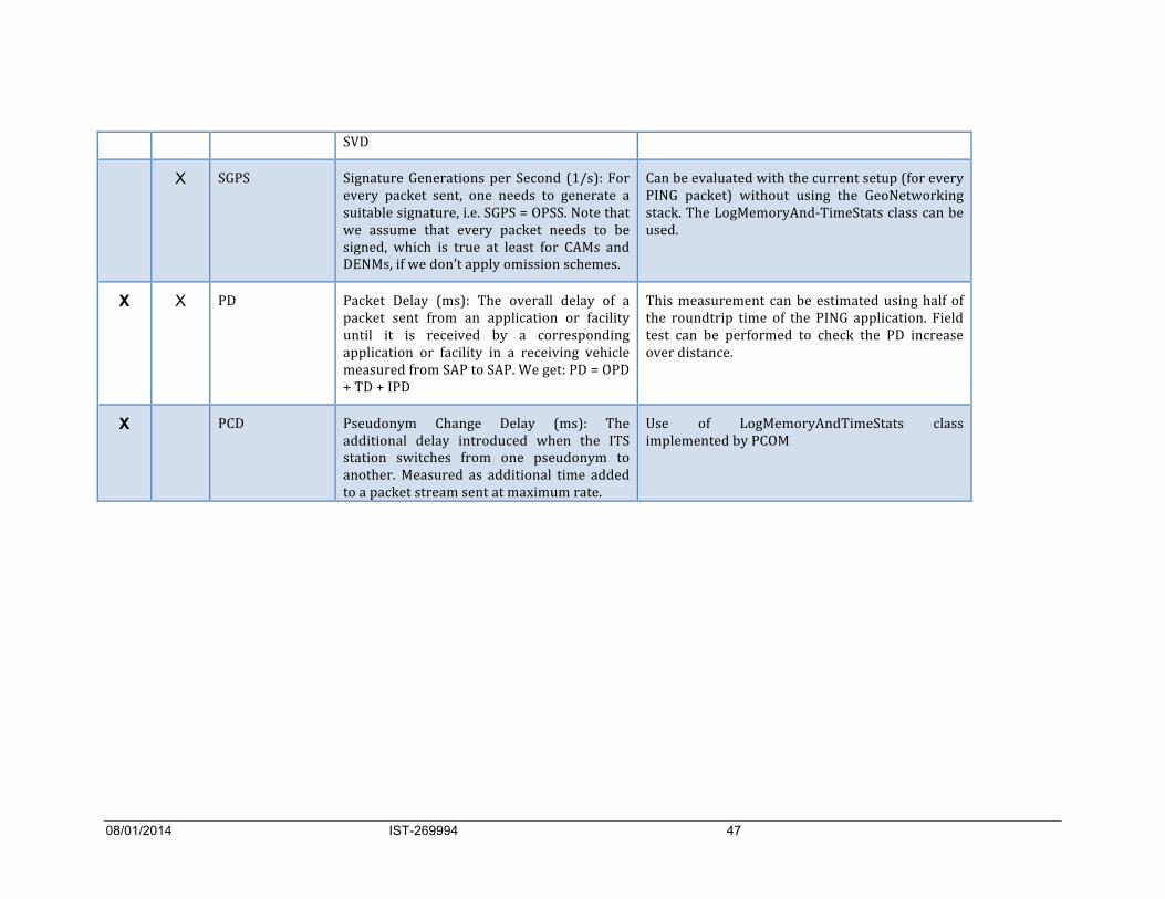
X SGPS) Signature)Generations)per)Second) (1/s):)For)
every) packet) sent,) one) needs) to) generate) a)
suitable)signature,)i.e.)SGPS)=)OPSS.)Note)that)
we) assume) that) every) packet) needs) to) be)
signed,) which) is) true) at) least) for) CAMs) and)
DENMs,)if)we)don’t)apply)omission)schemes.)
Can)be)evaluated)with)the)current)setup)(for)every)
PING) packet)) without) using) the) GeoNetworking)
stack.)The)LogMemoryAndJTimeStats)class)can)be)
used.)
X X PD) Packet) Delay) (ms):) The) overall) delay) of) a)
packet) sent) from) an) application) or) facility)
until) it) is) received) by) a) corresponding)
application) or) facility) in) a) receiving) vehicle)
measured)from)SAP)to)SAP.)We)get:)PD)=)OPD)
+)TD)+)IPD)
This)measurement) can)be)estimated)using)half)of)
the) roundtrip) time) of) the) PING) application.) Field)
test) can) be) performed) to) check) the) PD) increase)
over)distance.)
X PCD) Pseudonym) Change) Delay) (ms):) The)
additional) delay) introduced) when) the) ITS)
station) switches) from) one) pseudonym) to)
another.)Measured) as) additional) time) added)
to)a)packet)stream)sent)at)maximum)rate.)
Use) of) LogMemoryAndTimeStats) class)
implemented)by)PCOM)

08/01/2014 IST-269994 48
2.9 Data acquisition 2.9.1 Logging in the VSS
In the first version, PRESERVE will use its own solution for test data logging as explained in figure 9-1.
Figure 9-1: PRESERVE data collection principle
The data collection is done within PRESERVE VSS by the PCOM component (or the Convergence Layer). Regarding log storage (case 1), the PCOM component writes in a file inside the file system of the CCU. In case 2, the writing is done on the USB memory stick card (mounted in /media/). The writing is using basic C ANSI function open/write/read/close. More information on this topic can be found in the [6]. In this document, the user will know how to activate the logging and how the information is presented. Libpreserve)offers)a)Data)Logging)mechanism.)In)this)section)we)describe)the)different)
fields)that)can)be)found)in)the)logs.)
)
2.9.1.1 Data Logging generation!Data)logging)are)generated)if)
• libpreserve)has)been)compiled)with)the)option)_WITH_MEMORY_STAT_-• the)line)logging.with.statistics-=-1-is)present)in)the)configuration)file)
)
2.9.1.2 Data Logging description
format of an event The)Data)logging)is)a)collection)of)the)major)events)that)happen)during)the)execution)of)
libpreserve.)Each)event)is)composed)of)the)4)following)fields)separated)by)a)tab:)
NWTA VSS API
BTP
GN VSS
(DENSO WSU 015 or COHDA MK3)
CCU
Application Unit (VTC 6200)
Modem
HSM
USB memory
stick
1
2
Collecting point

08/01/2014 IST-269994 49
• the)identifier)of)the)thread)that)generated)the)event.)This)value)can)be)used)for)
identifying)which)entity)generated)the)event)in)a)multithreaded)context.)
• the)day)when)the)event)has)been)generated.)It)is)of)the)form)year/month/day-• the)time)at)which)the)event)has)been)generated.)It)is)of)the)form)
hour.minute.second.microseconds-• the)event)itself)prefixed)by)the)method)that)generated)it.)The)general)format)is)
therefore)class::method-:-event.)For)example)for)the)method)treatReceivedPDU-two)events)are)generated:)
o SecureCommunicationModule::treatReceivedPDU):)begin)when)we)enter)the)
method)
o SecureCommunicationModule::treatReceivedPDU):)end)when)we)leave)the)
method)
)
some significant events The)event)attached)to)the)pseudonym)change)is)
• PseudoManager::doPseudoChange):)"certid)of)the)new)pseudonym")
For)example)the)line)
• 3072857808)2013/06/06)14:53:28.293303)PseudoManager):):)doPseudoChange):)
671d42bdd46f4be0)
indicates)that)the)pseudonym)which)certid)is)671d42bdd46f4be0-will)be)used)for)signing.)This)event)has)been)generated)by)the)method)doPseudoChange-of)the)class)PseudoManager.))
The)event)that)indicates)that)the)creation)of)the)signature)is)successfull)is)
• CryptoModule_1609_2::Sign):)PKI)Ok)with)"certid)of)the)pseudonym)used")
For)example)the)line)
• 3072857808)2013/06/06)14:53:28.693348)CryptoModule)\)_1609)\)_2):):)Sign):)PKI)
Ok)wi)th)671d42bdd46f4be0)
indicates)that)the)pseudonym)which)certid)is)671d42bdd46f4be0-has)been)successfully)used)(PKI-Ok))for)signing)the)outgoing)message.)This)event)has)been)generated)by)the)method)Sign-of)the)class)CryptoModule_1609_2.))
The)event)that)indicates)that)the)verification)of)the)signature)is)successfull)is)
• LowLevelHSM::Verify):)PKI)Ok)
it)is)generated)by)the)method)Verify-of)the)class)LowLevelHSM.)If)the)"Verification)on)Demand")is)in)place,)PCOM)stores)an)event)each)time)the)verification)
of)the)signature)is)skipped.)For)example:)
• 3072059088)2013/06/07)12:25:24.262702)SecureCommunicationModule):):)
treatReceivedPDU))
)
Each)failure)is)indicated)by)the)corresponding)event.)Below)are)some)examples)(in)the)old)
format):)
• 22/05/2013)15:52:31.309)LowLevelHSM):):)Impor)tPlainKey):)HSM)A)l)l)Key)Space)
Occupied)
• 22/05/2013)15:52:31.309)Crypto_HSM):):)v)e)r)i)f)y):)PCOM)Load)Publ)ic)Key)Fai)led)
• 22/05/2013)15:52:31.309)CryptoModule_1609_2):):)Ve)r)i)f)y):)PCOM)Ce)r)t)i)f)i)c)a)t)e)
Chain)Validation)Failed)
before-and)after-events)have)placed)around)the)call)of)some)the)HSM)functions)in)order)

08/01/2014 IST-269994 50
to)indicate)the)time)consummed)by)these)functions.)It)is)only)for)debugging)purposes)and)
they)will)be)removed)in)a)future)version)of)the)VSS)Kit.)
In a further version, a solution for integrating PRESERVE logs will be implemented using Drive C2X test & logging framework provided by Fraunhofer FOKUS (cf. D25.1). The following steps of the FESTA methodology are to be described in a future version of this document:
• Data analysis used in Security FoT
• Impact assessment and experience gained from PRESERVE security FoT
2.9.2 Logging in the security infrastructure The PKI consists of different Certificate Authorities (CA): Root CA, Long-Term CA and Pseudonym CA. Every CA writes its log into a dedicated log file. As logging facility, log4j is used.
The logs can be accessed at the Root CA and the Long-Term CA via a web browser using the following links:
• Root CA: https://preserve-pki.sit.fraunhofer.de:8081/log
• Long-Term CA: https://preserve-pki.sit.fraunhofer.de:8082/log
In order to access the webpage of the Root CA and the Long-Term CA a user authentication is necessary by providing a valid user name and password. Figure 2-3 shows a screenshot of the logs at the Long-Term CA.
Figure 2-3: Screenshot of logs at Long-Term CA
The log entries related to certificate requests can be identified by a request identifier which is created by hashing the encoded request data. Details about the generation of the request identifier can be found in IEEE 1609.2 D9: The request identifier is the first 10 bytes of the SHA-256 hash of the CertificateRequest. The hash is calculated over the plaintext CertificateRequest before the request is encrypted.

08/01/2014 IST-269994 51
2.10 Data analysis For further data analysis, PRESERVE should use existing tools for data collecting and analysis, especially developed for FOTs of cooperative systems in Drive C2X or FOTsis.
This includes following tasks of FESTA2 methodology: • Database (Task 3200) • Data Analysis (Task 3300) • Research Questions & Hypothesis Testing (Task 3300)
2.11 Impact Assessment and Socio-economic Cost Benefit Analysis (Task 3300 and WP5)
As results of the testing become available, they will be made available to our partners in C2C-CC, ETSI, and the advisory board to discuss the impact of these results on on-going standardization, predevelopment, and deployment.
As an example, evidence on scalability of the different VSS versions (software, FPGA, ASIC) together with insight into cost structure might affect the direction of development to favour either a software solution with aggressive verification on demand or an ASIC-based HSM.
3 Score@F Test site description Score@F is the french FOT (Field-Operational Testing) for experimentation of cooperative ITS and is part of Drive C2X European project.
Score@F has set up a co-operation with PRESERVE project for performing a Security FOT on a chosen test site. This joined Security FOT is using different Score@F platforms integrating the PRESERVE VSS Kit1 version with SW or FPGA-based HSM as shown on Figure 3-1.

08/01/2014 IST-269994 52
Figure 3-1 : Score@F platforms for vehicle and road side ITS-S
This section describes Score@F test sites and especially the Satory controlled test area used for security assessment.
Score@F FOT is composed of three test sites in Yvelines-Versailles area, Isère area and Orléans area.
• Yvelines – Versailles test site Yvelines – Versailles area is the main test site for naturalistic user-experimentation, using open roads of different types (highway, urban and rural roads). See Figure 3-2: Main test site in Yvelines-Versailles.
The Yvelines – Versailles open road site includes the following elements:
• A section of RD91 / RN12 of 3.5 KM / 4.4km with 6 main spots, which leads from the RD91/ RN12 exchanger at Versailles up to the Georges Besse place in Guyancourt, entrance of Renault Technology center. This portion, located in a peri-urban / rural area has several interesting configurations.
• Urban road in Versailles city, near Versailles Chantier station, with includes 5 intersections with traffic lights.
• On highway A86, a 10 km duplex tunnel. No RSU are installed inside the tunnel.

08/01/2014 IST-269994 53
Figure 3-2: Main test site in Yvelines-Versailles
• Satory test tracks The Versailles-Satory site is used for closed road experimentation by Score@F (controlled test tracks). This site owned by Defense Ministry and managed by Nexter provides a set of 3 different tracks from 2-4 km which reproduce a large variety of road situations. The site is equipped with 6 RSUs covering the whole area (see Figure 3-3: Versailles -Satory tracks).
It is closed to IFSTTAR premise and is linked by a networking infrastructure (3G/Wimax, WiFi and G5/802.11p) between IFSTTAR building and the test tracks, therefore allowing an end-to-end connectivity between vehicles on tracks and the Test/control Centre for monitoring and collecting field-testing data.

08/01/2014 IST-269994 54
Figure 3-3: Versailles -Satory tracks
It is mainly used for system validation and for experimentation of road safety applications.
• Score@F FOT use cases Score@F is implementing and assessing use cases related to
• Road safety • Sustainable transport and traffic management • Mobility and comfort services.
The list of use cases for user open-road experimentations is described in Table 3-1: Score@F Use cases. ‘Hard’ road safety use cases will be tested on Satory test tracks (road hazard signalling and collision avoidance).

08/01/2014 IST-269994 55
Table 3-1: Score@F Use cases
Safety applications have very strong requirements on data reliability and freshness for receiving stations in the vehicular ad’hoc network (see [9]). In ETSI ITS standards, the Road Hazard Signalling (RHS) TS specifies the data quality at sender side. Especially for Class A stations a high level of accuracy, freshness and confidence is required. Additionally the end-to-end latency time for safety messages is expected to be less than 300 ms (see [12]).
Packet delay is a critical requirement for safety applications like collision avoidance (ICRW, LCRW) and for future autonomous cyber vehicle. The performances of the VSS system esp. delays due to security processing will be evaluated within PRESERVE WP3.
3.1 Joint FOT test beds description (OBU, RSU)
We conducted four test sessions with Score@F:
• July 2012 (Static tests),
• November 2012 (Satory track),
• May 2013 (CG 78 from Technocentre to Satory)
• September 2013 (Technocentre).
During the two first sessions, we integrated VSS PRESERVE on the Score@F batch 1 platform.
This platform, as presented on Figure 3-4: Score@F batch 1 platformFigure 3-4, is composed of two units: a communication unit with G5 modem/antenna and an application unit regrouping applications and facilities layers.

08/01/2014 IST-269994 56
This application unit is a Nexcom VTC6201. The application unit communicates via Ethernet to the IEEE 802.11p modem which is a DENSO or COHDA modem. An implementation of the GeoNetworking and BTP protocols (network stack) is integrated on the modem.
We integrated the VSS PRESERVE on the Score@F network stack developed by HITACHI.
On July 2012, we integrated the VSS software kit version 1.1.1 on Denso and Cohda modems.
The main objective of November 2012 test session was the test and validation of the FPGA developed by PRESERVE. For this purpose, we connected the FPGA to the modem via USB and we tested FPGA functionalities. During this session, we integrated also a new version of VSS software (version 1.2.2), that supported FPGA functionalities, on vehicle and roadside station. Moreover, we tested signed communications between roadside station (a sender Cohda modem) and a vehicle (a receiver Denso modem) on Satory track. Both are equipped with the VSS software only version 1.2.2.
Figure 3-4: Score@F batch 1 platform
PRESERVE started on 2013 the integration of the VSS on the Score@F batch 2 platform which is presented on Figure 3-5. Batch 2 platforms in Score@F have been used for the user experimentation (installed as after-sales unit in users’ own vehicles). This second platform is formed by only one unit (Nexcom VTC unit) which integrates an ITRI G5 modem as a daughter board. On May 2013, we integrated and tested VSS software version 1.4.1 on the Score@F user test environment (Yvelines- Versailles test site: see description above. We equipped only vehicles with VSS PRESERVE. We tested on mobility signed communications between vehicles and unsecure communications between roadside units and vehicles.
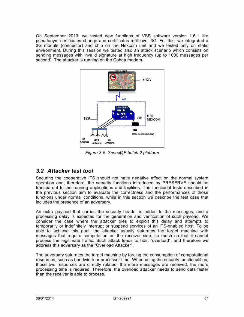
08/01/2014 IST-269994 57
On September 2013, we tested new functions of VSS software version 1.6.1 like pseudonym certificates change and certificates refill over 3G. For this, we integrated a 3G module (connector) and chip on the Nexcom unit and we tested only on static environment. During this session we tested also an attack scenario which consists on sending messages with invalid signature at high frequency (up to 1000 messages per second). The attacker is running on the Cohda modem.
Figure 3-5: Score@F batch 2 platform
3.2 Attacker test tool Securing the cooperative ITS should not have negative effect on the normal system operation and, therefore, the security functions introduced by PRESERVE should be transparent to the running applications and facilities. The functional tests described in the previous section aim to evaluate the correctness and the performances of those functions under normal conditions, while in this section we describe the test case that includes the presence of an adversary. An extra payload that carries the security header is added to the messages, and a processing delay is expected for the generation and verification of such payload. We consider the case where the attacker tries to exploit this delay and attempts to temporarily or indefinitely interrupt or suspend services of an ITS-enabled host. To be able to achieve this goal, the attacker usually saturates the target machine with messages that require computation on the receiver side, so much so that it cannot process the legitimate traffic. Such attack leads to host “overload”, and therefore we address this adversary as the “Overload Attacker”. The adversary saturates the target machine by forcing the consumption of computational resources, such as bandwidth or processor time. When using the security functionalities, those two resources are directly related: the more messages are received, the more processing time is required. Therefore, the overload attacker needs to send data faster than the receiver is able to process.

08/01/2014 IST-269994 58
To achieve this without deploying an expensive distributed denial-of-service attack over different machines, a single ITS station is deployed using a modified version of the PRESERVE VSS. Instead of running the CPU-intensive cryptographic operations needed to generate a valid signature, the modified version attaches an invalid, i.e., randomly generated, security header. This operation is orders of magnitude faster that the signature generation, and therefore it allows the adversary to overflow the receiver ITS. As a matter of fact, the receiver must still spend processor time to invalidate such forged header. During the normal operations, we enable an outsider ITS station to act as the overload attacker with the modified PRESERVE VSS. This device then starts broadcasting invalid messages to other ITS stations at a rate of 1000 Hz. We then evaluate the impact of such attack on the system by comparing the measurements of the packet processing time in the normal operations with the ones obtained during the attack. We consider the test successful if the performance degradation affects only minimally the applications and facilities.
4 Test results Table 4-1 shows the tests that were performed in car.
Test description Completed Notes
F-SIG-01
Generation of signed CAM/DENM messages
Yes Successful
F-SIG-01
Verification of signed CAM/DENM
Yes Successful
F-PSN-01
Pseudonym Change on request or at system startup
Yes Communication stack did not provide full implementation
F-PSN-02
Pseudonym Certificate Refill over 3G
Yes Failed, problem with certificate in openssl repository
F-PSN-02
Pseudonym Certificate Refill over 5G (via the RSU providing Internet connection)
No Not tested
A-SIG-04
DoS overload attack
Yes All packets successfully verified
A-CER-01
Invalid root certificate
No Not tested

08/01/2014 IST-269994 59
A-SIG-01
Attacker signs CAM with invalid signature
No Not tested
Table 4-1: JFT test status
4.1 Performance Analysis For the performance tests there were two Nexcom boxes, with each box sending to and receiving from the other box. The performance results described in this section concern a table-top test, that is to say that the Nexcom boxes were not in a vehicle, but stationary in a room. In order to distinguish between the two boxes, we will refer to them by their identifiers c341 and c342 from now on.
To analyze the performance indicators, there are two different log files that we look at. The first of these are the PCOM log files. These indicate which events happen in the libpreserve library, along with precise timestamps. The second set of log files are those of the Hitachi stack, which indicates packet sending and arrival times.
The results of all the tests performed on 10 September 2013 can be seen in Tables 4-2 and 4-3. Table 4-2 shows the analysis results from the PCOM log files and Table 4-3 shows the analysis results from the Hitachi stack log files. These correspond to measurement point 2 and measurement point 1 of figure 2-1 respectively. For each type of event, the table gives the minimum, maximum, and average time, as well as the jitter (average deviation from mean) and error rate. The last column gives the graph in which the results can be seen. The performance indicators that we use are signature generation delay (SGD), signature verification delay (SVD) and packet delay (PD), as can be seen in table 8-2.
Test Min (ms) Max (ms) Avg (ms) Jitter (ms)
Errors Figure
c341 SVD 27.24 242.42 32.98 3.81 0 Figure 4-1
c342 SVD 24.01 363.36 33.40 5.08 0 Figure 4-2
c341 SGD 1.71 26.48 2.46 0.299 0 Figure 4-3
c432 SGD 1.78 93.26 2.50 0.258 0 Figure 4-4
Table 4-2: PCOM log analysis results
Test Min (ms) Max (ms) Avg (ms) Jitter (ms)
Errors Figure
c341 SVD 27.46 242.82 33.20 3.63 0 Figure 4-5
c342 SVD 26.75 984.69 38.58 4.68 0 Figure 4-6
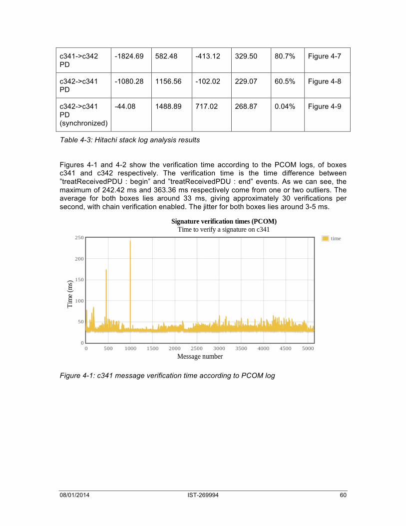
08/01/2014 IST-269994 60
c341->c342 PD
-1824.69 582.48 -413.12 329.50 80.7% Figure 4-7
c342->c341 PD
-1080.28 1156.56 -102.02 229.07 60.5% Figure 4-8
c342->c341 PD (synchronized)
-44.08 1488.89 717.02 268.87 0.04% Figure 4-9
Table 4-3: Hitachi stack log analysis results
Figures 4-1 and 4-2 show the verification time according to the PCOM logs, of boxes c341 and c342 respectively. The verification time is the time difference between ”treatReceivedPDU : begin” and ”treatReceivedPDU : end” events. As we can see, the maximum of 242.42 ms and 363.36 ms respectively come from one or two outliers. The average for both boxes lies around 33 ms, giving approximately 30 verifications per second, with chain verification enabled. The jitter for both boxes lies around 3-5 ms.
Figure 4-1: c341 message verification time according to PCOM log

08/01/2014 IST-269994 61
Figure 4-2: c342 message verification time according to PCOM log
Figures 4-3 and 4-4 show the signing time of boxes c341 and c342 respectively. This time, this is the difference between ”treatSendingPDU : begin” and ”treatSendingPDU : end” events in the PCOM logs. The maxima of 26.48 ms and 93.26 ms are again due to some outliers, with the average lying around the 2.50 ms. This gives approximately 400 signatures per second. The jitter is around 0.25 - 0.3 ms.
Next we look at performance according to the Hitachi stack logs. Figures 4-5 and 4-6 show the verification time of c341 and c342 respectively. The average verification times are 33.20 ms and 38.58, giving approximately 30 and 27 verifications per second.
Figure 4-3: c341 message signing time according to PCOM log

08/01/2014 IST-269994 62
Figure 4-4: c342 message signing time according to PCOM log
Figure 4-5: c341 message verification time according to Hitachi stack log

08/01/2014 IST-269994 63
Figure 4-6: c342 message verification time according to Hitachi stack log
Finally we can also look at packet delays, as the Hitachi stack logs indicate the timestamps of all packets that are sent and received. By looking at the contents of the packet, the sent packets can be matched with the received packets, and the time of flight can be calculated. Unfortunately, the timestamps in the packets are not fine-grained enough to uniquely identify which received packet matched which sent packet. This means that often a sent packet can be matched with multiple received packets. The results of these measurements can be seen in Figures 4-7 and 4-8.
Figure 4-7 shows the packet delay from c341 to c342, and Figure 4-8 shows the packet delay from c342 to c341. The mintime line indicates the time from the packet being sent to the first matched packet that is received, whereas the maxtime line shows the time until the last matched packet is received. In other words, they give the best case and worst case packet delays un- der the assumption that packets do not arrive in-order. The errors line gives points where packets are received before they are sent. This occurred due the clocks on the two Nexcom boxes not being synchronized. For c341, 80.7% of the messages were sent before they were received, for c342 this lies at 60.5%. This, along with the magnitude of the negative packet delays, indicates that there was a substantial deviation between the system clocks on the two boxes.
The results in Table 4-3 assume that the first matched packet is the correct one, so the packets arrive in order. Under this assumption, the minimum packet delay was -1824.69 ms for packets going from c341 to c342 and -1080.28 ms the other way around. The maxima were 582.48 ms and 1156.56 ms and the averages were -413.12 ms and -102.02 ms respectively. Finally, the jitter was 329.50 ms and 229.07 ms respectively. Unfortunately, the clock difference is not known, so it is impossible to draw any direct conclusions from these packet delays.
To see if this problem could be solved, the system clocks on the two boxes were synchronized with a remote server and NTP. The results of this can be seen in Figure 4-9. Here the minimum packet delay is -44.08 ms, the maximum is 1488.89 ms and the

08/01/2014 IST-269994 64
average is 717.02 ms, again assuming in-order packet arrival. The jitter in this case was 268.87 ms. These measurements give a more realistic view of the actual packet delays. Unfortunately there was still an error rate of 0.04%, meaning that there was still a small synchronization error between the clocks on the two systems. To get more accurate results, it would be best to synchronize the clocks to a high degree of accuracy, perhaps by using the GPS functionality of the Nexcom boxes.
Finally an attacker test was also performed, where a lot of messages were sent to see what would happen. An attacker tool sent signed messages at a high data rate to see what would happen. Over the course of 45.7 second, 6637 packets were sent, and all of these were successfully received and verified (without chain verification). Unfortunately the testing time with the attacker was limited, so no further test were done with this.
Figure 4-7. c341 → c342 packet delay according to Hitachi stack log
Figure 4-8. c342 → c341 packet delay according to Hitachi stack log

08/01/2014 IST-269994 65
Figure 4-9. c342 → c341 packet delay according to Hitachi stack log
5 Conclusion Only partial test results were made available during joint Score@F - PRESERVE test sessions. To complete all tests that are specified in the testing handbook more work needs to be done. As seen in Table 4-1, all tests that depend on pseudonym changes could not be done due to numerous issues. Furthermore, the performance tests could be extended and improved as well. Firstly, using the GPS to synchronize the system clocks between sending and receiving boxes would improve the packet delay measurements. Secondly, detailed time logging of all functions and subfunctions during signing/verifying and pseudonym changes would give better details in the current performance results and would allow measurements of for example the hash delay at measurement point 5.
PRESERVE VSS was tested on two different platforms from Score@F FOT (batch1 and batch2 as presented on figure 3-3).
FPGA-based VSS was functionality tested using the Denso IEEE 802.11p modem and VTC platform (batch1). Because of the absence of a cooperation agreement signed by all Score@F partners, the HSM prototype developed by PRESERVE (FPGA) could not be used in Score@F Field Operational Tests as planned.
Therefore, in July 2013, PRESERVE and Score@F has signed a MoU that covers the usage of a SW-only version of the VSS (without Escrypt’s libraries). Joint tests were organized in September 2013 for testing the core functions of the security system and to test on-line protocols for pseudonyms refilling and evaluate PRESERVE PKI performances.
The main results of these tests were to demonstrate the correct behaviour of the whole system in a realistic FOT environment (Yvelines-Versailles test site and test tracks), including vehicle stations equipped with PRESERVE VSS and other roadside stations not equipped with security system. We conducted functional testing and attack

08/01/2014 IST-269994 66
scenarios. This report summarizes the results of security functional tests and gives first evaluations of performance measurements, mainly signature generation/verification delays and end-to-end latency.
These results show that a software security solution is insufficient for ITS security requirements. A dedicated hardware module for security solution is needed. That’s why PRESERVE defines an ASIC for securing V2X systems. The ASIC will be tested on next trials scheduled in 2014 and later.
6 Bibliography
[1] FESTA / FOT-NET. "FESTA Handbook Version 4." 2011.
[2] Robert Schmidt, Bernhard Kloiber, Florian Schüttler, Thomas Strang. "Degradation of Communication Range in VANETs caused by Interference 2.0 - Real-World Experiment." 3rd International Workshop on Communication Technologies for Vehicles (Nets4Cars). Oberpfaffenhofen, Germany, 2011.
[3] Car-2-Car Communication Consortium, "C2C-CC Public Key Infrastructure Memo," Report, February 2011.
[4] N. Bißmeyer, J. Petit, D. Estor, M. Sall, J.P. Stotz, M. Feiri, R. Moalla, S. Dietzel,
“PRESERVE D1.2 V2X Security Architecture,” PRESERVE consortium, Deliverable, November 2011.
[5] Drive C2X Deliverable D25.1: DRIVE C2X test environment: specification, implementation and tests.
[6] VSS Kit installation manuel.
[7] PRESERVE Technical Report 4: V2X Security Testing Handbook, v1.1, 2013-09-09.
[8] Score@F Final Event presentations on website www.scoref.fr
[9] Score@F paper on Fault Tolerant C-ITS for Road Safety, Gérard Segarra (Renault), Alain Servel (PSA), Sue Bai (Honda), ITS WC 2013, Tokyo
[10] Evaluation of PRESERVE V2X security trials in the French FOT Score@F, Rim Moalla, Brigitte Lonc, Gerard Segarra, Marcello Lagana, Panagiotis Papadimitratos, Jonathan Petit (to appear in TRA2014)
[11] ETSI TS 102 539-1 Road Hazard Signalling application requirements


![* 3-9 0 3-6 7 3-0 5 * CAMERA CONTROL UNIT CCU …pdf.crse.com/manuals/3903673051.pdfCAMERA CONTROL UNIT CCU-790/790P OPERATION MANUAL [English] 1st Edition (Revised 4) * 3-9 0 3-6](https://static.fdocuments.net/doc/165x107/5ae3b1837f8b9a0d7d8dfa82/-3-9-0-3-6-7-3-0-5-camera-control-unit-ccu-pdfcrsecommanuals-control-unit.jpg)