PRELIMINARY GEOTECHNICAL INVESTIGATION FIVE … Report.pdf · torti gallas and partners, inc. 1...
46
1971 West 12th Avenue | Denver, Colorado 80204 | Phone: 303-825-0777 | Fax: 303-825-4252 PRELIMINARY GEOTECHNICAL INVESTIGATION FIVE PARCELS NEAR WEST 71 ST AVENUE AND HOOKER STREET NORTHWEST CORRIDOR CATALYTIC PROJECT ADAMS COUNTY HOUSING AUTHORITY PROPERTIES AT WESTMINSTER STATION WESTMINSTER, COLORADO Prepared For: TORTI GALLAS AND PARTNERS, INC. 523 West 6 th Street, Suite 212 Las Angeles, California 90014 Attention: Martin Leitner Neal Payton Project No. DN47,420-115 September 16, 2014
Transcript of PRELIMINARY GEOTECHNICAL INVESTIGATION FIVE … Report.pdf · torti gallas and partners, inc. 1...

1971 West 12th Avenue | Denver, Colorado 80204 | Phone: 303-825-0777 | Fax: 303-825-4252
PRELIMINARY GEOTECHNICAL INVESTIGATION
FIVE PARCELS NEAR WEST 71ST AVENUE AND HOOKER STREET
NORTHWEST CORRIDOR CATALYTIC PROJECTADAMS COUNTY HOUSING AUTHORITY
PROPERTIES AT WESTMINSTER STATIONWESTMINSTER, COLORADO
Prepared For:
TORTI GALLAS AND PARTNERS, INC. 523 West 6th Street, Suite 212
Las Angeles, California 90014
Attention: Martin Leitner Neal Payton
Project No. DN47,420-115
September 16, 2014

TORTI GALLAS AND PARTNERS, INC. WESTMINSTER STATION HOUSING CTL | T PROJECT NO. DN47,420-115 S:\PROJECTS\47400\DN47420.000\115\2. Reports\R1\DN47420-115-R1.docx
TABLE OF CONTENTS
SCOPE ................................................................................................................. 1
SUMMARY ........................................................................................................... 1
SITE CONDITIONS AND PROPOSED CONSTRUCTION ................................... 3
INVESTIGATION .................................................................................................. 5
SUBSURFACE CONDITIONS .............................................................................. 6 Fill .............................................................................................................. 6 Natural Clay, Sand and Gravel ................................................................... 6 Bedrock ...................................................................................................... 7 Groundwater .............................................................................................. 7 Seismicity ................................................................................................... 8
ESTIMATED POTENTIAL SETTLEMENT AND HEAVE ...................................... 8
SITE DEVELOPMENT CONSIDERATIONS ......................................................... 8 Existing Fill and Demolition ........................................................................ 9 Excavation .................................................................................................. 9 Fill and Backfill ......................................................................................... 10 Sub-Excavation ........................................................................................ 11 Pavements ............................................................................................... 14
BUILDING CONSTRUCTION CONSIDERATIONS ............................................ 14 Foundations ............................................................................................. 14 Slab-On-Grade Construction .................................................................... 15 Below-Grade Areas .................................................................................. 16 Concrete ................................................................................................... 17 Surface Drainage ..................................................................................... 17
RECOMMENDED FUTURE INVESTIGATIONS ................................................. 18
LIMITATIONS ..................................................................................................... 19
FIG. 1 – LOCATIONS OF EXPLORATORY BORINGS
FIG. 2 – CONCEPTUAL SUB-EXCAVATION PROFILE
APPENDIX A – SUMMARY LOGE OF EXPLORATORY BORINGS
APPENDIX B – LABORATORY TEST RESULTS
APPENDIX C – GUIDELINE SITE GRADING SPECIFICATIONS

TORTI GALLAS AND PARTNERS, INC. 1 WESTMINSTER STATION HOUSING CTL | T PROJECT NO. DN47,420-115 S:\PROJECTS\47400\DN47420.000\115\2. Reports\R1\DN47420-115-R1.docx
SCOPE
This report presents the results of our Preliminary Geotechnical Investiga-
tion for five parcels owned by the Adams County Housing Authority located
northwest, northeast and southeast of West 71st Avenue and Hooker Street in
Westminster, Colorado (Fig. 1). The purpose of our investigation was to evaluate
the subsurface conditions to assist in operation and redevelopment of the proper-
ties in the future. This letter includes descriptions of subsurface conditions and
groundwater levels found in our exploratory borings and discussions of site
development and building and pavement construction as influenced by geotech-
nical considerations. Evaluation of the property for the possible presence of
potentially hazardous materials (Environmental Site Assessment) was not in-
cluded in the scope.
This report was prepared from site reconnaissance and data developed
during field exploration, field and laboratory testing, engineering analysis of field
and laboratory data, previous investigations and experience with similar condi-
tions and projects. The preliminary recommendations presented in the report are
intended for evaluation and planning purposes only. Additional investigation will
be necessary to provide geotechnical design recommendations for specific
buildings, pavements and other improvements. A summary of our conclusions is
presented below with more complete descriptions included in the report.
SUMMARY
1. The site is judged suitable for redevelopment. The primary ge-otechnical concerns are expansive soils and bedrock and the pres-ence of existing structures and fill. No geotechnical constraints were identified which, in our opinion, preclude redevelopment.
2. Strata found in our borings consisted of nil to about 5 feet of clay fill
and/or 3 to 26.5 feet of natural clay, sand and gravel underlain by claystone and sandstone bedrock. About 3 to 6 inches of asphalt

TORTI GALLAS AND PARTNERS, INC. 2 WESTMINSTER STATION HOUSING CTL | T PROJECT NO. DN47,420-115 S:\PROJECTS\47400\DN47420.000\115\2. Reports\R1\DN47420-115-R1.docx
and 3 to 6 inches of base course were penetrated at the ground surface in five borings drilled in pavement areas. Testing indicated the soils and bedrock are predominantly non-expansive or low swelling. Planning and design of the proposed construction should consider the impacts of expansive soils and bedrock.
3. Groundwater was encountered during drilling in 7 borings at depths of about 13 to 34 feet. When the holes were checked after drilling, water levels were measured at depths of about 13 to 24.5 feet or relative elevations 83.5 to 94 feet. We do not expect groundwater will affect construction unless relatively deep basements or drilled pier foundations are used for buildings. Basements are suitable if planned to be at least 3 feet, and preferably 5 feet, above ground-water levels. Groundwater may be encountered during utility instal-lation and temporary construction dewatering may be necessary. Water levels may fluctuate seasonally and rise in response to pre-cipitation and landscape irrigation.
4. Our investigation indicates expansive soil and bedrock and existing
fill are present at depths likely to influence the performance of shal-low foundations and slab-on-grade floors. Expansive materials can cause heave upon wetting. We estimate potential heave up to about 2 inches. The site is judged to have low to moderate risk of damage due to expansive soil and bedrock. Settlement is also pos-sible for improvements constructed over poorly compacted fill.
5. We believe sub-excavation can be used to reduce potential future movements, provide more uniform support conditions and likely al-low use of shallow foundations and slab-on-grade floors. Based on preliminary data, we believe it would be beneficial to sub-excavate to a depth of 7 feet below grade for most of the site. Deeper sub-excavation to a depth of 12 feet below grade or 5 to 10 feet below basement foundations can be used where claystone is shallow. If potential heave is not mitigated, most structures will likely require use of drilled pier foundations and some may need structurally sup-ported basement floors. Perimeter drains should be used around below-grade spaces.
6. Calculated potential heave at the anticipated below-grade levels was up to about 1 inch. Risk of poor lower-level slab-on-grade floor performance varies from low to moderate. The risk rating should be lower after sub-excavation, and should allow use of slab-on-grade floors on most or all parcels.

TORTI GALLAS AND PARTNERS, INC. 3 WESTMINSTER STATION HOUSING CTL | T PROJECT NO. DN47,420-115 S:\PROJECTS\47400\DN47420.000\115\2. Reports\R1\DN47420-115-R1.docx
7. Pavement subgrade soils are likely to be derived of clay, which is considered poor subgrade material. Based on the City of Westmin-ster standards and specifications, we anticipate parking lots and access drives will require 5 to 6 inches of full-depth asphalt or con-crete or an equivalent composite section. Sub-excavation can be considered below pavements to enhance performance. A site-specific design-level subgrade investigation should be done prior to development.
8. Control of surface and subsurface drainage will be critical to the performance of foundations, slabs-on-grade and pavements. Over-all surface drainage should be designed to provide rapid run-off of surface water away from structures and off pavements and flat-work. Water should not be allowed to pond near the crests of slopes, near structures or on pavements and flatwork.
SITE CONDITIONS AND PROPOSED CONSTRUCTION
The site consists of five parcels or ten lots totaling about 6.5 acres located
northwest, northeast and southeast of West 71st Avenue and Hooker Street in
Westminster, Colorado (Fig. 1 and Photo 1). The properties are owned by the
Adams County Housing Authority and are currently occupied by multifamily
residential developments. The site is planned for transportation-oriented devel-
opment as part of Westminster Station. The surrounding areas have residential,
commercial and mixed-use developments. The ground surface is generally flat,
with a gentle slope toward Little Dry Creek which is about ¼-mile southwest.

TORTI GALLAS AND PARTNERS, INC. 4 WESTMINSTER STATION HOUSING CTL | T PROJECT NO. DN47,420-115 S:\PROJECTS\47400\DN47420.000\115\2. Reports\R1\DN47420-115-R1.docx
Photo 1 – Google Earth© Aerial Site Photo, October 2013
Each parcel except the far east is developed with existing two or three-
story apartment buildings (which were constructed between 1961 and 1974) and
associated pavements and utilities. The east parcel has a one-story single-family
residence on the far north lot and the remaining lots are vacant. Structures were
demolished from the vacant parcels. We do not know if any of the previous or
existing structures contain basements or below-grade areas. Ground cover in the
developed areas consists of buildings, asphalt pavement, concrete flatwork, and
landscaping (irrigated grass, bushes and trees). The southern portion of the far
east parcel is undeveloped and the ground is sparsely covered with grasses,
weeds, bushes, building materials and debris.
Development plans are not available. At this time, we understand the site
is being master planned for retail, commercial and medium to high density hous-
ing. Existing structures, pavements, flatwork and utilities will be demolished to
allow the new construction. Because the surrounding land is developed, we do
not anticipate significant cut and fill grading will be necessary to redevelop the
site.

TORTI GALLAS AND PARTNERS, INC. 5 WESTMINSTER STATION HOUSING CTL | T PROJECT NO. DN47,420-115 S:\PROJECTS\47400\DN47420.000\115\2. Reports\R1\DN47420-115-R1.docx
INVESTIGATION
We investigated subsurface conditions on August 6 and 7, 2014 by drilling
and sampling 10 exploratory borings at the approximate locations shown on Fig.
1. The borings were drilled to depths of 25 to 40 feet below the existing ground
surface using 4-inch diameter, continuous-flight solid-stem auger and a truck-
mounted CME-55 drill rig. Samples were obtained at 5-foot intervals using a 2.5-
inch diameter (O.D.) modified California barrel sampler driven by blows of an
automatic 140-pound hammer falling 30 inches. Our field representative was
present to observe drilling operations, log the strata encountered, obtain samples
for laboratory tests and survey the boring elevations relative to the temporary
benchmark shown on Fig. 1 (existing sanitary sewer manhole rim, assumed
elevation 100.0 feet). If survey datum is provided, we can revise our boring
elevations to reflect that datum. Upon completion of drilling, the drilling areas
were cleaned and hand-slotted PVC pipe was installed in the holes to allow
delayed groundwater measurements. In paved areas, the ground surface was
restored using asphalt cold-patch. Summary logs of the exploratory borings
including results of field penetration resistance tests and a portion of laboratory
test results are presented in Appendix A.
Samples were returned to our laboratory where they were examined and
testing was assigned. Laboratory tests included moisture content, dry density,
percent silt and clay-sized particles (passing No. 200 sieve), Atterberg limits,
unconfined compressive strength, swell-consolidation and water-soluble sulfate
concentration. Laboratory test results are presented in Appendix B and summa-
rized on Table B-I.

TORTI GALLAS AND PARTNERS, INC. 6 WESTMINSTER STATION HOUSING CTL | T PROJECT NO. DN47,420-115 S:\PROJECTS\47400\DN47420.000\115\2. Reports\R1\DN47420-115-R1.docx
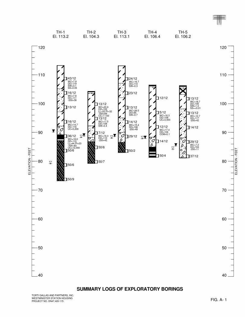
SUBSURFACE CONDITIONS
Strata encountered in our exploratory borings consisted of nil to about 5
feet of sandy clay fill and/or 3 to 26.5 feet of natural clay, sand and gravel under-
lain by claystone and sandstone bedrock to the maximum explored depth of 40
feet. About 3 to 6 inches of asphalt over 3 to 6 inches of base course were
penetrated at the ground surface in five borings drilled in pavement areas (TH-2,
TH-4, TH-5, TH-6 and TH-10). Some pertinent engineering characteristics of the
soil and bedrock are described in the following paragraphs.
Fill
We found about 3 and 5 feet of sandy clay fill at the ground surface in two
borings, TH-5 and TH-10, respectively. The fill was darker brown than the natural
soils, but was of similar composition as the natural sandy clay. The fill is likely
associated with construction of the existing improvements. The fill was stiff based
on the result of a field penetration resistance test. A sandy clay fill sample
swelled 0.6 percent when wetted under an applied pressure of 500 psf.
Natural Clay, Sand and Gravel
Natural soils generally consisted of 3 to 23 feet of sandy to very sandy,
silty clay and/or silty to very clayey sand over nil to 9.5 feet of slightly silty to
clayey sand and gravel. The sand and gravel caved below groundwater at a
depth of about 15 feet in one boring, TH-10. The clay was medium stiff to very
stiff and the sand and gravel was loose to dense. One sandy clay sample com-
pressed 0.1 percent and eight swelled 0.3 to 3.1 percent when wetted. We
estimated load-back swell pressures of about 1,400 to 7,000 psf on 4 samples.
Three clay samples had unconfined compressive strengths of about 3,400 to
7,100 psf. Two clay samples contained 55 and 69 percent fines and showed

TORTI GALLAS AND PARTNERS, INC. 7 WESTMINSTER STATION HOUSING CTL | T PROJECT NO. DN47,420-115 S:\PROJECTS\47400\DN47420.000\115\2. Reports\R1\DN47420-115-R1.docx
moderate to high plasticity with liquid limits of 36 and 52 and plasticity indices of
15 and 32. Eight sand samples had 11 to 49 percent silt and clay-sized particles.
Bedrock
Bedrock consisted of claystone and interbedded claystone/sandstone and
was found in all borings except TH-5 at depths of about 3 to 26.5 feet or eleva-
tions 80.5 to 105 feet. The bedrock was medium hard to very hard. Four bedrock
samples swelled 0.6 to 1.1 percent when wetted and we estimate load-back swell
pressures of approximately 5,000 to 8,100 psf on 3 samples. Four samples
exhibited unconfined compressive strengths of about 9,400 to 13,800 psf. Two
claystone samples had 83 and 95 percent fines and showed moderate to very
high plasticity with liquid limits of 44 and 75 and plasticity indices of 23 and 45.
Three interbedded bedrock samples contained 23 to 43 percent silt and clay-
sized particles.
Groundwater
Groundwater was encountered during drilling in 7 borings at depths of
about 13 to 34 feet below grade. When the holes were checked after drilling on
September 10, 2014, water levels were measured in all 8 borings at depths of
about 12.7 to 24.5 feet or relative elevations 83.5 to 93.8 feet. We do not expect
groundwater will affect construction unless relatively deep basements or drilled
pier foundations are used for buildings. Basements are suitable if planned to be
at least 3 feet, and preferably 5 feet, above groundwater levels. Groundwater
may be encountered during utility installation and temporary construction de-
watering may be necessary. Water levels may fluctuate seasonally and rise in
response to precipitation and landscape irrigation.

TORTI GALLAS AND PARTNERS, INC. 8 WESTMINSTER STATION HOUSING CTL | T PROJECT NO. DN47,420-115 S:\PROJECTS\47400\DN47420.000\115\2. Reports\R1\DN47420-115-R1.docx
Seismicity
The soils and bedrock are not expected to respond unusually to seismic
activity. According to the 2009 International Building Code (IBC, Standard Pene-
tration Resistance method of Section 1613.5.2) and based upon the results of
our investigation, we judge the site classifies as Seismic Site Class C. The
subsurface conditions indicate nil susceptibility to liquefaction. Only minor dam-
age to relatively new, properly designed and constructed structures would be
expected with a major seismic event. Wind loads typically govern dynamic
structural design in this area.
ESTIMATED POTENTIAL SETTLEMENT AND HEAVE
We estimate 1 to 2 inches of potential ground heave based on 15 to 20-
foot depth of wetting below existing grade, considered typical for this type of
project. Shallow foundations and slabs constructed on poorly compacted fill may
experience settlement. It is not certain these movements will occur. Overall, we
found relatively favorable conditions that lead us to judge that most of the site is
low or moderate risk of damage caused by expansive soil and bedrock. Potential
movements can be reduced and more uniform support conditions can be provid-
ed with shallow-depth sub-excavation of about 7 to 12 feet below existing grades.
We judge the majority of the site can use sub-excavation to a depth of 7 feet, and
the far east parcel can be sub-excavated 12 feet or 5 to 10 feet below basement
foundations due to shallow claystone, as discussed later in this report.
SITE DEVELOPMENT CONSIDERATIONS
The site is judged suitable for redevelopment. The primary geotechnical
concerns are expansive soils and bedrock and the presence of existing struc-
tures and fill. These concerns can be mitigated with proper investigation, plan-
TORTI GALLAS AND PARTNERS, INC. 9 WESTMINSTER STATION HOUSING CTL | T PROJECT NO. DN47,420-115 S:\PROJECTS\47400\DN47420.000\115\2. Reports\R1\DN47420-115-R1.docx
ning, engineering, design, and construction. No geotechnical constraints were
identified which, in our opinion, preclude redevelopment.
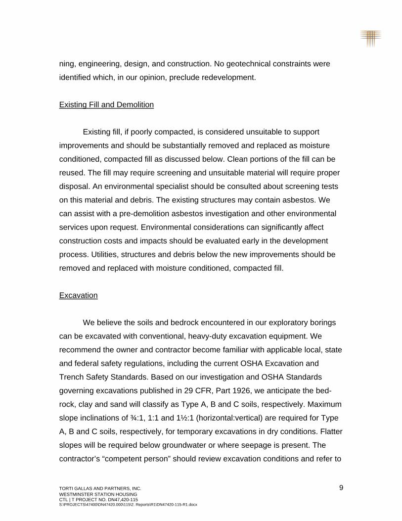
Existing Fill and Demolition
Existing fill, if poorly compacted, is considered unsuitable to support
improvements and should be substantially removed and replaced as moisture
conditioned, compacted fill as discussed below. Clean portions of the fill can be
reused. The fill may require screening and unsuitable material will require proper
disposal. An environmental specialist should be consulted about screening tests
on this material and debris. The existing structures may contain asbestos. We
can assist with a pre-demolition asbestos investigation and other environmental
services upon request. Environmental considerations can significantly affect
construction costs and impacts should be evaluated early in the development
process. Utilities, structures and debris below the new improvements should be
removed and replaced with moisture conditioned, compacted fill.
Excavation
We believe the soils and bedrock encountered in our exploratory borings
can be excavated with conventional, heavy-duty excavation equipment. We
recommend the owner and contractor become familiar with applicable local, state
and federal safety regulations, including the current OSHA Excavation and
Trench Safety Standards. Based on our investigation and OSHA Standards
governing excavations published in 29 CFR, Part 1926, we anticipate the bed-
rock, clay and sand will classify as Type A, B and C soils, respectively. Maximum
slope inclinations of ¾:1, 1:1 and 1½:1 (horizontal:vertical) are required for Type
A, B and C soils, respectively, for temporary excavations in dry conditions. Flatter
slopes will be required below groundwater or where seepage is present. The
contractor’s “competent person” should review excavation conditions and refer to

TORTI GALLAS AND PARTNERS, INC. 10 WESTMINSTER STATION HOUSING CTL | T PROJECT NO. DN47,420-115 S:\PROJECTS\47400\DN47420.000\115\2. Reports\R1\DN47420-115-R1.docx
OSHA Standards when worker exposure is anticipated. Stockpiles of soil and
equipment should not be placed within a horizontal distance equal to one-half the
excavation depth, from the edge of the excavation. A Professional Engineer
should design excavations greater than 20 feet deep.
Fill and Backfill
The on-site soils are generally suitable for reuse as new fill, provided they
are substantially free of debris, vegetation/organics and other deleterious materi-
als. Soil and bedrock particles larger than 3 inches in diameter should not be
used for fill unless broken down. If imported fill is necessary, it should ideally
have maximum particle size of 2 inches, less than 45 percent passing a No. 200
sieve, a liquid limit less than 30 and a plasticity index less than 15. Potential fill
materials should be submitted to our office for approval prior to importing to the
site.
Prior to fill placement, debris, vegetation/organics and other deleterious
materials should be substantially removed from areas to receive fill. Deep re-
moval may be necessary where tree roots are present. The surface to be filled
should be scarified to a depth of at least 8 inches, moisture conditioned, and
compacted to the criteria below. Subsequent fill should be placed in thin (8
inches or less) loose lifts, moisture conditioned to between optimum and 3
percent above optimum moisture content for clay or within 2 percent of optimum
moisture content for sand, and compacted to at least 95 percent of standard
Proctor maximum dry density (ASTM D 698). Guideline grading specifications
are presented in Appendix C.
Water and sewer lines are usually constructed below pavements and
flatwork. Compaction of trench backfill can have a significant effect on the life
and serviceability of floor slabs, pavements, and exterior flatwork. We recom-
TORTI GALLAS AND PARTNERS, INC. 11 WESTMINSTER STATION HOUSING CTL | T PROJECT NO. DN47,420-115 S:\PROJECTS\47400\DN47420.000\115\2. Reports\R1\DN47420-115-R1.docx
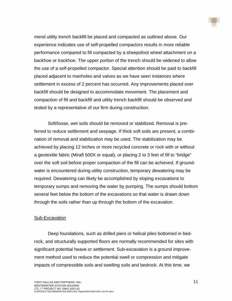
mend utility trench backfill be placed and compacted as outlined above. Our
experience indicates use of self-propelled compactors results in more reliable
performance compared to fill compacted by a sheepsfoot wheel attachment on a
backhoe or trackhoe. The upper portion of the trench should be widened to allow
the use of a self-propelled compactor. Special attention should be paid to backfill
placed adjacent to manholes and valves as we have seen instances where
settlement in excess of 2 percent has occurred. Any improvements placed over
backfill should be designed to accommodate movement. The placement and
compaction of fill and backfill and utility trench backfill should be observed and
tested by a representative of our firm during construction.
Soft/loose, wet soils should be removed or stabilized. Removal is pre-
ferred to reduce settlement and seepage. If thick soft soils are present, a combi-
nation of removal and stabilization may be used. The stabilization may be
achieved by placing 12 inches or more recycled concrete or rock with or without
a geotextile fabric (Mirafi 500X or equal), or placing 2 to 3 feet of fill to “bridge”
over the soft soil before proper compaction of the fill can be achieved. If ground-
water is encountered during utility construction, temporary dewatering may be
required. Dewatering can likely be accomplished by sloping excavations to
temporary sumps and removing the water by pumping. The sumps should bottom
several feet below the bottom of the excavations so that water is drawn down
through the soils rather than up through the bottom of the excavation.
Sub-Excavation
Deep foundations, such as drilled piers or helical piles bottomed in bed-
rock, and structurally supported floors are normally recommended for sites with
significant potential heave or settlement. Sub-excavation is a ground improve-
ment method used to reduce the potential swell or compression and mitigate
impacts of compressible soils and swelling soils and bedrock. At this time, we
TORTI GALLAS AND PARTNERS, INC. 12 WESTMINSTER STATION HOUSING CTL | T PROJECT NO. DN47,420-115 S:\PROJECTS\47400\DN47420.000\115\2. Reports\R1\DN47420-115-R1.docx
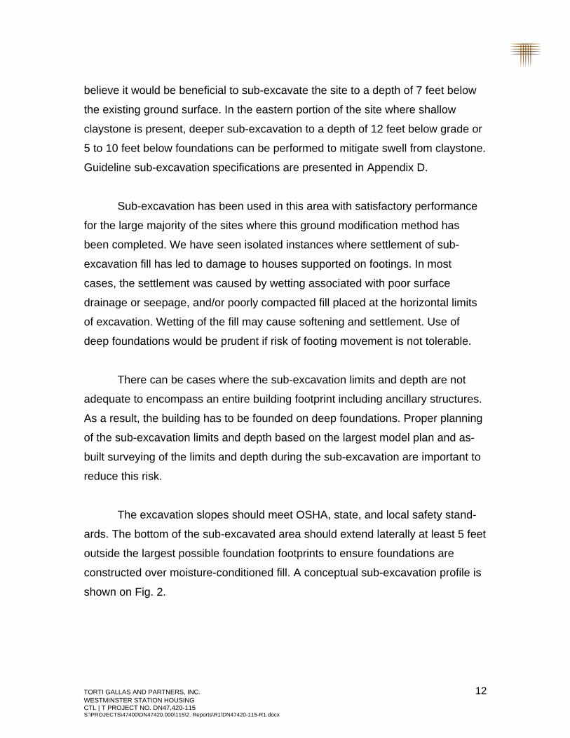
believe it would be beneficial to sub-excavate the site to a depth of 7 feet below
the existing ground surface. In the eastern portion of the site where shallow
claystone is present, deeper sub-excavation to a depth of 12 feet below grade or
5 to 10 feet below foundations can be performed to mitigate swell from claystone.
Guideline sub-excavation specifications are presented in Appendix D.
Sub-excavation has been used in this area with satisfactory performance
for the large majority of the sites where this ground modification method has
been completed. We have seen isolated instances where settlement of sub-
excavation fill has led to damage to houses supported on footings. In most
cases, the settlement was caused by wetting associated with poor surface
drainage or seepage, and/or poorly compacted fill placed at the horizontal limits
of excavation. Wetting of the fill may cause softening and settlement. Use of
deep foundations would be prudent if risk of footing movement is not tolerable.
There can be cases where the sub-excavation limits and depth are not
adequate to encompass an entire building footprint including ancillary structures.
As a result, the building has to be founded on deep foundations. Proper planning
of the sub-excavation limits and depth based on the largest model plan and as-
built surveying of the limits and depth during the sub-excavation are important to
reduce this risk.
The excavation slopes should meet OSHA, state, and local safety stand-
ards. The bottom of the sub-excavated area should extend laterally at least 5 feet
outside the largest possible foundation footprints to ensure foundations are
constructed over moisture-conditioned fill. A conceptual sub-excavation profile is
shown on Fig. 2.

TORTI GALLAS AND PARTNERS, INC. 13 WESTMINSTER STATION HOUSING CTL | T PROJECT NO. DN47,420-115 S:\PROJECTS\47400\DN47420.000\115\2. Reports\R1\DN47420-115-R1.docx
The excavation contractor should be chosen carefully to verify they have
experience with fill placement at above-optimum moisture and have the neces-
sary mixing and compaction equipment. The contractor should provide a con-
struction disc to break down fill materials and anticipate use of push-pull scraper
operations and dozer assistance. The operation will be relatively slow. In order
for the procedure to be performed properly, close contractor control of fill place-
ment to specifications is required. Sub-excavation fill should be moisture-
conditioned between optimum moisture content and 3 percent above optimum
with an average test moisture content each day of at least 1 percent above
optimum. Fill should be compacted to at least 95 percent of standard Proctor
maximum dry density.
Special precautions should be taken for compaction of fill at corners,
access ramps, and along the perimeters of the sub-excavation as large compac-
tion equipment cannot easily reach these areas. Our representative should
observe placement procedures and test compaction of the fill on a nearly full-time
basis. The swell of the moisture-conditioned fill should be tested during and after
the fill placement.
If the fill dries excessively prior to construction, it may be necessary to re-
work the upper drier materials just prior to constructing foundations. We judge
the fill should retain adequate moisture for about two years and can check mois-
ture conditions in each excavation as construction progresses, if requested.
Sub-excavation and replacement with low swell fill will likely allow use of
shallow footing or post-tensioned slab-on-grade foundation systems for lightly to
moderately loaded structures and enhance performance of slab-on-grade floors.
Sub-excavation will also enhance performance of concrete flatwork (driveways
and sidewalks) and pavements, potentially reducing maintenance costs. We
recommend a surveyor document the actual limits of the treatment, and create

TORTI GALLAS AND PARTNERS, INC. 14 WESTMINSTER STATION HOUSING CTL | T PROJECT NO. DN47,420-115 S:\PROJECTS\47400\DN47420.000\115\2. Reports\R1\DN47420-115-R1.docx
"as-built" plans. These plans should be provided to the civil/surveyor so that they
can verify that each building is over the treated area. The "treated area" stops at
the toe of the deep sub-excavation slope. It would be prudent to show the hori-
zontal limits and bottom elevation of treatment on plans.
Pavements
Existing fill will need to be completely removed below pavements for the
best performance. If left in place, geogrid can be considered to help bridge
anomalies in the fill. Pavement subgrade soils are likely to be derived of clay,
which is considered relatively poor subgrade material. Based on the City of
Westminster standards and specifications, we anticipate parking lots and access
drives will require 5 to 6 inches of full-depth asphalt or portland cement concrete.
An equivalent composite section can be used consisting of 4 inches of asphalt
over 8 inches of base course. For public roadways, the City may require shallow-
depth sub-excavation to depths of 1 to 3 feet to mitigate potential heave caused
by swelling subgrade. A design-level subgrade investigation should be done prior
to paving.
BUILDING CONSTRUCTION CONSIDERATIONS
The following discussions are preliminary and are not intended for design
or construction. Design-level investigation(s) should be performed once plans are
more developed and proposed building locations and floor elevations are known.
Foundations
Site soils generally include expansive soils and bedrock at depths likely to
affect foundation performance. Deep foundations are typically used where swell-
ing soil and bedrock are encountered, or foundation loads are moderate to high.

TORTI GALLAS AND PARTNERS, INC. 15 WESTMINSTER STATION HOUSING CTL | T PROJECT NO. DN47,420-115 S:\PROJECTS\47400\DN47420.000\115\2. Reports\R1\DN47420-115-R1.docx
Use of drilled piers will be challenging in parts of the site due to groundwater,
caving sand and gravel, and deep bedrock in some areas. Helical piles bottomed
in the natural sand and gravel are a suitable deep-foundation alternative.
We believe sub-excavation could allow use of footing or post-tensioned
slab-on-grade foundations for lightly to moderately loaded structures, as dis-
cussed previously. Large buildings may impose moderate or heavy foundation
loads which may require comparatively high allowable footing design pressures
and/or larger footings. Mat foundations are gaining interest in this area for mid-
rise structures with column loads of about 200 to 600 kips. Bearing capacity for
moderately to heavily loaded foundations may be limited by clay layers which can
consolidate over a period of months or years upon additional loading as pore
water pressure slowly dissipates.
Slab-On-Grade Construction
The choice of floor support methods should depend on the tolerance for
movement. The use of slab-on-grade floors should be limited to areas where
potential movements are judged to be low to moderate. We judge slab perfor-
mance risk will be low with minor sub-excavation. The performance of garage
floors, driveways, sidewalks, and other surface flatwork installed outside sub-
excavated areas may be erratic at this site. Shallower sub-excavation of 3 to 6
feet can be considered in these areas.
The following precautions will be required to reduce the potential for dam-
age due to movement of slabs-on-grade placed at this site:
1. Isolation of the slab from foundation walls, columns or other slab penetrations;
2. Voiding of interior partition walls to allow for slab movement without transferring movement to the structures;
TORTI GALLAS AND PARTNERS, INC. 16 WESTMINSTER STATION HOUSING CTL | T PROJECT NO. DN47,420-115 S:\PROJECTS\47400\DN47420.000\115\2. Reports\R1\DN47420-115-R1.docx
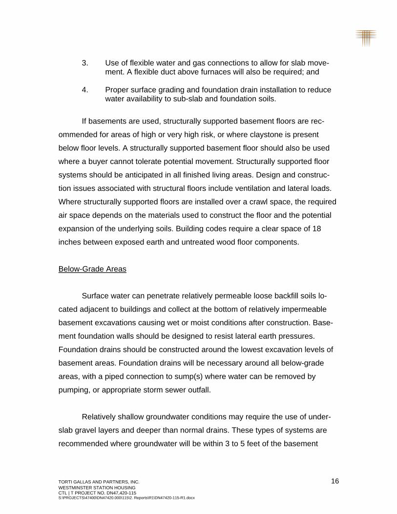
3. Use of flexible water and gas connections to allow for slab move-ment. A flexible duct above furnaces will also be required; and
4. Proper surface grading and foundation drain installation to reduce water availability to sub-slab and foundation soils.
If basements are used, structurally supported basement floors are rec-
ommended for areas of high or very high risk, or where claystone is present
below floor levels. A structurally supported basement floor should also be used
where a buyer cannot tolerate potential movement. Structurally supported floor
systems should be anticipated in all finished living areas. Design and construc-
tion issues associated with structural floors include ventilation and lateral loads.
Where structurally supported floors are installed over a crawl space, the required
air space depends on the materials used to construct the floor and the potential
expansion of the underlying soils. Building codes require a clear space of 18
inches between exposed earth and untreated wood floor components.
Below-Grade Areas
Surface water can penetrate relatively permeable loose backfill soils lo-
cated adjacent to buildings and collect at the bottom of relatively impermeable
basement excavations causing wet or moist conditions after construction. Base-
ment foundation walls should be designed to resist lateral earth pressures.
Foundation drains should be constructed around the lowest excavation levels of
basement areas. Foundation drains will be necessary around all below-grade
areas, with a piped connection to sump(s) where water can be removed by
pumping, or appropriate storm sewer outfall.
Relatively shallow groundwater conditions may require the use of under-
slab gravel layers and deeper than normal drains. These types of systems are
recommended where groundwater will be within 3 to 5 feet of the basement

TORTI GALLAS AND PARTNERS, INC. 17 WESTMINSTER STATION HOUSING CTL | T PROJECT NO. DN47,420-115 S:\PROJECTS\47400\DN47420.000\115\2. Reports\R1\DN47420-115-R1.docx
excavation. We recommend basement level construction be limited to a minimum
of 3 feet, and preferably 5 feet, above groundwater levels.
Concrete
Concrete in contact with soil can be subject to sulfate attack. We meas-
ured water-soluble sulfate concentrations of 0.05 percent in three samples from
this site. For this level of sulfate concentration, ACI 332-08 Code Requirements
for Residential Concrete indicates there are no special requirements for sulfate
resistance. Superficial damage may occur to the exposed surfaces of highly
permeable concrete, even though sulfate levels are relatively low. To control this
risk and to resist freeze-thaw deterioration, the water-to-cementitious materials
ratio should not exceed 0.50 for concrete in contact with soils that are likely to
stay moist due to surface drainage or high water tables. Concrete in the frost
zone should have a total air content of 6 percent ± 1.5 percent. We advocate all
foundation walls and grade beams in contact with the subsoils be damp-proofed.
Surface Drainage
The performance of foundations, floors, pavements and other improve-
ments is affected by moisture changes within the soil and bedrock. This is largely
influenced by surface drainage. When developing an overall drainage scheme,
consideration should be given to drainage around each structure. The ground
surface around the buildings should be sloped to provide positive drainage away
from the foundation. We recommend a slope of at least 5 percent for the first 10
feet surrounding each building, where practical. If the distance between buildings
is less than 20 feet, the slope in this area should be at least 5 percent to the
swale between buildings. Roof downspouts and other water collection systems
should discharge well beyond the limits of all backfill around structures.
TORTI GALLAS AND PARTNERS, INC. 18 WESTMINSTER STATION HOUSING CTL | T PROJECT NO. DN47,420-115 S:\PROJECTS\47400\DN47420.000\115\2. Reports\R1\DN47420-115-R1.docx
Proper control of surface runoff is also important to control the erosion of
surface soils. Sheet flow should not be directed over unprotected slopes. Water
should not be allowed to pond at the crest of slopes. Permanent slopes should
be prepared to reduce erosion.
Attention should be paid to compaction of the soils behind curb and gutter
adjacent to streets and in utility trenches during the construction and develop-
ment. If surface drainage between preliminary development and construction
phases is neglected, performance of the roadways, flatwork and foundations may
be poor.
RECOMMENDED FUTURE INVESTIGATIONS
Once specific plans are available for redevelopment, we should review
them and determine where additional subsurface investigations are merited. We
should assist with providing specific foundation design criteria for each improve-
ment and recommendations for items such as demolition, grading, fill and back-
fill, and pavements. We can also assist you with environmental assessment,
including asbestos investigations. We recommend the following investigations
and services:
1. Construction testing and observation during site development, sub-excavation, and pavement construction;
2. Subgrade investigation and pavement design after grading;
3. Design-level geotechnical investigations after grading; and
4. Construction observations during foundation construction.


TORTI GALLAS AND PARTNERS, INC. WESTMINSTER STATION HOUSING CTL | T PROJECT NO. DN47,420-115 S:\PROJECTS\47400\DN47420.000\115\2. Reports\R1\DN47420-115-R1.docx
APPENDIX A
SUMMARY LOGS OF EXPLORATORY BORINGS
40
50
60
70
80
90
100
110
120
40
50
60
70
80
90
100
110
120
43/12
16/12
13/12
16/12
36/12
50/6
50/6
50/9
WC=7.9DD=119SW=3.1SS=0.05
WC=7.8DD=111-200=38
WC=14.7DD=116UC=5,200
WC=18.6DD=110LL=44 PI=23-200=83UC=12,000
TH-1El. 113.2
13/12
13/12
7/12
50/6
50/7
WC=20.9DD=105LL=52 PI=32-200=69UC=7,100
WC=17.5DD=108SW=0.4
WC=16.3DD=110-200=42
TH-2El. 104.3
24/12
23/12
13/12
14/12
29/12
50/2
WC=16.7DD=110SW=0.3
WC=26.5DD=95SW=0.7
WC=15.4DD=106-200=49
TH-3El. 113.1
12/12
5/12
12/12
14/12
50/4
WC=16.3DD=108UC=3,400
WC=17.4DD=104COM=0.1
TH-4El. 106.4
13/12
13/12
14/12
29/12
37/12
WC=18.7DD=105SW=1.4SS=<0.01
WC=12.7DD=117-200=42
WC=7.2DD=104-200=11
TH-5El. 106.2
SUMMARY LOGS OF EXPLORATORY BORINGS
EL
EV
AT
ION
- F
EE
T
EL
EV
AT
ION
- F
EE
T
FIG. A- 1PROJECT NO. DN47,420-115
WESTMINISTER STATION HOUSING
TORTI GALLAS AND PARTNERS, INC.

BEDROCK, CLAYSTONE, SANDY AT TIMES, SILTY, MEDIUM HARD TO VERY HARD, MOIST,
OLIVE, BROWN, GRAY, RUST, BLUISH-GRAY, WHITE.
CLAY, SANDY TO VERY SANDY, SILTY, GRAVELLY AT DEPTH, MEDIUM STIFF TO VERY
STIFF, SLIGHTLY MOIST TO VERY MOIST, BROWN, TAN, OLIVE, GRAY, WHITE, RUST (CL).
SAND, SILTY TO VERY CLAYEY, GRAVELLY AT DEPTH, LOOSE TO DENSE, SLIGHTLY MOIST
TO VERY MOIST, BROWN, LIGHT BROWN, OLIVE, TAN, GRAY (SM, SC).
BEDROCK, INTERBEDDED CLAYSTONE/SANDSTONE, SILTY, HARD TO VERY HARD, MOIST
TO VERY MOIST, OLIVE, BROWN, GRAY, RUST, WHITE, BLUISH-GRAY.
FILL, CLAY, SANDY, STIFF, MOIST, DARK BROWN, BROWN, TAN.
WATER LEVEL MEASURED AT TIME OF DRILLING.
ROAD BASE (3-6 INCHES THICK).
ASPHALT PAVEMENT (3-6 INCHES THICK).
LEGEND:
40
50
60
70
80
90
100
110
120
40
50
60
70
80
90
100
110
120
SUMMARY LOGS OF EXPLORATORY BORINGS
EL
EV
AT
ION
- F
EE
T
EL
EV
AT
ION
- F
EE
T
PROJECT NO. DN47,420-115
WESTMINISTER STATION HOUSING
TORTI GALLAS AND PARTNERS, INC.
12/12
8/12
32/12
50/3
50/6
WC=15.3DD=105SW=0.6
WC=9.4DD=119-200=11
WC=17.6DD=108-200=25
TH-10El. 96.7
17/12
9/12
13/12
20/12
50/10
50/12
WC=16.6DD=112SW=0.9
WC=5.4DD=100-200=11
WC=19.7DD=105-200=43
TH-6El. 102.9
30/12
11/12
44/12
36/12
38/12
50/6
WC=6.5DD=106SW=0.6
WC=20.7DD=98SW=0.6
WC=21.8DD=103SW=1.1
WC=23.4DD=99SW=0.7
WC=20.2DD=103SW=1.1
TH-7El. 109.5
50/4
38/12
25/12
41/12
50/7
WC=4.4DD=88-200=23
WC=23.6DD=99UC=10,600SS=0.04
WC=27.5DD=89SW=0.6
TH-8El. 107.8
11/12
12/12
15/12
36/12
50/7
50/12
50/10
50/10
WC=20.4DD=102LL=36 PI=15-200=55
WC=14.7DD=111-200=39
WC=22.5DD=102UC=9,400
WC=23.4DD=103LL=75 PI=45-200=95UC=13,800
TH-9El. 101.8
SAND AND GRAVEL, SLIGHTLY SILTY TO CLAYEY, MEDIUM DENSE TO DENSE, SLIGHTLY MOIST
TO WET, BROWN, LIGHT BROWN, OLIVE, RUST, GRAY (SP-SM, SM, SC, GP-GM, GM, GC).
DRIVE SAMPLE. THE SYMBOL 43/12 INDICATES 43 BLOWS OF AN AUTOMATIC 140-POUND
HAMMER FALLING 30 INCHES WERE REQUIRED TO DRIVE A 2.5-INCH O.D. SAMPLER 12
INCHES.
INDICATES MOISTURE CONTENT (%).
INDICATES DRY DENSITY (PCF).
INDICATES SWELL WHEN WETTED UNDER APPROXIMATE OVERBURDEN PRESSURE (%).
INDICATES COMPRESSION WHEN WETTED UNDER APPROXIMATE OVERBURDEN PRESSURE (%).
INDICATES LIQUID LIMIT.
INDICATES PLASTICITY INDEX.
INDICATES PASSING NO. 200 SIEVE (%).
INDICATES UNCONFINED COMPRESSIVE STRENGTH (psf).
INDICATES WATER-SOLUBLE SULFATE CONTENT (%).
WC
DD
SW
COM
LL
PI
-200
UC
SS
-
-
-
-
-
-
-
-
-
THESE LOGS ARE SUBJECT TO THE EXPLANATIONS, LIMITATIONS AND CONCLUSIONS
CONTAINED IN THIS REPORT.
3.
4.
2. BORING ELEVATIONS ARE APPROXIMATE AND WERE DETERMINED BY OUR
REPRESENTATIVE BY SURVEYING REFERENCING THE TEMPORARY BENCHMARK SHOWN
ON FIG. 1.
NOTES:
THE BORINGS WERE DRILLED ON AUGUST 6 AND 7, 2014 USING 4-INCH DIAMETER,
CONTINUOUS-FLIGHT SOLID-STEM AUGER AND A TRUCK-MOUNTED CME-55 DRILL RIG.
1.
INDICATES DEPTH WHERE HOLE CAVED.
WATER LEVEL MEASURED AFTER DRILLING ON SEPTEMBER 10, 2014.
FIG. A- 2

TORTI GALLAS AND PARTNERS, INC. WESTMINSTER STATION HOUSING CTL | T PROJECT NO. DN47,420-115 S:\PROJECTS\47400\DN47420.000\115\2. Reports\R1\DN47420-115-R1.docx
APPENDIX B
LABORATORY TEST RESULTS

Sample of CLAY, SANDY (CL) DRY UNIT WEIGHT= 119 PCF
From TH-1 AT 4 FEET MOISTURE CONTENT= 7.9 %
Sample of CLAY, SANDY (CL) DRY UNIT WEIGHT= 108 PCF
From TH-2 AT 9 FEET MOISTURE CONTENT= 17.5 %
APPLIED PRESSURE - KSF
APPLIED PRESSURE - KSF
CO
MP
RE
SS
ION
% E
XP
AN
SIO
N
Swell Consolidation
Test Results FIG. B-1
CO
MP
RE
SS
ION
% E
XP
AN
SIO
N
-3
-2
-1
0
1
2
3
4
EXPANSION UNDER CONSTANT
PRESSURE DUE TO WETTING
-4
-3
-2
-1
0
1
2
3
EXPANSION UNDER CONSTANT
PRESSURE DUE TO WETTING
0.1 1.0 10 100
0.1 1.0 10 100
TORTI GALLAS AND PARTNERS, INC.
WESTMINSTER STATION HOUSING
PROJECT NO. DN47,420-115
S:\PROJECTS\47400\DN47420.000\115\2. Reports\R1\DN47420-115-R1-X1(SWELL).xlsm
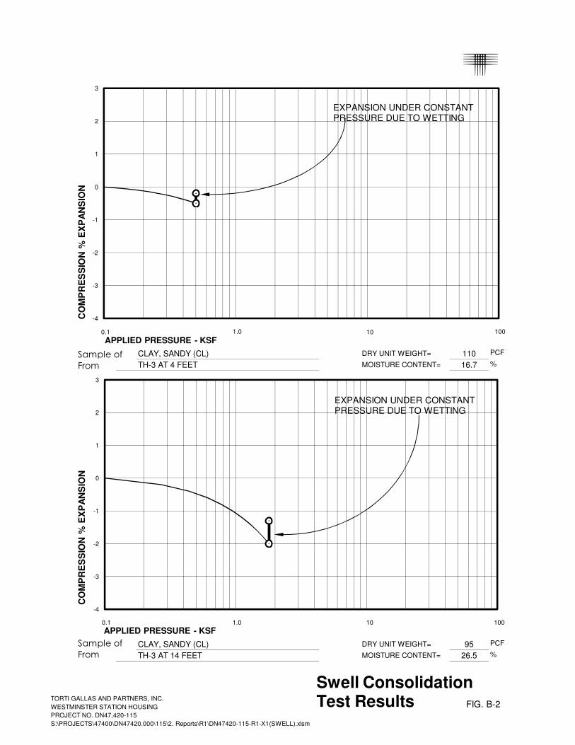
Sample of CLAY, SANDY (CL) DRY UNIT WEIGHT= 110 PCF
From TH-3 AT 4 FEET MOISTURE CONTENT= 16.7 %
Sample of CLAY, SANDY (CL) DRY UNIT WEIGHT= 95 PCF
From TH-3 AT 14 FEET MOISTURE CONTENT= 26.5 %
APPLIED PRESSURE - KSF
APPLIED PRESSURE - KSF
CO
MP
RE
SS
ION
% E
XP
AN
SIO
N
Swell Consolidation
Test Results FIG. B-2
CO
MP
RE
SS
ION
% E
XP
AN
SIO
N
-4
-3
-2
-1
0
1
2
3
EXPANSION UNDER CONSTANT
PRESSURE DUE TO WETTING
-4
-3
-2
-1
0
1
2
3
EXPANSION UNDER CONSTANT
PRESSURE DUE TO WETTING
0.1 1.0 10 100
0.1 1.0 10 100
TORTI GALLAS AND PARTNERS, INC.
WESTMINSTER STATION HOUSING
PROJECT NO. DN47,420-115
S:\PROJECTS\47400\DN47420.000\115\2. Reports\R1\DN47420-115-R1-X1(SWELL).xlsm

Sample of CLAY, SANDY (CL) DRY UNIT WEIGHT= 104 PCF
From TH-4 AT 14 FEET MOISTURE CONTENT= 17.4 %
Sample of CLAY, SANDY (CL) DRY UNIT WEIGHT= 105 PCF
From TH-5 AT 4 FEET MOISTURE CONTENT= 18.7 %
APPLIED PRESSURE - KSF
APPLIED PRESSURE - KSF
CO
MP
RE
SS
ION
% E
XP
AN
SIO
N
Swell Consolidation
Test Results FIG. B-3
CO
MP
RE
SS
ION
% E
XP
AN
SIO
N
-4
-3
-2
-1
0
1
2
3
ADDITIONAL COMPRESSION
UNDER CONSTANT PRESSURE
DUE TO WETTING
-4
-3
-2
-1
0
1
2
3
EXPANSION UNDER CONSTANT
PRESSURE DUE TO WETTING
0.1 1.0 10 100
0.1 1.0 10 100
TORTI GALLAS AND PARTNERS, INC.
WESTMINSTER STATION HOUSING
PROJECT NO. DN47,420-115
S:\PROJECTS\47400\DN47420.000\115\2. Reports\R1\DN47420-115-R1-X1(SWELL).xlsm

Sample of CLAY, SANDY (CL) DRY UNIT WEIGHT= 112 PCF
From TH-6 AT 4 FEET MOISTURE CONTENT= 16.6 %
Sample of CLAY, SANDY (CL) DRY UNIT WEIGHT= 106 PCF
From TH-7 AT 4 FEET MOISTURE CONTENT= 6.5 %
APPLIED PRESSURE - KSF
APPLIED PRESSURE - KSF
CO
MP
RE
SS
ION
% E
XP
AN
SIO
N
Swell Consolidation
Test Results FIG. B-4
CO
MP
RE
SS
ION
% E
XP
AN
SIO
N
-4
-3
-2
-1
0
1
2
3
EXPANSION UNDER CONSTANT
PRESSURE DUE TO WETTING
-4
-3
-2
-1
0
1
2
3
EXPANSION UNDER CONSTANT
PRESSURE DUE TO WETTING
0.1 1.0 10 100
0.1 1.0 10 100
TORTI GALLAS AND PARTNERS, INC.
WESTMINSTER STATION HOUSING
PROJECT NO. DN47,420-115
S:\PROJECTS\47400\DN47420.000\115\2. Reports\R1\DN47420-115-R1-X1(SWELL).xlsm

Sample of CLAY, SANDY (CL) DRY UNIT WEIGHT= 98 PCF
From TH-7 AT 9 FEET MOISTURE CONTENT= 20.7 %
Sample of CLAYSTONE DRY UNIT WEIGHT= 103 PCF
From TH-7 AT 14 FEET MOISTURE CONTENT= 21.8 %
APPLIED PRESSURE - KSF
APPLIED PRESSURE - KSF
CO
MP
RE
SS
ION
% E
XP
AN
SIO
N
Swell Consolidation
Test Results FIG. B-5
CO
MP
RE
SS
ION
% E
XP
AN
SIO
N
-4
-3
-2
-1
0
1
2
3
EXPANSION UNDER CONSTANT
PRESSURE DUE TO WETTING
-4
-3
-2
-1
0
1
2
3
EXPANSION UNDER CONSTANT
PRESSURE DUE TO WETTING
0.1 1.0 10 100
0.1 1.0 10 100
TORTI GALLAS AND PARTNERS, INC.
WESTMINSTER STATION HOUSING
PROJECT NO. DN47,420-115
S:\PROJECTS\47400\DN47420.000\115\2. Reports\R1\DN47420-115-R1-X1(SWELL).xlsm

Sample of CLAYSTONE DRY UNIT WEIGHT= 99 PCF
From TH-7 AT 19 FEET MOISTURE CONTENT= 23.4 %
APPLIED PRESSURE - KSF
CO
MP
RE
SS
ION
% E
XP
AN
SIO
N
Swell Consolidation
Test Results FIG. B-6
-8
-7
-6
-5
-4
-3
-2
-1
0
1
2
3
4
5
6
7
EXPANSION UNDER CONSTANT
PRESSURE DUE TO WETTING
0.1 1.0 10 100
TORTI GALLAS AND PARTNERS, INC.
WESTMINSTER STATION HOUSING
PROJECT NO. DN47,420-115
S:\PROJECTS\47400\DN47420.000\115\2. Reports\R1\DN47420-115-R1-X1(SWELL).xlsm

Sample of CLAYSTONE DRY UNIT WEIGHT= 103 PCF
From TH-7 AT 24 FEET MOISTURE CONTENT= 20.2 %
APPLIED PRESSURE - KSF
CO
MP
RE
SS
ION
% E
XP
AN
SIO
N
Swell Consolidation
Test Results FIG. B-7
-8
-7
-6
-5
-4
-3
-2
-1
0
1
2
3
4
5
6
7
EXPANSION UNDER CONSTANT
PRESSURE DUE TO WETTING
0.1 1.0 10 100
TORTI GALLAS AND PARTNERS, INC.
WESTMINSTER STATION HOUSING
PROJECT NO. DN47,420-115
S:\PROJECTS\47400\DN47420.000\115\2. Reports\R1\DN47420-115-R1-X1(SWELL).xlsm

Sample of CLAYSTONE DRY UNIT WEIGHT= 89 PCF
From TH-8 AT 14 FEET MOISTURE CONTENT= 27.5 %
Sample of FILL, CLAY, SANDY DRY UNIT WEIGHT= 105 PCF
From TH-10 AT 4 FEET MOISTURE CONTENT= 15.3 %
APPLIED PRESSURE - KSF
APPLIED PRESSURE - KSF
CO
MP
RE
SS
ION
% E
XP
AN
SIO
N
Swell Consolidation
Test Results FIG. B-8
CO
MP
RE
SS
ION
% E
XP
AN
SIO
N
-4
-3
-2
-1
0
1
2
3
EXPANSION UNDER CONSTANT
PRESSURE DUE TO WETTING
-4
-3
-2
-1
0
1
2
3
EXPANSION UNDER CONSTANT
PRESSURE DUE TO WETTING
0.1 1.0 10 100
0.1 1.0 10 100
TORTI GALLAS AND PARTNERS, INC.
WESTMINSTER STATION HOUSING
PROJECT NO. DN47,420-115
S:\PROJECTS\47400\DN47420.000\115\2. Reports\R1\DN47420-115-R1-X1(SWELL).xlsm

TABLE B - I
SUMMARY OF LABORATORY TEST RESULTS
SWELL TEST DATA ATTERBERG LIMITS UNCONFINED SOLUBLE PASSING
BORING DEPTH MOISTURE DRY SWELL COMPRESSION APPLIED SWELL LIQUID PLASTICITY COMPRESSIVE SULFATE NO. 200 SOIL TYPE
CONTENT DENSITY PRESSURE PRESSURE LIMIT INDEX STRENGTH CONTENT SIEVE
(ft) (%) (pcf) (%) (%) (psf) (psf) (psf) (%) (%)
TH-1 4 7.9 119 3.1 500 7,000 0.05 CLAY, SANDY (CL)
TH-1 9 7.8 111 38 SAND, CLAYEY (SC)
TH-1 19 14.7 116 5,200 CLAY, SANDY (CL)
TH-1 24 18.6 110 44 23 12,000 83 CLAYSTONE
TH-2 4 20.9 105 52 32 7,100 69 CLAY, SANDY (CL)
TH-2 9 17.5 108 0.4 1,100 CLAY, SANDY (CL)
TH-2 14 16.3 110 42 SAND, VERY CLAYEY (SC)
TH-3 4 16.7 110 0.3 500 CLAY, SANDY (CL)
TH-3 14 26.5 95 0.7 1,800 CLAY, SANDY (CL)
TH-3 19 15.4 106 49 SAND, VERY CLAYEY (SC)
TH-4 9 16.3 108 3,400 CLAY, SANDY (CL)
TH-4 14 17.4 104 0.1 1,800 CLAY, SANDY (CL)
TH-5 4 18.7 105 1.4 500 3,600 <0.01 CLAY, SANDY (CL)
TH-5 9 12.7 117 42 SAND, VERY CLAYEY (SC)
TH-5 19 7.2 104 11 SAND AND GRAVEL, SLIGHTLY SILTY (SP-SM, GP-GM)
TH-6 4 16.6 112 0.9 500 CLAY, SANDY (CL)
TH-6 14 5.4 100 11 SAND AND GRAVEL, SLIGHTLY SILTY (SP-SM, GP-GM)
TH-6 24 19.7 105 43 CLAYSTONE/SANDSTONE
TH-7 4 6.5 106 0.6 500 1,400 CLAY, SANDY (CL)
TH-7 9 20.7 98 0.6 1,100 2,000 CLAY, SANDY (CL)
TH-7 14 21.8 103 1.1 1,800 5,100 CLAYSTONE
TH-7 19 23.4 99 0.7 2,400 5,000 CLAYSTONE
TH-7 24 20.2 103 1.1 3,000 8,100 CLAYSTONE
TH-8 4 4.4 88 23 CLAYSTONE/SANDSTONE
TH-8 9 23.6 99 10,600 0.04 CLAYSTONE
TH-8 14 27.5 89 0.6 1,800 CLAYSTONE
TH-9 4 20.4 102 36 15 55 CLAY, VERY SANDY (CL)
TH-9 14 14.7 111 39 SAND, CLAYEY (SC)
TH-9 19 22.5 102 9,400 CLAYSTONE
TH-9 29 23.4 103 75 45 13,800 95 CLAYSTONE
TH-10 4 15.3 105 0.6 500 FILL, CLAY, SANDY
TH-10 14 9.4 119 11 SAND AND GRAVEL, SLIGHTLY SILTY (SP-SM, GP-GM)
TH-10 19 17.6 108 25 CLAYSTONE/SANDSTONE
TORTI GALLAS AND PARTNERS, INC.
WESTMINSTER STATION HOUSING
PROJECT NO. DN47,420-115
S:\PROJECTS\47400\DN47420.000\115\2. Reports\R1\DN47420-115-R1-X2(TABLE).xlsx PAGE 1 OF 1

TORTI GALLAS AND PARTNERS, INC. WESTMINSTER STATION HOUSING CTL | T PROJECT NO. DN47,420-115 S:\PROJECTS\47400\DN47420.000\115\2. Reports\R1\DN47420-115-R1.docx
APPENDIX C
GUIDELINE SITE GRADING SPECIFICATIONS
Adams County Housing Authority Westminster Station Housing Westminster, Colorado

TORTI GALLAS AND PARTNERS, INC. WESTMINSTER STATION HOUSING CTL | T PROJECT NO. DN47,420-115 S:\PROJECTS\47400\DN47420.000\115\2. Reports\R1\DN47420-115-R1.docx
C-1
GUIDELINE SITE GRADING SPECIFICATIONS
Adams County Housing Authority Westminster Station Housing Westminster, Colorado
1. DESCRIPTION
This item shall consist of the excavation, transportation, placement and compac-tion of materials from locations indicated on the plans, or staked by the Engineer, as necessary to achieve preliminary street and overlot grade elevations. These specifications shall also apply to compaction of excess cut materials that may be placed outside of the development boundaries.
2. GENERAL
The Soils Representative shall be the Owner's Representative. The Soils Repre-sentative shall approve fill materials, method of placement, moisture contents and percent compaction, and shall give written approval of the completed fill.
3. CLEARING JOB SITE
The Contractor shall substantially remove all debris, vegetation, organics and other deleterious materials before excavation or fill placement. The Contractor shall dispose of the cleared material to provide the Owner with a clean, neat ap-pearing job site. Cleared material shall not be placed in areas to receive fill or where the material will support structures of any kind.
4. AREA TO BE FILLED
Debris, vegetation, organics and other deleterious materials shall be substantially removed from the ground surface upon which fill is to be placed. The surface shall then be plowed or scarified until the surface is free from ruts, hummocks or other uneven features, which would prevent uniform compaction.
After the foundation for the fill has been cleared and scarified, it shall be disced or bladed until it is free from large clods, brought to the proper moisture content (optimum to 3 percent above optimum moisture content for clays and within 2 percent of optimum moisture content for sands) and compacted to at least 95 percent of maximum dry density as determined in accordance with ASTM D 698.
5. FILL MATERIALS
Fill soils shall be substantially free from debris, vegetation, organics and other deleterious materials, and shall not contain rocks or lumps having a diameter greater than six (6) inches. Claystone bedrock should be broken down to three (3) inches or smaller in size. Fill materials shall be obtained from cut areas shown on the plans or staked in the field by the Engineer.

TORTI GALLAS AND PARTNERS, INC. WESTMINSTER STATION HOUSING CTL | T PROJECT NO. DN47,420-115 S:\PROJECTS\47400\DN47420.000\115\2. Reports\R1\DN47420-115-R1.docx
C-2
On-site materials classifying as CL, CH, SC, SM, SW, SP, GP, GC and GM are acceptable.
6. MOISTURE CONTENT
Fill material classifying as CH, CL and SC shall be moisture conditioned to be-tween 0 and 3 percent above optimum moisture content. Granular soils classify-ing as SM, SW, SP, GP, GC and GM shall be moisture conditioned to within 2 percent of optimum moisture content as determined from Proctor compaction tests. Sufficient laboratory compaction tests shall be made to determine the op-timum moisture content for the various soils encountered in borrow areas.
The Contractor may be required to add moisture to the excavation materials in the borrow area if, in the opinion of the Soils Representative, it is not possible to obtain uniform moisture content by adding water on the fill surface. The Contrac-tor may be required to rake or disc the fill soils to provide uniform moisture con-tent through the soils.
The application of water to embankment materials shall be made with any type of watering equipment approved by the Soils Representative, which will give the desired results. Water jets from the spreader shall not be directed at the em-bankment with such force that fill materials are washed out.
Should too much water be added to any part of the fill, such that the material is too wet to permit the desired compaction from being obtained, rolling and all work on that section of the fill shall be delayed until the material has been allowed to dry to the required moisture content. The Contractor will be permitted to rework wet material in an approved manner to hasten its drying.
7. COMPACTION OF FILL AREAS
Selected fill material shall be placed and mixed in evenly spread layers. After each fill layer has been placed, it shall be uniformly compacted to not less than the specified percentage of maximum density. Fill shall be compacted to at least 95 percent of the maximum density as determined in accordance with ASTM D 698. At the option of the Soils Representative, soils classifying as SW, GP, GC, or GM may be compacted to 95 percent of maximum density as determined in accordance with ASTM D 1557 or 70 percent relative density for cohesionless sand soils. Fill materials shall be placed such that the thickness of loose materi-als does not exceed 10 inches and the compacted lift thickness does not exceed 6 inches.
Compaction as specified above, shall be obtained by the use of sheepsfoot roll-ers, multiple-wheel pneumatic-tired rollers, or other equipment for soils classify-ing as CL, CH, or SC. Granular fill shall be compacted using vibratory equipment or other approved equipment. Compaction shall be accomplished while the fill material is at the specified moisture content. Compaction of each layer shall be continuous over the entire area. Compaction equipment shall make sufficient trips to ensure that the required density is obtained.

TORTI GALLAS AND PARTNERS, INC. WESTMINSTER STATION HOUSING CTL | T PROJECT NO. DN47,420-115 S:\PROJECTS\47400\DN47420.000\115\2. Reports\R1\DN47420-115-R1.docx
C-3
8. COMPACTION OF SLOPES
Fill slopes shall be compacted by means of sheepsfoot rollers or other suitable equipment. Compaction operations shall be continued until slopes are stable, but not too dense for planting, and there is not appreciable amount of loose soils on the slopes. Compaction of slopes may be done progressively in increments of three to five feet (3' to 5') in height or after the fill is brought to its total height. Permanent fill slopes shall not exceed 3:1 (horizontal to vertical).
9. PLACEMENT OF FILL ON NATURAL SLOPES
Where natural slopes are steeper than 20 percent in grade and the placement of fill is required, benches shall be cut at the rate of one bench for each 5 feet in height (minimum of two benches). Benches shall be at least 10 feet in width. Larger bench widths may be required by the Engineer. Fill shall be placed on completed benches as outlined within this specification.
10. DENSITY TESTS
Field density tests shall be made by the Soils Representative at locations and depths of his choosing. Where sheepsfoot rollers are used, the soil may be dis-turbed to a depth of several inches. Density tests shall be taken in compacted material below the disturbed surface. When density tests indicate that the density or moisture content of any layer of fill or portion thereof is not within specification, the particular layer or portion shall be reworked until the required density or mois-ture content has been achieved.
11. SEASONAL LIMITS
No fill material shall be placed, spread or rolled while it is frozen, thawing, or dur-ing unfavorable weather conditions. When work is interrupted by heavy precipita-tion, fill operations shall not be resumed until the Soils Representative indicates that the moisture content and density of previously placed materials are as speci-fied.
12. NOTICE REGARDING START OF GRADING
The Contractor shall submit notification to the Soils Representative and Owner advising them of the start of grading operations at least three (3) days in advance of the starting date. Notification shall also be submitted at least 3 days in ad-vance of any resumption dates when grading operations have been stopped for any reason other than adverse weather conditions.
13. REPORTING OF FIELD DENSITY TESTS
Density tests made by the Soils Representative, as specified under "Density Tests" above, shall be submitted progressively to the Owner. Dry density, mois-ture content, and percentage compaction shall be reported for each test taken.

TORTI GALLAS AND PARTNERS, INC. WESTMINSTER STATION HOUSING CTL | T PROJECT NO. DN47,420-115 S:\PROJECTS\47400\DN47420.000\115\2. Reports\R1\DN47420-115-R1.docx
C-4
14. DECLARATION REGARDING COMPLETED FILL
The Soils Engineer shall provide a written declaration stating that the site was filled with acceptable materials, and was placed in general accordance with the specifications.
TORTI GALLAS AND PARTNERS, INC. WESTMINSTER STATION HOUSING CTL | T PROJECT NO. DN47,420-115 S:\PROJECTS\47400\DN47420.000\115\2. Reports\R1\DN47420-115-R1.docx
APPENDIX D
GUIDELINE SUB-EXCAVATION SPECIFICATIONS
Adams County Housing Authority Westminster Station Housing Westminster, Colorado
Note: This guideline is intended for use with sub-excavation. If sub-excavation is
not selected, the guidelines in Appendix C should be followed.

TORTI GALLAS AND PARTNERS, INC. D-1 WESTMINSTER STATION HOUSING CTL | T PROJECT NO. DN47,420-115 S:\PROJECTS\47400\DN47420.000\115\2. Reports\R1\DN47420-115-R1.docx
GUIDELINE SUB-EXCAVATION SPECIFICATIONS
Adams County Housing Authority Westminster Station Housing Westminster, Colorado
1. DESCRIPTION
This item shall consist of the excavation, transportation, placement and compac-tion of materials from locations indicated on the plans, or staked by the Engineer, as necessary to achieve preliminary street and overlot grade elevations. These specifications shall also apply to compaction of excess cut materials that may be placed outside of the development boundaries.
2. GENERAL
The Soils Representative shall be the Owner's Representative. The Soils Repre-sentative shall approve fill materials, method of placement, moisture contents and percent compaction, and shall give written approval of the completed fill.
3. CLEARING JOB SITE
The Contractor shall substantially remove all debris, vegetation, organics and other deleterious materials before excavation or fill placement. The Contractor shall dispose of the cleared material to provide the Owner with a clean, neat appearing job site. Cleared material shall not be placed in areas to receive fill or where the material will support structures of any kind.
4. AREA TO BE FILLED
Debris, vegetation, organics and other deleterious materials shall be substantially removed from the ground surface upon which fill is to be placed. The surface shall then be plowed or scarified until the surface is free from ruts, hummocks or other uneven features, which would prevent uniform compaction.
After the foundation for the fill has been cleared and scarified, it shall be disced or bladed until it is free from large clods, brought to the proper moisture content (between optimum moisture content and 3 percent above optimum for clay and within 2 percent of optimum moisture content for sand) and compacted to at least 95 percent of maximum dry density as determined in accordance with ASTM D 698.
5. FILL MATERIALS
Fill soils shall be substantially free from debris, vegetation, organics and other deleterious materials, and shall not contain rocks or lumps having a diameter greater than six (6) inches. Clay and claystone should be broken down to three (3) inches or smaller in size. Fill materials shall be obtained from cut areas shown on the plans or staked in the field by the Engineer.
TORTI GALLAS AND PARTNERS, INC. D-2 WESTMINSTER STATION HOUSING CTL | T PROJECT NO. DN47,420-115 S:\PROJECTS\47400\DN47420.000\115\2. Reports\R1\DN47420-115-R1.docx
On-site materials classifying as CL, CH, SC, SM, SW, SP, GP, GC and GM are acceptable. Concrete, asphalt, and other deleterious materials or debris shall not be used as fill.
6. MOISTURE CONTENT Fill materials shall be moisture-conditioned to within limits of optimum moisture content specified in “Moisture Content and Density Criteria”. Sufficient laboratory compaction tests shall be made to determine the optimum moisture content for the various soils encountered in borrow areas or imported to the site. The Contractor may be required to add moisture to the excavation materials in the borrow area if, in the opinion of the Soils Engineer, it is not possible to obtain uniform moisture content by adding water on the fill surface. The Contractor will be required to rake or disc the fill to provide uniform moisture content throughout the fill. The application of water to embankment materials shall be made with any type of watering equipment that will give the desire results. Water jets from the spreader shall not be directed at the embankment with such force that fill materials are washed out. Should too much water be added to any part of the fill, such that the material is too wet to permit the desired compaction from being obtained, rolling and all work on that section of the fill shall be delayed until the material has been allowed to dry to the required moisture content. The Contractor will be permitted to rework wet material in an approved manner to hasten its drying.
7. COMPACTION OF FILL MATERIALS Selected fill material shall be placed and mixed in evenly spread layers. After each fill layer has been placed, it shall be uniformly compacted to not less than the specified percentage of maximum density given in “Moisture Content and Density Criteria”. Fill materials shall be placed such that the thickness of loose material does not exceed 8 inches and the compacted lift thickness does not ex-ceed 6 inches. Compaction, as specified above, shall be obtained by the use of suitable equip-ment. Compaction shall be accomplished while the fill material is at the specified moisture content. Compaction of each layer shall be continuous over the entire area. Compaction equipment shall make sufficient trips to ensure that the re-quired density is obtained.
8. MOISTURE CONTENT AND DENSITY CRITERIA Fill material shall be substantially compacted to at least 95 percent of standard Proctor maximum dry density (ASTM D 698, AASHTO T 99) at 0 to 3 percent above optimum moisture content. Additional criteria for acceptance are present-ed in DENSITY TESTS.

TORTI GALLAS AND PARTNERS, INC. D-3 WESTMINSTER STATION HOUSING CTL | T PROJECT NO. DN47,420-115 S:\PROJECTS\47400\DN47420.000\115\2. Reports\R1\DN47420-115-R1.docx
9. DENSITY TESTS Field density tests shall be made by the Soils Engineer at locations and depths of his choosing. Where sheepsfoot rollers are used, the soil may be disturbed to a depth of several inches. Density tests shall be taken in compacted material below the disturbed surface. When density tests indicate the density or moisture con-tent of any layer of fill or portion thereof not within specifications, the particular layer or portion shall be reworked until the required density or moisture content has been achieved. Allowable ranges of moisture content and density given in MOISTURE CON-TENT AND DENSITY CRITERIA are based on design considerations. The mois-ture shall be controlled by the Contractor so that moisture content of the com-pacted earth fill, as determined by tests performed by the Soils Engineer, shall be within the limits given. The Soils Engineer will inform the Contractor when the placement moisture is less than or exceeds the limits specified and the Contrac-tor shall immediately make adjustments in procedures as necessary to maintain placement moisture content within the specified limits, to satisfy the following re-quirements. A. Moisture
1. The average moisture content of material tested each day shall not be less than 1 percent over optimum moisture content.
2. Material represented by samples tested having moisture lower
than optimum will be rejected. Such rejected materials shall be reworked until moisture equal to or greater than optimum is achieved.
B. Density
1. The average dry density of material tested each day shall not be less than 95 percent of standard Proctor maximum dry density (ASTM D 698).
2. No more than 10 percent of the material represented by the sam-ples tested shall be at dry densities less than 95 percent of stand-ard Proctor maximum dry density (ASTM D 698).
3. Material represented by samples tested having dry density less
than 94 percent of standard Proctor maximum dry density (ASTM D 698) will be rejected. Such rejected materials shall be reworked until a dry density equal to or greater than 95 percent of standard Proctor maximum dry density (ASTM D 698) is obtained.

TORTI GALLAS AND PARTNERS, INC. D-4 WESTMINSTER STATION HOUSING CTL | T PROJECT NO. DN47,420-115 S:\PROJECTS\47400\DN47420.000\115\2. Reports\R1\DN47420-115-R1.docx
10. OBSERVATION AND TESTING OF FILL Observation by the Soils Engineer shall be sufficient during the placement of fill and compaction operations so that they can declare the fill was placed in general conformance with specifications. All observations necessary to test the place-ment of fill and observe compaction operations will be at the expense of the Owner.
11. SEASONAL LIMITS No fill material shall be placed, spread or rolled while it is frozen, thawing, or dur-ing unfavorable weather conditions. When work is interrupted by heavy precipita-tion, fill operations shall not be resumed until the Soils Engineer indicates the moisture content and density of previously placed materials are as specified.
12. REPORTING OF FIELD DENSITY TESTS Density tests made by the Soils Engineer, as specified under “Density Tests” above, shall be submitted progressively to the Owner. Dry density, moisture con-tent and percentage compaction shall be reported for each test taken.