Preliminary engineering calculations and design ...
23
1 Preliminary engineering calculations and design assumptions for Cox’s walk footbridge alternative repair proposal, July 2020_RevB Design standards / codes used in the structural calculations; • DMRB CD 353 – Design Criteria for footbridges, Mar 2020 • BS EN 1990, Eurocode 0: Basis of structural design • BS EN 1991-2, Eurocode 1: Actions on structures. Traffic loads on bridges • BS EN 1992-1-1_2004, Eurocode 2: Design of concrete structures General rules and rules for buildings • BS EN 1993-1-1_2005, Eurocode 3: Design of steel structures General rules and rules for buildings • BS EN 1995-1-1_2004, Eurocode 5: Design of timber structures Common rules and rules for buildings • BS EN 1996-1-1_2005, Eurocode 6: Design of masonry structures General rules for reinforced and unreinforced masonry structures Introduction; This is a preliminary calculation report for the alternative repair proposal for the Cox’s walk footbridge. This report includes calculations for the splice connection proposed to extend the approx. 9.1m span 305UC to a 10.8m span 305UC, and an associated check of the natural frequency of the beam and a historic steelwork stress check of the beam. A calculation is presented justifying the 80mm THK RC slab required to eliminate any increase in dead load on the central (West) pier, including a check under a 10kN point load as per BS EN 1991-2_2003. Tekla Structural Designer 2019i has been used for the structural analysis and to determine the approx. max. screw pile loads (62kN) which is given in unfactored (SLS) format in the notes on drawing 001, which is believed to be within the capacity of a screw pile installed in such circumstances although this would need to be confirmed with a piling contractor in relation to site investigation. The SLS pile loads could be further refined at the following stage of design. For the purposes of discussions with screw pile contractors, if the contractor’s design is governed by settlement it should be noted that the 62kN SLS load given includes the full 5kN/m 2 imposed load without any ‘quasi-permanent’ load reduction which would typically be associated with assessing serviceability in relation to long-term settlement. Live Loading; The design live load has been determined as per BS EN 1991-2_2003, Clause 5.3.2.1 – Uniformly distributed load. A live load of 5.0 kN/m 2 (considering continuous, dense crowding) has been used in the analysis and design. This could be reduced to 4.0 kN/m 2 (in accordance with 5.3.2.1 (2) (5.1) at the client’s request if continuous, dense crowding is not required due to the nature and setting of this footbridge.
Transcript of Preliminary engineering calculations and design ...

1
Preliminary engineering calculations and design assumptions for Cox’s walk footbridge
alternative repair proposal, July 2020_RevB
Design standards / codes used in the structural calculations;
• DMRB CD 353 – Design Criteria for footbridges, Mar 2020
• BS EN 1990, Eurocode 0: Basis of structural design
• BS EN 1991-2, Eurocode 1: Actions on structures. Traffic loads on bridges
• BS EN 1992-1-1_2004, Eurocode 2: Design of concrete structures General rules and rules for
buildings
• BS EN 1993-1-1_2005, Eurocode 3: Design of steel structures General rules and rules for buildings
• BS EN 1995-1-1_2004, Eurocode 5: Design of timber structures Common rules and rules for
buildings
• BS EN 1996-1-1_2005, Eurocode 6: Design of masonry structures General rules for reinforced and
unreinforced masonry structures
Introduction;
This is a preliminary calculation report for the alternative repair proposal for the Cox’s walk footbridge. This
report includes calculations for the splice connection proposed to extend the approx. 9.1m span 305UC to a
10.8m span 305UC, and an associated check of the natural frequency of the beam and a historic steelwork
stress check of the beam. A calculation is presented justifying the 80mm THK RC slab required to eliminate
any increase in dead load on the central (West) pier, including a check under a 10kN point load as per BS EN
1991-2_2003.
Tekla Structural Designer 2019i has been used for the structural analysis and to determine the approx. max.
screw pile loads (62kN) which is given in unfactored (SLS) format in the notes on drawing 001, which is
believed to be within the capacity of a screw pile installed in such circumstances although this would need
to be confirmed with a piling contractor in relation to site investigation. The SLS pile loads could be further
refined at the following stage of design.
For the purposes of discussions with screw pile contractors, if the contractor’s design is governed by
settlement it should be noted that the 62kN SLS load given includes the full 5kN/m2 imposed load without
any ‘quasi-permanent’ load reduction which would typically be associated with assessing serviceability in
relation to long-term settlement.
Live Loading;
The design live load has been determined as per BS EN 1991-2_2003, Clause 5.3.2.1 – Uniformly distributed
load. A live load of 5.0 kN/m2 (considering continuous, dense crowding) has been used in the analysis and
design. This could be reduced to 4.0 kN/m2 (in accordance with 5.3.2.1 (2) (5.1) at the client’s request if
continuous, dense crowding is not required due to the nature and setting of this footbridge.

2
A new Reinforced Concrete Deck Slab of 80mm thickness is proposed over the new 10.8m span 305x137 UC
beams to remove any increase in dead load on the left central masonry pier due. The analysis below has
been carried out taking into account the stiffness of the steel beams and is for the load combination
(1.35Gk + 1.5Qk). It can be seen that the slab generally requires very little reinforcement due to the very
small spans of the slab (900mm between flanges of steel beam), and so nominal reinforcement of A193
mesh is adequate. The point load requirement of BS EN 1991-2 has also been met.
Reinforcement required in 80mm THK RC slab (35mm cover top – 30mm cover bottom) RC32/40
concrete, fixing tolerance 5mm.
X top
X bottom
Y top
Y bottom

3
10kN Point Load in accordance with NA to BS EN 1991-2:2003;
A193 or B196 mesh fine by inspection, 5mm bars at 100C-C laid parallel to the steel beams, 7mm
bars at 200C-C laid across the steel beams.

4
Increase in load calculation on Central (West) Pier due to extending beam
Existing Reactions on left pier from existing bridge
Dead load
Live load

5
Proposed Reactions on left pier from proposed bridge (load-sharing with truss not assumed)
Dead load
Live load
Change in load on left pier;
Dead load
Proposed Load / Existing Load
= 17+21.6+17+16.6+21.2+16.5 / 17+21.6+17+16.6+21.2+16.5 = 110kN / 110kN = no change in load
Live load
= 23.2+19.1+33.5+27.5+23+19 / 19.6+19.1+28+27.5+19.5+19 = 145kN / 133kN = 12kN or 9%
increase in load ( < 10%).

6
Proposed existing steel beam (10.8m span) design check (1950s steelwork allowable stress
approach – lateral restraint provided by deck and tie beams)
Allowable stress = 230 / 1.3 = 177 N/mm2
ULS Bending Moment = 185kNm
305x305x118 UC;
Zyy = 1760 x 103 Nmm3
Stress = 185 * 10^6 / 1760 x 10^3 = 105 N/mm2
Utilisation = 105 / 177 = 0.59
305x305x97 UC Stress = 185 * 10^6 / 1450 x 10^3 = 128 N/mm2
Utilisation = 128 / 177 = 0.72
Beam deflection check deflection = 23.2mm = L/470 < L/250 therefore okay;
Natural Frequency check
Vibration analysis has been carried out for 2 beam sizes, 305x305x137 UC which it is suspected is
the actual size of beam, and 305x305x118 UC to account for effects of a nominal amount of
corrosion.
The load case used considers 100% dead load and 100% live load considering 4 No. 100kg people
running across the bridge closely spaced and at mid-span of the bridge.
305x305x137 UC - Frequency of 10.8m span = 5.5Hz > 3Hz therefore okay;

7
305x305x118 UC - Frequency of 10.8m span = 5.2Hz > 3Hz therefore okay;
Proposed splice detail; (305x305x97 UC assumed as beam showing minor corrosion and to allow
for long lifespan of detail – 6.3mm section loss of flange and 3.9mm section loss of web – 0.3
Utilisation)
Autodesk Robot Structural Analysis Professional 2019
Calculation of the beam-to-beam splice connection
EN 1993-1-8:2005/AC:2009
Ratio
0.30

8
GENERAL
Connection no.: 6
Connection name: West 305x305x138 Splice
RIGHT BEAM
Section: UC 305x305x97
hb1 = 308 [mm] Height of beam section
bfb1 = 305 [mm] Width of beam section
twb1 = 10 [mm] Thickness of the web of beam section
tfb1 = 15 [mm] Thickness of the flange of beam section
rb1 = 15 [mm] Radius of beam section fillet
Ab1 = 12300 [mm2] Cross-sectional area of a beam
Iyb1 = 222500000 [mm4] Moment of inertia of the beam section
Material: S275
fyb1 = 275.00 [MPa] Resistance
fub1 = 430.00 [MPa]
LEFT BEAM
Section: UC 305x305x97
hb2 = 308 [mm] Height of beam section
bfb2 = 305 [mm] Width of beam section
twb2 = 10 [mm] Thickness of the web of beam section
tfb2 = 15 [mm] Thickness of the flange of beam section
rb2 = 15 [mm] Radius of beam section fillet
Ab2 = 12300 [mm2] Cross-sectional area of a beam
Iyb2 = 222500000 [mm4] Moment of inertia of the beam section
Material: S275
fyb2 = 275.00 [MPa] Resistance
fub2 = 430.00 [MPa]

9
SPLICE PLATE
Type: unilateral
lpw = 450 [mm] Plate length
hpw = 200 [mm] Plate height
tpw = 20 [mm] Plate thickness
Material: S355
fypw = 355.00 [MPa] Design resistance
fupw = 490.00 [MPa] Tensile resistance
UPPER EXTERNAL PLATE
lpe = 600 [mm] Plate length
hpe = 308 [mm] Plate height
tpe = 15 [mm] Plate thickness
Material: S355
fype = 355.00 [MPa] Design resistance
fupe = 490.00 [MPa] Tensile resistance
LOWER EXTERNAL PLATE
lpe = 600 [mm] Plate length
hpe = 308 [mm] Plate height
tpe = 15 [mm] Plate thickness
Material: S355
fype = 355.00 [MPa] Design resistance
fupe = 490.00 [MPa] Tensile resistance
RIGHT SIDE
BOLTS CONNECTING A SPLICE PLATE WITH THE BEAM WEB
The shear plane passes through the UNTHREADED portion of the bolt.
Connection category A
Class = 8.8 Bolt class
d = 24 [mm] Bolt diameter
d0 = 26 [mm] Bolt opening diameter
As = 353 [mm2] Effective section area of a bolt
Av = 452 [mm2] Area of bolt section
fyb = 640.00 [MPa] Yield strength of bolt
fub = 800.00 [MPa] Bolt tensile resistance
nh = 2 Number of bolt columns
nv = 2 Number of bolt rows
10
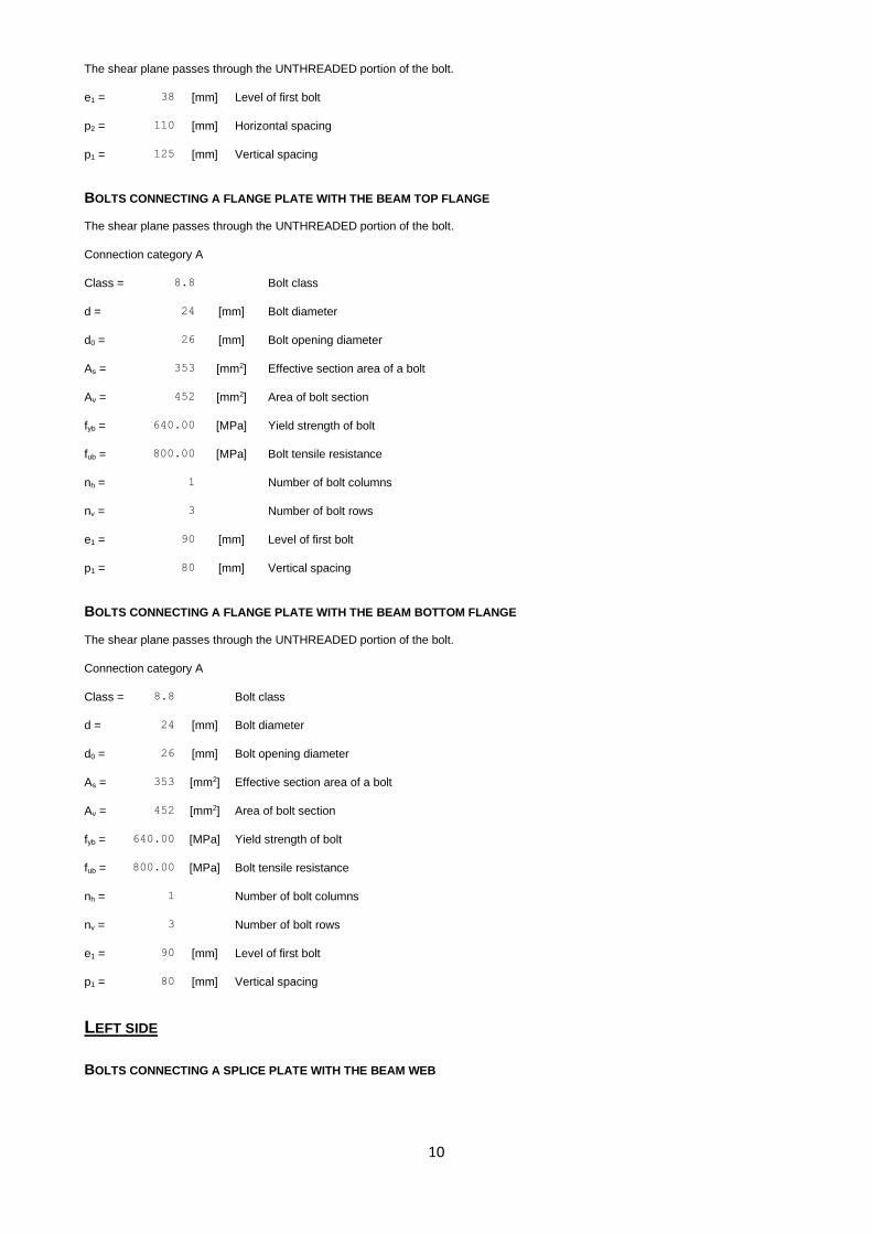
The shear plane passes through the UNTHREADED portion of the bolt.
e1 = 38 [mm] Level of first bolt
p2 = 110 [mm] Horizontal spacing
p1 = 125 [mm] Vertical spacing
BOLTS CONNECTING A FLANGE PLATE WITH THE BEAM TOP FLANGE
The shear plane passes through the UNTHREADED portion of the bolt.
Connection category A
Class = 8.8 Bolt class
d = 24 [mm] Bolt diameter
d0 = 26 [mm] Bolt opening diameter
As = 353 [mm2] Effective section area of a bolt
Av = 452 [mm2] Area of bolt section
fyb = 640.00 [MPa] Yield strength of bolt
fub = 800.00 [MPa] Bolt tensile resistance
nh = 1 Number of bolt columns
nv = 3 Number of bolt rows
e1 = 90 [mm] Level of first bolt
p1 = 80 [mm] Vertical spacing
BOLTS CONNECTING A FLANGE PLATE WITH THE BEAM BOTTOM FLANGE
The shear plane passes through the UNTHREADED portion of the bolt.
Connection category A
Class = 8.8 Bolt class
d = 24 [mm] Bolt diameter
d0 = 26 [mm] Bolt opening diameter
As = 353 [mm2] Effective section area of a bolt
Av = 452 [mm2] Area of bolt section
fyb = 640.00 [MPa] Yield strength of bolt
fub = 800.00 [MPa] Bolt tensile resistance
nh = 1 Number of bolt columns
nv = 3 Number of bolt rows
e1 = 90 [mm] Level of first bolt
p1 = 80 [mm] Vertical spacing
LEFT SIDE
BOLTS CONNECTING A SPLICE PLATE WITH THE BEAM WEB

11
The shear plane passes through the UNTHREADED portion of the bolt.
Connection category A
Class = 8.8 Bolt class
d = 24 [mm] Bolt diameter
d0 = 26 [mm] Bolt opening diameter
As = 353 [mm2] Effective section area of a bolt
Av = 452 [mm2] Area of bolt section
fyb = 640.00 [MPa] Yield strength of bolt
fub = 800.00 [MPa] Bolt tensile resistance
nh = 2 Number of bolt columns
nv = 2 Number of bolt rows
e1 = 38 [mm] Level of first bolt
p2 = 110 [mm] Horizontal spacing
p1 = 125 [mm] Vertical spacing
BOLTS CONNECTING A FLANGE PLATE WITH THE BEAM TOP FLANGE
The shear plane passes through the UNTHREADED portion of the bolt.
Connection category A
Class = 8.8 Bolt class
d = 24 [mm] Bolt diameter
d0 = 26 [mm] Bolt opening diameter
As = 353 [mm2] Effective section area of a bolt
Av = 452 [mm2] Area of bolt section
fyb = 640.00 [MPa] Yield strength of bolt
fub = 800.00 [MPa] Bolt tensile resistance
nh = 1 Number of bolt columns
nv = 3 Number of bolt rows
e1 = 90 [mm] Level of first bolt
p1 = 80 [mm] Vertical spacing
BOLTS CONNECTING A FLANGE PLATE WITH THE BEAM BOTTOM FLANGE
The shear plane passes through the UNTHREADED portion of the bolt.
Connection category A
Class = 8.8 Bolt class
d = 24 [mm] Bolt diameter
d0 = 26 [mm] Bolt opening diameter
As = 353 [mm2] Effective section area of a bolt
Av = 452 [mm2] Area of bolt section

12
The shear plane passes through the UNTHREADED portion of the bolt.
fyb = 640.00 [MPa] Yield strength of bolt
fub = 800.00 [MPa] Bolt tensile resistance
nh = 1 Number of bolt columns
nv = 3 Number of bolt rows
e1 = 90 [mm] Level of first bolt
p1 = 80 [mm] Vertical spacing
MATERIAL FACTORS
M0 = 1.00 Partial safety factor [2.2]
M2 = 1.25 Partial safety factor [2.2]
LOADS
Case: Manual calculations.
ULTIMATE LIMIT STATE
NEd1 = 5.00 [kN] Axial force
Vz,Ed1 = 47.00 [kN] Shear force
My,Ed1 = 100.00 [kN*m] Bending moment
NEd2 = 0.00 [kN] Axial force
Vz,Ed2 = 0.00 [kN] Shear force
My,Ed2 = 0.00 [kN*m] Bending moment
RESULTS
RIGHT SIDE
Axial force
Plate Ai [mm2] EQUIVALENT FORCES
Ni [kN]
EQUIVALENT FORCES
Ni(My,Ed) [kN]
Resultant force
NEd,i [kN]
Apw= 4000 1.51 - NEd,pw= 1.51
Apfue= 4620 1.74 293.46 NEd,pfue= 295.20
Apfle= 4620 1.74 -293.46 NEd,pfle= -291.71
Ni=(NEd*Ai)/(Awp+Apfue+Apfle)
NEd,i = Ni+Ni(My,Ed)
Shear force Z
Plate Ai [mm2] VzEd,i [kN]
Az,pw= 4000 Vz,Ed,pw= 47.00

13
Bending moment Y
Plate Iy,i [mm4] EQUIVALENT FORCES
My,i [kN*m]
Resultant force
My,Ed,i [kN*m]
Iy,pw= 13333333 5.24 My,Ed,pw= 5.24
Iy,pfue= 120512019 47.38 -
Iy,pfle= 120512019 47.38 -
My,i=(My,Ed*Iy,i)/(Ipw+Ipfue+Ipfle)
BOLTS CONNECTING A SPLICE PLATE WITH THE BEAM WEB
BOLT CAPACITIES
Fv,Rd = 173.72 [kN] Shear bolt resistance in the unthreaded portion of a bolt Fv,Rd= 0.6*fub*Av*m/M2
Bolt bearing on the beam
Direction x
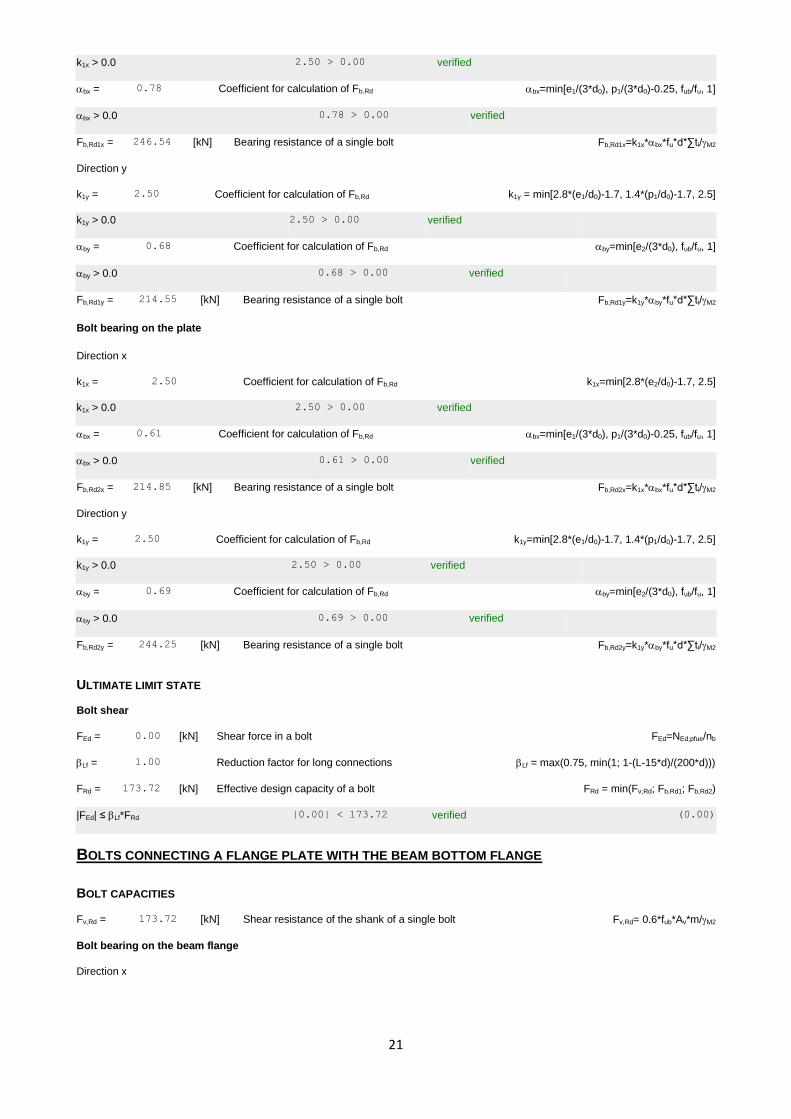
k1x = 2.50 Coefficient for calculation of Fb,Rd k1x = min[2.8*(e1/d0)-1.7, 1.4*(p1/d0)-1.7, 2.5]
k1x > 0.0 2.50 > 0.00 verified
bx = 0.80 Coefficient for calculation of Fb,Rd bx=min[e2/(3*d0), p2/(3*d0)-0.25, fub/fu, 1]
bx > 0.0 0.80 > 0.00 verified
Fb,Rd1x = 163.73 [kN] Bearing resistance of a single bolt Fb,Rd1x=k1x*bx*fu*d*∑ti/M2
Direction z
k1z = 2.50 Coefficient for calculation of Fb,Rd k1z=min[2.8*(e2/d0)-1.7, 1.4*(p2/d0)-1.7, 2.5]
k1z > 0.0 2.50 > 0.00 verified
bz = 1.00 Coefficient for calculation of Fb,Rd bz=min[e1/(3*d0), p1/(3*d0)-0.25, fub/fu, 1]
bz > 0.0 1.00 > 0.00 verified
Fb,Rd1z = 204.34 [kN] Bearing resistance of a single bolt Fb,Rd1z=k1z*bz*fu*d*∑ti/M2
Bolt bearing on the plate
Direction x
k1x = 2.34 Coefficient for calculation of Fb,Rd k1x=min[2.8*(e1/d0)-1.7, 1.4*(p1/d0)-1.7, 2.5]
k1x > 0.0 2.34 > 0.00 verified
bx = 0.64 Coefficient for calculation of Fb,Rd bx=min[e2/(3*d0), p2/(3*d0)-0.25, fub/fu, 1]
bx > 0.0 0.64 > 0.00 verified
Fb,Rd2x = 282.05 [kN] Bearing resistance of a single bolt Fb,Rd2x=k1x*bx*fu*d*∑ti/M2
Direction z
k1z = 2.50 Coefficient for calculation of Fb,Rd k1z=min[2.8*(e2/d0)-1.7, 1.4*(p2/d0)-1.7, 2.5]
k1z > 0.0 2.50 > 0.00 verified

14
bz = 0.48 Coefficient for calculation of Fb,Rd bz=min[e1/(3*d0), p1/(3*d0)-0.25, fub/fu, 1]
bz > 0.0 0.48 > 0.00 verified
Fb,Rd2z = 226.15 [kN] Bearing resistance of a single bolt Fb,Rd2z=k1z*bz*fu*d*∑ti/M2
ULTIMATE LIMIT STATE
Bolt shear
e0 = 120 [mm] Shear force eccentricity relative to the center of gravity of a bolt group e0 = e2b+0.5*(s1+(c-1)*p2)
My = 10.88 [kN*m
] Real bending moment My=My,Ed,pw+Vz,Ed,pw*e0
Fx,N = 0.38 [kN] Component force in a bolt due to influence of the longitudinal force on the x direction Fx,N=|NEd,pw|/nb
Fz,Vz = 11.75 [kN] Component force in a bolt due to influence of the shear force Vz on the z direction Fz,Vz=|Vz,Ed,pw|/nb
Fx,My
= 24.53 [kN] Component force in a bolt due to influence of the moment My on the x direction Fx,My=|My|*zi/∑(xi
2+zi2)
Fz,My
= 21.59 [kN] Component force in a bolt due to influence of the moment My on the z direction Fz,My=|My|*xi/∑(xi
2+zi2)
Fx,Ed
= 24.91 [kN] Design total force in a bolt on the direction x Fx,Ed = Fx,N+Fx,My
Fz,Ed
= 33.34 [kN] Design total force in a bolt on the direction z Fz,Ed = Fz,Vz+Fz,My
FEd = 41.62 [kN] Resultant shear force in a bolt FEd = ( Fx,Ed2 + Fz,Ed
2 )
FRd,x
=
163.7
3 [kN] Effective design capacity of a bolt on the direction x FRdx=min(FbRd1,x, FbRd2,x)
FRd,z
=
204.3
4 [kN] Effective design capacity of a bolt on the direction z FRdz=min(FbRd1,z, FbRd2,z)
|Fx,Ed| ≤ FRd,x |24.91| < 163.73 verifie
d
(0.15
)
|Fz,Ed| ≤ FRd,z |33.34| < 204.34 verifie
d
(0.16
)
FEd ≤ Fv,Rd 41.62 < 173.72 verifie
d
(0.24
)
BOLTS CONNECTING A FLANGE PLATE WITH THE BEAM TOP FLANGE
BOLT CAPACITIES
Fv,Rd = 173.72 [kN] Shear resistance of the shank of a single bolt Fv,Rd= 0.6*fub*Av*m/M2
Bolt bearing on the beam flange
Direction x
k1x = 2.50 Coefficient for calculation of Fb,Rd k1x=min[2.8*(e2/d0)-1.7, 2.5]
k1x > 0.0 2.50 > 0.00 verified
bx = 0.78 Coefficient for calculation of Fb,Rd bx=min[e1/(3*d0), p1/(3*d0)-0.25, fub/fu, 1]
bx > 0.0 0.78 > 0.00 verified
Fb,Rd1x = 246.54 [kN] Bearing resistance of a single bolt Fb,Rd1x=k1x*bx*fu*d*∑ti/M2

15
Direction y
k1y = 2.50 Coefficient for calculation of Fb,Rd k1y = min[2.8*(e1/d0)-1.7, 1.4*(p1/d0)-1.7, 2.5]
k1y > 0.0 2.50 > 0.00 verified
by = 0.68 Coefficient for calculation of Fb,Rd by=min[e2/(3*d0), fub/fu, 1]
by > 0.0 0.68 > 0.00 verified
Fb,Rd1y = 214.55 [kN] Bearing resistance of a single bolt Fb,Rd1y=k1y*by*fu*d*∑ti/M2
Bolt bearing on the plate
Direction x
k1x = 2.50 Coefficient for calculation of Fb,Rd k1x=min[2.8*(e2/d0)-1.7, 2.5]
k1x > 0.0 2.50 > 0.00 verified
bx = 0.61 Coefficient for calculation of Fb,Rd bx=min[e1/(3*d0), p1/(3*d0)-0.25, fub/fu, 1]
bx > 0.0 0.61 > 0.00 verified
Fb,Rd2x = 214.85 [kN] Bearing resistance of a single bolt Fb,Rd2x=k1x*bx*fu*d*∑ti/M2
Direction y
k1y = 2.50 Coefficient for calculation of Fb,Rd k1y=min[2.8*(e1/d0)-1.7, 1.4*(p1/d0)-1.7, 2.5]
k1y > 0.0 2.50 > 0.00 verified
by = 0.69 Coefficient for calculation of Fb,Rd by=min[e2/(3*d0), fub/fu, 1]
by > 0.0 0.69 > 0.00 verified
Fb,Rd2y = 244.25 [kN] Bearing resistance of a single bolt Fb,Rd2y=k1y*by*fu*d*∑ti/M2
ULTIMATE LIMIT STATE
Bolt shear
FEd = 51.58 [kN] Shear force in a bolt FEd=NEd,pfue/nb
Lf = 1.00 Reduction factor for long connections Lf = max(0.75, min(1; 1-(L-15*d)/(200*d)))
FRd = 173.72 [kN] Effective design capacity of a bolt FRd = min(Fv,Rd; Fb,Rd1; Fb,Rd2)
|FEd| ≤ Lf*FRd |51.58| < 173.72 verified (0.30)
BOLTS CONNECTING A FLANGE PLATE WITH THE BEAM BOTTOM FLANGE
BOLT CAPACITIES
Fv,Rd = 173.72 [kN] Shear resistance of the shank of a single bolt Fv,Rd= 0.6*fub*Av*m/M2
Bolt bearing on the beam flange
Direction x
k1x = 2.50 Coefficient for calculation of Fb,Rd k1x=min[2.8*(e2/d0)-1.7, 2.5]
k1x > 0.0 2.50 > 0.00 verified
bx = 0.78 Coefficient for calculation of Fb,Rd bx=min[e1/(3*d0), p1/(3*d0)-0.25, fub/fu, 1]
bx > 0.0 0.78 > 0.00 verified
Fb,Rd1x = 246.54 [kN] Bearing resistance of a single bolt Fb,Rd1x=k1x*bx*fu*d*∑ti/M2

16
Direction y
k1y = 2.50 Coefficient for calculation of Fb,Rd k1y = min[2.8*(e1/d0)-1.7, 1.4*(p1/d0)-1.7, 2.5]
k1y > 0.0 2.50 > 0.00 verified
by = 0.68 Coefficient for calculation of Fb,Rd by=min[e2/(3*d0), fub/fu, 1]
by > 0.0 0.68 > 0.00 verified
Fb,Rd1y = 214.55 [kN] Bearing resistance of a single bolt Fb,Rd1y=k1y*by*fu*d*∑ti/M2
Bolt bearing on the plate
Direction x
k1x = 2.50 Coefficient for calculation of Fb,Rd k1x=min[2.8*(e2/d0)-1.7, 2.5]
k1x > 0.0 2.50 > 0.00 verified
bx = 0.61 Coefficient for calculation of Fb,Rd bx=min[e1/(3*d0), p1/(3*d0)-0.25, fub/fu, 1]
bx > 0.0 0.61 > 0.00 verified
Fb,Rd2x = 214.85 [kN] Bearing resistance of a single bolt Fb,Rd2x=k1x*bx*fu*d*∑ti/M2
Direction y
k1y = 2.50 Coefficient for calculation of Fb,Rd k1y=min[2.8*(e1/d0)-1.7, 1.4*(p1/d0)-1.7, 2.5]
k1y > 0.0 2.50 > 0.00 verified
by = 0.69 Coefficient for calculation of Fb,Rd by=min[e2/(3*d0), fub/fu, 1]
by > 0.0 0.69 > 0.00 verified
Fb,Rd2y = 244.25 [kN] Bearing resistance of a single bolt Fb,Rd2y=k1y*by*fu*d*∑ti/M2
ULTIMATE LIMIT STATE
Bolt shear
FEd = -51.00 [kN] Shear force in a bolt FEd=NEd,pfle/nb
Lf = 1.00 Reduction factor for long connections Lf = max(0.75, min(1; 1-(L-15*d)/(200*d)))
FRd = 173.72 [kN] Effective design capacity of a bolt FRd = min(Fv,Rd; Fb,Rd1; Fb,Rd2)
|FEd| ≤ Lf*FRd |-51.00| < 173.72 verified (0.29)
VERIFICATION OF THE SECTION DUE TO BLOCK TEARING - [3.10]
BEAM
Nr Model Anv [mm2] Ant [mm2] V0 [kN] Veff,Rd [kN] |V0|/Veff,Rd Status
1
1757 1322 47.00 (*1) 506.25 (*) 0.09 verified
2
1322 6768 1.51 (*2) 2537.88 (**) 0.00 verified
3
1322 6768 1.51 (*2) 2537.88 (**) 0.00 verified
4
2643 980 1.51 (*2) 756.83 (**) 0.00 verified

17
Nr Model Anv [mm2] Ant [mm2] V0 [kN] Veff,Rd [kN] |V0|/Veff,Rd Status
5
2849 611 309.50 (*3) 1324.78 (***) 0.23 verified
(*1) V0 = VzEd1
(*2) V0 = NwEd
(*3) V0 = NfuEd
(*) VeffRd = 0.5*fu*Ant/M2 + (1/3)*fy*Anv/M0
(**) VeffRd = fu*Ant/M2 + (1/3)*fy*Anv/M0
(***) VeffRd = 2*[fu*Ant/M2 + (1/3)*fy*Anv/M0]
SPLICE PLATE
Nr Model Anv [mm2] Ant [mm2] V0 [kN] Veff,Rd [kN] |V0|/Veff,Rd Status
1
2470 2420 47.00 (*1) 980.57 (*) 0.05 verified
2
2420 2470 1.51 (*2) 1464.24 (**) 0.00 verified
3
2420 2470 1.51 (*2) 1464.24 (**) 0.00 verified
4
4840 1980 1.51 (*2) 1768.16 (**) 0.00 verified
(*1) V0 = 0.5*VzEd1
(*2) V0 = 0.5*NwEd
(*) VeffRd = 0.5*fu*Ant/M2 + (1/3)*fy*Anv/M0
(**) VeffRd = fu*Ant/M2 + (1/3)*fy*Anv/M0
UPPER EXTERNAL PLATE
Nr Model Anv [mm2] Ant [mm2] V0 [kN] Veff,Rd [kN] |V0|/Veff,Rd Status
1
2138 3225 295.20 (*1) 1702.30 (**) 0.17 verified
2
4275 2610 295.20 (*1) 1899.32 (**) 0.16 verified
(*1) V0 = NfueEd
(**) VeffRd = fu*Ant/M2 + (1/3)*fy*Anv/M0
VERIFICATION OF SECTIONS WEAKENED BY OPENINGS - [5.4]
BEAM
At = 6181 [mm2] Area of tension zone of the gross section
At,net = 5123 [mm2] Net area of the section in tension
0.9*(At,net/At) ≥ (fy*M2)/(fu*M0) 0.75 < 0.80
W = 1445274 [mm3] Elastic section modulus
Wnet = 1445274 [mm3] Elastic section modulus

18
W = 1445274 [mm3] Elastic section modulus
Mc,Rdnet = 397.45 [kN*m] Design resistance of the section for bending Mc,Rdnet = Wnet*fyp/M0
|M0| ≤ Mc,Rdnet |100.00| < 397.45 verified (0.25)
Av = 3048 [mm2] Effective section area for shear Av = hp*tp
Av,net = 2533 [mm2] Net area of a section effective for shear Avnet=Av-nv*d0*tp
Vpl,Rd = 483.97 [kN] Design plastic resistance for shear Vpl,Rd=(Av*fyp)/(3*M0)
|V0| ≤ Vpl,Rd |47.00| < 483.97 verified (0.10)
SPLICE PLATE
At = 2009 [mm2] Area of tension zone of the gross section
At,net = 1489 [mm2] Net area of the section in tension
0.9*(At,net/At) ≥ (fy*M2)/(fu*M0) 0.67 < 0.91
W = 133333 [mm3] Elastic section modulus
Wnet = 120992 [mm3] Elastic section modulus
Mc,Rdnet = 42.95 [kN*m] Design resistance of the section for bending Mc,Rdnet = Wnet*fyp/M0
|M0| ≤ Mc,Rdnet |10.88| < 42.95 verified (0.25)
Av = 4000 [mm2] Effective section area for shear Av = hp*tp
Av,net = 2960 [mm2] Net area of a section effective for shear Avnet=Av-nv*d0*tp
Vpl,Rd = 819.84 [kN] Design plastic resistance for shear Vpl,Rd=(Av*fyp)/(3*M0)
|V0| ≤ Vpl,Rd |47.00| < 819.84 verified (0.06)
UPPER EXTERNAL PLATE
A = 4620 [mm2] Area of tension zone of the gross section A=hpi*tpi
Anet = 3840 [mm2] Net cross-sectional area Anet=A-nv*d0*tpi
Npl,Rd = 1640.10 [kN] Design plastic resistance of the gross section Npl,Rd=A*fy/M0
Nu,Rd = 1354.75 [kN] Design ultimate resistance to normal force of the net section Nu,Rd=0.9*Anet*fu/M2
FEd = 295.20 [kN] FEd = NEd,pfue
|FEd| ≤ Nu,Rd |295.20| < 1354.75 verified (0.22)
|FEd| ≤ Npl,Rd |295.20| < 1640.10 verified (0.18)
LOWER EXTERNAL PLATE
A = 4620 [mm2] Area of tension zone of the gross section A=hpi*tpi
Anet = 3840 [mm2] Net cross-sectional area Anet=A-nv*d0*tpi
Npl,Rd = 1640.10 [kN] Design plastic resistance of the gross section Npl,Rd=A*fy/M0
Nu,Rd = 1354.75 [kN] Design ultimate resistance to normal force of the net section Nu,Rd=0.9*Anet*fu/M2
FEd = -291.71 [kN] FEd = NEd,pfli
|FEd| ≤ Nu,Rd |-291.71| < 1354.75 verified (0.22)
|FEd| ≤ Npl,Rd |-291.71| < 1640.10 verified (0.18)

19
|FEd| ≤ Nu,Rd |-291.71| < 1354.75 verified (0.22)
LEFT SIDE
Axial force
Plate Ai [mm2] EQUIVALENT FORCES
Ni [kN]
EQUIVALENT FORCES
Ni(My,Ed) [kN]
Resultant force
NEd,i [kN]
Apw= 4000 0.00 - NEd,pw= 0.00
Apfue= 4620 0.00 0.00 NEd,pfue= 0.00
Apfle= 4620 0.00 0.00 NEd,pfle= 0.00
Ni=(NEd*Ai)/(Awp+Apfue+Apfle)
NEd,i = Ni+Ni(My,Ed)
Shear force Z
Plate Ai [mm2] VzEd,i [kN]
Az,pw= 4000 Vz,Ed,pw= 0.00
Bending moment Y
Plate Iy,i [mm4] EQUIVALENT FORCES
My,i [kN*m]
Resultant force
My,Ed,i [kN*m]
Iy,pw= 13333333 0.00 My,Ed,pw= 0.00
Iy,pfue= 120512019 0.00 -
Iy,pfle= 120512019 0.00 -
My,i=(My,Ed*Iy,i)/(Ipw+Ipfue+Ipfle)
BOLTS CONNECTING A SPLICE PLATE WITH THE BEAM WEB
BOLT CAPACITIES
Fv,Rd = 173.72 [kN] Shear bolt resistance in the unthreaded portion of a bolt Fv,Rd= 0.6*fub*Av*m/M2
Bolt bearing on the beam
Direction x
k1x = 2.50 Coefficient for calculation of Fb,Rd k1x = min[2.8*(e1/d0)-1.7, 1.4*(p1/d0)-1.7, 2.5]
k1x > 0.0 2.50 > 0.00 verified
bx = 0.80 Coefficient for calculation of Fb,Rd bx=min[e2/(3*d0), p2/(3*d0)-0.25, fub/fu, 1]
bx > 0.0 0.80 > 0.00 verified
Fb,Rd1x = 163.73 [kN] Bearing resistance of a single bolt Fb,Rd1x=k1x*bx*fu*d*∑ti/M2

20
Direction z
k1z = 2.50 Coefficient for calculation of Fb,Rd k1z=min[2.8*(e2/d0)-1.7, 1.4*(p2/d0)-1.7, 2.5]
k1z > 0.0 2.50 > 0.00 verified
bz = 1.00 Coefficient for calculation of Fb,Rd bz=min[e1/(3*d0), p1/(3*d0)-0.25, fub/fu, 1]
bz > 0.0 1.00 > 0.00 verified
Fb,Rd1z = 204.34 [kN] Bearing resistance of a single bolt Fb,Rd1z=k1z*bz*fu*d*∑ti/M2
Bolt bearing on the plate
Direction x
k1x = 2.34 Coefficient for calculation of Fb,Rd k1x=min[2.8*(e1/d0)-1.7, 1.4*(p1/d0)-1.7, 2.5]
k1x > 0.0 2.34 > 0.00 verified
bx = 0.64 Coefficient for calculation of Fb,Rd bx=min[e2/(3*d0), p2/(3*d0)-0.25, fub/fu, 1]
bx > 0.0 0.64 > 0.00 verified
Fb,Rd2x = 282.05 [kN] Bearing resistance of a single bolt Fb,Rd2x=k1x*bx*fu*d*∑ti/M2
Direction z
k1z = 2.50 Coefficient for calculation of Fb,Rd k1z=min[2.8*(e2/d0)-1.7, 1.4*(p2/d0)-1.7, 2.5]
k1z > 0.0 2.50 > 0.00 verified
bz = 0.48 Coefficient for calculation of Fb,Rd bz=min[e1/(3*d0), p1/(3*d0)-0.25, fub/fu, 1]
bz > 0.0 0.48 > 0.00 verified
Fb,Rd2z = 226.15 [kN] Bearing resistance of a single bolt Fb,Rd2z=k1z*bz*fu*d*∑ti/M2
ULTIMATE LIMIT STATE
Bolt shear
Fx,Ed = 0.00 [kN] Design total force in a bolt on the direction x
Fz,Ed = 0.00 [kN] Design total force in a bolt on the direction z
FEd = 0.00 [kN] Resultant shear force in a bolt FEd = ( Fx,Ed2 + Fz,Ed
2 )
FRd,x = 163.73 [kN] Effective design capacity of a bolt on the direction x FRdx=min(FbRd1,x, FbRd2,x)
FRd,z = 204.34 [kN] Effective design capacity of a bolt on the direction z FRdz=min(FbRd1,z, FbRd2,z)
|Fx,Ed| ≤ FRd,x |0.00| < 163.73 verified (0.00)
|Fz,Ed| ≤ FRd,z |0.00| < 204.34 verified (0.00)
FEd ≤ Fv,Rd 0.00 < 173.72 verified (0.00)
BOLTS CONNECTING A FLANGE PLATE WITH THE BEAM TOP FLANGE
BOLT CAPACITIES
Fv,Rd = 173.72 [kN] Shear resistance of the shank of a single bolt Fv,Rd= 0.6*fub*Av*m/M2
Bolt bearing on the beam flange
Direction x
k1x = 2.50 Coefficient for calculation of Fb,Rd k1x=min[2.8*(e2/d0)-1.7, 2.5]
21
k1x > 0.0 2.50 > 0.00 verified
bx = 0.78 Coefficient for calculation of Fb,Rd bx=min[e1/(3*d0), p1/(3*d0)-0.25, fub/fu, 1]
bx > 0.0 0.78 > 0.00 verified
Fb,Rd1x = 246.54 [kN] Bearing resistance of a single bolt Fb,Rd1x=k1x*bx*fu*d*∑ti/M2
Direction y
k1y = 2.50 Coefficient for calculation of Fb,Rd k1y = min[2.8*(e1/d0)-1.7, 1.4*(p1/d0)-1.7, 2.5]
k1y > 0.0 2.50 > 0.00 verified
by = 0.68 Coefficient for calculation of Fb,Rd by=min[e2/(3*d0), fub/fu, 1]
by > 0.0 0.68 > 0.00 verified
Fb,Rd1y = 214.55 [kN] Bearing resistance of a single bolt Fb,Rd1y=k1y*by*fu*d*∑ti/M2
Bolt bearing on the plate
Direction x
k1x = 2.50 Coefficient for calculation of Fb,Rd k1x=min[2.8*(e2/d0)-1.7, 2.5]
k1x > 0.0 2.50 > 0.00 verified
bx = 0.61 Coefficient for calculation of Fb,Rd bx=min[e1/(3*d0), p1/(3*d0)-0.25, fub/fu, 1]
bx > 0.0 0.61 > 0.00 verified
Fb,Rd2x = 214.85 [kN] Bearing resistance of a single bolt Fb,Rd2x=k1x*bx*fu*d*∑ti/M2
Direction y
k1y = 2.50 Coefficient for calculation of Fb,Rd k1y=min[2.8*(e1/d0)-1.7, 1.4*(p1/d0)-1.7, 2.5]
k1y > 0.0 2.50 > 0.00 verified
by = 0.69 Coefficient for calculation of Fb,Rd by=min[e2/(3*d0), fub/fu, 1]
by > 0.0 0.69 > 0.00 verified
Fb,Rd2y = 244.25 [kN] Bearing resistance of a single bolt Fb,Rd2y=k1y*by*fu*d*∑ti/M2
ULTIMATE LIMIT STATE
Bolt shear
FEd = 0.00 [kN] Shear force in a bolt FEd=NEd,pfue/nb
Lf = 1.00 Reduction factor for long connections Lf = max(0.75, min(1; 1-(L-15*d)/(200*d)))
FRd = 173.72 [kN] Effective design capacity of a bolt FRd = min(Fv,Rd; Fb,Rd1; Fb,Rd2)
|FEd| ≤ Lf*FRd |0.00| < 173.72 verified (0.00)
BOLTS CONNECTING A FLANGE PLATE WITH THE BEAM BOTTOM FLANGE
BOLT CAPACITIES
Fv,Rd = 173.72 [kN] Shear resistance of the shank of a single bolt Fv,Rd= 0.6*fub*Av*m/M2
Bolt bearing on the beam flange
Direction x

22
k1x = 2.50 Coefficient for calculation of Fb,Rd k1x=min[2.8*(e2/d0)-1.7, 2.5]
k1x > 0.0 2.50 > 0.00 verified
bx = 0.78 Coefficient for calculation of Fb,Rd bx=min[e1/(3*d0), p1/(3*d0)-0.25, fub/fu, 1]
bx > 0.0 0.78 > 0.00 verified
Fb,Rd1x = 246.54 [kN] Bearing resistance of a single bolt Fb,Rd1x=k1x*bx*fu*d*∑ti/M2
Direction y
k1y = 2.50 Coefficient for calculation of Fb,Rd k1y = min[2.8*(e1/d0)-1.7, 1.4*(p1/d0)-1.7, 2.5]
k1y > 0.0 2.50 > 0.00 verified
by = 0.68 Coefficient for calculation of Fb,Rd by=min[e2/(3*d0), fub/fu, 1]
by > 0.0 0.68 > 0.00 verified
Fb,Rd1y = 214.55 [kN] Bearing resistance of a single bolt Fb,Rd1y=k1y*by*fu*d*∑ti/M2
Bolt bearing on the plate
Direction x
k1x = 2.50 Coefficient for calculation of Fb,Rd k1x=min[2.8*(e2/d0)-1.7, 2.5]
k1x > 0.0 2.50 > 0.00 verified
bx = 0.61 Coefficient for calculation of Fb,Rd bx=min[e1/(3*d0), p1/(3*d0)-0.25, fub/fu, 1]
bx > 0.0 0.61 > 0.00 verified
Fb,Rd2x = 214.85 [kN] Bearing resistance of a single bolt Fb,Rd2x=k1x*bx*fu*d*∑ti/M2
Direction y
k1y = 2.50 Coefficient for calculation of Fb,Rd k1y=min[2.8*(e1/d0)-1.7, 1.4*(p1/d0)-1.7, 2.5]
k1y > 0.0 2.50 > 0.00 verified
by = 0.69 Coefficient for calculation of Fb,Rd by=min[e2/(3*d0), fub/fu, 1]
by > 0.0 0.69 > 0.00 verified
Fb,Rd2y = 244.25 [kN] Bearing resistance of a single bolt Fb,Rd2y=k1y*by*fu*d*∑ti/M2
ULTIMATE LIMIT STATE
Bolt shear
FEd = 0.00 [kN] Shear force in a bolt FEd=NEd,pfle/nb
Lf = 1.00 Reduction factor for long connections Lf = max(0.75, min(1; 1-(L-15*d)/(200*d)))
FRd = 173.72 [kN] Effective design capacity of a bolt FRd = min(Fv,Rd; Fb,Rd1; Fb,Rd2)
|FEd| ≤ Lf*FRd |0.00| < 173.72 verified (0.00)
VERIFICATION OF SECTIONS WEAKENED BY OPENINGS - [5.4]
BEAM
UPPER EXTERNAL PLATE
A = 4620 [mm2] Area of tension zone of the gross section A=hpi*tpi
Anet = 3840 [mm2] Net cross-sectional area Anet=A-nv*d0*tpi

23
UPPER EXTERNAL PLATE
A = 4620 [mm2] Area of tension zone of the gross section A=hpi*tpi
Npl,Rd = 1640.10 [kN] Design plastic resistance of the gross section Npl,Rd=A*fy/M0
Nu,Rd = 1354.75 [kN] Design ultimate resistance to normal force of the net section Nu,Rd=0.9*Anet*fu/M2
FEd = 0.00 [kN] FEd = NEd,pfue
|FEd| ≤ Nu,Rd |0.00| < 1354.75 verified (0.00)
|FEd| ≤ Npl,Rd |0.00| < 1640.10 verified (0.00)
LOWER EXTERNAL PLATE
A = 4620 [mm2] Area of tension zone of the gross section A=hpi*tpi
Anet = 3840 [mm2] Net cross-sectional area Anet=A-nv*d0*tpi
Npl,Rd = 1640.10 [kN] Design plastic resistance of the gross section Npl,Rd=A*fy/M0
Nu,Rd = 1354.75 [kN] Design ultimate resistance to normal force of the net section Nu,Rd=0.9*Anet*fu/M2
FEd = 0.00 [kN] FEd = NEd,pfli
|FEd| ≤ Nu,Rd |0.00| < 1354.75 verified (0.00)
|FEd| ≤ Npl,Rd |0.00| < 1640.10 verified (0.00)
Connection conforms to the code Ratio 0.30