
PREFACE - MilitaryNewbie.commilitarynewbie.com/wp-content/uploads/2013/11/US...PREFACE The Army...
115
PREFACE The Army Institute for Professional Development (AIPD) administers the consolidated Army Correspondence Course Program (ACCP), which provides high quality, economical training to its users. The AIPD is accredited by the Accrediting Commission of the Distance Education and Training Council (DETC), the nationally recognized accrediting agency for correspondence institutions. Accreditation is a process that gives public recognition to educational institutions which meet published standards of quality. The DETC has developed a thorough and careful evaluation system to assure that institutions meet standards of academic and administrative excellence before it awards accreditation. The many TRADOC service schools and DOD agencies that produce the ACCP materials administered by the AIPD develop them to the DETC standards. The AIPD is also a charter member of the Interservice Correspondence Exchange (ICE). The ICE brings together representatives from the Army, Navy, Air Force, Marine Corps, and Coast Guard to meet and share ideas on improving distance education.
Transcript of PREFACE - MilitaryNewbie.commilitarynewbie.com/wp-content/uploads/2013/11/US...PREFACE The Army...

PREFACE
The Army Institute for Professional Development (AIPD) administers the consolidatedArmy Correspondence Course Program (ACCP), which provides high quality, economical trainingto its users. The AIPD is accredited by the Accrediting Commission of the Distance Education andTraining Council (DETC), the nationally recognized accrediting agency for correspondenceinstitutions.
Accreditation is a process that gives public recognition to educational institutions whichmeet published standards of quality. The DETC has developed a thorough and careful evaluationsystem to assure that institutions meet standards of academic and administrative excellence beforeit awards accreditation.
The many TRADOC service schools and DOD agencies that produce the ACCP materialsadministered by the AIPD develop them to the DETC standards.
The AIPD is also a charter member of the Interservice Correspondence Exchange (ICE).The ICE brings together representatives from the Army, Navy, Air Force, Marine Corps, and CoastGuard to meet and share ideas on improvingdistance education.


US ARMY LIGHT WHEEL VEHICLE MECHANICMOS 63B SKILL LEVEL 3 COURSE
WHEELED VEHICLE ELECTRICAL SYSTEMS(PART II)
SUBCOURSE NO. OD1003
US Army Ordnance Center and SchoolAberdeen Proving Ground, Maryland
Five Credit Hours
GENERAL
The Wheeled Vehicle Electrical System (Part II) Subcourse, part of the Light Wheel VehicleMechanic MOS 63B Skill Level 3 Course, is designed to teach the knowledge necessary forperforming tasks related to repair of automotive electrical systems. Information is provided on ACand DC generator systems, starting system components, battery ignition systems, and vehicleelectrical accessory systems. The subcourse is presented in four lessons, each lesson correspondingto a terminal objective as indicated below. Lesson 1: GENERATING SYSTEMS TASK: Describe the principles of AC and DC generators and regulators. CONDITIONS: Given information on the principles, construction, and operation of DC generators,alternators, and charging systems. STANDARDS: Answer 70 percent of the multiple-choice test items covering generating systems. Lesson 2: CRANKING SYSTEMS TASK: Describe the application of the fundamentals of electricity to starting system components. CONDITIONS: Given information on the principles, operation, and construction of crankingmotors and starter drives. STANDARDS: Answer 70 percent of the multiple-choice test items covering cranking systems.
i

Lesson 3: IGNITION SYSTEMS TASK: Describe the application of the fundamentals of electricity to the components of a wheeledvehicle battery ignition system. CONDITIONS: Given information on the construction and operation of ignition coils, distributors,secondary wiring, spark plugs, and advance mechanisms. STANDARDS: Answer 70 percent of the multiple-choice test items covering ignition systems. Lesson 4: ACCESSORY SYSTEMS TASK: Describe the principles of vehicle electrical accessory systems. CONDITIONS: Given information on construction and operation of wiring systems, lightingsystems, instruments, and gages. STANDARDS: Answer 70 percent of the multiple-choice test items covering accessory systems.
ii

TABLE OF CONTENTS SectionPage TITLE PAGE......................................................................................................................i TABLE OF CONTENTS.....................................................................................................iii ADMINISTRATIVE INSTRUCTIONS..............................................................................v GRADING AND CERTIFICATION INSTRUCTIONS....................................................v Lesson 1: GENERATING SYSTEMS Learning Event 1: Describe the Principles, Construction, and Operation of
DC Charging Systems...................................................................................................1 Learning Event 2: Describe the Principles, Construction, and Operation of
AC Charging Systems....................................................................................................15
Practice Exercise............................................................................................................31
Answers to Practice Exercise.........................................................................................32 Lesson 2: CRANKING SYSTEMS
Learning Event: Describe the Principles, Construction, and Operation of Cranking Motors and Starter Drives.............................................................................33
Practice Exercise............................................................................................................45
Answers to Practice Exercise.........................................................................................46 Lesson 3: IGNITION SYSTEMS Learning Event 1: Describe the Principles of Battery Ignition Systems.....................47
Learning Event 2: Describe the Construction and Operation of Ignition SystemComponents..................................................................................................................51
Learning Event 3: Describe the Principles, Operation, and Construction ofSolid-State Ignition Systems..........................................................................................66
iii

SectionPage
Practice Exercise..................................................................................................................71 Answers to Practice Exercise...............................................................................................72 Lesson 4: ACCESSORY SYSTEMS Learning Event 1: Describe Purpose and Construction of Automotive Wiring.........73 Learning Event 2: Describe Principles, Operation, and Construction of
Automotive Lighting Systems ......................................................................................83
Learning Event 3: Describe Purpose and Operation of Electrical AutomotiveAccessories.....................................................................................................................95
Practice Exercise............................................................................................................107
Answers to Practice Exercise.........................................................................................108
EXAMINATION ................................................................................................................109
iv

ADMINISTRATIVE INSTRUCTIONS
SUBCOURSE CONTENT This subcourse contains four lessons related to wheeled vehicle electrical systems. Each lessonexplains a task related to wheeled vehicle electrical systems. Each lesson is followed by a practiceexercise. An examination covering all four lessons is provided at the end of the subcourse. Supplementary Requirements The following subcourse should be completed before taking this subcourse: OD1002, WheeledVehicle Electrical Systems (Part I). Materials Needed. You will need a No. 2 pencil and paper to complete this subcourse. Supervisory Assistance. No supervisory requirements are needed for completion of this subcourse. Reference. No supplementary references are needed for this subcourse.
GRADING ANDCERTIFICATION INSTRUCTIONS
INSTRUCTIONS TO THE STUDENT This subcourse has an examination that consists of 24 multiple-choice test items covering fourlessons. You must score a minimum of 75 percent on this test to meet the objectives of thissubcourse. Answer all questions on the enclosed ACCP examination response sheet. Aftercompleting the examination, place the answer sheet in the self-addressed envelope provided andmail it to the Institute for Professional Development (IPD) for scoring. IPD will send you a copy ofyour score. Five credit hours will be awarded for successful completion of this subcourse.
v

Lesson 1/Learning Event 1
LESSON 1GENERATING SYSTEMS
TASK
Describe the principles of AC and DC generators and regulators.
CONDITIONS
Given information on the principles, construction, and operation of DC generators, alternators, andcharging systems.
STANDARDS
Answer 70 percent of the multiple-choice test items covering generating systems.
REFERENCES
TM 9-8000
Learning Event 1:
DESCRIBE THE PRINCIPLES, CONSTRUCTION, AND OPERATION OF DCCHARGING SYSTEMS
INTRODUCTION TO GENERATORS
Periodically, we hear about areas in the country that are suffering from drought. Due to the lack ofrain and snow, the water supply has been reduced to a point where people no longer have theamount of water needed.
The electrical system of a wheeled vehicle can be compared to the situation above. The batteriesare the heart of the electrical systems. A continuous drain on the batteries from the use of lights,starter motor, horn, heater, and so forth, will soon cause them to reach a point of discharge wherethey can no longer furnish the amount of electrical power needed.
1

Lesson 1/Learning Event 1
Wheeled vehicles contain a generating system that keeps the batteries at the proper operating pointand assists the batteries in the job they have to do. The generating system, in conjunction with thebatteries, produces the electrical current needed to operate all electrical components in the vehicle.
A generator is an electromagnetic device that changes mechanical energy (from the engine) intoelectrical energy. The automotive generator restores to the battery the current that was used tocrank the engine (recharges the battery). It also supplies current to carry the electric load of lights,ignition, radio, and so forth. Most generators are mounted on the engine block in such a way thatthe engine fan belt drives the generator.
DIRECT CURRENT GENERATOR
Principles
In a previous lesson on magnetism, we learned that when a conductor (wire) is moved through amagnetic field, current will flow in the conductor, if the two ends of the conductor are connectedto complete the circuit. This current continues to flow in some direction as long as the conductormoves down. Current changes its direction of flow when the conductor is moved upward. Thiseffect is sometimes called magnetic induction, because the electricity is induced by magnetism.To get magnetic induction, we must have three things: a magnetic field, a conductor (completecircuit), and motion or movement between the magnetic field and the conductor.
2

Lesson 1/Learning Event 1
FIGURE 1. SIMPLE SINGLE-LOOP GENERATOR.
If a single loop of wire is turned in the magnetic field between a north and south pole of a magnet,there will be an electrical pressure (voltage) induced or built up in the two sides of the loop.However, where the loop is turned, one side goes up and the other goes down. Because the twosides of the conductor in the magnetic field are moving in opposite directions, the induced currentwill flow in opposite directions. In other words, the current is alternating in the loop.
3
Lesson 1/Learning Event 1
With the two ends connected, current would only move or circulate within the loop of wire. If wewant to take current out of the loop and pass it through an external circuit, we can do it by cuttinginto the loop and connecting part of a metal ring to each end of the loop. When the loop isrotated, a potential will be placed on each part of the metal ring as shown by items 1 and 2 in thefigure. These parts of the ring are called segments. The two segments form a part called acommutator.
Now let us add two brushes to pick up and return the current to the commutator. These are items3 and 4 in the figure, and they are kept in contact with the commutator by springs.
The circuit can now be completed between the two brushes through an external circuit for the load.
Current will continue to flow until the loop is positioned straight up and down between themagnets. At this time, the loop will be cutting through no lines of force, so current flow stops.
During one revolution of the loop, there will be two pulses of current through the external circuit,both in the same direction. This is called direct current because it always flows in one directionthrough the load.
The current and voltage output of the generator would be very low, because there are three thingsthat determine a generator's output. They are the number of wires cutting the magnetic field, thespeed with which they move through the magnetic field, and the strength of the magnetic field.An increase in any or all of these will result in an increase in generator output. Let's see whathappens when we add another loop.
4

Lesson 1/Learning Event 1
FIGURE 2. MULTIPLE-LOOP GENERATOR.
This figure shows two loops of wire in the magnetic field. Also, two more segments have beenadded to the commutator. When these loops are turned, we will get four pulsations of currentinstead of two.
In the generator with one loop, the generator output started with zero, then built up to maximum,and dropped back to zero for each half turn of the loop. When two loops are used, one loop is inthe up-and-down position and producing no current; the other loop is producing maximum current.So, in addition to getting four pulsations of current per revolution, the voltage does not drop tozero.
5

Lesson 1/Learning Event 1
FIGURE 3. SHUNT-WOUND GENERATOR.
Construction
The actual generator you will be working with uses several loops instead of one. Also, each loopconsists of several turns of wire. The loops are wound around an iron core and are attached to thesegments that make up the commutator. The commutator, iron core, and windings are mountedon a shaft. The assembly is called an armature.
Instead of permanent magnets, this generator has electromagnets. These are made up of a coil ofwire (field coil) wrapped around an iron core or pole shoe. The pole shoes are secured to theinside of the generator housing or field frame by screws. One end of the field coils is grounded tothe housing; the other comes out through the housing as the field terminal.
6

Lesson 1/Learning Event 1
When the generator is assembled, the armature is placed inside the housing between the pole shoes.A drive-end head cover is mounted on one end of the housing. The drive-end head supports oneend of the armature. A commutator-end head cover goes on the other end of the housing andsupports the other end of the armature. It also serves as a mount for the brushes. One brush isgrounded to the commutator-end head. The other brush is connected by a wire to the armatureterminal on the generator housing. On waterproof generators, both of these terminals are enclosedin a waterproof outlet.
Operation
Several things are needed for this type generator to operate properly. One thing we must have is amagnetic field. In a previous lesson, you learned that soft iron could be magnetized, but when themagnetizing force is removed, soft iron quickly loses most of its magnetism. Notice we saidMOST. When the magnetizing force is removed, soft iron will retain a slight amount ofmagnetism. This is called residual magnetism. Let's say for now that the pole shoes do containresidual magnetism.
Now let's see what takes place when this generator is put into operation. When the armature isturned, the armature coils will cut the weak magnetic field produced by the residual magnetismretained by the pole shoes. This sets up a small voltage (usually 1 to 1 1/2 volts) across thebrushes, which makes, in this particular case, the upper brush positive (+) and the lower brushnegative (-). This voltage is enough to cause a small amount of current to flow from the negativebrush through the field windings around the pole shoes. It then flows out the field terminal,through the external (outside) circuit, and back through the armature terminal and positive brush tothe armature. When part of the current picked up by the brushes is sent through the field windings,the generator is said to be shunt (parallel) wound. All military wheeled vehicle DC generators areshunt wound.
7

Lesson 1/Learning Event 1
FIGURE 4. SHUNT-WOUND GENERATOR OPERATION.
The small amount of current produced by the residual magnetism flows through the field windingsand will increase the magnetic strength of the pole shoes. This, in turn, will increase the magneticfield through the armature. Since the armature coils now will be cutting more lines of force perturn, the voltage across the brushes will be increased. An increase in brush voltage increases thefield strength, which, in turn, increases the armature output. The armature voltage helps the field,and the field helps the armature. This process, called "building up" the generator voltage, continuesuntil the generator reaches its normal operating voltage.
8

Lesson 1/Learning Event 1
Control
Direct current generators need to be kept under control or regulated to keep them from building uptoo much voltage and current. Without regulation, a generator will continue to increase its outputas its speed increases. After a short time, it will be producing so much current it will overheat andburn up. A generator that produces too much current and voltage will damage itself, the battery itis charging, and any other electrical equipment on the vehicle. There are several ways to regulateDC generator output. The most common way on wheeled vehicles is to regulate the generator fieldcurrent by using a generator regulator.
9

Lesson 1/Learning Event 1
FIGURE 5. VIBRATING POINT VOLTAGE REGULATOR.
10

Lesson 1/Learning Event 1
The complete generator regulator does three jobs: When the generator is not charging, itdisconnects the battery from the generator by the use of the circuit breaker; it prevents thegenerator from producing current above its rated output through the use of a current regulator; andit uses the voltage regulator to protect the battery and electrical components by keeping the voltagefrom going beyond a safe limit.
The generator regulator we are going to discuss contains three units.
Circuit Breaker
This unit (also called cutout relay and reverse current relay) acts as an automatic switch thatcompletes the circuit from the generator to the battery when the generator is charging, and it opensthe circuit when it is not. This last action prevents the battery from discharging through thegenerator when the generator is not charging.
11

Lesson 1/Learning Event 1
FIGURE 6. VIBRATING POINT REGULATOR CIRCUIT.
Current Regulator
This unit prevents the generator from destroying itself by delivering too much current. To controlthe current output of the generator, the current regulator controls the amount of current goingthrough the fields by adding resistance to the field windings. When the current output of thegenerator starts to go too high, the current regulators put resistance into the field circuit. Thisresistance may be put into, and taken out of, the generator field circuit as many as 200 times asecond. The result is that the average of this resistance will limit the current to a safe value, whichwill keep the generator from destroying itself.
12

Lesson 1/Learning Event 1
FIGURE 7. VOLTAGE REGULATOR CIRCUIT.
Voltage Regulator
This unit operates much like the current regulator, except that it senses voltage instead of currentand limits the generator's voltage to a safe value. This protects the battery and other electricalcomponents from a voltage high enough to damage them.
Direct Current Charging System Inspection
An ammeter or battery indicator is connected between the generator regulator and the battery andis mounted on the instrument panel of a vehicle. This gives us a way of checking the action of thegenerator. Current flowing from the generator through the ammeter to the battery, when theengine is running, will cause the ammeter pointer to move in a positive or charge direction. If theengine is not running but the lights are on, the pointer will move in a negative or dischargedirection. Use of the ammeter to check the generating system can be of great help to both theoperator and the repairman. Any indication of a constant high charge or discharge should be takencare of at once.
13

Lesson 1/Learning Event 1
Most military vehicles use a battery indicator instead of an ammeter. The indicator is really avoltmeter that has a color-coded scale instead of a numbered scale. The different pointer portionscan indicate the condition of the batteries and whether or not the generator has been doing its job.
The batteries themselves are also good indicators of what the charging system is doing. If thebatteries must be charged very often by an outside source of current (a battery charger), the outputof the vehicle generator is probably too low. On the other hand, if the water in the batteryelectrolyte is constantly boiling away, the generator voltage output is probably too high. When thegenerator output is too low, always check the drive (fan) belts. Slipping belts will cause a lowoutput.
The drive belts are not the only things in the charging system you should inspect. Look formissing or loose generator mounting bolts and loose or damaged cables and connections. Correctany faults noted before testing the charging system.
14

Lesson 1/Learning Event 2
Learning Event 2:
DESCRIBE THE PRINCIPLES, CONSTRUCTION, AND OPERATION OF AC CHARGINGSYSTEMS
INTRODUCTION TO ALTERNATORS
Most military vehicles are now equipped with an AC charging system. The reason for changing tothe AC system is that an alternator is capable of producing a higher voltage at idle speed, whereas aDC generator produces very little voltage at idle speed. Many military vehicles are equipped withradios, firing devices, and other high-current-drawing equipment. When this equipment is inoperation and the vehicle's engine is at a low RPM, a DC generator will not produce the requiredcurrent and voltage to keep the batteries charged and supply the current required to operate theaccessories properly.
THE BASIC ALTERNATOR
FIGURE 8. TYPICAL ALTERNATOR.
15

Lesson 1/Learning Event 2
Construction
The alternator is composed of the same basic parts as a DC generator. There is a field that iscalled a rotor and a generating part known as the stator. The purpose of the alternator is toproduce more power and operate over a wider speed range than that of a generator. Because ofthis, the construction of the functional parts is different. The stator is the section in which thecurrent is induced. It is made of a slotted laminated ring with the conductors placed in the slots.The current generated in the windings is transferred to the rest of the system through threestationary terminals.
Rectifier Bridge
The AC generator produces alternating current at its output. This is unacceptable for an automotiveelectrical system. The AC generator is fitted with a rectifier bridge to convert the output to DC. Ifthe two output wires of a basic AC circuit are each fitted with a silicon diode, the alternatingcurrent can be given one direction and thus be changed to direct current. To change currentdirection, use diodes that allow current flow toward the alternator on one wire (positive) and awayfrom the alternator on the other wire (negative). Because most military wheeled vehicle alternatorshave three outputs (three-phase stator), the rectifier bridge will consist of six diodes (three positiveand three negative). The diodes will be connected so that they combine the three AC outputs ofthe alternator into one DC output.
THE AUTOMOTIVE ALTERNATOR
The Basic Alternator
A basic alternator consists of one winding or loop in the stator and a single pair of poles in therotor. When the rotor of this machine is turned through 360ø, it will induce a single cycle of ACjust as the simple generator armature did.
Rotor Design
The rotor has two pole pieces that sandwich the field winding on the shaft. Each pole piece hasfinger-like projections. When the rotor is assembled, the projections interlock with each other.The pole pieces form north and south magnetic poles. The core of the rotor contains the axiallywound field winding that is made of varnish-insulated copper wire. Each end of the field windingis connected to an individual slip ring.
16
Lesson 1/Learning Event 2
Stator Design
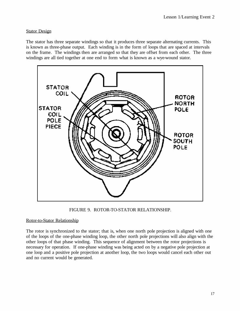
The stator has three separate windings so that it produces three separate alternating currents. Thisis known as three-phase output. Each winding is in the form of loops that are spaced at intervalson the frame. The windings then are arranged so that they are offset from each other. The threewindings are all tied together at one end to form what is known as a wye-wound stator.
FIGURE 9. ROTOR-TO-STATOR RELATIONSHIP.
Rotor-to-Stator Relationship
The rotor is synchronized to the stator; that is, when one north pole projection is aligned with oneof the loops of the one-phase winding loop, the other north pole projections will also align with theother loops of that phase winding. This sequence of alignment between the rotor projections isnecessary for operation. If one-phase winding was being acted on by a negative pole projection atone loop and a positive pole projection at another loop, the two loops would cancel each other outand no current would be generated.
17

Lesson 1/Learning Event 2
Common Alternator Designs
FIGURE 10. WOUND-POLE ALTERNATOR.
Wound-Pole AlternatorAlternate polarity occurs on successive poles. Pole excitation current is obtained through slip rings.The advantages of the wound-pole alternator are a wide-speed range: output current windings arestationary, and the slip rings carry low field excitation current. Disadvantages are: brushes and sliprings wear, are affected by contamination, produce contaminating carbon dust, may cause voltagemodulation, and are not reliable for high-temperature, high-altitude, or high-speed applications.
18

Lesson 1/Learning Event 2
Brush arc is an explosion hazard; fuel or oil cannot be used safely as a coolant. The rotor windingis hard to cool and is relatively unreliable in high-speed or rough-drive applications that cause stresson rotor windings and insulation. The woundpole alternator has an extensive history ofdevelopment but is best suited for low-speed applications in a limited range of environments.
Lundell Alternator
The Lundell rotor develops a field by placing the excitation windings around the axis of the rotorshaft, resulting in each end of the shaft assuming a polarity. Coupled to each end are interspacedfingers forming opposite polarities that provide an alternating field when rotated. Field excitation isachieved through slip ring conduction. Advantages of the Lundell rotor are a simple rotor windingconstruction and stationary output current windings. Disadvantages are windage (air resistance)losses and the use of slip rings and brushes.
19

Lesson 1/Learning Event 2
FIGURE 11. LUNDELL INDUCTOR.
20

Lesson 1/Learning Event 2
Lundell Inductor
This generator type differs from the previously described Lundell type, in that the rotor contains nowindings. Excitation is induced in the rotor poles by stationary field coils located at the ends of therotor. This results in elimination of slip rings and rotating windings. Further advantages can beobtained by casting a nonmagnetic material around the pole fingers, thus producing a smooth rotorwith low-windage losses and high-speed capability. An inherent design requirement of thisstationary field arrangement is the inclusion of an auxiliary air gap in the magnetic circuit. Thisrequires greater field current for excitation.
A Lundell inductor has several advantages. There are no contamination problems or slip ring wear,and the unit is inherently explosion proof. The rotor can be solid and permanently balanced. Allwindings are stationary and readily accessible for cooling. The low-rotor mass reduces bearing loadsand permits rapid acceleration. The bearing center-to-center distance is minimized by theelimination of slip rings and this, combined with a large shaft diameter, permits high-speedoperation. The field windings are simple, bobbin-wound coils permitting short mean turn length.The only disadvantage is that extra air gaps in the magnetic circuit require increased excitationpower.
21

Lesson 1/Learning Event 2
FIGURE 12. INDUCTOR ALTERNATOR.
22

Lesson 1/Learning Event 2
Inductor Alternator
An inductor alternator employs a fixed, nonrotating field coil that induces excitation in the centralportion of the rotor as if it were a solenoid. Each end of the rotor assumes a polarity.A multilobed segment is attached to each end of the rotor. The segment varies the reluctance inthe magnetic circuit as it rotates. As a result, the fixed stator poles experience a variation inmagnetic strength or coupling and produce a resulting output voltage in the stator coils. In contrastto other types of generators, the iron does not experience a flux reversal. Consequently, there isonly a 50-percent use of iron in the stator. Advantages of an inductor alternator are easier windingconstruction for field and stator coils; simplified cooling; it is brushless; and it has an integral solidrotor without windings that permits high-speed operation. Disadvantages of an inductor alternatorare that it has less than 50 percent use of iron, resulting in a heavier unit and the increased total airgap in the magnetic circuit requires more excitation
AIR-COOLED GENERATOR
FIGURE 13. AIR-COOLED GENERATOR.
In tank-automotive applications, air cooling is the most common method. The usual arrangementconsists of a fan that forces air through the alternator to cool the rotor, stator, and rectifier.
23

Lesson 1/Learning Event 2
The major advantage of air cooling is that the generator and cooling are self-contained, drawing airfrom the environment. However, fan power requirements can become excessive at high speedsbecause fan designs usually are structured to provide sufficient cooling at the lowest speedcorresponding to rated output. Fan power at high speeds then appears as a severe reduction ingenerator efficiency. Another factor is that, unless it is filtered, cooling air can deliver abrasiveparticles, water, or other substances to the generator interior. Furthermore, rotor and stator designmust permit unrestricted passage of air through the generator. This can be accomplished bydesigning passages through the rotor and stator. However, roughness in the surface of the rotorcontributes to windage losses, further affecting unit efficiency.
AC GENERATOR REGULATION
FIGURE 14. AC AND DC REGULATOR COMPARISON.
The regulation of AC generator output, though just as important as the regulation of DC generatoroutput, is much simpler for the following reasons:
24

Lesson 1/Learning Event 2
− The AC generator, because of its rectifier bridge, willnot allow current to backflow into itduring shutdown. This eliminates the need for a cutout relay.
− The AC generator will limit its current automatically by regulating the voltage. A currentregulator, therefore, is not needed in the voltage regulator.
Because a cutout relay and a current regulator are not necessary, an AC generator voltage regulatorcontains only a voltage regulation element. The illustration shows a typical single-element voltageregulator for an AC generator and, for comparison, a typical three-element voltage regulator for aDC generator.
25

Lesson 1/Learning Event 2
VIBRATING POINT REGULATOR
FIGURE 15. VIBRATING POINT REGULATING CIRCUIT.
Description
The vibrating point voltage regulator is a single-element unit that limits system voltage. Theelement consists of a double set of contact points that are operated by a magnetic coil. The centercontact is stationary and connected directly to the generator field. The upper and lower contactpoints are pulled downward by the magnetic coil against the force of a spring. The upper andlower contacts always maintain the same distance from each other. The upper contact is shunteddirectly to the ground.
26
Lesson 1/Learning Event 2
The lower contact connects to battery voltage as does the operating coil. A resistor is connectedfrom the battery to the field connection.
Operation
The lower contact normally is connected to the center contact because of spring tension. As themagnetic coil is energized, the movement of the upper and lower contacts will disconnect thecenter and lower contacts. As they move further, the upper contact will become connected to thecenter contact.
As the operation begins, the center contact is connected to the lower contact, sending full batteryvoltage to the field winding. This will cause the alternator to produce full output.
As the alternator raises system voltage, the force exerted by the magnetic coil increases. Thiscauses the upper and lower contacts to move, which, in turn, breaks the connection between thecenter and lower contacts. The field then receives reduced voltage from the resistor, causing acorresponding reduction in alternator output. The resulting lower system voltage decreasesmagnetic coil force, allowing the lower and center points to come together again. This is aconstantly repeating cycle (many times a second) that serves to limit electrical system voltage. Themagnetic coil force and spring tension are calibrated to maintain the desired voltage, which isusually approximately 13.2 to 13.8 volts in commercial vehicles.
During periods of light electrical loads, particularly at high speeds, the system voltage may go toohigh even with reduced field voltage from the resistor. When this happens, the magnetic coil willpull the upper contact into connection with the center contact. This will shunt all field current toground, causing the alternator to stop producing current.
27

Lesson 1/Learning Event 2
TRANSISTORIZED POINT REGULATOR
FIGURE 16. TRANSISTORIZED VOLTAGE REGULATOR.
Operation
This regulator operates essentially the same as the vibrating point regulator. The main difference isthat the contacts only carry a current that is used to trigger a transistor. Based on this signalcurrent from the points, the transistor will control and carry the field circuit. The advantage of thisconfiguration is increased contact point life, because the signal current to the transistor is low andcauses very little arcing.
28

Lesson 1/Learning Event 2
SOLID-STATE VOLTAGE REGULATOR
FIGURE 17. SOLID-STATE REGULATOR CIRCUIT.
Operation
This regulator is a static unit that is totally electronic in operation. In this configuration, thecontact points are replaced by zener diodes. The zener diodes produce a signal to the base of atransistor whenever the electrical system voltage reaches the desired level. This signal reduces orshuts off field current to reduce or stop alternator output. When thesystem voltage drops again, thetransistor
29

Lesson 1/Learning Event 2
again will allow alternator output. This cycle will repeat itself as much as 2,000 times per second.Some applications use a rheostat to adjust the resistance of the field current, thereby regulatingalternator output. The solid-state regulator virtually has replaced the mechanical units in allcurrently produced equipment due to the extreme reliability and low manufacturing costs of solid-state components. Another desirable feature of a solidstate regulator is that it can be made smallenough to be built into the alternator.
30

Lesson 1
PRACTICE EXERCISE
1. The field windings in a DC generator are wound around thea. armature.b. pole shoes.c. frame.
2. The magnetic field in an automotive generator is created bya. permanent magnets.b. electromagnets.c. bar magnets.
3. What type alternators are used on military wheeled vehicles?a. Single-phaseb. Two-phasec. Three-phase
4. The most common method of alternator cooling isa. oil.b. air.c. water.
5. What is one advantage of a solid-state voltage regulator?a. It can be built into the alternatorb. It is interchangeable with the relay typec. It can be easily repaired
31

Lesson 1
ANSWERS TO PRACTICE EXERCISE
1. b (page 7)2. b (page 7)3. c (page 16)4. b (page 24)5. a (page 30)
32

Lesson 2
LESSON 2CRANKING SYSTEMS
TASK
Describe the application of the fundamentals of electricity to starting system components.
CONDITIONS
Given information on the principles, operation, and construction of cranking motors and starterdrives.
STANDARDS
Answer 70 percent of the multiple-choice test items covering cranking systems.
REFERENCES
TM 9-8000
Learning Event 1:
DESCRIBE THE PRINCIPLES, CONSTRUCTION, AND OPERATION OF CRANKINGMOTORS AND STARTER DRIVES
INTRODUCTION
The automotive electrical system includes a starter motor which has replaced the hand crank usedto start cars in bygone days. The purpose of the starter (also called cranking) motor is to rotate theengine crankshaft so the engine can start and begin to operate under its own power. The startermotor is a lowresistance, direct current motor producing a high torque. It draws the current directlyfrom the battery.
33

Lesson 2
PURPOSE OF CRANKING MOTORS
Motors, like generators, are simply a means of changing energy from one form to another. In agenerator, we take the mechanical energy of the turning pulley and change it to electrical energy. Acranking motor does just the opposite of the generator. Electrical energy sent to the motor ischanged to mechanical energy to crank the engine. A practical motor must produce continuousrotary motion. In addition, it must develop a twisting or turning force called torque. In this lesson,we will see how the starter motor develops torque and how it is used to crank the engine.
PRINCIPLES OF MOTORS
The magnetic principle of attraction and repulsion, or unlike poles attract and like poles repel, is theprinciple applied in the development of the electric motor. Remember that a wire carrying anelectric current produces a magnetic field. When this wire is placed in the magnetic field ofanother magnet, mechanical motion is produced because the magnetic field around the wire isrepulsed (pushed away) by the field around the other magnet.
Mechanical Motion Produced by Magnetic Repulsion
Lines of force move from the north pole to the south pole and travel in almost straight lines. Infact, the lines would be straight if the ends of the magnets were flat instead of curved. Themagnetic lines of force moving between the north pole and the south pole of any magnet alwaystake the easiest path or route. The easiest path between the two poles is usually a straight line,because a straight line is also the shortest path.
Remember, each of the magnetic lines of force moves parallel (side by side) to the other lines offorce. They will not cross each other.
The lines of force act a lot like rubberbands. If you stretch the bands between two pegs, they tendto straighten out. Push down on the stretched rubberbands with your finger. If the bands arestretched tight, you can feel them pushing back against your finger. Now move your finger awayquickly. The rubberbands will snap back to form straight lines again. Think of the magnetic linesof force between the two poles of a magnet acting the same way as do the stretched bands.
34

Lesson 2
FIGURE 18. SIMPLE DC MOTOR.
The illustration shows the lines of force around a current-carrying conductor (wire). The + symbol onthe end of the wire means the current is flowing away from you as you view the wire. With the currentflowing in that direction, the lines of force in the magnetic field around the wire are movingcounterclockwise (note the arrows on the lines of force). If the current is flowing toward you as youview the wire, the lines of force would be moving clockwise. In other words, the polarity would bereversed.
35

Lesson 2
If a current-carrying wire is placed in a magnetic field as in Figure 18, notice what happens to thelines of force that are moving from the north pole to the south pole of the magnet. They areforced to bend, just as the stretched rubberbands were forced to bend when you pressed on themwith your finger. The lines of force traveling from north to south bend down in this case becausethey are pushed downward by the counterclockwise rotation of the lines of force around thecurrent-carrying wire. Because the lines of force from the north to south pole pieces of the magnettry to straighten out like the rubberbands, they force the current-carrying wire up (note the arrow).The current is moving in the opposite direction in the wire, and the magnet's lines of force pushdown on this wire.
In the starter motor, like the generator, increasing the strength of the pole shoes will increase thenumber of lines of force. Likewise, increasing the current flow through the wire will increase thestrength of the magnetic field around the wire.
When these magnetic forces oppose each other, they try to push each other away. The opposingforces can be very great if the wire is carrying enough current to make the magnetic field verystrong.
Now let us bend a wire to form a loop and place the loop in a magnetic field. Nothing happensuntil we send current through the loop. If we send current flowing through the loop, the magnet'slines of force push up on the right side of the loop and down on the left side. This produces thetorque to rotate the entire loop counterclockwise (to the left). Actually, the loop would probablymove only one-fourth of a revolution (90ø) because it would be out of the magnetic field of themagnet. The loop would then be straight up and down instead of straight across as shown.To get continuous rotation, we need a magnetic field large enough to contain the loop. We wouldalso need commutator bars and brushes like we had in the generator.
Of course, a single loop would not produce enough torque to crank the engine. But, by using manyloops, each with its own commutator bars, we can have a cranking motor that will produce all ofthe torque needed.
36

Lesson 2
Most starter motors are series motors. They are called series motors because the rotating loop andthe windings around the magnetic poles are connected in one (series) path. The current flowingthrough the loop also flows through the windings. In an actual motor, the windings around thepole shoes are called field windings because they help produce the magnetic field. The purpose ofthe field winding is to produce a strong magnetic field so that the loop will receive a more powerfulpush. The poles are curved so the conductors of the loop can pass as close as possible to the polesas they move past. Since the magnetic field is strongest near the poles, the conductors in the loopsare given a stronger push.
In an actual cranking motor, there are many rotating loops all assembled into an armature. Thearmature consists of a shaft on which a laminated iron core and commutator are mounted. Theloops, or windings, of the armature are mounted in the core and are insulated from one anotherand from the core. The commutator segments have riser bars, like the generator, to which theends of the armature windings are connected by soldering.
37

Lesson 2
CRANKING MOTOR CONSTRUCTION
FIGURE 19. TYPICAL STARTING MOTOR.
The vehicle cranking motor has only one job to do, which is to turn the crankshaft at a speed fastenough to start the engine. Since there are many different types and sizes of engines, there aremany types and sizes of cranking motors. The common starter motor used on military vehiclesconsists of the following five main assemblies: armature, field and frame, commutator-end head,drive-end housing, and drive mechanism. The field windings, frame, and armature are almost thesame as in the generator which you have already studied, except that in the starter motor thewindings are much heavier in order to carry a lot of current. The commutator-end head houses thebrush holders, brushes, and a bearing. The drive-end houses the drive mechanism and usually themounting flange to mount the starter to the engine.
38

Lesson 2
STARTER DRIVES
The starter usually drives the engine through a pinion (small) gear mounted on the starter motorarmature shaft. When the starter motor is running, the pinion gear engages (meshes) with a largegear mounted on the rim of the engine flywheel.
Two types of starter drive mechanisms in common use are the Bendix drive and the overrunningclutch drive.
FIGURE 20. BENDIX STARTER DRIVE.
The Bendix drive consists of a threaded sleeve, which is fastened to the armature shaft by meansof a drive spring, and a drive pinion, which is threaded on the sleeve. The pinion has a weight onone side to make it unbalanced. Think of the sleeve as a bolt and the pinion as a nut threaded tothe bolt. A weight is attached to the nut. If we spin the bolt, the nut, because of the weight, triesto stand still. However, the spinning bolt would force the nut to move forward or backward on itsthreads, depending on which way the bolt was spinning.
39

Lesson 2
Suppose the armature has started to turn, and the pinion, which is not turning because of theweight on one side, is moving toward the flywheel ring gear. The teeth on the pinion gear havemeshed (engaged) with the teeth on the ring gear. The pinion has reached its stop and cannotmove any further on the threaded sleeve. It is now locked to the sleeve and must turn with it. Thenow rotating pinion turns the flywheel gear, which in turn rotates the flywheel ring gear and enginecrankshaft.
As soon as the engine starts, its speed of rotation is faster than that of the pinion. The ring gearnow drives the pinion because it is turning faster. The pinion then moves back on the threadedsleeve and disengages from the ring gear.
Sometimes the engine starts but fails to continue to run; however, the few turns that it does runmay be enough to force the Bendix drive pinion out of mesh. To keep this from happening, a newtype of Bendix drive is used on some late model vehicles. This drive is called the Bendix Folo-Thru. Inside the drive is a spring-loaded pin. When the pinion moves to engage the flywheel gear,the pin enters a notch on the threaded sleeve to hold the pinion in mesh. As long as the engineturns slowly, the pinion will be held in mesh with the flywheel by the pin in the notch on thesleeve. After the engine starts and is operating at a speed of about 400 RPM, the pinion, which isnow spinning at a rate of several thousand RPM, will force the pin out of the notch on the sleeve.The pinion can then move back on the threaded sleeve away from the flywheel.
In the overrunning clutch type starter drive, the pinion is shifted into engagement with the flywheelwith a lever.
The drive for the overrunning clutch has internal (inside) splines which fit external splines on thestarter armature shaft. The drive pinion is attached to a rotor which forms the inner half of theoverrunning clutch.
40

Lesson 2
FIGURE 21. OVERRUNNING CLUTCH.
Now look at the end view of the overrunning clutch, which is really a one-way clutch. It can drivein one direction, but not the other. The outer shell is part of the splined sleeve, so it rotates whenthe starter armature rotates. The only connection between the shell and the rotor are the fourspring-loaded rollers between them. Notice the rollers are in slots in the sleeve. They can moveback and forth in the slots. The slots are tapered slightly. When the sleeve starts to rotate, therollers move in their tapered slots to a point where they become wedged (jammed) between thesleeve and the rotor. Then the whole clutch turns as a single unit. When the engine cranks, therollers are forced to move the other way in their slots, because the pinion and rotor are nowtraveling faster than the overrunning clutch sleeve.
You can easily test the action of the clutch by gripping the sleeve with one hand and the pinionwith the other. Try to turn the pinion in either direction. You will find you can turn it one way,but when you try to turn it the opposite way, it locks. In fact, if you can turn it both ways, it isdefective and must be replaced.
A shift lever (also called a yoke lever) is used with the overrunning clutch to shift the starter pinioninto mesh with the flywheel gear. The lever may be operated manually through linkage or by anelectromagnet.
41

Lesson 2
The gear reduction obtained by having a small starter pinion gear drive the large flywheel gear isusually about 12 to 1 or more. This means the rotational speed of the starter armature is about 12times that of the flywheel when the engine is being cranked. The pinion gear on the armature shaftmeshes directly with the gear teeth on the flywheel. In some instances, however, a doublereduction is needed. Here the final gear ratio may be as high as 25 to 1 or even 40 to 1. Withdouble reduction, the gear on the armature shaft does not mesh directly with the teeth on the fly-wheel, instead they mesh with an intermediate gear that drives the flywheel driving pinion. Thisdouble reduction drive permits the use of a small starter motor to turn a fairly large engine.
If the overrunning clutch type drive is used, we must have a shift fork and linkage to shift thepinion into mesh with the flywheel gear. As we have already said, this linkage may be operatedmechanically or electrically. If it is electrically operated, a unit called a solenoid is used.
A solenoid is an electromagnet with a movable core or plunger. It is mounted on top of the startermotor. When the starter switch on the vehicle instrument panel is depressed (in some cases a key-operated switch is used), the windings in the solenoid create an electric magnet.
When the shift plunger is in its released position, being held there by the contact plunger spring, nocurrent is flowing because the switch for the solenoid winding is open. The starter pinion is notengaged with the flywheel. When the switch to the solenoid windings is closed, the solenoid coil isan electromagnet. The electromagnet pulls the solenoid plunger to the left. This action shifts thepinion into mesh with the flywheel and then closes the starter switch. Now current flows throughthe starter motor causing the armature to rotate.
When the switch for the solenoid winding is opened, the spring pushes the plunger back. Thisbreaks the circuit to the starter and pulls the pinion back away from the flywheel.
WATERPROOF STARTERS
Military tactical vehicles that are expected to ford water deep enough to cover the starter havewaterproof starters. Such starters are completely sealed so that no water can enter. Bearings arelubricated on original assembly and need no attention between overhauls.
42

Lesson 2
The Autolite starting motor, model MCZ 4005UT, is a typicalstarter motor in use today on military vehicles. It is a sealed type (waterproof) starter and is usedon the 1/4-ton truck M151.
The motor operates on 24 volts and is a four-pole, four-brush unit. It is designed for underwateroperation but is not completely waterproof unless it is used with a waterproof flywheel housing. Agasket is used to seal the starter to the flywheel housing. The starter is mounted on two flywheelhousing studs and held in place by two nuts and two lock washers.Three bushing-type bearings which require no lubrication are used to support the armature shaft.There is one bearing in each end plate, and one in the flywheel housing of the engine. The starterdrive is the Bendix Folo-Thru type.
The end play of the armature shaft is held within allowable limits by the use of thrust washers ofvarious thicknesses. The pole pieces (soft iron shoes) are attached to the starter frame bycountersunk screws. The field winding or coils are positioned around two of the pole pieces,opposite to each other. This gives a four-pole action with only two field windings. The internalresistance is kept low because there are only two windings.
When the starter switch is closed, current is passed through the two grounded brushes to thecommutator, which is located on the armature shaft. The armature has a number of heavy wireswound around it in such a manner as to produce a magnetic field. After flowing through thearmature windings, the current is directed through two insulated brushes to the two field windingsand the pole pieces become magnetized. The magnetic fields of the pole pieces oppose themagnetic field of the armature, causing the armature to rotate. The direction of rotation iscounterclockwise as viewed from the drive end of the starter. This direction of rotation is oppositeto that of most starters, but this starter is mounted over the transmission instead of being mountedon the engine.
43

Lesson 2
THIS IS A BLANK PAGE
44

Lesson 2
PRACTICE EXERCISE
1. The starter motor is a device that changesa. electrical energy into mechanical energy.b. mechanical energy into electrical energy.c. torque into rotational speed.
2. What is required for continuous rotation of the starterarmature?a. High output torqueb. Commutator bars and brushesc. Alternating field current
3. What is mounted in the laminated iron core of the startermotor armature?a. Armature windingsb. Commutator barsc. Armature brush holders
4. What type of winding is used in most starter motors?a. Shuntb. Seriesc. Compound
5. Magnetic lines of force move parallel to each other anda. are not affected by other magnetic fields.b. always oppose each other.c. will not cross each other.
45

Lesson 2
ANSWERS TO PRACTICE EXERCISE
1. a (page 33)2. b (page 36)3. a (page 37)4. b (page 37)5. c (page 34)
46

Lesson3/Learning Event 1
LESSON 3IGNITION SYSTEMS
TASK
Describe the application of the fundamentals of electricity tothe components of a wheeled vehicle battery ignition system.
CONDITIONS
Given information on the construction and operation of ignition coils, distributors, secondarywiring, spark plugs, and advance mechanisms.
STANDARDS
Answer 70 percent of the multiple-choice test items covering ignition systems.
REFERENCES
TM 9-8000
Learning Event 1:DESCRIBE THE PRINCIPLES OF BATTERY IGNITION SYSTEMS
INTRODUCTION TO IGNITION SYSTEMSThe simple act of walking into a darkened room, flipping a light switch, and illuminating thepreviously darkened room is something we take for granted in our everyday lives. We neverconsider the vast electrical network that is involved in making the light come on.
Let's discuss a few factors involved in this seemingly simple act.
First of all, the house must be provided with an electrical source of power. This often originates ata hydroelectric plant that consists of a huge dam to retain a lake of water pressure and hugegenerators to convert the water pressure to electric power.
47

Lesson3/Learning Event 1
This power is then carried by high-voltage wires to a step-down transformer near your home. Thisreduced voltage is transferred through wires to the fuse box in your home. From the fuse box, theelectrical power is carried by wires to the switch you flipped and eventually to the light fixture thatprovided the illumination for the room.
When you step into your car and start it, you again perform what appears to be a simple act. Youmerely turn the ignition switch to the start position until the engine is running and then release theswitch. Now, let's see what was actually involved in this act.
From previous studies, you know that a spark produced at the instant the fuel-air mixture of acylinder is compressed to the proper pressure will cause a combustion that will drive the pistondown.
We also know that when that piston returns to the same position again, another spark will ignitethe mixture again.
Just think how fast these sparks must occur at just the right instant in an eight-cylinder enginerunning at 4,000 RPM.
The ignition system is one of the most interesting (and troublesome) systems found on a gasolineengine. It is interesting because it must build up the vehicle's battery voltage from about 24 voltsor less to as much as 25,000 or 30,000 volts, and it must do this many times per second. It istroublesome because so many things can and do go wrong in the system.
To give you some idea about how fast the ignition system builds up the battery voltage to as muchas 30,000 volts at the spark plug, let us take a six-cylinder engine turning at 4,000 RPM and seewhat the ignition system is doing. As you know, in a fourstroke cycle engine, one-half of thecylinders fire during each revolution of the crankshaft. This means that three cylinders of a six-cylinder engine will fire during each revolution. By multiplying the number of RPM by the numberof cylinders firing each revolution, we find that the ignition system in our example must deliver 3 x4,000 or 12,000 high-voltage surges or sparks per minute. This is equal to 200 sparks per second.
48

Lesson3/Learning Event 1
The ignition system not only builds up these high-voltage surges to fire the fuel-air mixture in theengine cylinders, it also times or paces these surges so they will occur in each cylinder just as thepiston reaches the end of its compression stroke. So we can say that the ignition system has thejob of building up high-voltage surges and timing them to occur in each cylinder at precisely theright instant. How this is done is the story of each ignition system.
The intent of this lesson is to provide you with a knowledge of the construction and operation ofthe components in an ignition system that provide the spark needed to make an engine run.
BATTERY IGNITION SYSTEM COMPONENTS
Although other things are usually added, the basic ignition system consists of the following items:
The vehicle's battery or batteries and the generator to supply the required current. While theengine is being cranked, the batteries supply the low-voltage current to the ignition system. Whenthe engine is running and the generator is charging, it takes over the job of supplying current to thesystem.
The ignition switch opens and closes the circuit between the batteries and the other components inthe ignition system. We usually stop the engine by turning off (opening) the ignition switch.
The ignition coil is the device that converts the low voltage from the batteries to the high voltageneeded to ignite the fuelair mixture in the engine cylinders.
The ignition distributor alternately opens and closes the low-voltage circuit through the coil. It alsoreceives high-voltage surges from the coil and distributes them to the proper cylinders to burn thefuel-air mixture. The low-voltage circuit is better known as the primary circuit, while the high-voltage circuit is better known as the secondary circuit. In the remainder of this lesson, we willrefer to them as the primary and secondary circuits.
High-tension (voltage) wires carry high-voltage surges to the spark plugs.
49

Lesson3/Learning Event 1
Spark plugs provide an air gap in each cylinder for the highvoltage surges to arc across, which is thereason we need such high voltage in the secondary circuit. It takes a lot of voltage to force thecurrent to jump across the air gap between the electrodes of a spark plug. The current, arcingacross the air gap, is what actually ignites the fuel-air mixture.
The primary circuit consists of the components between the battery and the breaker points,including the breaker points.
The secondary circuit consists of the secondary winding in the coil, the distributor cap and rotor,the distributor, spark plug wires, and spark plug.
50

Lesson3/Learning Event 2
Learning Event 2:DESCRIBE THE CONSTRUCTION AND OPERATION OF IGNITION SYSTEMCOMPONENTS
IGNITION COIL
The ignition coil is really a step-up transformer. You have probably noticed transformers on thelight wire poles near your home. These are usually step-down transformers which change the highvoltage in the transmission wires on the poles to the 110volt current you use in your home. Ourignition coil does just the reverse of the step-down transformer. It changes the low voltage suppliedby the battery or the generator to the high voltage needed at the spark plugs.
To understand how a coil works, let us review the relationship between electricity and magnetism.We know that when current flows through a conductor, a magnetic field is created around theconductor. The strength of the magnetic field depends on the number of loops or coils of wire andthe amount of current flowing through them.
Magnetic fields differ in their flux paths when there is a single, double, or multiple coil of wirecarrying the current.
We can make a magnetic field stronger simply by increasing the number of coils or turns of thewire.
The strength of the magnetic field around the coil can also be increased in two other ways. First, itcan be strengthened by increasing the amount of current flowing in the coil; second, it can bestrengthened by inserting a soft iron core inside the coil of wire. Placing a soft iron core in thecenter of the coil will provide an easier path for the magnetic lines of force, or, to put it anotherway, the core will increase the number of lines of force because it will reduce the resistance in themagnetic field. It is much easier for the lines of force to travel through an iron core than throughthe air.
Now, recall that a magnetic field can induce current into a conductor, provided the conductor ismoved through the field or the field is moved across the conductor. In the case of our coil,however, as long as direct current flows through the conductor, no current will be induced becausethere is no relative movement between the coil and the magnetic field.
51

Lesson3/Learning Event 1
FIGURE 22. IGNITION COIL CONSTRUCTION.
Now let's study the construction of the coil. The illustration shows a coil that has been cut away toshow the primary winding, secondary winding, soft iron core, and the terminals for the windings.The primary winding is the large wire, and the secondary winding is the small wire. The actualdiameter of the wire used in the secondary winding of the coil is about the same as one of thehairs on your head, or less than 0.005 of an inch. With such a small wire, we can have thousandsof turns of wire in the secondary winding in a small space.
One end of the secondary winding is connected to the high-tension lead of the secondary terminalon top of the coil, while the other end is usually connected to one end of the primary winding,although it may be grounded to the metal can that surrounds the coils and the core.
52

Lesson3/Learning Event 2
There are two terminals in the coil assembly for the primary winding. One terminal is connectedto the wire from the ignition switch which connects and disconnects the coil from the battery. Theother terminal is connected to the movable breaker point in the distributor.
When the ignition switch and breaker points are closed, current flows through the primary windingof the coil. The current flowing through the few hundred turns of the primary winding builds up astrong magnetic field. This field surrounds the primary and the secondary windings and makes theiron core a strong electromagnet.
Remember, to induce a voltage into a conductor we must have a magnetic field and relative motionbetween the conductor and the magnetic field. We do get relative motion between the field andthe conductors when current starts to flow in the primary windings, but this buildup is too slow toinduce a voltage in the secondary winding that is strong enough to jump the air gaps in thedistributor cap and spark plugs. When the magnetic field reaches its maximum strength, there isno relative motion between it and the windings, so no current will be induced in the windings.
Suppose we suddenly shut off the current flowing through the primary winding by opening thebreaker points. The magnetic field would collapse and disappear. As it collapses, its lines of forcewould cut across the primary and secondary windings at tremendous speed. The lines of forcecollapsing across the windings would induce a voltage into each turn of the coil's windings. Voltageinduced into the primary winding is called self-induced voltage because the magnetic field wascreated by the primary winding in the first place. Voltage induced in the secondary winding is theresult of what is called mutual induction. The secondary winding did nothing to create themagnetic field, but a voltage is induced into it because it is "mutually" located with the primarywinding.
53

Lesson3/Learning Event 1
How much voltage will be induced into the primary and secondary windings by the collapsingmagnetic field? Well, that will depend on the speed with which the field collapses (speed of themotion) and the number of turns of wire in each coil. The more turns of wire in the windings, thegreater the induced voltage will be. In the primary winding of most automotive coils, there are afew hundred turns of wire and the voltage induced will be about 200 or 250 volts. Because theprimary circuit is now open (that is why the magnetic field collapsed), this voltage is not goinganywhere except into the capacitor, which we will study later. While the magnetic field iscollapsing across the few hundred turns of primary winding, it is also moving across the thousandsof turns of secondary winding. Voltage induced into each turn of each winding is about the same.Since the secondary winding has many more turns, the total voltage induced into it will be in thethousands of volts. This voltage is high enough to force current to flow out of the coil, throughthe secondary terminal, and through the conductors to the spark plug in the cylinder. There thecurrent is forced, by the high voltage, to jump the air gap and ignite the fuel mixture. This currentthen returns to its source, in this case the secondary winding of the coil.
IGNITION DISTRIBUTOR
We stated earlier in this lesson that the ignition distributor has two separate and distinct jobs to do.One job involved the primary circuit, while the other job was concerned with the secondary circuit.Let us discuss the primary circuit first. The parts we will discuss are the distributor breaker points,distributor cam, and the capacitor (condenser).
54

Lesson3/Learning Event 2
FIGURE 23. TYPICAL AUTOMOTIVE IGNITION SYSTEM.
The points consist of two contacts: one is stationary and grounded and the other is insulated andmovable. When mounted in the distributor, the spring end of the movable breaker arm assembly isconnected to the primary lead from the coil. The breaker arm is mounted on a pivot post and isinsulated from the post by a fiber bushing. The entire arm can swing back and forth on the pivotpost. A fiber rubbing block is kept in contact with the distributor cam on the distributor shaftduring the time the breaker points are open. The distributor shaft is driven in time with and atone-half the speed of the engine crankshaft. On most distributors, the cam will have one cam lobefor each cylinder of the engine. The grounded point is attached to a support which, in turn, ismounted on a plate inside the distributor. While this point is often called the stationary point, itcan be moved to adjust the point opening. This is done by moving the adjust able point eithernearer to or farther from the insulated point.
55

Lesson3/Learning Event 1
On some distributors, the adjustable point is moved in the support to make the adjustment. Inother applications, the support is moved. Let's see just what happens with these parts when thedistributor is in operation.
While the low side of the cam is toward the rubbing block, the breaker arm spring holds thecontact points closed. At this time, current can flow from the batteries to ground, then from thegrounded contact to the insulated contact. From here it will flow out through the primary windingsof the ignition coil. This causes a strong magnetic field to build up around the coil. From theprimary of the coil, current returns through the closed ignition switch to the battery.
Current will continue to flow as long as the circuit is closed. When the cam turns enough, a lobeon the cam will contact the rubbing block, then push the contact points open. This opens theprimary circuit, and the magnetic field rapidly collapses around the windings in the coil. As thecam continues to turn, the lobe will move from under the rubbing block. At this time, the springwill again close the points. As each lobe in turn strikes the rubbing block, the above action takesplace.
So far, we have seen how the magnetic field builds up in the ignition coil while the points areclosed. Also, when the cam lobe opens the points, the circuit is broken and the coil's magneticfield collapses. This induces a very high voltage in the secondary winding of the coil. This highvoltage forces current to jump the air gap at the spark plug electrodes and ignite the fuel-air mixturein the cylinder.
In practice, however, creating the high voltage in the coil is not quite so simple. Actually,electricity, like anything else in motion, tries to remain in motion. It resists any effort to change orstop its flow. Also, the magnetic field in the coil is collapsing around the primary windings as wellas the secondary. This builds up voltage in the primary windings. The end result is that current willarc across the points. This arcing will cause the points to burn and be destroyed in a very shorttime. It also causes the magnetic field in the coil to collapse more slowly. Remember, we get ahigh voltage induced into the coil's secondary windings only if the magnetic field collapses reallyfast.
56

Lesson3/Learning Event 2
To reduce arcing across the points and to speed the collapse of the magnetic field in the coil, acapacitor is used. For years, automotive mechanics have referred to the capacitor as a condenser.As you will see, however, capacitor is a more accurate term. The capacitor consists of two sheetsof metal foil, called plates, which are separated by insulating paper and then rolled together. Oneroll of foil is connected to a wire lead, while the other roll is connected to the metal can or case.
The lead of the capacitor is connected to the same terminal as the insulated breaker point. Thecapacitor case is grounded to the distributor plate by a screw. This is a parallel connection, becausecurrent can go through the points or into the capacitor. When the points are closed, the currentgoes through the points because the foil strips in the capacitor are insulated from each other.
As the cam lobe moves the rubbing block and barely separates the points, the voltage in theprimary windings will start to rise and attempt to force current across the points. The capacitornow offers an easier path for the current to take, so current will flow into the capacitor and chargeit electrically. By the time the current charges the capacitor, the points will have opened wideenough so that the current can no longer jump the gap between the contacts. In this manner, thecapacitor protects the breaker points.
The secondary circuit in the distributor consists of the rotor and distributor cap and is discussed inthe following paragraphs.
The distributor cap is made of Bakelite or some other hard insulating material. It containsterminals (usually called towers) for each spark plug wire and for the high-tension wire from thesecondary terminal in the ignition coil. A contact for each terminal extends through the cap.
The rotor, which is also made of Bakelite, is mounted on and rotated by the distributor shaft. Ithas a flat spring-type conductor that stays in contact with the coil's secondary terminal in the centerof the distributor cap. The spring, in turn, is connected to a blade-type contact on the top of therotor. As the rotor is rotated by the distributor shaft, this contact passes very close to each sparkplug terminal in turn.
57
Lesson3/Learning Event 1
Engines used in the Army's tactical wheeled vehicles are designed to operate under water. Thismeans that the ignition system must be waterproof. The distributor is made waterproof by a covermounted over the distributor cap. The ignition coil is mounted inside the distributor housing and isalso protected from water by the cover. The cover contains threaded waterproof terminals for thespark plug cables.
SECONDARY WIRING AND SPARK PLUGS
The secondary wiring is part of the high-voltage circuit outside the distributor. On civilian-typevehicles, this wiring consists of a cable or wire from the ignition coil to the center tower in thedistributor cap. Other wires will lead from the outside towers to the spark plugs.
The wires themselves are very small, only a few strands of very fine wire. The insulation is verythick to prevent the highvoltage current, traveling through the wire, from arcing to ground before itgets to the spark plug.
Other type cables may use a carbon saturated string, instead of a wire, as a conductor. The mainreason for this is to cut down on noise that can be picked up by radio.
On waterproof ignition systems, the hightension cable will be inside of a waterproof tube. A wovenmetal shielding around this tube will reduce radio interference (static) when the engine is running.A nut and a waterproof seal are used on each end of the cable to make a waterproof connection atthe distributor and the spark plug.
58

Lesson3/Learning Event 2
FIGURE 24. TYPICAL SPARK PLUG CONSTRUCTION AND HEAT RANGE DESCRIPTIONS.
The spark plug (the remaining part of the secondary circuit) consists of a metal shell, a porcelaininsulator with an electrode extending through it, and a ground electrode which is attached to themetal shell. The shell has external threads to allow it to be screwed into a threaded hole leading tothe combustion chamber. The insulated and the grounded electrodes are separated by an air gap(also called a spark gap) of 0.025 to 0.040 of an inch. In operation, the high-voltage currentproduced in the secondary winding of the coil will arc across the spark plug air gap to ignite thefuel.
Spark plugs used in waterproof systems are much like the ones we have just discussed, except thistype plug will be completely surrounded by a metal shell to which the nut on the spark plug cable isthreaded. This shell is for both shielding and waterproofing the spark plug.
Spark plugs are usually classified in two ways: first, as to the diameter of the threaded hole intowhich they are screwed (10 mm, 14 mm, 18 mm, and so forth), and second, according to the heatrange of the plug.
59

Lesson3/Learning Event 1
The heat range, or operating temperature of a spark plug, is determined by the length of theinsulator nose. The spark plug, when in operation, is exposed to the heat of the burning fuel. Forthe plug to cool, the heat will have to pass up through the insulator nose to the shell of the plugand from there to the cylinder head or engine block. The farther the heat has to go to get to theshell of the plug, the hotter the spark plug will operate. This means a spark plug with a shortinsulator nose will operate cooler than one with a long insulator nose.
The correct spark plug for any given engine can vary considerably. A hot plug will work better inan engine that is burning oil or in one that is operated at low speeds or short distances. A colderplug may be needed in the same engine if it is operated at high speed over long distances or underheavy loads.
Examine the insulator nose to determine if a spark plug of the correct heat range is being used. Ifthe deposits on the nose are a light grey or brown ash, the heat range is correct. If the nose iscovered with a black, gummy carbon, the plug is too cold. A blistered nose, or one with theporcelain chipped off, is probably too hot.
Before we go any farther, let us see what happens when all the things we have discussed so far inthis lesson are in operation. Let us start with the number 1 piston going up on the compressionstroke. At this time, the air-fuel mixture in the cylinder is being squeezed into a small area of thecombustion chamber. With the ignition switch and the breaker points closed, a magnetic field isbuilding up in the ignition coil.
When the piston reaches near top dead center on the compression stroke (the exact point willdepend on engine design and engine speed), ignition of the fuel should take place. This is madepossible because the distributor is turning in time with the engine.
60

Lesson3/Learning Event 2
As the cam in the distributor turns, one of the cam lobes will contact the rubbing block on theinsulated point. If the distributor is in proper time with the engine, the contacts will open at thetime the fuel should be ignited. When the contacts in the distributor open, the primary circuit isbroken and the magnetic field collapses. The collapse of the field induces high voltage in thesecondary windings of the coil. This high-voltage current then passes to the center of thedistributor cap and to the rotor. The rotor at this time is in line with the number 1 tower on thedistributor cap. Current passes from the tower to the spark plug wire and on to the spark plug. Asthe engine and distributor continue to turn, the remaining spark plugs receive the high voltage fromthe coil at the proper time and in the proper sequence.
SPARK ADVANCE MECHANISMS
Spark advance mechanisms are necessary for the spark to occur in the combustion chamber atexactly the right instant for all engine speeds. At idle, the spark is usually timed to occur at about2° to 10° before TDC. At high speed, the spark may occur as much as 40° or more before thepiston reaches TDC on its compression stroke. It is necessary to start the fuel-air mixture burningsooner at high speeds because the piston is traveling much faster. In fact, without a spark advance,the piston would be well past TDC and moving downward before the burning fuel-air mixturecould create enough pressure for an effective power stroke.
There are two types of advance mechanisms in common use that will cause the distributor todeliver a spark sooner in the cycle at high speeds. These mechanisms are the centrifugal advanceand the vacuum advance.
61
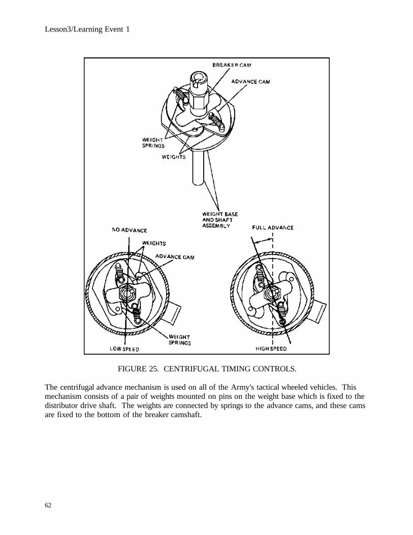
Lesson3/Learning Event 1
FIGURE 25. CENTRIFUGAL TIMING CONTROLS.
The centrifugal advance mechanism is used on all of the Army's tactical wheeled vehicles. Thismechanism consists of a pair of weights mounted on pins on the weight base which is fixed to thedistributor drive shaft. The weights are connected by springs to the advance cams, and these camsare fixed to the bottom of the breaker camshaft.
62

Lesson3/Learning Event 2
Now let's see how this advance mechanism works. With the engine running at an idle speed, thesprings hold the weights in their retarded (no advance) position. As the engine speeds up, theweights try to fly outward; but, to do this, they must first overcome spring tension, which they willdo once the engine is running fast enough. As the engine speeds up, the weights gradually moveout, not all at one time. This gives a smooth even advance.
Let's suppose that the engine has speeded up to its governed speed. At this time, the weights havemoved outward as far as they can. As the weights moved, the hooks on the free end of theweights rotated the distributor cam in the direction of cam rotation. Now, each of the distributorcams will strike the rubbing block on the movable point sooner in the cycle, causing the points toopen sooner. This action causes the spark to occur in the combustion chamber earlier during thecompression stroke of the engine, or advance the time the spark occurs.
63

Lesson3/Learning Event 1
FIGURE 26. VACUUM TIMING CONTROLS.
Vacuum advance mechanisms are not used on tactical wheeled vehicles, but they are commonlyused on civilian-type vehicles and on Army staff cars. This type of advance uses a vacuumchamber which is connected to the intake manifold and a vacuum diaphragm which is linked tothe distributor plate. There is a diaphragm spring on the vacuum side of the diaphragm.
When the engine is not running, air pressure on both sides of the diaphragm is equal. The springpushes the breaker plate to the retarded position.
64

Lesson3/Learning Event 2
When the engine is running and manifold vacuum is high, atmospheric pressure pushes thediaphragm against spring pressure and compresses the spring. The movement of the diaphragmpulls the breaker plate to the full advance position. If the engine is then placed under load or if forsome other reason manifold vacuum decreases, the spring is able to move the diaphragm and retardthe spark.
Although the centrifugal and the vacuum mechanisms do the same thing, they cause spark advanceunder different conditions. Centrifugal advance is controlled entirely by engine RPM. Vacuumadvance responds to varying loads on the engine. When the load is great, there will be little or novacuum advance, because the throttle valve will be open and the manifold vacuum will be low.Most modern high-speed engines in civilian vehicles use both types of advance mechanisms ontheir distributors. When both are used, the spark advance will respond to both engine speed andload.
65
Lesson3/Learning Event 3
DESCRIBE THE PRINCIPLES, OPERATION, AND CONSTRUCTION OF SOLID-STATEIGNITION SYSTEMS
GENERAL
The recent rise of electronic ignition systems is due to the superiority of electronic ignition overconventional ignition systems in several major areas. These systems totally remove one area ofmaintenance from the ignition system, that of the ignition (contact) points. Also, because theelectronic ignition system produces a higher voltage than the conventional system, the electronicignition system usually can fire a fouled spark plug. In the area of high performance, the electronicignition system is far superior in that its voltage does not deteriorate as quickly at high enginespeeds as the conventional ignition system. Because the electronic ignition system does not containignition points that wear, ignition performance does not deteriorate with mileage.
DESCRIPTION
The electronic ignition system differs from that of a conventional ignition system in that it consistsof a special pulse sending distributor, an electronic control unit, a two-element ballast resistor, and aspecial ignition coil. Also, the ignition breaker points and capacitor used in conventional ignitionsystems have been replaced by a gear-like piece called a reluctor and a pickup unit. The reluctorreplaces the distributor cam used in the conventional distributor. The pickup unit is made up of apermanent magnet, a pole piece, and the coil.
OPERATION
The ignition primary circuit is connected from the battery, through the ignition switch, through theprimary side of the ignition coil, to the control unit where it is grounded. The secondary circuit isthe same as in the conventional ignition system. The magnetic pulse distributor also is connectedto the control unit.
66

Lesson3/Learning Event 3
FIGURE 27. SOLID-STATE IGNITION SYSTEM.
As the distributor shaft rotates, the distributor reluctor turns past the pickup unit, and each of theeight teeth (on an eight cylinder engine) on the reluctor pass near the pickup unit once during eachdistributor revolution. As the reluctor teeth move close to the pickup unit, voltage is induced into
67

Lesson3/Learning Event 3
the pickup unit. That is, as a tooth on the reluctor passes the pickup coil, magnetic lines of forceflow from the permanent magnet, through the pole piece, and through the reluctor back to themagnet. Voltage is induced in the windings as these magnetic lines of force pass through thepickup coil. This voltage is carried from the pickup coil to the control unit by the distributor leads.When the pulse enters the control unit, it signals the control unit to interrupt the ignition primarycircuit. This causes the primary circuit to collapse and begins the induction of the magnetic lines offorce from the primary side of the coil into the secondary side of the coil. This induction providesthe required voltage to jump the spark plug gap and ignite the airfuel mixture in the combustionchamber.
As the tooth on the reluctor moves away from the pickup unit, the primary circuit is againcompleted. The magnetic field again is built up in the primary windings of the ignition coil, whereit waits for another signal from the pickup unit.
The buildup and collapse of the primary circuit takes place very rapidly. This is brought about bytransistor action and the speed of the reluctor.
The advantages of an electronic ignition system are that the transistors in the control unit can makeand break the primary circuit much faster than conventional ignition points. Higher primaryvoltages can be used because this system can be made to handle higher voltages without harmfuleffects, whereas ignition points cannot. The quicker switching time of this system allows longercoil primary circuit buildup and longer induction time when the primary circuit collapses. Thisincreased time allows the primary circuit to build up more current and the secondary circuit todischarge more current. The higher secondary current produces a hotter spark at the spark plug,which allows the engine to operate more efficiently.
68

Lesson3/Learning Event 3
CAPACTIVE-DISCHARGE IGNITION SYSTEM
FIGURE 28. CAPACITIVE-DISCHARGE IGNITION SYSTEM.
This system offers several advantages over the other systems.
It is similiar to full transistor-magnetic control, except that certain components have been added tothe primary circuit. These are the power converter, capacitor, and thyristor or siliconcontrolledrectifier (SCR). The power converter has an output voltage of 250 to 300 volts. This voltage isused to charge the capacitor with the thyristor in its off condition. When the thyristor rate (1)receives a signal from the pulse generator, the circuit from the anode (2) to the cathode (3) isclosed, and the capacitor immediately discharges at a high rate through the primary. A highsecondary voltage can be reached about 100 times faster with the capacitive-discharge system thanwith the inductive systems. This decreases spark plug fouling, materially increasing potential sparkplug life. Another advantage is that it uses less current than either the conventional system or theother solid-state systems. This means less demand on the battery during starts and a potentiallylonger battery life.
69

THIS IS A BLANK PAGE
70

Lesson3
PRACTICE EXERCISE
1. The secondary winding in an ignition coil is usually grounded to the
a. coil base.b. primary winding.c. iron core.
2. The capacitor is connected in
a. parallel with the points.b. series with the points.c. series-parallel with the points.
3. A vehicle that is usually driven at high speeds will probably
need a spark plug with aa. built-in resistor.b. long insulator nose.c. short insulator nose.
4. Solid-state ignition systems use
a. breaker points and a capacitor.b. a reluctor and pickup unit.c. a relay and a resistor.
5. The weight base of the centrifugal advance mechanism is fixed
to the distributor'sa. drive shaft.b. camshaft.c. breaker plate.
71

Lesson 5
ANSWER TO PRACTICE EXERCISE
1. b (page 52)2. b (page 57)3. c (page 60)4. b (page 66)5. a (page 62)
72

Lesson 4/Learning Event 1
LESSON 4ACCESSORY SYSTEMS
TASK
Describe the principles of vehicle electrical accessory systems.
CONDITIONS
Given information on construction and operation of wiring systems, lighting systems, instruments,and gages.
STANDARDS
Answer 70 percent of the multiple-choice test items covering accessory systems.
REFERENCES
TM 9-8000
Learning Event 1:DESCRIBE PURPOSE AND CONSTRUCTION OF AUTOMOTIVE WIRINGGENERAL
Electrical power and control signals must be delivered to electrical devices reliably and safely so thatelectrical system functions are not impaired or converted to hazards. This goal is accomplishedthrough careful circuit design, prudent component selection, and practical equipment location.
The list of common equipment used to fulfill power distribution requirements in military vehiclesincludes single-conductor cable, multiconductor cable, bus bars, terminal blocks, terminals, andconnectors. To facilitate successful application of such equipment, guidelines for the design ofmain power distribution circuits, conductor selection and routing practices, wiring and cableassembly requirements, human factors, environmental considerations, circuit protectionrequirements, and circuit identification techniques are discussed in this section. Included are thegeneral power distribution considerations necessary for effecting good performance, economy, andsafety in a vehicle electrical system design.
73

Lesson 4/Learning Event 1
WIRING HARNESSES
Wiring assemblies consist of wires and cables of definitely prescribed length, assembled together toform a subassembly that will interconnect specific electrical components and/or equipment. Thereare two basic types of wiring assemblies:
FIGURE 29. WIRING HARNESSES.
Cable AssemblyThe cable assembly consists of a stranded conductor with insulation or a combination of insulatedconductors enclosed in a covering or jacket from end to end. Terminating connections seal aroundthe outer jacket so that the inner conductors are isolated completely from the environmentexperienced by the outer jacket. Cable assemblies may have two or more ends.
Wiring Harness
Wiring harness assemblies contain two or more individual conductors laid parallel or twistedtogether and wrapped with binding materials such as tape, lacing cord, and wiring ties. The bindingmaterials do not isolate the conductors from the environment completely, and conductorterminations may or may not be sealed. Wiring harnesses also may have two or more ends.
74

Lesson 4/Learning Event 1
FIGURE 30. HARNESS BINDINGS.
Wiring Harness Bindings
Several methods are employed to bind the wire bundles together inwiring harness assemblies. Each method has an intended or preferred application in militaryvehicles.
- Tape binding. This binding is intended for vehicle interior wiring applications wherewires are unprotected, and an additional measure of snag protection and abrasionresistance is required. Cables are bound together with one-half overlapping turns oftape. Tape, Type EF-9, Black, MIL-I-5126, has demonstrated suitable lowtemperatureflexibility (-10øF cold bend) in the military environment.
75

Lesson 4/Learning Event 1
- Spaced binding. This binding is intended for vehicle interior wiring in protectedlocations, or in junction and control box applications. Cables are bound together withone-half overlapping turns of tape in spaced intervals. Tape should form 2- to 2.25-inchwrap lengths space at 8to 12-inch intervals.
- Spaced binding - heat shrinkable tubing. One alternative method for spaced bindinguses sleeving in lieu of tape.
A heat-shrinkable modified neoprene rubber sleeving, MIL-I-23053/1, has demonstratedsuitable low-temperature flexibility (-55øC brittleness) in the military environment andthe cables are bound together with 0.75to 1.25-inch lengths of heat-shrinkable sleevingspaced at 8- to 12-inch intervals.
- Spaced binding - cable ties. Another alternative spaced-binding method uses wire ties orstraps. Cable straps, adjustable, self-clinching, MS3367-1, MS3367-3, MS3367-4, orMS3367-5 are suitable for this application. Cables are bound together with straps spacedat 8- to 12-inch intervals.
- Laced binding. Lacing is intended for wiring used in junction and control boxapplications. Lacing cord in accordance with MIL-T-43435, Size 3, Type I, Finish B,Waxed, Color Optional, has performed satisfactorily in the military environment.
- High-temperature binding. This binding method is intended for harnesses used onengines, transmissions, or other systems where additional protection against hightemperature is required. Cables are covered, or bound together with insulating sleeving.Sleeving ends and junctions are bound to cables with one-half overlapping turns of tape.Tape endings must overlap fully.
Insulating sleeving, electrical, Class 200, Type C, Category C or D, MIL-I-3190, has demonstratedsuitable high-temperature and humidity resistance in these applications. Tape 19207-10886484has demonstrated adhesive qualities that withstand steam cleaning and the oily, high-temperatureenvironment associated with vehicle power packs.
76

Lesson 4/Learning Event 1
WIRING HARNESS IDENTIFICATION
Wires in an electrical system should be identified by a number, color, or code to facilitate tracingcircuits during assembly, troubleshooting, or rewiring operations. This identification should appearon wiring schematics and diagrams and whenever practical on the individual wire. The assignedidentification for a continuous electrical connection should be retained on a schematic diagram untilthe circuit characteristic is altered by a switching point or active component. An extension of thissystem involves the use of suffix letters on wiring diagrams and wiring assemblies to identify thesegments of wires between terminals and connector contacts. The use of suffix letters isadvantageous when it is necessary to identify several individual wires of a common circuit that arebound in the same harness.
Tank-automotive electrical circuits have been identified over the years with unique numbers forspecific circuits, based on the premise that maintenance personnel would become familiar with wirenumbers for these circuits and this familiarity would facilitate their ability to service a variety ofvehicles. Furthermore, common standard automotive electrical components in the supply systemsuch as headlight, taillight, and stoplight switch assemblies are marked with these standard wirenumbers. Therefore, these numbers should be used to the maximum extent practical foridentification of circuits in future military vehicle electrical systems. There are several practicalmethods used to apply wire identification characters on wiring assemblies. Three commonlyemployed methods are:
- Lettering may be hot stamped per MIL-M-81531, with 0.05-inch minimum height type,directly on the wire or cable insulation using white letters on dark backgrounds orblack letters on light backgrounds.
- Lettering may be hot stamped per MIL-M-81531, with 0.05-inch minimum height type,on MIL-I-23053/2 heat-shrinkable sleeving, length and diameter as required, assembledover the wire insulation.
- Lettering may be indented or embossed with 0.093-inch minimum height type on band,marker blank, MS39020, style and length as required, in accordance with MIL-STD-130. Of these, the metal marker bands with indented or embossed characters are themost durable and they remain legible even if painted over.
77

Lesson 4/Learning Event 1
WIRE TERMINAL ENDS
Wire lug terminals are divided into two major classes: the solder type and the solderless type (alsocalled the pressure or crimp type). The solder type has a cup in which the wire is held by solderpermanently, whereas the solderless type is connected to the wire by special tools that deform thebarrel of the terminal and exert pressure on the wire to form a strong mechanical bond andelectrical connection. Solderless-type terminals gradually have replaced solder-type terminals inmilitary equipment.
FIGURE 31. ELECTRICAL TERMINALS.
78

Lesson 4/Learning Event 1
Solderless Terminals
Solderless terminals come in a variety of designs. Some of the more common recommendedterminals are the ring-tongue, rectangular-tongue, and flag types. One of the major sources oftrouble when a terminal is connected to a wire has always been the breakage of the wire near itsjunction with the terminal. Wire failures have been decreased by adding a sleeve to the basicterminal. The inside diameter of the sleeve is slightly larger than the outside diameter of the wireinsulation. In the crimping operation, when the barrel is fastened to the end of the wire, theinsulation-supporting sleeve is fastened around the insulation. This additional support preventsexcessive bending of the wire at the point where it enters the barrel of the terminal, and alsoprevents fraying of the insulation or braid that is over the wire. A special water seal terminal,designed to fit MIL-C-13486 cable and grip the insulation to prevent water from reaching theconductor, also is provided. This terminal should be used wherever MIL-C-13486 interconnectingwire is terminated in an area subject to bilge water, road splash, or corrosive spills. If water sealterminals are not used in such circumstances, the stranded conductor will absorb moisture, andrapid corrosion of the individual strands will occur.
Solder-Type Terminals
Solder-type terminals come in most of the configurations. Although they are considered to makemore positive, permanent connections, they are not used as widely as solderless connectors becauseof the difficulty involved with installing them.
WIRE CONNECTORS
Connectors have evolved to facilitate the coupling and uncoupling of electrical equipment forreplacement or service. The typical connectors used on military vehicles permit the elements of asystem to be fabricated and serviced as individual assemblies or components so that the finalsystem configuration is built and maintained more easily. The interconnection generally isaccomplished using multiconductor or single-conductor cable assemblies or wiring harnesses, whichpermit convenient placement of the system components. Connectors and receptacles also areattached directly to individual components to permit the easy removal of items that are connectedto mating parts without the use of interconnecting cables (circuit boards and relays). A compatibleconnection system consists of a plug assembly, a mating receptacle assembly, and the wires orcables leading to them. Connector assemblies exist in a variety of configurations, each of which isintended for a particular environmental and/or mounting condition.
79

Lesson 4/Learning Event 1
FIGURE 32. WIRE RECEPTACLES AND CONNECTORS.
Plugs and receptacles are available with either pin- or socket-type contacts, that is, with either maleor female contacts. The placement of one in preference to the other is based on a general ruleprescribing that sockets (female) are used on the power side of a connection. This arrangement isintended to prevent accidental shorting of the power side of the connection, which could injurepersonnel or damage equipment.
80
Lesson 4/Learning Event 1
Connectors are designed specifically for high- or low-voltage applications. The various connectorreceptacles that are available for vehicle usage are classified as in-line or cable, box, wall, orbulkhead types.
The in-line type has no means of supporting itself, is used on a cable end, and is joined to a matingelement that also is cable connected. These in-line receptacles permit the interconnection of powerdistribution systems using two or more cable or harness assemblies to facilitate maintenance.
The difference between box- and wall-mounted receptacles is related to the environmentalprotection of the conductor connections. The box-mounted style has exposed conductorconnections, and is intended to be mounted on a box or component that is sealed and therebyprovides the conductor connections with protection from the environment. A wall-mountedreceptacle is intended to be mounted on an exposed or unprotected enclosure; therefore, theconnections to the conductors are sealed.
The bulkhead receptacle is used to penetrate a panel while maintaining a seal between thecompartments established by the panel. The unique feature of the bulkhead receptacle is that itallows the connection on both sides of the panel to be removed easily. This is a significantdifference from box- or wall-mounted receptacles, which have only one easily removableconnection.
There is also a variety of connector plug assemblies used on vehicles, and the primary physicaldifference between them is the backshell configuration. This backshell is used to direct theconnecting wire or cable either axially or in angles up to 90ø from the axis of the connector, as wellas to provide a water seal and strain relief for the cable or wire.
Requirements
Electrical connectors must be capable of withstanding the effects of the military environment.Protection against damage due to temperature extremes, water, oil, and physical abuse is mandatory.
81

Lesson 4/Learning Event 1
It is good practice to provide one or more spare contacts in the connector pair, more than theactual number required for the circuits to carry. Then, any increase in circuits necessitated byfunctions added later will not require the use of another connector. It is advisable to keep thenumber of contacts per connector down to a number that can be mated and separated withoutexcessive force. Where a large number of circuits must be handled, it may be advisable to usemore than one connector pair. Every effort should be made to choose connectors that will allowsignal and power leads to be bundled separately.
The current to be passed through each contact must be determined. The contact size then can beestablished with a safety factor sufficient to provide safe operation under conditions of temporaryoverload. Another important safety factor is mechanical strength. In many applications, size 12contacts are used, even though the current may be less than 100 mA because the mechanicalstrength of the size 12 contact is needed.
Great care should be exercised in the selection of connectors to make certain that they will meetmechanical strains placed upon them in application. On vehicles, connector housings are used aspersonnel steps if they happen to be in the right location, and it is not an uncommon sight to seemilitary equipment lifted or carried by one or more of its connectors even though connectors orthin housings are not intended for these purposes.
The selected connector must have the means to prevent incorrect mating built into it. This may beeffected through dissimilar-size guide pins, a nonsymmetrical arrangement of contact barriers, orthe design of the connector shell housing. Contact pins should never be used for alignment orpolarization.
82
Lesson 4/Learning Event 2
Learning Event 2:DESCRIBE PRINCIPLES, OPERATION, AND CONSTRUCTION OF AUTOMOTIVELIGHTING SYSTEMS
GENERAL
The history of motor vehicle lighting parallels the history of lighting houses and buildings with oillamps and gas lamps having been used in the early motor vehicles. With the development of asatisfactory electrical system, electric lighting has become the standard means of lighting motorvehicles.
The lighting system found on most modern motor vehicles consists of the following:
- Two headlights for illuminating the road ahead of the vehicle.
- Two parking lights (or side lights) for indicating the location of the vehicle when parked.
- Taillights to light the rear license plate and to show a red light to the rear.
- Instrument panel lights to illuminate the instruments.
- Body lights, such as dome and step lights, to light the interior of the vehicle.
- Special lights, such as spotlights, signal lights, blackout lights, and stop and backing lights.
- Wires and control switches to connect these lights and lamps to the current source.
LAMPS
Description
Small, gas-filled, incandescent lamps with tungsten filaments are used on motor vehicles. Thefilaments supply the light when sufficient current is flowing through them. The lamps are designedto operate at low voltage, such as 6, 12, or 24 volts.
83

Lesson 4/Learning Event 2
Construction
Most lamps are provided with a single contact for each filament within the lamp, the currentthrough each filament being completed to the shell of the lamp base. A double-filament lamp withsingle-contact construction has two contacts on the lamp base, each being connected with one ofthe filaments. The return from both filaments is to the lamp base shell, which is groundedthrough the lamp socket. Thus, there are two separate circuits with two contacts on the base, eachof which might properly be termed a single contact, for a grounded circuit.
Because the voltage used in automotive electrical systems is low and the current required as a resultis high, the filaments are much shorter and stronger than those used for standard house lightinglamps. A short and thick, rather than a long and thin, filament can withstand rough treatment, andthis is desirable in the case of a lamp subjected to the vibrations of a motor vehicle. A shortfilament also provides a concentrated light source that will give a better focus.
Size
Lamps range in size from the small one-half candlepower instrument panel lamps to the large 50 ormore candlepower driving lamps.
Current RequirementsThe two-candlepower lamp consumes 0.21 ampere at 12 volts. The four-candlepower lampconsumes 0.22 ampere at 12 volts. A lamp with two filaments, one of 32 candlepower and theother of 21 candlepower, will draw 1.3 and 1.8 amperes. One reason for the rapid discharge ofstorage batteries in winter is the increased number of hours that lamps are used. There is a directrelation between the total current use and the number of lamps used. All storage batteries are ratedby ampere-hours; that is, the number of hours a battery can be used at a certain dischargeamperage before it becomes depleted. For instance, two headlight lamps burning at 4 ampereseach, a total of 8 amperes, would discharge a storage battery rated at 80 ampere-hours inapproximately 10 hours, unless the generator charged the battery.
84

Lesson 4/Learning Event 2
LIGHT BEAMS
Use of Reflector
A lamp bulb is mounted within a reflector so that the light can be gathered and directed in aconfined beam. The best light beam from a lamp is obtained by the use of a parabolic or bowl-shaped reflector, which is the type in general use. There is a focal point near the rear of theparabolic reflector at which the light rays from the lamp are picked up by the polished surface ofthe reflector and directed in parallel lines to give a beam with a circular cross section. Any otherposition of the lamp will not give as limited a beam, but will tend to scatter the light.
Use of Prismatic Lens
The light beam is distributed over the road by means of a prismatic lens. When a prismatic lens isfitted to a parabolic reflector, the lens bends the parallel rays from the reflector so that the light isdistributed over the road. The vertical flutes of the lens spread the light rays so that the beam isflattened, with the edges thrown out toward the side of the highway.
Combinations of Beams
Many combinations of light beams are possible. A combination commonly used is where the beamfrom the right headlight is projected high to the right side of the road and low to the left side, andthe beam from the left headlight is projected high to the left side and low to the right side. Someportions of the beam are deflected lower than other portions because of the design of the lens.When the right and left beams are not the same, the lenses for right and left headlights are notinterchangeable. These beams combine to give a nearly symmetrical beam for driving. With someheadlights, the left light illuminates the right side of the road, while the right light illuminates theleft side of the road. Both lights together give a symmetrical beam.
HEADLIGHTS
Older headlights focus and direct the light. Focusing means bringing the lamp filament to the focalpoint of the reflector; aiming means pointing or directing the light properly.
85

Lesson 4/Learning Event 2
Newer headlights use a two-filament lamp having its position fixed with respect to its mountingsocket at the rear of the reflector so that the filaments remain fixed at the proper focus. It isnecessary only to direct the light to improve the lighting of the roadway.
The most common headlamp configuration in modern automotive use is the sealed beam.The sealed-beam headlamp unit not only provides far better and more powerful illumination thanprevious lamps, but it maintains its initial brilliancy with only a slight loss throughout its life. Thisis because the lens is permanently sealed to the reflector, barring moisture (which corrodes thereflector) and preventing the entrance of dust and dirt.
When a filament burns out, the whole unit must be replaced. However, it has a greater filament lifethan other types of lamps and requires no maintenance to keep it in good condition.
The sealed-beam headlamp unit is made in two types: one with a silver-plated metal reflector andthe other with an aluminumsurfaced glass reflector. The metal type contains a conventionaldouble-filament lamp that is sealed in the unit mechanically, whereas the glass type is its own lampbecause the lens and reflector are fused together, forming a gastight unit with the filaments sealedinto the reflector.
Two filaments are provided in the sealed-beam headlight lamp unit: one provides an upper beamfor country driving and the other gives a downward beam for passing or city driving. With theupper beam in use, current sealed-beam lamp units provide 50 percent more light than previous 32-candlepower lamps, and they also distribute the light more effectively. The upper beam filamentrequires 40 to 45 watts, and the depressed beam filament requires 30 to 35 watts, which is morecurrent than that required by the 32-candlepower lamps. Directing the headlight to the roadway isthe only adjustment required on sealed-beam headlamps.
The sealed-beam headlamp is mounted with long self-locking screws and springs. The screws serveto aim the headlamps, depending on their position.
86

Lesson 4/Learning Event 2
ROAD ILLUMINATION
Modern development has brought about a radical change in what isconsidered good road illumination. The high-intensity beam of light has given way to the principleof more illumination and lower general intensity. The 32-candlepower lamp is sufficient with anarrow, high-intensity beam, but with the general floodlighting effect desired today, a larger lightsource is necessary. The sealed-beam headlamp has been developed to meet these requirements.With the increased use of high-powered lamps have come laws enforcing the proper focusing of thelights and the use of dual-beam headlamps. The dual-beam headlamp is designed so that onefilament will be at the focal point of the reflector, and the other filament will be out of focusslightly so that the rays will be turned downward. Depressing the beam is accomplished by aswitch that changes the current from one filament to the other.
ELIMINATION OF GLARE
Cause of Glare
Any light source is said to produce glare if it reduces the clarity of vision of anyone looking towardit. Practically speaking, the blinding or dazzling effect of light is not due to the brilliance of thelight but to the lack of illumination in the immediate vicinity through which the rays are projected.The headlight, for example, that produces glare on a dark road at night would not produce glare ona well-lighted street, and in the daytime with the sun shining, it would hardly be noticed. If thestrong light rays can be kept below eye level, the nuisance of glare will be eliminated.
Elimination
Many tests have been conducted by the Society of Automotive Engineers and by manufacturers toeliminate headlight glare as much as possible and still have enough light for safe driving. Twobeams are specified to meet these requirements: an upper beam to provide enough light in front ofthe vehicle while driving, and a depressed beam to avoid dangerous glare under normal conditionsof passing. The driver is responsible for selecting the proper beam. The maximum and minimumintensity at important points of both beams are definitely specified and can be checked with thelight intensity or foot-candlemeter.
87

Lesson 4/Learning Event 2
HEADLAMP CONTROL SYSTEMS
Two headlamp controls usually are provided: one to turn them on and off and the other to selectbetween the upper and the depressed beams.
Control Switch
The control switch is usually a master-type switch controlling the head, tail, parking, and instrumentlights.
One type of headlight switch is a push-pull type that mounts on the instrument panel. When theswitch is pulled out, it will have two "ON" positions. The first ON position will turn on thetaillights and parking lights. Pulling the switch out to the second ON position will turn on theheadlights in addition to the lights turned on at the first ON position. This type of switch also hasa built-in control rheostat that controls the intensity of the instrument lamps. The rheostat iscontrolled by turning the knob.
88

Lesson 4/Learning Event 2
FIGURE 33. BLACKOUT LIGHT/HEADLAMP SWITCH.
Military vehicles that are used in tactical situations are equipped with a headlight switch that isintegrated with the blackout lighting switch. An important feature of this switch is that it reducesthe possibility of accidentally turning on the lights in a blackout. With the main switch off, nolights are on. It can be turned to the left, without operating the mechanical switch, to get blackoutmarker lights (including blackout taillights and stop lights) and blackout driving lights.
89

Lesson 4/Learning Event 2
To get stop lights for daylight driving, or normal bright lights for ordinary night driving, you mustfirst lift the mechanical switch lever and then turn the main switch lever to the right. The auxiliaryswitch gives panel lights when the main switch is in any of its ON positions. It will give parkinglights only when the main switch is in service drive (to the extreme right). When the main switchis off, the auxiliary switch should not be moved from the OFF position.
Dimmer Switch
The dimmer switch is used to control solely the selection of headlamp beams. The headlampswitch should be positioned where it can be easily located by the driver without diverting attentionfrom vehicle operation.
One of the most common locations for the dimmer switch is on the floor to the left of all of thecontrol pedals. This switch configuration uses a single metallic button that alternately selectsbetween headlamp beams each time it is depressed.
Currently, the most popular dimmer switch configuration is integrated in the turn signal lever. Theoperator selects the desired headlamp beam by moving the lever towards the front or rear. If thisdimmer switch configuration is used with a headlamp switch that is also integrated in the turnsignal lever, then the two switches and the turn signal switch usually are serviced as one unit.
OVERLOAD BREAKERS
Besides limiting the current by current regulation, the battery and wiring should be protected againstexcessive loads that might occur due to shorts or grounds in the wiring system. This protectionmay be secured by a current-limiting circuit breaker or a single fuse.
Circuit Breaker
The circuit breaker is a protective device designed to open the circuit when excessive current passesthrough its windings. All current for lights and accessories passes through the circuit breaker. It issimilar in construction to the cutout, but opens the circuit rather than closes it. If there is a groundor other trouble in the circuit, the rush of current will start the circuit breaker vibrating and in thisway it indicates that there is something wrong in the system. The device breaks the circuit at about25 amperes but after opening allows only about 5 amperes to pass
90

Lesson 4/Learning Event 2
through, which keeps it vibrating. Thus, the circuit breaker protects the battery from rapiddischarge when trouble develops. The circuit breaker will continue to vibrate until the trouble isfound and corrected.
In all types of circuit breakers, the short circuit must be removed before the breaker can be reset.The short circuit can be located easily by disconnecting each circuit separately until the circuitbreaker stops vibrating.
Some automatic breakers do not vibrate, but have a telltale light placed across the contacts. Thislight, generally placed where it is visible to the operator, is protected by a resistance. When thecircuit breaker contacts are opened by excessive current, the light flashes on. There is generallysufficient current flowing through the relay coil with the lamp in series to hold the contact arm ofthe circuit breaker down until the short is removed. After removing the short, it may be necessaryto turn off all lights for an instant to permit the relay to reset itself and extinguish the telltale light.
91

Lesson 4/Learning Event 2
FIGURE 34. DEMONSTRATION OF FUSE OPERATION.
Fuse
A common method of protection is to use a fuse in the lighting circuit. Whenever there is anexcessive current through the lighting circuit, the fuse will burn out and open the circuit. The shortcircuit should be removed before the fuse is replaced. Disadvantages of using a fuse are that thecircuit must be traced to locate the trouble and that a burned-out fuse must be replaced. However,it provides much cheaper protection to the system.
BLACKOUT LIGHTING
Purpose
Blackout lighting is a requirement for certain combat operations. One purpose of blackout lighting isto provide the vehicle operator with sufficient light to operate the vehicle in total darkness.Another is to provide minimum lighting to show vehicle position to a leading or trailing vehiclewhen the illumination must be restricted to a level not visible to a distant enemy.
Configurations
The blackout driving light provides a white light of 25 to 50 candlepower at a distance of 10 feetdirectly in front of the lamp. The lamp is shielded so that the top of the light beam is directed notless than 2 degrees below the horizon. The beam distribution on a level road at 100 feet from thelamp is 30 feet wide on a properly designed light.
92

Lesson 4/Learning Event 2
The blackout stoplight, marker light, and taillight are designed to be visible at a horizontal distanceof 800 feet and not visible beyond 1,200 feet. The lights also must be invisible from the air above400-feet with the vehicle on upgrades and downgrades of 20 percent. The horizontal beam cutofffor the lights is 60ø right and left of the beam centerline at 100 feet.
The composite light is currently the standard lighting unit that is used on the rear of tacticalmilitary vehicles. The composite light combines service stop, tail, and turn signals with blackoutstop and taillighting.
Controls and Lockouts
Blackout lighting control switches are designed to prevent the service lighting from being turned onaccidentally.
Infrared Lighting
Infrared lighting provides vision to troops at night, like blackout lighting. Unlike blackout lighting,however, infrared lighting is undetectable to the human eye. There are two basic types of infraredlighting systems: the active system and the passive system.
- The active system uses a light source combined with a red lens to emit light in the nearinfrared range. The emitted light is reflected back from the illuminated object andfocused in an image-converter tube. The tube converts an image formed in onewavelength of radiation into an image in a visible wavelength for viewing. The tubecontains both the sensor and display in one unit. The infrared lighting systememployed on present tank-automotive vehicles is of this type. The active system hasthe disadvantage of being detectable by an enemy equipped with infrared detectorsoperating in the same range. For this reason, the active system equipment is expectedto be phased out completely and replaced by passive systems.
- The passive system cannot be detected or disabled by methods that are effective againstactive systems. Furthermore, most natural objects radiate in the infrared region,making a passive system very attractive. There are basically two types of passivesystems: light intensification and far-infrared.
93

Lesson 4/Learning Event 2
Light intensification systems are expected to eventually replace the present active infrared systemsfor tank-automotive applications. In the light intensification system, images formed by the ambientlight from starlight or moonlight are intensified by image converter-type tubes. The imageconverter tubes have a high detective photocathode sensitivity in the visible and in the near-infraredregion. The light intensification system is characterized usually by its relatively small size and isless complex than active systems because of the elimination of transmitting hardware. The majordisadvantage of this system is that, like normal viewing, range and performance depend onatmospheric conditions.
Far-infrared systems operate by using light wavelengths that operate at the far end of the infraredspectrum. Wavelengths in this region are transmitted fairly well by the atmosphere, except inextreme humidity or rain. These systems use the natural radiation from a given object to providethe power which detects the object. Systems of this type can be highly sensitive and can detecteven the shadow left by an object removed from its surroundings. These systems are receivingmuch attention in target location systems. A disadvantage of this system is the large size of theequipment compared to the light intensity systems.
94
Lesson 4/Learning Event 3
Learning Event 3:
DESCRIBE PURPOSE AND OPERATION OF ELECTRICAL AUTOMOTIVE ACCESSORIES
INSTRUMENT PANEL
The instrument panel usually is placed so that the instruments may be read easily by the driver.They inform the driver of the approximate speed, engine temperature, oil pressure, rate of charge ordischarge of the battery, amount of fuel in the fuel tank, distance traveled, and the time. Certaincontrols frequently are mounted on the instrument board, such as the throttle, choke, starter,heater, and windshield wiper.
Battery Condition Gages
One of the instruments that almost always is included on an instrument panel is a battery conditiongage. It is a very important indicator because, if interpreted properly, it can be used to troubleshootor prevent breakdowns. The following are the three basic configurations of battery condition gages.
Ammeter
The ammeter indicates the amount of current flowing to and from the battery. It does indicate thetotal generator output, because other units in the electrical system, besides the battery, are suppliedby the generator. If it shows a 10-ampere discharge, it indicates that a 100-ampere-hour batterywould be discharged in 10 hours; that is, 10 amperes flowing for 10 hours. Current flowing fromthe storage battery to the starting motor is never sent through the ammeter, because the greatquantities used (200 to 600 amperes) cannot be measured on an instrument of such limitedcapacity. In the typical ammeter, all the current flowing to and from the battery, except forstarting, actually is sent through a coil to produce a magnetic effect that deflects the ammeterneedle in proportion to the amount of current. This coil is matched to the maximum currentoutput of the generator and this varies with different applications. Some model wheeled vehicleshave replaced the ammeter with a battery generator indicator that does not give a calibratedreading, but shows ranges by colors or bands.
95

Lesson 4/Learning Event 3
Voltmeter
Voltmeters are gaining popularity as an instrument panel battery condition indicator. This isbecause the electrical system voltage is a more accurate indication of the condition of the electricalsystem than the amperage and is easier to interpret by the operator. During vehicle operation, thevoltage indicated on the voltmeter is considered to be normal in a range of 13.2 to 14.5 volts for a12-volt electrical system. As long as the system voltage remains in this range, the operator canassume that no problem exists. This contrasts with an ammeter, which gives the operator noindication of problems such as an improperly calibrated voltage regulator, which could allow thebattery to be drained by regulating system voltage to a level that is below normal.
Indicator Lamp
Over the years, the indicator lamp has gained popularity as an electrical system condition gage.Although it does not provide as detailed an analysis as a gage, it usually is considered more usefulto the average vehicle operator. This is because it is highly visible when a malfunction occurs,whereas a gage usually is ignored because the average vehicle operator does not know how tointerpret its readings. The indicator lamp can be used in two different ways to indicate an electricalsystem malfunction.
- Low-voltage warning indicator. The indicator lamp can be set up to warn theoperator whenever the electrical system voltage has dropped below the normaloperational range. The lamp is operated by a calibrated relay that opens the circuit toit whenever electrical system voltage is in the normal range (13.2 to 14.5 volts for a12-volt system). Whenever the voltage falls below the normal range, the magneticfield becomes insufficient to overcome the force of the relay spring, which pulls thecontact points closed. This closes the circuit to the indicator lamp.
- No-charge indicator. The indicator lamp also can be set up to indicate whenever thealternator is not producing current. The circuitry that operates a no-charge indicatorlamp usually is incorporated in the voltage regulator. The voltage regulator that isused on a vehicle equipped with a no-charge indicator lamp contains a second elementcalled a field relay. The field relay has two contact points: one is connected tobattery voltage through the ignition switch; the other is connected the same way,except for the inclusion of a series-parallel arrangement of the no-charge indicatorlight and a resistor. The resistor value is matched with
96

Lesson 4/Learning Event 3
- the resistance of the indicator lamp so that their parallel arrangement will produce azero-voltage drop. When the field relay is open, alternator field current is suppliedthrough the resistor-indicator light combination. The magnetic coil of the field relay isenergized directly from the alternator stator through the stator terminal. When theignition switch is closed, before the engine is started, current flows through theresistor and the indicator lamp to the alternator field, causing the indicator lamp tolight. After the engine is started, the alternator begins to produce current, energizingthe field relay coil from the stator. The relay coil pulls the relay points closed,shunting the alternator field directly to the battery. This results in a zero potentialacross the indicator lamp, causing it to go out.
Fuel Gages
Most fuel gages are operated electrically and are composed of two units--the gage (mounted on theinstrument panel) and the sending unit (mounted on the fuel tank). The ignition switch is includedin the fuel gage circuit so that the electrical fuel gage operates only when the ignition switch is on.Operation of the electrical gage depends on either coil action or thermostatic action.
Thermostatic Fuel Gage - Self-Regulating
This gage configuration consists of an instrument panel gage and an electromechanical sending unitthat is located inside the fuel tank. The instrument panel gage contains an electrically heatedbimetallic strip that is linked to a pointer. The bimetallic strip consists of two dissimilar metalsthat, when heated, expand at different rates, causing it to deflect or bend. In the case of theinstrument panel fuel gage, the deflection of the bimetallic stip will result in the movement of thepointer, causing the gage to give a reading. The sending unit consists of a hinged arm with a floaton the end of it. The movement of the arm controls a grounded point that makes contact withanother point that is attached to an electrically heated bimetallic strip. The heating coils in the tankunit and the gage are connected to each other in series.
97

Lesson 4/Learning Event 3
Operation
When the fuel tank is empty, the float lays on the bottom. In this position, the arm-operated camexerts no pressure on the grounded contact. When the ignition is switched on, current flows fromthe ground, through the heating coil in the sending unit, through the heating coil in the instrumentpanel gage, and to the battery. The heating of the bimetallic strip in the sending unit causes it todeflect, opening the contact points. The opening of the points will allow the bimetallic strip to cooland return to its original position, again closing the points. The cycle of opening and closing thepoints will continue, supplying current pulses to the heating element in the fuel gage. The length ofthe pulses from the sending unit when the tank is empty will only heat the gage bimetallic stripenough to cause deflection that will move the pointer to the empty position on the gage face.
When the fuel tank contains fuel, the float will raise the arm, causing the cam to push thegrounded contact tighter against the bimetallic strip contact. This will cause an increase in theamount of heat required to open the contact points in the sending unit. The result will be longercurrent pulses to the instrument panel gage, causing higher gage readings. The gage reading willincrease proportionally with the float level in the fuel tank.
The tank unit will compensate for variations in electrical system voltage automatically. Highvoltage will increase heating, causing the points to cycle faster, and low voltage will decreaseheating, causing slower point cycling.
Because the gage pointer is moved by the heating and cooling of the bimetallic strip, the gagereading will not react to sudden fuel level changes caused by fuel sloshing. This will prevent erraticoperation.
Thermostatic Fuel Gage - Externally Regulated
The externally regulated thermostatic fuel gage uses an instrument panel gage whose operation isthe same as the gage used with the self-regulating system. The differences in the system are theuse of a variable resistance fuel tank sending unit and an external voltage-limiting device. Thesending unit controls the gage through the use of a rheostat. A rheostat is a wire-wound resistanceunit whose value varies with its effective length. The effective length of the rheostat is controlledin the sending unit by a sliding brush that is operated by the float arm. The power supply to thegage is kept constant through the use of a voltage limiter. The voltage limiter consists of a set ofcontact points that are controlled by an electrically heated bimetallic arm.
98

Lesson 4/Learning Event 3
When the fuel tank is empty, the float lays on the bottom. The float arm will position the contactbrush so that the full length of the rheostat resistor will be utilized. The resulting high resistancewill drop voltage to the gage sufficiently so that the pointer will rise only to empty.
As the fuel level rises in the tank, the float will raise the float arm, which, in turn, will move thecontact brush on the rheostat resistor. As the float arm moves upward, the resistance will decreaseproportionally, resulting in a proportional voltage increase to the gage. The gage readings willincrease proportionally, resulting in accurate readings of the fuel level in the tank.The voltage limiter effectively will ensure a constant supply of current regulated to the equivalent of5 volts, to provide accurate gage readings regardless of electrical system voltage variations.
Thermostatic Fuel Gage - Differential Type
The differential-type fuel gage system uses an instrument panel gage whose operating principles aremuch the same as the thermostatic gage. The differential-type thermostatic gage, however, usestwo electrically heated bimetallic strips that share equally in operating and supporting the gagepointer. The pointer position is obtained by dividing the available voltage between the two strips(differential). The tank unit is a rheostat type whose operating principles are much the same as thetank unit described in the paragraph above titled "Thermostatic Fuel Gage - Externally Regulated."The tank unit in this system, however, contains a wire-wound resistor that is connected betweentwo external terminals. Each one of the external terminals connects to one of the instrument panelgage bimetallic strips. The float arm moves a grounded brush that raises resistance progressively toone terminal, while lowering the resistance to the other. This causes the voltage division andresulting heat differential to the gage strips that formulate the gage readings. Two additionalbimetallic strips are provided for temperature compensation. In addition, one of these bladesoperates contact points to limit voltage to approximately 5 volts.
99

Lesson 4/Learning Event 3
Operation
When the tank is half full, the float arm positions the contact brush midway of the rheostat. Thiscauses equal resistance values to each sending unit circuit, resulting in equal heating of the gagebimetallic strips, causing the gage to read one-half.
Fuel levels above or below half will cause the tank unit to divide the voltage to the gage bimetallicstrips in the correct proportions to create correct gage readings. An example would be a one-quarterfull fuel tank. At this level, the tank unit would divide the voltage so that 75 percent of the currentwould flow through the right-side stip and 25 percent would flow through the left-side strip. Thiswould produce a one-quarter gage reading.
Magnetic Fuel Gage
The basic instrument panel gage consists of a pointer that is mounted on an armature. Dependingon the gage design, the armature may contain either one or two poles. The gage is motivated by amagnetic field that is created by two separate magnetic coils that are contained within the gage.One of these coils is connected directly to the battery, producing a constant magnetic field. Theother coil produces a variable field whose strength is determined by a rheostat-type tank unit whoseoperation is the same as the one described in the paragraph above titled "Thermostatic Fuel Gage -Externally Regulated." The coils usually are placed 90ø apart.
Operation
When the tank is empty, the tank unit creates a very high resistance. This causes the variablemagnetic coil to produce almost no magnetic field. Therefore, the armature poles on the gagepointer will be attracted to the constant magnetic coil. The pointer will point to empty when thearmature is in this position.
When the tank is full, the tank unit will create no resistance. Therefore, the armature poles on thegage pointer will be positioned midway between the coils. When the armature is in this position,the pointer will indicate a full reading.
Variations in electrical system voltage will affect both magnetic coils equally and, therefore, will notupset the differential created between them. Because of this, the magnetic gage is self-regulatingand requires no voltage-limiting devices.
100

Lesson 4/Learning Event 3
The magnetic gage is very sensitive to road shock and sudden changes in voltage such as thosecaused by the fuel sloshing in the tank. Because of this, the armature of the instrument panel gagewill be fitted with a damping device or a flywheel.
Pressure Gages
Pressure gages are used widely in automotive applications to keep track of things such as engine oilpressure, fuel line pressure, air-brake system pressure, and the pressures of the hydraulic systems inspecial purpose vehicles.
Electric Gage
The instrument panel gage may be thermostatic or magnetic. The sending unit that is used witheach type gage varies as follows:
- Thermostatic. The sending unit used with this gage uses a flexible diaphragm thatmoves a grounded contact. The contact that mates with the grounded contact isattached to a heated bimetallic strip. The flexing of the diaphragm, which is donewith pressure changes, varies the point tension. The different positions of thediaphragm produce gage readings in the same manner as the different positions of thefloat arm of the tank sender in the paragraph above titled "Thermostatic Fuel Gage -Self-Regulating."
- Magnetic. The sending unit used with this gage also translates pressure into the flexingof a diaphragm. In the case of the magnetic gage sending unit however, thediaphragm operates a rheostat. The flexing of the diaphragm in the pressure senderproduces the same results as does the movement of the float arm in the tank senderdescribed in the paragraph above titled "Magnetic Fuel Gage." This type of senderalso can be used with a thermostatic gage if a voltage-limiting device is used.
Indicator Lamp
The oil pressure warning light is used in place of a gage on many vehicles. The warning light,although not an accurate indicator, is valuable because of its high visibility in the event of a low oilpressure condition. Because an engine can fail or be damaged permanently in less than a minute ofoperation without oil pressure, the warning light often is used as a backup for a gage to attractinstant attention to a malfunction. The warning light receives battery power through the ignitionswitch. The circuit to ground is completed through the engine sender switch. The sender switchconsists of a pressure-sensitive diaphragm that operates a set of contact points. The contact pointsare calibrated to turn on the warning light whenever the engine oil pressure drops belowapproximately 15 PSI (103.4 kPa), depending on the equipment.
101

Lesson 4/Learning Event 3
Temperature Gages
The temperature gage is a very important indicator in automotive equipment. The most commonuse is to indicate engine, transmission, and differential oil temperatures and engine coolanttemperatures.
Electric Gage
The instrument panel gage may be thermostatic or magnetic. The sending unit that is used witheach type gage varies as follows:
- Thermostatic. The sending unit used with this gage usually contains two bimetallicstrips, each of which has a contact point. One bimetallic strip is heatedelectrically; the other bends to increase the tension of the contact points. Thedifferent positions of the bimetallic strip will create gage readings in the samemanner as the different float arm positions of the tank sender.
- Magnetic. The sending unit used with this gage contains a device called athermistor. A thermistor is an electronic device whose resistance decreasesproportionally as its temperature increases. This type of sending unit also can beused with a thermostatic gage if a voltage-limiting device is used.
Indicator Lights
The temperature warning light is used on many vehicles in placeof a gage. The indicator light, although not as detailed as a gage, is valuable because of its highvisibility in the event of an overheat condition. Because an engine can become damagedpermanently or destroyed by operating for short periods while overheated, warning lights often areused as a backup for temperature gages to attract instant attention to a malfunction.
102

Lesson 4/Learning Event 3
The warning light receives battery power through the ignition switch. The circuit to ground iscompleted through the engine sender switch. The sender switch contains a set of contact pointsthat are operated by the bending of a bimetallic strip that is calibrated to turn on the warning lightat approximately 230øF (110øC). Some models also use a cold indication light that indicates theengine has not yet reached operating temperature. The light usually is green in color, whereas thehot indication is red. The sending unit for this application has an extra terminal. Internally, thesender has an extra contact. The bimetallic strip simply completes the circuit to the cold light untilengine temperature reaches approximately 150øF (65.6øC). The strip then will open the cold lightcircuit. As long as the temperature of the engine is normal, the bimetallic strip will remain betweenthe contacts for the cold and hot indicator lights.
SPEEDOMETERS AND TACHOMETERS
Speedometers and tachometers are used in virtually all types of automotive equipment.Speedometers are used to indicate vehicle speed in miles per hour or kilometers per hour. In mostcases, speedometers contain an odometer, a device that keeps a permanent record of the amount ofmileage that a vehicle has been used. Some speedometers also contain a trip odometer that can bereset to zero at anytime so that individual trips can be measured. The odometer is calibrated tomeasure distance in miles or kilometers, depending on the application. A tachometer is a deviceused to measure engine speed in RPM. The tachometer may also contain a device known as anengine-hours gage, which is usually installed on equipment that uses no odometer to keep a recordof engine use.
Electric
The electric speedometer or tachometer uses a mechanically driven permanent magnet generator tosupply power to a small electric motor. The electric motor then is used to rotate the input shaft ofa mechanical speedometer or tachometer. The voltage from the generator will increaseproportionally with speed and the motor speed will likewise increase proportionally with voltage,enabling the gages to indicate speed. The signal generator for the speedometer usually is driven bythe transmission output shaft through gears. The signal generator for the tachometer usually isdriven by the distributor through a power take-off on gasoline engines. When the tachometer isused with a diesel engine, a special power take-off provision is made, usually on the camshaft drive.
103

Lesson 4/Learning Event 3
Electronic
Electronic speedometers and tachometers are self-contained units that use an electric signal fromthe engine or transmission as an indicator to formulate a reading. They differ from electric unitsthat use the generated signal as the driving force. The gage unit usually is transistorized and willsupply information through either a magnetic analog (dial) or a light emitting diode (LED) digitalgage display. The gage unit derives its input signal in the following ways:
An electronic tachometer can obtain a pulse signal from the ignition distributor that switches thecoil on and off. This is the most popular signal source for a tachometer that is used on a gasolineengine. The pulse speed at this point will change proportionally with engine speed.
A tachometer that is used with a diesel engine can use the alternating current generated at thestator terminal of the AC generator as a signal. The frequency of the alternating current willchange proportionally with engine speed.
An electronic speedometer derives its signal from a magnetic pickup coil that has its fieldinterrupted by a rotating pole piece. The signal unit's operation is the same as the operation of thereluctor and pickup coil. The pickup coil is located strategically in the transmission case to interactwith the reluctor teeth located on the input shaft.
HORNS
Principles of Operation
The most common type of horn is the vibrator type, in which the general principle of operation isthe same as that of a vibrating coil. A vibrating diaphragm is operated by the coil that alsooperates the contacts that break the circuit.
Magnetism from the coil pulls the diaphragm toward it when the contacts are closed. The contactsthen are pulled open by the coil, reducing the magnetism and allowing the diaphragm to return toits normal position. When the contacts are closed again, a new surge of current induces magnetismin the coil and starts a second movement of the diaphragm. This cycle is repeated rapidly. Thevibrations of the diaphragm within an air column produce the note of the horn. Tone and volumeadjustments are made by loosening the adjusting locknut and turning the adjusting nut. This verysensitive adjustment controls the current consumed by the horn. Increasing the current increasesthe volume. However, too much current will make the horn sputter and may lock the diaphragm.
104

Lesson 4/Learning Event 3
Dual Horns
In dual horns, one horn with a low pitch is blended with another horn with a high pitch. Thesehorns, although operated electrically, produce a sound closely resembling that of an air horn. Thesound frequency of the low-pitch horn is controlled by a long air column and the high-pitch hornsound frequency is controlled by a short air column. The air column is formed by the projectorand a spiral passage cast into the base of the horn.
Controls
The current draw of a horn is very high; therefore, it is usually operated by a relay. The controlswitch usually is mounted on the steering wheel and may be controlled by a button or a horn ring.The horn receives electric current through the ignition switch and the relay contact points. Therelay contact points normally are open, keeping the horn from operating.
The relay contact points are closed whenever the magnetic coil is energized. The magnetic coilreceives positive battery current from the ignition switch. The horn switch completes the circuit toground.
Air Horns
The air horn is a trumpet-like device that operates from compressed air. Air horns usually are usedon vehicles that are equipped with air brakes because they can operate from the vehicle'scompressed air system. Air horns also may have their own compressed air system. The air horn iscontrolled by an air valve.
Backup Alarms
Large vehicles sometimes use an air or electric horn at the rear that is actuated when thetransmission is shifted to reverse.
The purpose of this is to warn pedestrians when the vehicle is backing up.
105

Lesson 4/Learning Event 3
WINDSHIELD WIPERS
Electric windshield wipers are the most popular type for use on modern automotive equipment.Electric windshield wipers operate at a constant, easily controlled speed, making them much moredesirable than their vacuum counterparts. One of the drawbacks to using electric windshield wipersin early automotive equipment was the heavy electric current requirements that their motor placedon the vehicle's 6-volt electrical system. This problem was solved as 12-volt electrical systemsbecame standard. The electric wiper motor, through a worm gear, drives a shaft that is connectedto a crank. The circular motion of this crank is transformed into reciprocating motion by the wipertransmission to operate the wiper arms. In addition to the control switch that is used to control thewindshield wipers, a separate, mechanically operated park switch also is incorporated into themotor. The purpose of this switch is to provide power to the wiper motor long enough to returnthe wiper arms and blades to a retracted position whenever they are switched off by the operator.
106

Lesson 4
PRACTICE EXERCISE
1. Groups of insulated wires assembled together are called awiring
a. bundle.b. harness.c. cable.
2. The most common type of headlight in use is the
a. sealed beam.b. reflector and bulb.c. infrared.
3. The most popular type of battery condition gage is the
a. ammeter.b. ohmmeter.c. voltmeter.
4. Which kind of electrical gage does not use a sending unit?
a. Pressureb. Battery conditionc. Temperature
5. What is usually used for operating a vibrator-type horn?
a. Pulse generatorb. Relayc. Thermistor
107

Lesson 4/Learning Event 3
ANSWERS TO PRACTICE EXERCISE
1. b (page 74)2. a (page 86)3. c (page 96)4. b (page 95)5. b (page 105)
108


