Preface - 6744753.s21i.faiusr.com
82
ZJ70/4500D33DRILLING RIG INSTRUCTION MANUAL 1 Preface ZJ70/4500D33 drilling rig is designed and manufactured lastest by Baoji Oilfield Machinery Co., Ltd. (Baoji Petroleum Machinery Manufacturing Plant) according to the customer’s requirement and meets the requirements of the exploration and development of the deep well for petroleum as well as <<Technical Agreement for ZJ70/4500D drilling rig (independent drive rotary table) >> of which signed by two sides. It meet with SY/T 5609 <<Model and Basic Parameters of Petroleum Rigs>> and relative API Spec. For more convenient operation, we work out this operation instruction to make the operators know well the rigs. Owning to so many matched equipments, this instruction only cover main parts of the rig and do the necessary brief introduction for the self-supply equipment or parts. For the detailed parameters, operation and maintenance of other components (or parts), please see their own operation instructions and related technical document along with products. Before using, all the managers, technicians and operators must study the complete operation manual and related technical documents for know well and mastery grilling rig. In additional, they have to have safety operation techniques, when in operation. All managements and operations must meet the related rules and requests of local system and industry. Our engineers have the rights to change the model, parameters and construction for the product according to the information feeback from service men, technical advanved or the necessary for change. We could not bear the responsibilityand right to inform in advanced or later. Supply the whole technical document accompany with the products for the client to as a guide information for management, installation, operation and maintenance. Anyone could not copy base on the any method and could not supply to the third party otherwise, they have to bear the law responbility for the result cause by their action.
Transcript of Preface - 6744753.s21i.faiusr.com

ZJ70/4500D33DRILLING RIG INSTRUCTION MANUAL
1
Preface
ZJ70/4500D33 drilling rig is designed and manufactured lastest by Baoji Oilfield Machinery Co., Ltd. (Baoji Petroleum Machinery Manufacturing Plant) according to the customer’s requirement and meets the requirements of the exploration and development of the deep well for petroleum as well as <<Technical Agreement for ZJ70/4500D drilling rig (independent drive rotary table) >> of which signed by two sides. It meet with SY/T 5609 <<Model and Basic Parameters of Petroleum Rigs>> and relative API Spec. For more convenient operation, we work out this operation instruction to make the operators know well the rigs. Owning to so many matched equipments, this instruction only cover main parts of the rig and do the necessary brief introduction for the self-supply equipment or parts. For the detailed parameters, operation and maintenance of other components (or parts), please see their own operation instructions and related technical document along with products. Before using, all the managers, technicians and operators must study the complete operation manual and related technical documents for know well and mastery grilling rig. In additional, they have to have safety operation techniques, when in operation. All managements and operations must meet the related rules and requests of local system and industry. Our engineers have the rights to change the model, parameters and construction for the product according to the information feeback from service men, technical advanved or the necessary for change. We could not bear the responsibilityand right to inform in advanced or later. Supply the whole technical document accompany with the products for the client to as a guide information for management, installation, operation and maintenance. Anyone could not copy base on the any method and could not supply to the third party otherwise, they have to bear the law responbility for the result cause by their action.
ZJ70/4500D33DRILLING RIG INSTRUCTION MANUAL
2
1.1 Chapter 1 General Application and Features
Model Z70 drilling rig is a lastest designed of which drived by SCR DC electric motor. It can used in well exploration and development . The basic parameters of drilling rig are meet with the SY/T5609 standard, main parts are according to API specification. It could meet the new drilling process requirements as well as safety operation. Main technical features are reach to the advanced level in the world, it is also match with top drive drilling equipment. Technical and structure features for ZJ70D drilling rig
1) Furnished with the advanced digital one to two AC-SCR-DC control technical of drive of drawworks, rotary table and mud pump to realize stepless speed regulation and qualified drilling character. Start on smooth, high transmission efficiency, it can distribute the capacity equalization. 2) Use advanced technical and structure at home and aboard and meet the requirement of standard to increase the advance, reliability and standard level for drilling rig. 3) Use combined modular designed for regular arrangement, less equipment, convenient moving, increase the universal and interchangeable to meet the requirements for different clients. 4) Install mast and all equipment on drill floor on the ground, use drawworks power to raise mast once integrally for convenient installation and save hoisting equipment.
5) It can meet the deep well drilling in different areas and environment because of whole and complete parts.
6) Match with hydraulic disc brake and driller’s control house for safety, reliable, comfortable and labor saved drilling Meanwhile, it could increase the drilling speed by uniformed and accurated drill pipe transfer.
7) Use independent drive for rotary table to increase maneuverability of drilling rig; there are two gears for rotary table drive box to meet the different condition requirements and increase drilling efficient. Use cardan shaft connection between electric engine with rotary table drive box, it is convenient for the secondary installation..
8) Use high efficient mud solid control system, solid control equipment and system circuit to meet the requirements for different drilling process technical, it is very convenient for moving, tank area is smooth and could meet the requirement of HSE.
9) It could meet the requirements of drilling market at home and aboard and suitable with new model drilling process. It could operation normally when in temperature -20℃~
+50 ℃ as well as humidity is not more than 90%(+20 ) and other bad weather℃ .
1.2 Design and Manufacture Standard for Drilling Rig ZJ70/4500D
1)API Spec Q1 《Quality Outline Specification》 2)SY/T5609-1999 《Drilling Rig Models and Basic Parameters》
3)API Spec 4F 《Drilling, Mast & Substructure Specificatio》 4)API Spec 8A 8C 《 Drilling & Production Lifting Equipment
Specification》

ZJ70/4500D33DRILLING RIG INSTRUCTION MANUAL
3
5)API Spec 7K 《Drilling Rig Equipment Specification》 6)API Spec 7F 《Drilling Rig Drive Roller Chain》 7)API Spec 9A 《Wireline Specification》 8)API spec 16C 《Choke & Kill Manifold Specification》 9)AWS D1.1 《Steel Construction Weld Specification》 10)API spec 9A 《Wireline Specification》 11)API RP 53 Recommand Method for Control System of Drilling
Well Control Equipment 12)API spec 16D Blowout Preventor Control System Specification for
Drilling 13)AISC 《Specification for structural steel buildings》
1.3 Technical Specifications
1) Nominal Drill Depth Ф127mm(5″) drill pipe 4000-6000m Ф114mm(4 1/2″) drill pipe 4500-7000m Max. Hook load 4500kN
2) Rated power of Drawworks 1470kW(2000HP) Drawworks speeds 4+4R DC motor drive, Stepless speed regulation
Main brake Hydraulic disc brake Auxiliary brake wind cooling electromagnetic brake
3) Max.line strung of hoisting system 6×7 Wire line Dia. Ф38mm(1 1/2″) Pulley Dia. of lifting system Ф1524mm(60″) 4) Center pipe Dia. of swivel Ф75mm 5) Model & Nos for drilling pump 3unit F-1600 6) Opening size for rotary table Ф952.5mm(37 1/2″)
Rotary table steps 2+2R(independent drive)stepless speed regulation 7) Mast type & Effective Height Type “K”,45.5m 8) Substructure Type Swing up (the main body is parallelogram) Height of Drilling floor 10.5m Square of drilling floor 13.935m×13m Bottom height of rotary table beam 9m 9) Power drive model AC-SCR-DC 10) Diesel generator set CAT3512/CAT3512B Diesel engine nos x power 4×1080bkW Diesel engine speed 1500r/min Generator Model SR4 Parameters of generator 1500kVA,600V,50Hz Power factor 0.7 non-brush excitation 11) Auxiliary generator set CAT3406/SR4B
Nos.× power 4×1080bkW/4×1330bkW,1500r/min, 400V/230V,50Hz,3 phase 4 line 12) Nos. of DC electric engine x power 9×800kW(independent drive) Rated speed 970r/min

ZJ70/4500D33DRILLING RIG INSTRUCTION MANUAL
4
Voltage 750V,DC Current 1150A 13) Electric drive system
Silicon controlled unit one to two control five cabinets Input voltage 600VAC
Output voltage 0-750VDC adjustable Output current 1850A,DC(rated) MCC system 600V/400V(3 phase)/230V(single phase),50Hz
14) Drilling liquid manifold Ф103mm×35MPa Stand pipe Ф103mm×35MPa,double stand pipe
15)BOP control system F54-14、F35-70 BOP stack 16) Mud tank 6 tanks taotal capacity: 358m3
17) Storage tank (2.5+4)m3,( with check-valve and others) Air supply pressure 1MPa
18) Diesel tank 45m3 +55m3
19)Four kinds oil tanks total capacity: 20m3(5m3+5m3+5m3+5m3) 20) Industry water tank shell water tank: 100m3 cooling water tank: 40m3
21) Suitable enviorment Temperature:-35~+50°C Humidity:≤90% Wind speed:lower than 110km/h
1.4 General arrangement for drilling and transmission brief introduction
1) Apply four diesel engine set CAT3512 1500KV or CAT3512B 1900KVA as primary power unit, it send AC with 600V, 50Hz change to DC with 0-750V through SCR cabinet, it will drive drawworks with 2000HP, rotary table and DC series motor with YZ08/ YZ08A of mud pump individually, rotary table will be drived independent, drawworks will be driven by two electric engines, rotary table will be driven by one electric engine, three mud pump will be driven by two electric motors. Electric drive system apply one to two control and transmission AC-SCR-DC drive.
2) “K” mast, swing substructure, it is raised by drawworks power, mast and all equpipment on drill floor are all installed on the ground.
3) Apply hydraulic disc brake as its main brake for drawworks, auxiliary brake is wind cooling electromagnetic eddy brake.
4) Drilling rig arrangement meet the requirement of anti-proof, safety, drilling operation, install equipment, disassembly and convenient maintenance.
5) It divide into six areas: drilling floor area, mud pump unitization area, power area, mud circulating and water tank area, oil tank area and well houses area.
* Drill floor area: It contains mast, substructure, drawworks, rotary table, traveling-hook-elevator link system, mechanized wellhead tools, dog house, catwalk ,pipe rack , hydraulic hoist, etc.
Two air winches with 50kN are matched on drill floor. Match with one air winch with 5kN, escape equipment, etc on the monkey board.

ZJ70/4500D33DRILLING RIG INSTRUCTION MANUAL
5
Install two dog houses with overall dimension: 10000 × 2800 × 2800 mm as well as self- crowbar (l x w) 2400×250 mm.
Match with mechanized wellhead tools on drill floor. a.Make-up hydraulic cathead YM-16 Max. tension stress: 160kN b.Break-down hydraulic cathead YM-16 Max. tension stress: 160kN c.ZQ100 hydraulic drill tong(side to the driller) Max. torque:
100kN·m d.hydraulic station(put into the front end of left dog house)
Rated pressure: 16.6MPa Cathead and drill pipe rack have the height of 1070mm, install drill pipe buffer unit and one air winch with 50kN on cathead. * Pump house area: It contains three F-1600 mud pump unitizations and a high-pressure manifold.
* Power area: arrange four general diesel generator sets (includes auxiliary generator set, two air compressors and one air source purifying system) to inform a whole machine house, place SCR (MCC) and main general generator vertically and regularly. Length between center for well with left side of SCR house is about 34.5m. * Mud circulating and water tank area: it consist of mud circulating tank, mud purifying device, water tank, etc. * Oil tank area: it consist of all kinds of oil tanks, pumps and pipelines.
Put the connect pipelines of all oil, gas, water and electric into the pipeline grooves,
use folded pipeline groove for upper drill floor. * Well site houses: consist of material house, bench house and operator’s house.

ZJ70/4500D33DRILLING RIG INSTRUCTION MANUAL
6
Drawing 1-1 elevation drawing for ZJ70D drilling rig ○11fast line guide;○12 JC70D drawworks;○13TC-450 crown block;○14JJ450/45-K mast;○15DZ450/10.5-S substructure; ○17YC-450 travelling block; ○18Hoisting equipment for traveling system; ○29drilling wireline;○30sand wireline;○31deadline anchor; ○32swivel; ○33 DG-450 hook;○34 drill floor shelter

ZJ70/4500D33DRILLING RIG INSTRUCTION MANUAL
7
Drawing 1-2 Layout drawing for ZJ70D drilling rig

ZJ70/4500D33DRILLING RIG INSTRUCTION MANUAL
8
○1 assemble parts;○2 drilling tools;○3spare parts; ○4 hoisting rope; ○5 mechanized wellhead tools; ○6 driller’s control cabin; ○7 oil, water and electric system; ○8 rotary table drive device;○9 pneumatic system; ○10rotary table assy.; ○16F-1600 mud pump unitization 34; ○19choke & kill manifold; ○20 diesel generator set;○21 air source purifying system;○22 survey winch;○23 dog house;○24wireline winder; ○25 drill pipe rack;catwalk; ○275t air winch; ○28 hydraulic elevator; ○35 industry television monitor system; ○36 MCC/SCR house and its transmission system; ○37travelling block digital anti-collosion device; ○3840m3 cooling tank of drawworks; ○39 high pressure manifold; ○40 drilling instrument system; ○41well site house; ○42 diesel oil tank;oil tanks with four kinds of oil;○44 diesel generator set;○45 auxiliary generator sets; ○46100m3 water tank ○47 solid control system; ○48 well site standard electric circuit

ZJ70/4500D33DRILLING RIG INSTRUCTION MANUAL
9
图 1-3 Drilling rig driving skeleton drawing
1.5 List of Drilling Rig Components and Equipment(just for reference of matched parts, it
is not the supply scope)
Item Specification Qty Unit RemarkFor each unit
Ⅰ Drilling Floor Area 1 Set 1 JC70D Drawworks:
Max. input power 2000 HP, use φ 38 mm drilling line in diameter, grooved drum, four step endless variable speed. It is divided into two parts: drawworks main body and power unit. Main body consists of drum shaft, cathead shaft (with sand drum), variable speed shaft, drawworks frame, disc brake, overoll device, etc. For the power unit, it include the follows:joint operating shaft, chain box, DC electric motor basement and so on. Use the flange bolts to connect the two parts.
1 Set BS
2 Wind cooling electromagnetic eddy brake 1 Set Shentong
3 Driller’s operation cabin: Install pneumatic operation box, electric control operation box, top drive operation box, drilling parameters display instrument, hydraulic system operation, hydraulic cathead operation, electronic numeric control preventor and industry monitor. Facility: rotary chair, explosion-proof electric appliance (lamp), explosion-proof cooling air conditioner, speaker and rain scraper.
1 Set BS
4 Hydraulic disc brake system: Disc brake includes actuating mechanism (six working benchs, two safety benchs, bracke disc and bench frame), hydraulic station and operation system.
1 Set Zhongshi

ZJ70/4500D33DRILLING RIG INSTRUCTION MANUAL
10
5 ZP375rotary table and rotary table drive unit: One DC motor will drive rotary table by cardan shaft, rotary table drive box (two steps), or use the power of drawworks to drive rotary table by input chain to rotary table drive box (two steps) Fix rotary table by lug pins.
1 Set BS
6 1) 5-1/4” roller bushing: four pins drive and suitable for square drill pipe.
1 Set BS
2) 31/2 roller bushing:square drive, suitable for square drill pipe 1 Set BS 3) 2 3/8″-8 5/8″busing, use for drilling 1 Set BS 4) Main bushing unit 1 Set BS 5) Main bushing elevator unit 1 Set BS 6) Bushing elevator unit 1 Set BS 7) Bit box and its base 1 Set BS 8) Rotary table non-slip mat 1 Set BS 9) Floating rat hole clamp 1 Set BS 10) Mud saver 1 Set BS 11) TC450 Crown Block:
Max. Static Load 4500kN, 6 sheaves with 1524 mm in diameter, one guide sheave, one sand sheave and four auxiliary sheaves with Φ400mm in diameter. It includes one girder crown block derrick with 5t capacity, crown block beam, rail, buffer beam, safety guard, etc, the line is reeved through in forward direction. It conforms to API Spec 4F.
1 Set BS
12) YC450 Travelling Block: Max. Load 4500kN, 6 sheaves with 1524 mm in diameter. Drilling line with 38 mm in diameter is used. It conforms to API Spec 8A.
1 Set BS
13) DG 450 Hook Max. Load 4500kN, opening size of main hook: 220mm, 120mm opening size in diameter of auxiliary hook. It conforms to API Spec 8A.
1 Set BS
14) SL450-5 Swivel Max. Load 4500kN. Max. Speed 300 r/min. Max. Working pressure 34.3 Mpa. It is provided with pneumatic spinner and conforms to API Spec 8A, mark on API label.
1 Set BS
7 JJ450/45-K Mast K mast, effective height 45.5m. Max. capacity 500US tons(4500kN). The mast consists of 4 sections, capacity of platform: 7000m with 4-1/2” drill pipe and 28m stand, 9in drill collar 4 pole, 8in drill collar 6 pole. It consists of ladder safety climb equipment and two 2.5t steerable cantilever poles. Mast should be installed on top drive unit, it meet the API Spec 4F specification.
1 Set BS
8 Electric casing stabbing board 1 Set BS 9 Driller’s safety unit 2 Set Shangha
i 10 Monkey board escape deviceIt conforms USA safety standard. 1 Set BS

ZJ70/4500D33DRILLING RIG INSTRUCTION MANUAL
11
11 1) DZ450/10.5-S Substructure Rim type. drilling floor height 10.5m, pure height in sky is 9m, Max. Capacity: 4500kN. Capacity of setback: 7000m with 4-1/2” drill pipe and 28m stand, 91/2 in drill collar 4 pole, 8 in drill collar 4 pole. Following with one air tank with 4m3 capacity, BOP trailer, one safety ladder, three ladders. It match with API Spec 4F specification.
1 BS BS
2) Dog House Match a 10000 x 2800 x 2800 dog house both of left and rightsides of drill floor. There are three rooms for left dog house: one for elevator, one forinstrument and rest, install explosion-proof fan, divided explosion-proof cooling air conditioning with 1.5P and explosion-proof lamp, for the last one will be divided into twosides: repair room and tool display room.
2 Set BS
3) Hydraulic buffer device: It use hydraulic cylinder buffer for mast and substructure, it contains of oil cylinder, operation box, pipelines, joints, etc.
1 Set BS
12 5 ton air winch(two pcs on drill floor and one pcs on cathead) 3 Set BS 13 0.5t air winch 1 Set BS 14
Mechanized wellhead tools: Combined hydraulic station, one set, rated pressure: 16.6MPa YM-16 hydraulic make-up cathead, one set, Max. tension:160kN YM-16 hydraulic break-down cathead, one set, Max. tension: 160kN
1 Set
15 General assembly parts 1 Set BS 16 JZG41 Dead line anchor(exclude sensor and weight meter) 1 Set BS 17 Dead line anchor 1 Set BS 18 Fast line guide 1 Set BS 1) Cat walk (surface steel plate: 16mm) 1 Set BS 2) Pipe rack(12 pcs) 1 Set BS 19 Electric wireline winder(meet to wireline in 1200m length, with guide line
drum) 1 Set BS
20 Φ38 wireline Righ-hand wireline with 6×19S+IWRC type steel core, it meet to API Spec 8A specification.
1200 Meter BS
21 Drill floor hydraulic elevator with 1.5t 1 Set BS 22 Air system 1 Set BS 23 Oil supply system 1 Set BS 24 Water supply system 1 Set BS 25 Portable grease station 1 Set BS 26 Hydraulic wireline cutter 1 Set BS 27 Reeve device 6 Set BS 28 YQ1-50T hydraulic jack 1 Set BS 29 QL16 mechanical jack 2 Set BS 30 Flexible aluminum ladder 1 Set BS

ZJ70/4500D33DRILLING RIG INSTRUCTION MANUAL
12
31 Hoisting tool 1 Set BS 32 Instrument system and its spare parts 1 Set Chongqi
ng 33 Inclinatuin Survey winch:
Survey height of 6000m, power: 7.5kW, Max. hoisting: 4077N. It includes one CJ7000(F) survey winch, 6000m wireline in Ф2.5 – 1×7 diameter, one set of flame-proof switch and electric engine, gaskets and others.
1 Set BS
34 DH-500 Elevator 1 Pair BS 35 Industry television monitored control system 1 Set Nanjing36 YZ08/DC electric motor 9 Unit YongjiⅡ Power and electric drive control area 1 Set 1 Diesel engine generator house:
Overall dimension: 11600×2940×3100mm, the walls for each house could be disassemble to inform a whole house, install two doors opposite at the side of fan, install sliding doors at two sides. It could meet the power requirement for drilling rig because of the complete facility. (includes all cabels and its coupler which will connected with SCR).
4 Set
2 Pipeline groove 1 Set bs 3 Air source purifying system:
With LS12-50HHAC wind cooling electric screw compressor two units, one dryer, one air tank with 3m3, one S195 cold start air compressor and manual automatic joint operating device. Working pressure for air source is 1MPa, it should share one house with diesel engine generator.
1 Set Shouli
Ⅲ Mud pump area 1 F-1600 mud pump unitization:
Match with one F-1600 mud pump with 1600HP power, Max. displacement 46.54L/S, Max. pump pressure: 34.3MPa for each mud pump unitization. It includes the follows: electric motor base, narrow V-belt transmission, tension adjustment unit, safety guard, etc. Mud pump should be moved integrally. Install blowout pipelines to solid control tank.
3 Set BS
2 Drill fluid manifold: 101mm(open diameter)×35MPa,apply double standpipe, doube ways, H type structure (five exit ). It contains of ground manifold, standpipe, hose, valve sets, blowdown plug and all manifold from the outlet of mud to the swivel.
1 Set BS
3 Inflator 1-0.27/150A(includes high pressure hose) 1 Set
Chapter 2 Main parts and completement parts for drilling rig
ZJ70/4500D is a DC drive drilling rig to meet the deep drilling requirement, its main parts are all design and manufacture as per API specification and HSE standard.
2.1 JC-70D drawworks

ZJ70/4500D33DRILLING RIG INSTRUCTION MANUAL
13
JC-70D drawworks is one of transmission systems of Z70D drilling rig. It is used to complete the operation of tripping drill string in and out of the well, running casing and making up and breaking out tubular goods as well as controlling the drilling pressure, handling accidents, taking the core barrel and testing oil. Besides, it is used to complete the
operation of raising and lowering the mast and the front and rear drill floors of the substructure. It consists of power unit (including input shaft) and main body of drawworks, see drawing 2-1.
Drawing 2-1 Drawworks drive
1-JC70D drawworks;2- power unit JC-70D drawworks has the following features:
1) High horse power Drawworks is powered by two YZ08 (made in China) electric motor, thus have big power with 1470KW rated input power, joint together through input shaft of power unit. 2) Good speed adjusting performance and high power utilization factor To suit the loading change and save the hoisting time, ZJ70D drawworks will inform two steps through two steps chains between input shaft and drive shaft, drive shaft and drum shaft will inform two steps between high and low speed clutch, so that the total steps for drawworks will reach to four forward and four reverse. Meanwhile, it can greatly increase

ZJ70/4500D33DRILLING RIG INSTRUCTION MANUAL
14
utilization percent for power of electric motor because the DC electric motor has the stepless speed regulation as well as saving the operation time and increase the availability.
3) Equipped with the hydraulic disc brake that has the large brake torque and the safe and reliable operation. The drawworks can adjust and control the drill pressure accurately, run the drill string evenly, Besides, it can control the running speed during the tripping in. A wind cooling electromagnetic eddy brake is used as an auxiliary brake that will greatly promote the operation reliability of drawworks. 4) Drawworks features the labour-saving operation and the up-to-date control mode. The drawworks uses machanic-electric-hydraulic control system for easiler and safety operation, control handle, brake and drilling parameter instruments are all concentrated in the driller’s control cabin for easy operation. The drawworks could drive in simple, close constructure, a large rangefor speed regulation, high efficient, long service time, reliable operation and beautiful appearance.
2.1.1 Technical Parameters
1) Rated input power 1470kW 2) Max. pull of fast line 485kN 3) Wireline diameter Φ38mm(1 1/2″) 4) Gear Nos 4F and 4R gears (stepless variable drive) 5) Grooved drum size (D x L) Φ770×1310mm 6) Brake disc size (OD x thickness) Φ1650×76mm 7) Rated brake torque of EATON brake 110000N·m 8)Wireline or sand drum Φ14.5mm 9)Dimension for sand drum (D x L) Φ400×1320mm 10)Brake drum dimension for sand drum Φ1608×220mm 11) Overall dimensions Drawworks main body JC-70D 7520×3250×3216mm Power unit 6400×1580×1876mm 12) Weight Drawworks main body 45785kg Power unit 12460kg 13) Hook Load and Speed List
Traveling System 6 x 7 Positions
Drum speed
(r/min) Hook speed
(m/s) Hook load
(kN) Fast line pull (kN)
Speed of cathead (r/min)
Ⅰ 0~78 0~0.33 0~4500 0~487 Ⅱ 0~120 0~0.52 0~2800 0~303 Ⅲ 0~217 0~0.91 0~1600 0~173 Ⅳ 0~336 0~1.58 0~1000 0~108
0~159 0~276
2.1.2 Drive principle
For drive flow dragram of JC-70D drawworks, see drawing 2-2.

ZJ70/4500D33DRILLING RIG INSTRUCTION MANUAL
15
Drawing 2-2 Drive flow diagram of drawworks The drawworks is four-shaft type in structure , namely input shaft, drive shaft, cathead shaft and drum shaft. Through power unit of two YZ08 engines into input shaft, through the input shaft of the power unit and produce two positions through two roller chains between the input shaft and the drive shaft after the power interflows, meanwhile, two roller chains between the drive shaft and the drum shaft also produce two positions. Therefore, the drawworks produces 2 x 2 gears, after this, one roller chain between drive shaft and cathead shaft could produce two positions for cathead shaft. The mechanical shift shall be done between the input shaft and the drive shaft, the air-tube clutch shift shall be done between the drive shaft and the drum.
2.1.3 Structure
JC-70D drawworks is an internal variable drive, side plate type and fully closed drawworks with four shafts, the internal variable drive enables the drawworks to obtain four gears as weel as input two gears for rotary table drive unit. There are two gear shift modes: mechanical shift and air-tube clutch shift, before the mechanical shift is done, the drawworks shall be shut off and change the model of shift. The forced lubrication is used for drive chains, the drawworks is equipped with the cooling water circulating device for the brake disc and wind cooling electromagnetic eddy brake. For the functions, JC-70D drawworks includes the following mechanisms, see drawing 2-3.

ZJ70/4500D33DRILLING RIG INSTRUCTION MANUAL
16
1) Drive mechanism: The function is to input, distribute and transmit the power. It consists of input shaft, drive shaft, sand drum shaft , drum shaft assy. and drive chains. 2)Hoisting mechanism: The function is to raise and lower mast and drill floors, trip in and out drill string and drill tools, run casing, hoist heavy substance, make-up and break-down, etc, it is mainly includes drum shaft assembly, sand drum shaft assy. 3) Control mechanism: The function is to control the operation, automatic drilling, speed regulation for drawworks. It consists of driller’s control cabin, air-tube clutches, gear clutch, electric valves and pipelines.
4) Lubrication mechanism: The function is to lubricate all bearings and chains of
drawworks with the organic oil and the lubricant grease. It consists of lubricate oil pump, over-flow valve, pressure gauge, oil cup, nozzle, oil way and pipelines, etc.
Drawing 2-3 JC70D drawworks
1-sand drum assy.; 2- drive shaft assy.; 3- gear shift mechanism; 4- drawworks frame; 5-FDWS70 electromagnetic eddy brake 6- hydraulic disc brake; 7- drum shaft assy.; 8-sand drum brake
5) Brake mechanism: The function is to control the tripping-in speed and brake the drawworks. It consists of primary brake and auxiliary brake. Primary brake of JC-70D apply hydraulic disc brake, for the auxiliary brake, it use wind cooling electromagnetic eddy brake. 6) Support mechnism: The function is to fix and support all parts of drawworks. It consists of base, support, chain drive cases and guards. According to the component category, the drawworks consists mainly of drawworks frame,

ZJ70/4500D33DRILLING RIG INSTRUCTION MANUAL
17
drum shaft, drive shaft drive box, Eaton auxiliary brake, crown block protector, primary brake, electric-pneumatic control system, lubrication system, etc.
Drawing 2-4 Hydraulic Disc Brake
2.1.4 Primary brake mechanism for drawworks
JC-70D primary brake mechanism is a hydraulic disc brake. Hydraulic disc brake system consists of hydraulic control part and hydraulic brake tong (hereby brake tong). For the prior part, it consists of hydraulic pump station and operation station, it is a control mechanism for power source and power, it can supply necessary hydraulic pressure for brake tong. Brake tong is a power operation mechanism, supply adjustable forward pressure for main machine to brake. Brake tong include working tong and safety tong. Compare hydraulic disc brake with traditional belt brake, the prior has the large capacity of brake torque, stable brake, minor inertia of brake secondary operation, good adjustable feature for brake force, accuracy and sensitive brake, convenient operation and adjustment and maintenance. Hydraulic system with the features: simple, tightly, reliable construction and features, safety operation. 2.1.4.1 Main technical datas
Hydraulic control system 1) Rated working pressure 7.5MPa 2) Working mediator hydraulic oil (use low-temperature wear-resistance L-HM20 in
winter,when in summer, use N46) 3) Rated flow of one pump 18L/min 4) Oil tank capacity 80L 5) Motor power 2×2.2kW 6) Accumulator capacity 4×6.3L 7) Power of electrically heated 1kW 8) Cooling water flow measurement 2m2/h 9) Overall dimension (length x width x height) 1160×960×1220(mm)

ZJ70/4500D33DRILLING RIG INSTRUCTION MANUAL
18
10) Weight 650kg Stationary-opened tong
1) Max. positive pressure of single-side N=75kN 2) Effected working area of piston A=12271.8mm2 3) Overall dimension(D x L) φ165×380(max)(mm) 4) Weight 210kg
Stationary-closed safety tong 1) Max. positive pressure of single-side N=75kN 2) Max. working clearance of shoe brake δ≤1mm 3) Effected working area of piston A=12644.9mm2 4) Overall dimension(D x L) φ230×420(max)mm 5) Weight 235kg
2.1.4.2 Working principle Working brake: operate brake valve control handle to control forward pressure between working tong to brake disc so that supply adjustable brake torque to main machine and realize drilling, adjust drilling pressure, adjust trip-in and trip-out speed, etc. Emergency brake: when in emergency condition, push red emergency brake button, working and safety tongs are all join in brake operation to realize emergency brake. During normal drilling, it is forbid to push this button.! Overrun protector: when hook lift heavy part to a limit position, because of the operator mistakes or others, working brake can not be operated, overrun limit valve will change direction automatically, start emergency brake to avoid crown block accident. Parking brake: When the drilling rig do not operation or the driller will leave for the working station, pull down the parking brake handle and safety tong brake to avoid the hook slipped. For more details, please see “instruction manual for hydraulic disc brake device”.
2.1.5 Auxiliary brake mechanism
Auxiliary brake mechanism apply FDWS70 wind cooling electromagnetic eddy brake. a) Brief introduction Electromagnetic eddy brake is a new model auxiliary brake which suitable for off-shore
and on-shore drilling rig, it is non-wearing brake by electromagnetic induction principle, it has the feature of large force moment, long service, simple operation and maintenance. it can reduce ware of primary brake in a large range to use electromagnetic eddy brake, and prolong working service of brake plate, reduce labour strength of operators, when trip-out, it is unnecessary to use primary brake, depend on change exciting current to adjust brake torque to control trip-in speed. When the speed lower to 50r/min, it could reach to 75% of max. force moment to meet the requirement of heavy capacity trip-in.
b) Technical datas Model FDWS70 Rated brake torque 110000N·m Insulation level H Max. exciting power 23kW Weight 11000kg

ZJ70/4500D33DRILLING RIG INSTRUCTION MANUAL
19
c)Overall dimension and installation dimension
Drawing 2-5 FDWS electromagnetic eddy brake
2.1.6 Crown block protector
When the traveling block is raised to the limited position, the crown block protector is used to urgently brake to prevent it from colliding with the crown block. There are three safety systems for the ZJ70D serial drilling rig protector, firstly, the wireline protecting device that is mounted on the mast to prevent the traveling block from exceeding the limited position , for the secondary, overrun limit valve, the last one is traveling block digimatic preventor. JC-70D drawworks is equipped with an air-control limit valve that is mounted above the drawworks drum and adjusted along the axial direction. The length of the limit valve lever is adjusted according to the wireline amount on the drum when the traveling block is raised to the ultra height ( it is raised to 6~7 m from the crown beam bottom). When the traveling block is raised to the ultra height, the fast line collides with the valve lever, the drum clutch discharges air and the closed tong of the disc brake urgently brakes the drum. Notice: Before each shift begins, pull down the limit valve lever to check the limit valve for normal working. After the valve is used and before the drum is engaged, press the anti-collision release valve to discharge the compressed air inside the closed-type crown saver and pull the limit valve lever to the upright position.
2.1.7 Digital anti-collision device for traveling block
1) When use digital anti-collision device, it could Digital anti-collision device is a knew kind digital control instrument of which could
realize traveling height display, prevent traveling block collision crown block at the upper positon and crack rotary table at the lower position. It could indicate the freely height within

ZJ70/4500D33DRILLING RIG INSTRUCTION MANUAL
20
0-50m range from the drill floor of hook as well as alarm at special position, it has the function to brake the drawworks. It including the following : programmable controller, digital display operator, coder, etc. Change traveling block height to drum traverse by drum shaft coder, handle PLC by pulse output and then transmit to digital display operator disc for display.
2) Install two-stage for up height: first one is prewarning stage, it will output two ways signal: one way to buzzer, supply voice for alarm, the secondary is output switch electric signal (normally opened) to SCR driller’s control cabin inlet wire plug, SCR system will control drawworks electric engine to reduce speed to zero in rapidly to realize traveling soft stop. Secondary is urgent brake stage, output switch electric signal (normally opened) to disc brake electromagnetic valve, control disc brake to realize urgent brake.
Install two-stage for low height: first one is prewarning stage, it will output one way to buzzer, supply voice for alarm and then present driller operation brake valve. The secondary is urgent brake stage, output switch electric signal (normally opened ) to disc brake electromagnetic valve, control disc brake to realize urgent brake.
3) Description for system *input voltage: AC 220V±10% 50Hz
*measurement range: 0-50m(base on drill floor) *display modes: digital display *alarm brake height: according to the actual condition
4) Design and manufacture are meet to the related electrician standard with explosion-proof, anti-shock, protection, fire protection, etc, meet to the requirement for safety operation.
2.1.8 Driller’s control cabin
Design the driller operation as seat type, the driller’s operation table is layed integrally for safety position, a wide eyesight when operation and easy for obvious Max. limite load for mast and substructure. Overall dimension: 2800×2200×2600mm Design features of driller operation room:
▲Safety for driller: use lever-type lock for convenient normal operation for drilling operator and escape when driller in emergency condition.
▲Easy for observation: convenient for observe drill floor, rotary table, drawworks, instruments and whole drill floor.
▲Easy for operation: convenient for check and maintenance for operation box, all operations could be processed in seat.
▲Place reasonable: Connecters of facility should be thought of install place and inlet pipelines of pneumatic control operation box, electric control operation box, top drive operation box, drilling datas displace instruments, hydraulic system operation, hydraulic cathead operation, electron digimatic preventor and industry monitor system.
▲Convenient for moving and solidness. Material and facility in room:: Material: heat insulator steel plate. Operation surface plate is stainless steel plate, doubling, toughened glass (think of transportation safety guard) and roof safety screen.

ZJ70/4500D33DRILLING RIG INSTRUCTION MANUAL
21
Facility: rotary chairs, explosion-proof electric appliance (lamps), explosion-proof air conditioner with 1P, walk talk and rain-scraper.
2.1.9 Pneumatic control system
For the principle drawing for drawworks pneumatic control system, see drawing2-6, air source for drawworks will be supplied by drilling rig air handle device, clean compressed air within 0.9MPa pressure enter into control and operation elements of drawworks through air tank of which under the drawworks basement.
1) High and low speed control for drum A 2-HA-2Z three-position-four-way reset operation valve control high and low speed of drum. When the valve handle locate in the middle position, high and low speed clutch of drum keep a exhaustion disengage status; when the handle for 2-HA-2Z three-position-four-way reset operation valve locate in high speed position, control gas of which supplied by 2-HA-2Z three-position-four-way reset operation valve will open ND12 two-positon-three-way normally closed pneumatic control valve of high speed clutch in drawworks basement, air source enter into ND12 two-position-three-way normally closed pneumatic control valve through ND12 two-position-three-way normally opened pneumatic control valve, one way will enter into high speed clutch of drum after conduction as well as another way will enter into ND5 double pressure valve pass by tee valve, when the handle of 2-HA-2Z three-position-four-way reset operation valve locate in high speed position, drum low speed cluth keep a air exhaust status, if the high speed side of drum locate in inlet gas status and low speed side still locate in outlet gas status, one way of low speed side will supply air to ND5 double pressure valve pass by tee valve, ND5 double pressure valve will be opened when two control points have pneumatic pressure signal, compressed air enter into ND5 shuttle valve through ND5 double pressur valve, and then control ND12 two-position-three-way normally closed pneumatic valve to close ND12 two-positon-three-way normally opened pneumatic control valve, high and low speed clutch of drum will exhaust air to avoid high and low speed clutch of drum locate engage status at the same time. When the handle of 2-HA-2Z three-position-four-way reset operation valve locate in low speed position, its control principle is as the same as high speed control, engage inlet of drum low speed clutch, air exhaust disengage for high speed clutch of drum as well as protection function.

ZJ70/4500D33DRILLING RIG INSTRUCTION MANUAL
22
过滤
器
绞车
高低
速
去电
控台
球阀
三位
气缸
摩擦猫
头开
关
油压
表
锁档
压力
表
气源
压力表 转盘离
合.惯
刹
过圈
阀压
力表
气缸
风动旋
扣器
开关
防碰
释放
阀
三位
气缸
换向
阀
换档
开关
捞砂
滚筒
离合
开关
气喇
叭开
关
气喇
叭
drawing 2-6 skeleton drawing for air control system

ZJ70/4500D33DRILLING RIG INSTRUCTION MANUAL
23
2) Control for rotary table clutch and inertia brake
Rotary table clutch and inertia brake will be controlled by a 2-HA-2 handle switch valve. Rotary table drive of drilling rig divide into two kinds: combined drive and independent drive. (1) when combined drive, turn on the handle switch valve to engage position, rotary table inertia brake clutch bleed air and turn off, handle switch conduction control gas and open clutch valve group (two-position-three-way pneumatic control valve ND12 ) of drawworks rotary table, rotary table clutch is now air inflation and engaged. (2) when rotary table is independent drive, drive electric engine of rotary table input power to rotary table directly, handle switch (2-HA-2) start inertia brake, one way control gas enter into rotary table inertia brake clutch, another way of control gas control pressure switch by tee valve, turn on pressure switch, supply pneumatic supply signal to control system of rotary table electric engine and then the latter stop rotary table engine rapidly. Electric engine will start again after rotary table inertia control valve locate in off-position.
Notice: when in dependent drive of rotary table, it should be off cock switch at the entrence of rotary table clutch of rotary table control switch as well as ball valve of rotary table input clutch, connect input equipment of electric engine and then use it. More additional, when input power of rotary table, it must be start lubricating oil pump of rotary table drive box, operate rotary table after output pressure of oil pump get the normal level.
3) Air control overrun limit valve Install anti-clash overrun limit valve (FP-L6)on the top of drawworks drum, compressor air will enter into anti-clash overrun limit valve (FP-L6) from anti-clash release valve (normal open CD7 button vavle). When the traveling block raises to the limited position, the wireline push down the valve handle lever to make the overrun limit valve open , the controlled air enters the disc brake through ND5 shuttle valve to turn off the ND12 two positions and three ways normal open pneumatic control valve and make high and low speed clutches discharge air, thus, the traveling block stops raising, After the crown block protector completes the anti-collision operation, press the anti-collision release valve on the air control box to make disc brake discharge air, so that the traveling block can be lowered. Before the crown block protector resumes work, the overrun limit valve handle shall be reset. Be sure that when using the crown block protector with the overrun limit handle, the wireline on the drum shall be winded in order, or the anti-collision control will be no effect.
4) Shift control device Shift control consists of input shaft inertia brake valve (2-HA-1R), shift switch (2-HA-1), three-position cylinder shift valve (2-HA-3), three-position cylinder, crown bar valve (QF518), lock shift cylinder, ND7 two-position-five-way valve and others, use the above to realize shift function. When shift in drilling operation, it should be stop drilling and then turn on input shaft inertia brake switch, inertia brake switch supply air to input shaft to ensure brake clutch. If open inertia brake switch ((2-HA-1R) and do not stop electric machine, inertia brake switch will supply one way of air to pressure switch by tee valve, turn on pressure switch, supply electric signal to control system of drawworks electric machine to ensure stop it. Notice, this operation should use it seldom or do not use it.) and then turn on shift switch (2-HA-1), one way of compressed air of which supplied by shift switch to shift valve (2-HA-3) for shift,

ZJ70/4500D33DRILLING RIG INSTRUCTION MANUAL
24
another will open ND7 two-position-five-way valve for open lock cylinder to shift. After finish shift, close shift switch (2-HA-1), observe lock pressure gauge for display, if the display pressure is as the same as air source pressure, thus show the shift is successfully.
5) Miscellaneous The driller’s air control box is equipped with sand drum clutch swith (2-HA-2) which is use for control the operation and stop of sand drum, air horn switch (CD7 normal stop button valve) which is used for contaction, the pneumatic spinner switch (2-HA-2) is used to make-up and break-out the pneumatic spinner.
2.1.10 Lubrication System
All chains of drawworks main body and rotary table drive box assy. in JC-70D are lubricated forcedly, other bearings are lubricated with grease except for the bearing of drive shaft.J 1) Lubricating oil lubrication There are six chains in the drawworks, of which two pairs of 2” duplex chains, four pairs of 2” quadruple chains, two pairs of 1-1/2” sextuple chains, three pairs are used in the drive shaft bearing, all of the aboved apply lubricationg oil lubrication. in one pair of 3/4” duplex chains (drive lubricating oil pump) and one pair of 1-3/4” octonary chains. Equipped with the sprocket which can driving the lubricating oil pump on input shaft of power unit, lubricating oil pump should be installed on power unit frame. Drive gear oil pump insuct lubricating oil of lower oil basin of power unit and move to all lubricating sites in drawworks. To ensure the constant pressure in the oil pipeline system (the pressure may be freely adjusted), a pressure gauge and a throttle valve are mounted on the pipeline, the pressure is usually adjusted within 0.2-0.4MPa. The oil filter in the oil pipeline shall be always cleaned to ensure the smooth oil suction. when install oil pump (CB-100), be sure that the end plain error between the sprocket on the gear oil pump and the corresponding sprocket on the input shaft shall not be more than 0.50mm. Important: The gear oil pump is one-way one. After it is fully rotated clockwise, it can only be rotated counterclockwise five minutes and then it continues its clockwise and counterclockwise rotation five minutes each. The drawworks shall not be run before the gear oil pump and the oil tank of the lubricating system are connected to each other. The oil products: L-AN100 machine oil is used at temperature of 0℃--50 in summer and ℃
L-AN46 machine oil is used at temperature of –30℃--0 in winter. The oil shall be added ℃
between two graduation marks of the oil gauge. 2) Lubricating grease Except for the aboved forced lubricating by lubricating oil for JC-70D drawworks
transmission, other parts should be lubricated by lubricating grease, fill
lubricating grease by lubricating grease gun directally or fill into grease
station. Brand for lubricating grease is lithium grease (0℃~50℃,L-XBCHA3;-30
℃~0 °,L-XBCHA1). For the oil reservoir hole with copper pipe in the middle, it should be disassemble the oil cup firstly and then join the joint of grease
station, fill into grease by grease station, for the oil cup of which connect with lubricating chamber directly, it should fill up grease by grease gun as well as grease station.
ZJ70/4500D33DRILLING RIG INSTRUCTION MANUAL
25
2.2 Rotary table drive device
2.2.1 Application and technical parameters
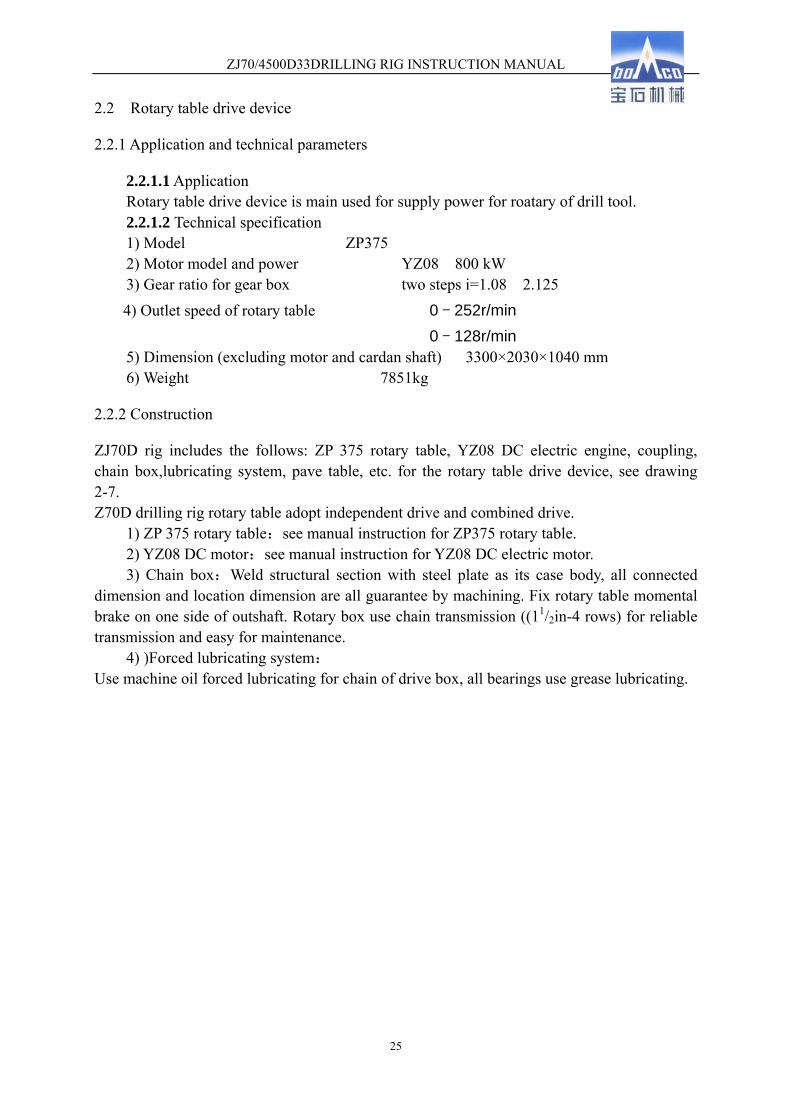
2.2.1.1 Application Rotary table drive device is main used for supply power for roatary of drill tool. 2.2.1.2 Technical specification 1) Model ZP375 2) Motor model and power YZ08 800 kW 3) Gear ratio for gear box two steps i=1.08 2.125 4) Outlet speed of rotary table 0-252r/min 0-128r/min 5) Dimension (excluding motor and cardan shaft) 3300×2030×1040 mm 6) Weight 7851kg
2.2.2 Construction
ZJ70D rig includes the follows: ZP 375 rotary table, YZ08 DC electric engine, coupling, chain box,lubricating system, pave table, etc. for the rotary table drive device, see drawing 2-7. Z70D drilling rig rotary table adopt independent drive and combined drive.
1) ZP 375 rotary table:see manual instruction for ZP375 rotary table. 2) YZ08 DC motor:see manual instruction for YZ08 DC electric motor. 3) Chain box:Weld structural section with steel plate as its case body, all connected
dimension and location dimension are all guarantee by machining. Fix rotary table momental brake on one side of outshaft. Rotary box use chain transmission ((11/2in-4 rows) for reliable transmission and easy for maintenance.
4) )Forced lubricating system: Use machine oil forced lubricating for chain of drive box, all bearings use grease lubricating.

ZJ70/4500D33DRILLING RIG INSTRUCTION MANUAL
26
Drawing 7 ZJ70D Rotary table drive device
Lubricating unit of drive device is electric lubricating system, electric lubricating system is drived oil pump by one independent electric machine to suction the lubricating oil from oil basin, lubricate all chains and bearings by charging system. Control for electric oil pump and rotary table electric machine combined together: that is when start on one of them, the lubricating oil pump will start work firstly. The electric machine of lubricating oil pump could trun on individually: that is to say, the user could start on lubricating oil pump without start on electric machine of rotary table. Install oil filter (LXZ-100×180L-Y) on the inlet pot of oil basin, it should be inspected normally so that the greasy dirt which is bulked could be cleaned in time. Fix overflow valve on the oil path. When the pressure of system is much higher, it could be used for adjust the system pressure. Install rotary table lubricating pressure gauge on the driller’s box to monitor the pressure of lubricating systm. When the pressure is in low position, it could be check by stop the machine, after the problems have been solved, it could start the job. Working pressure for lubricating system is 0.15-0.4MPa. The oil products: L-AN100 machine oil is used at temperature of 0℃--50 in summer and ℃
L-AN46 machine oil is used at temperature of –30℃--0 in winter. The oil shall be added ℃
between two graduation marks of the oil gauge.
2.2.3 ZP-375 rotary table
2.2.3.1 Technical specification Type ZP375
Diameter of opening 952.5mm Max. load static 5850kN Max. speed 300r/min

ZJ70/4500D33DRILLING RIG INSTRUCTION MANUAL
27
Gear ratio 3.56 Overall dimensions(length × width × height) 2415×1810×718mm Weight 7970kg
2.2.3.2 Structure For structure of ZP375 rotary table, please see drawing 2-8. The ZP-375 rotary table (Fig.1, 2) is mainly composed of table (8), housing (6), pinion shaft assembly (10), lock device (1), master bushing (9) and cover (7). The housing (6) is made of steel casting and welded structures. The housing can be used as oil sump for lubricating the bevel gears and bearings. The table (8-2) is a steel casting. Its opening is used for passing of drilling and casing strings. In order to rotate the drilling string, two flutes located in the table, two bulges located in the top of master bushing are put into the flutes. The bearing support (8-5) is fixed under the table with screws (8-7). The table assembly is mounted on prime-second combination bearing (8-3), it can be supported on the substructure by the center race of bearing. The top section of center race of the combination bearing is used as main bearing, it can bear the total load of the drilling and casing strings, the bottom section of center race is used as second bearing, it is mounted under the table with bearing support, it can bear the upward beating from the bottom hole. The shims (8-6) between the table and bearing support can be used to adjust the axial clearance of hold-down bearing. The table is driven by a pair of bevel gears: a ring gear(8-1) mounted at the table and a pinion(10-1) mounted at one end of the shaft(10-4) which lies on the two bearings(10-2)(10-6) located in the capsule(10-3): a radial short―roller bearing and a radial spherical―roller bearing. The other end of the shaft is provided with double sprockets (10-7) or flange (10-8) to compose pinion shaft assembly (10). The shims (8-4) under the center washer of prime and second combination bearing and the shims (10-5) on the capsule flange are used for adjusting the backlash of the bevel gears. At the top of the rotary table are mounted the lock assembly (1) to stop the rotation of the table (to the right or left). For locking the table, the left or right lock pawl (1-1) is put into one of the 28 slots by the handle (1-2). Master bushing assembly (9) is of the split type, two bulges of up section is put into the grooves of table, the master bushing can be removed out of the table by of means the two lift hooks.

ZJ70/4500D33DRILLING RIG INSTRUCTION MANUAL
28
Drawing 2-8 Outside and sectional drawing for ZP375 rotary table
2.3 TC7-450 crown block
2.3.1 Application:
Crown block is a fixed sheave group at the top of mast, it is connected with traveling block by wireline to a set of sheave system, it could reduce tensile force of fast line, in case of that, it could reduce the operating capacity of drawworks (make up and make out drill pipe, casing, drilling, hanging the drill tools) and outfitted power of engine unit.
2.3.2 Technical datas
1) Max. hook 4500kN 2) Dia. Of sheave Φ1524mm 3) Number of sheaves 7 4) Dia. Of wireline Φ38mm
至转盘中心1478

ZJ70/4500D33DRILLING RIG INSTRUCTION MANUAL
29
5) Dia. Of sand wheel Φ762mm 6)Dia. of sand wireline Φ14.5mm 7) Dia of auxiliary sheave Φ400mm 8)Overall dimension 3407mm×2722mm×2858mm 9) Weight 11000 kg
2.3.3 Substructure
For TC7-450 crown block substructure, see attached drawing 2-9.
Drawing 2-9 TC7-450 Crown Block
1-rail;2-main sheave assy.;3-guide sheave assy.;4-crwon block crane boom;5-sand sheave assy.;6-auxiliary sheave;7-crown block frame
TC7-450 crown block is consists of crown block frame, guide wheel assembly, master pulley block, railings, etc, it also matched with crown block crane boom, one sand sheave, four auxiliary sheaves and anti-clash beam (pine wood).
1) Crown block frame: Weld integrally structure, connect top section with main sheave
axle seat, guide sheave axle seat and sand sheave axle seat individually by bolts, fit the
bottom section to mast by bolts.
2) Guide sheave assembly: It including the following parts: wheel shaft, support, sheaves,
bearings and so on. In order to convenience for filling-up lubricating grease to bearings, fit a
M10 x 1 grease fitting on the shaft end.
3) Main sheave assembly: It consists of main shaft, support, six sheaves, bearings, etc.
Fix a set of bearings to each sheave, at the end of shaft, fix a M10 x 1 grease fitting for
filling-up lubricating grease to the sheave.
4) Crown block crane boom: It used for maintenance crown block, it is a simple

ZJ70/4500D33DRILLING RIG INSTRUCTION MANUAL
30
cantilever crane with max. hoisting weight 49kN (5tf). 5) Auxiliary sheave: It could individual used for hoist heavy, drill pipe and hoisting
hydro pneumatic of two pneumatic drawworks, with 30kN (3tf) load capacity for each sheave. Place wireline rod for all of the sheaves external to protect sheaves and ensure the
wireline could not jump from grooves.
2.4 YC-450 Travelling block
2.4.1 Technical specification
1) Model YC-450 2) Max. Static load rating 4500kN (500tons) 3) Number of sheaves 6 4) O.D of the sheaves Φ1524mm (60″) 5) Diameter of wireline 38mm(11/2″)、34.5mm(13/8″) 6) Overall dimension (length x width x height) 3110×1600×840 (mm) 7) Theoretical weitht 8740kg (19269lb)
Drawing 2-10 YC-450 Travelling Block 1- cap;2- stud;3- left housing assy.;4- hanging beam pin;5- safety guard pin;6-
sheave;7- shaft;8- right housing assy.;9- clevis;10- clevis pin
2.4.2 Structure
For YC 450 travelling block, please see drawing 2-10.
ZJ70/4500D33DRILLING RIG INSTRUCTION MANUAL
31
The sheaves are supported on the shaft with double-row conicalroller bearings. Each bearing has its lubrication channel and can be individually lubricated with grease fittings located at the ends of the shaft. The sheave grooves are machined according to API specification. The travelling block is equipped with two sizes of grooves with 38mm (1 1/2”) and 34.5 (1 3/8”) wirelines according to the customer’s requirements. Both of them are casehardened to minimize wearing. The upper parts of the housing assemblies are connected with the cap (1) by the stud (2). The clevis (9) is securely fastened to the two housing assemblies with the two clevis pins(10). One end of each clevis pin is fixed with slotted nut and cotter pin. The hook can be removed from and reattached to the travelling block with either of clevis pins or both removed.
2.5 DG-450 Hook
2.5.1 Technical specification
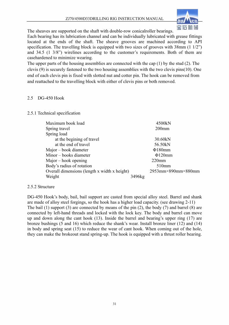
Maximum book load 4500kN Spring travel 200mm Spring load
at the begining of travel 30.60kN at the end of travel 56.50kN
Major – book diameter Φ180mm Minor – books diameter Φ120mm Major – hook opening 220mm Body’s radius of rotation 510mm Overall dimensions (length x width x height) 2953mm×890mm×880mm Weight 3496kg
2.5.2 Structure
DG-450 Hook’s body, bail, bail support are casted from special alloy steel. Barrel and shank are made of alloy steel forgings, so the hook has a higher load capacity. (see drawing 2-11) The bail (1) support (3) are connected by means of the pin (2), the body (7) and barrel (8) are connected by left-hand threads and locked with the lock key. The body and barrel can move up and down along the cant hook (13). Inside the barrel and bearing’s upper ring (17) are bronze bushings (5 and 16) which reduce the shank’s wear. Install bronze liner (12) and (14) in body and spring seat (15) to reduce the wear of cant hook. When coming out of the hole, they can make the brokeout stand spring-up. The hook is equipped with a thrust roller bearing.

ZJ70/4500D33DRILLING RIG INSTRUCTION MANUAL
32
Drawing 2-11 DG450 hook
DG-450 hook is designed and manufactured strictly according to API SPEC 8A. After the hook is assembled, the chamber in body and barrel is divided into two parts by bearing’s upper ring, which is provided with liquid path. After the barrel is filled with machine oil, the hook is provided with a hydraulic snubber, which can eliminate the bounce vibration of the drilling pipes when breaking out the stand to prevent the damage to the tool joint threads. The machine oil aslo has a function of lubricating the bearing (16), lock assembly (17) and other parts. At the upper end of the barnel is mounted a safety and positioning device, which consists of 6 springs and positioner (4). When hoisting the empty elevator, the positioner is in contact with the annular surface of the bail support, and by way of friction of contact surfaces to prevents the rotatio of the body thus keeping the empty elevator in the correct orientation for the convenience of the derrickman operation. When suspending the drill string, the positioner is separated from the bail support, the body can be rotated at either direction and the travelling block is in no way rotated.
2.6 SL-450 Swivel
2.6.1 Use & Scope of Applications
1) Hang up the drill pipe;
2) As a connect part between lifting parts (non-rotary) with rotary drill tools;
3) As a through way for input the high pressure mud;
4) As a spinner. When drilling, it use joint stand or take out Kelly. 5) SL450 swivel is applicable for 5000m-7000m drilling rig.
工作行程
ZJ70/4500D33DRILLING RIG INSTRUCTION MANUAL
33
2.6.2 Technical data
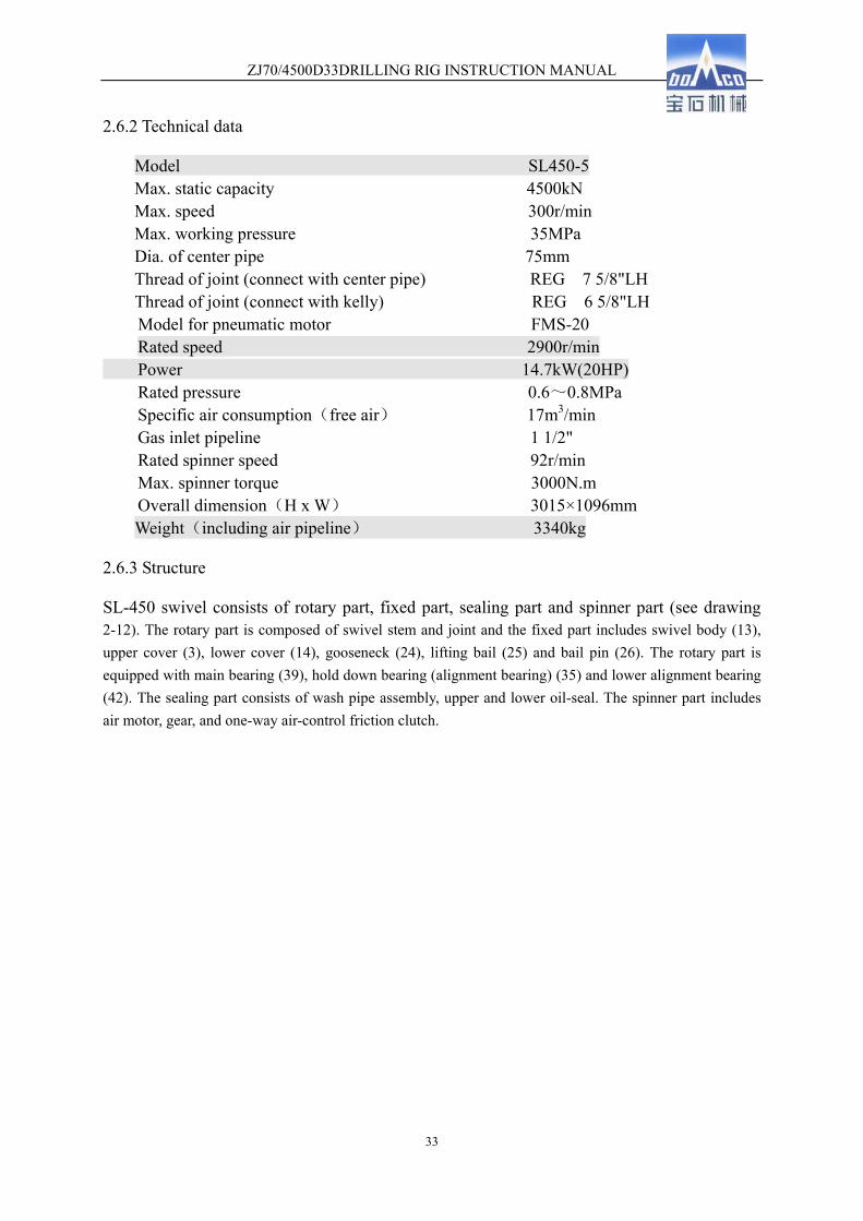
Model SL450-5 Max. static capacity 4500kN Max. speed 300r/min Max. working pressure 35MPa Dia. of center pipe 75mm Thread of joint (connect with center pipe) REG 7 5/8"LH Thread of joint (connect with kelly) REG 6 5/8"LH
Model for pneumatic motor FMS-20 Rated speed 2900r/min Power 14.7kW(20HP)
Rated pressure 0.6~0.8MPa Specific air consumption(free air) 17m3/min Gas inlet pipeline 1 1/2" Rated spinner speed 92r/min Max. spinner torque 3000N.m Overall dimension(H x W) 3015×1096mm
Weight(including air pipeline) 3340kg
2.6.3 Structure
SL-450 swivel consists of rotary part, fixed part, sealing part and spinner part (see drawing 2-12). The rotary part is composed of swivel stem and joint and the fixed part includes swivel body (13), upper cover (3), lower cover (14), gooseneck (24), lifting bail (25) and bail pin (26). The rotary part is equipped with main bearing (39), hold down bearing (alignment bearing) (35) and lower alignment bearing (42). The sealing part consists of wash pipe assembly, upper and lower oil-seal. The spinner part includes air motor, gear, and one-way air-control friction clutch.

ZJ70/4500D33DRILLING RIG INSTRUCTION MANUAL
34
drawing 2-12 SL450 swivel (front view)
向

ZJ70/4500D33DRILLING RIG INSTRUCTION MANUAL
35
drawing 2-12 SL450 swivel (top view) The swivel stem supports the whole weight of the drill string and the mud pressure. The joint thread between the stem and connector and the one between the connector and Kelly are conform to the thread size and measure means of API Spec 7 (The instruction manual for rotary drill string components). The stem is a through hole part. It is connected with wash pipe assembly at the upper side and joint at the lower side. The stem is fixed by main bearing at the center portion and alignment bearings at the two sides. The upper alignment bearing can avoid moving upward of stem. There is a rubber umbrella (5) at the upper side of stem to prevent from entering the swivel body of mud. Besides, there is O sealing ring (46) between stem and joint to avoid washing out the thread and function sealing. The lifting bail is connected with shell with two pins and hangs the swivel on the hook. The shell is not only a load-bearing part and but also an oil pool to lubricate and cool the main bearing and alignment bearing. It is connected with upper cover at the upper side and lower cover at lower side and is equipped with bumper to avoid impacting with elevator links during the drilling job. There are an alignment bearing and two skeleton type oil seal (33) in the upper cover. The two skeleton type oil seal is fixed in reverse directions to avoid leaking of oil in the shell and entering of mud. Besides, there is a tap hole to fill oil into the shell and fix the oil scale (28). The oil plug of oil scale has a 90°continues hole to as air-out. The gooseneck, fixed on the flange of upper cover, has a taper thread hole for well logging. During the drilling job, the hole is plugged with a pipe plug (1) to avoid the releasing of high-pressure mud. The gooseneck is connected with wash pipe assembly (4) in one side and with hose by inner joint in another side (the inner pipeline thread of inner joint is measuring to the API std 5B). There are lower alignment bearing (42) and three skeleton type oil seal in
29 3026
C向
1085
1090
31
2 31 32
28
3231

ZJ70/4500D33DRILLING RIG INSTRUCTION MANUAL
36
lower section to seal the oil in the swivel.
drawing 2-13 wash pipe assy. 1、upper packing box gland 2、upper packing box 3、spring ring 4、upper seal gasket 5、mud packing 6、upper bushing ring 7、wash pipe 8、lower packing box 9、lower bushing ring 10、Seal ring 11、Seal ring 12、lower seal gasket 13、lower packing box gland 14、O-ring 15、oil cup M10 x 1 16、locking nut M10 x 12 17、O-ring The wash pipe assembly (drawing 2-13) is connected with gooseneck and stem. These three parts act as the entryway of mud. The wash pipe assembly adopting the self-sealing and quick-assembly structure is the important part to seal the high-pressure mud. When replacing the wash pipe and packing set, open the upper and lower packing box to carry out the whole part, the gooseneck and hose need not disassembling. It is very simple and convenient that can replace the washing pipe and packing set at any moment during the drilling job.
2.6.4 Drive principle for spinner power
For the power drive principle for spinner, see drawing 2-14.
Drawing 2-14 power schematic plan for spinner
1、gas motor 2、small gear m=3,Z=16 3、large gear m=3,Z=53 4、wearing plate cluch 5、gear shaft m=5,Z=12 6、large gear ring m=5,Z=110 7、center pipe
By the rotation of gas motor, to drive secondary change-speed of two pairs of gear wheels, and then transmit torque to center pipe for connect single or screw out Kelly.

ZJ70/4500D33DRILLING RIG INSTRUCTION MANUAL
37
2.7 JJ450/45-K14 Mast
2.7.1 Application
JJ450/45-K14 mast is used to mount the crown block, hang the traveling system and rack up the drill pipe.
2.7.2 Technical parameters
1) Max. hook load (6x7 line strung, no wind load, no drill pipe stands against monkey board) 4500kN
(Note: acceleration, impact, wind load and racking stands will lower the maximum hook load, see the mast nameplate.)
2) Effective height 45.5m 3) Top opening (front/side) 2.5/2.2m 4) Bottom opening 10m 5) Monkey board height 24.5;25.5;26.5m 6) Setback capacity (4 1/2" drill pipe、28m stand) 7000m
9 1/2" drill collar 4 pole、8" drill collar 4 pole 7) Wind speed
Waiting on weather (no hook load, full stands against monkey board) 36m/s ·Survival (no hook load, no stands against monkey board) 47.8m/s Raising and lowering mast ≤8.3m/s
8) Theoretical weight 105000Kg
2.7.3 Structure
Structure for JJ450/45-K mast, please see drawing 2-16. 1) Mast body is front-opened type, it has four sections and eight parts, oblique draw rod,
which is at the back of mast, and beam are connected with main body, all parts of body are fitted together by use pins. Casing board, standpipe board, resting board and so on are matched with mast, meanwhile, match with ladder and lading-help system through to monkey board and crown block board. In order to meet the drilling requirement, it also match with two high hoist cathead sheaves with 3t hoisting capacity, deadline stabilizer, two sets of suspended derrick mast with 2.5t hoisting capacity and 270ºswing, tong counterbalance and sheaves.
2) Install mast support on the drill floor, mast will be raised and lowered integrality through gin pole by the drawworks power; After mast is raised, align the front, back, left and right of well by increase or reduce the gaskets of mast support, design the position for install jack;
3) Gin pole is a kind of door structure, which consists of left and right front legs, left and right back legs and beam, etc, it is used for rising and lowering and placing mast. Fix installation base plate of fast line guide.
4) 4) Put two high hoisting cathead sheave with 2.5t capacity on the second back beam under the top of mast, space length between two sheaves is 1500mm; 5) Install ladder at the left side of mast which will enter to the crown block table, install

ZJ70/4500D33DRILLING RIG INSTRUCTION MANUAL
38
double ladder safety climb equipment, install ladder at the right side of mast which will enter to the monkey board;
6) Fix monkey board (it includes one pneumatic winch with 0.5t and pneumatic pipelines), mount it in the middle position, fix guide sheave at the left and right side, install anti-wind wall at the three sides of monkey board, fix escape equipment; Design the position on monkey board which could be tied the safety chain for driller. 7) Fit double standpipe derrick, deadline anchor, fastline guide and two hoisting derrick with capacity 2.5t (it could be rotate 270°) and electric telescopic casing stabbing board; 8) Fit with B-type tong balance weight, hydraulic tong guide chain, sheave, basement and wireline; 9) Install deadline anchor at the inner side of right leg of mast, the installation height for deadline anchor could meet the requirement for reverse wireline on drill floor. All parts for mast (nuts, lamps and pins) are all fit with anti-clash equipment, install safety chain on crown block and auxiliary sheave of mast, it meet the requirement of HSE; 10) After raise the mast, hang the raise wireline on the wireline hoister of the inner side of mast; 11) Design the installation position for reaction torque of top drive unit of mast. 12) Raise equipment JJ450/45-K14 mast is raised by gin pole. Fix with high and low support, raise wireline and tripod of raise equipment. Install hydraulic buffer unit to realize place the mast on the gin pole steadly and to forward the gravity center of mast so that mast could be lowered by its own deadweight, all these actions will be realized by telescopic of cylinder. For the drawing of raising, please see drawing 2-15.
Drawing 2-15 Raise for Mast 1- High support;2- Lower support;3- Raise wireline;4-support frame;5- Tripod;6-hook

ZJ70/4500D33DRILLING RIG INSTRUCTION MANUAL
39
Drawing 2-16 JJ450/45-K14 mast
1- ladder safety climb equipment;2-left upper section;3-right upper section;4-left middle-upper section; 5-right middle-upper section;6-monkey board;7-tong balance
钻台面

ZJ70/4500D33DRILLING RIG INSTRUCTION MANUAL
40
weight;8-ladder;9-left middle-bottom section;10-right middle-bottom section;11-casing board;12-left bottom section;13-right bottom section;14-driller’s board;15-gin pole;16-rasing equipment;17-dead line anchor;18-escape equipment
2.8 DZ450/10.5-X Substructure
DZ450/10.5-X substructure that is a component matched for ZJ70D drilling rig, it is used to mount mast, drawworks, rotary table, stands and drill tools, therefore, it is an important site for the drilling operation.
2.8.1 Basic Technical Parameters
1) Drill floor height 10.5m 2) Drill floor area 13.935m×13m 3) Height of rotary beam bottom 9m 4) Distance from wellhead center line to drum center line 4.86m 5) Max. rotary be Rated setback capacity (4 1/2" drill pipe、28 m stands) 7000m 7) Max. combination of maximum rotary beam load and rated setback loa: (1) Max. rotary beam load 4500kN (2) Rated setback load 2200kN 8) Drilling rig model ZJ70D
9) Mast model JJ450/45-K14
10) Rotary table model ZP-375 11) Theoretical net weight 167800kg
2.8.2 Description on structure
DZ450/10.5-X swing up type substructure consists of upper and lower bases, front and rear upright posts, A frame gin pole, setback area, drawworks beam and rotary beam. It has the following features:
1) The movement principle of the parallelogram mechanism is used in the substructure design, so that the equipment on the raised drill floor may be assembled on the ground. 2) Using the drawworks power enables the substructure to be raised integrally from the low position to the working position by means of the hook and wirelines strung. (see drawing 2-17) 3) The substructure and mast use the same drilling line.
4) The stabilizer of mast locate on the base of substructure which can increase the stability . 5) According to the raised drill floor features, the substructure is furnished with a safety slide, whereby drilling workers can escape from the drill floor rapidly once an accident occurs during the drilling.
6) Besides, the substructure is furnished with a hydraulic lift, whereby drilling workers and light-duty drill tools can be raised or lowered from or to the drill floor.
7) A wellhead hoisting device is furnished under the rotary beam to facilitate the installation of wellhead equipment.

ZJ70/4500D33DRILLING RIG INSTRUCTION MANUAL
41
8) The substructure uses the construction of high platform and large space.
For the detail of DZ450/10.5-X substructure, please see its manual instruction.
Drawing 2-17 general drawing for substructure
2.9 Air System
The air system of ZJ70/4500D33 consists of air supply of compressed air, air treatment system, air control component, air pipeline and is used to control the switch, shift, brake and spacing, etc.
2.9.1 Technical Parameter
1) Electric Screw Air Compressor Sets Model LS12-50HHAC Air Displacement 5.5m3/min Displaced Air Pressure 1MPa Cooling Mode Wind-cooling
10500
1650
4 50 68 009 50
4 43 01 21 80
1 85 00
2 340 23 407 660
13 93 510 00 0
4 43 0 4 86 0
200
800
12 00
2300
φ300
φ350
165
0
10 00 0
100
00
13000
667
5

ZJ70/4500D33DRILLING RIG INSTRUCTION MANUAL
42
Motor Model 50HP/380V
2)System Working Pressure 0.9MPa 3)Drier Type oilfield special-purpose high-temp freeze dryer 4)Suitable Ambient Temperature -40℃~60℃ 5)Rated Dew Point 5℃ 6)Oil Content of Product Air ≤5mg/m3 7)Dust Content of Product Air ≤5mg/m3 8) Model of cold-starting air compressor W-0.8/12
(Displacement: 0.8 m3/min, Driven by diesel engine) 9) Air tank capacity 2.5 m3+4m3 (on the substructure) 10) Air winch 1) 5t air winch
Model XJFH5/35 Rated hoisting capacity 5T Max. rope speed 35m/min Max. hoisting capacity 5.5t Rated power 16kW Air-in pressure 0.6-0.9MPa Rated air consumption 12.7m3/min Rope capacity ratings 200m Wire rope diameter �20mm
1) 0.5 t air winch Model TJC-5A Rated hoisting capacity 0.5T Max. rope speed 12m/min Rated power 16kW Air-in pressure 0.6-0.9MPa Rope capacity ratings 120m Wire rope diameter �8mm Diameter of wind pipe �25mm
2.9.2 Air System Flow
See Fig. 2-19 for ZJ70D drilling rig air system flow. Two electric screw compounded through check valves and one IW-0.6/12 cold-starting compressors to supply compressed air. When in normal use, one compressor works while another is stand-by or two compressors work alternatively or simultaneously. The cold-starting compressors is manual or electrical start. Its main function is to store some compressed air to air tank to start diesel engine or as a emergency stand-by compressor before there is no power and the rig has been assembled. After processed by the freeze dryer, the compressed air enters 2.5m3 air tank. The air tank has two outlets, the upper outlet conveys the compressed air into the pneumatic motor to drive the diesel through the air pipeline; the lateral outlet conveys the compressed air into all equipment

ZJ70/4500D33DRILLING RIG INSTRUCTION MANUAL
43
that use the air through the air pipeline. The air stored in 4m3 air tank on the substructure, which is air to air-driven equipment, 0.7 to 0.9Mpa, is mainly supplied to drawworks, spinner, pneumatic winch and pneumatic tong.

ZJ70/4500D33DRILLING RIG INSTRUCTION MANUAL
44
Pneu
mat
ic S
pann
erSa
nd R
eel
C
lutc
hC
row
n Bl
ock
Save
r
Rel
ease
Rota
ry T
able
.N
eutr
al B
rake
Air
Pres
sure
Gau
ge
Dro
ww
ork
Hi/L
o
Gau
ge o
f C
BS
3-po
sitio
nC
ylin
der Cyl
inde
r
3-Po
sitio
n Cy
linde
r
Shi
ftin
g Val
ve
Oil
Pres
sure
Gag
ue
Cath
ead
Cont
rolle
r
Shift
ing
Valv
e
Pres
sure
Gau
ge
of
Sh
ift-lo
ck
Ball
Valv
e
Filte
r
Hor
n P
ush
bot
ton
Hor
n
Fig. 2-19 Air System Principle

ZJ70/4500D33DRILLING RIG INSTRUCTION MANUAL
45
2.9.3 Air Supply And Air Treatment System
2.9.3.1 The air supply purifying device consists of two sets LS12-50HHAC electric screw air compressor, one set of cold starting air compressor unit, one set of freeze dryer and one 2.5m3 air tank. (See Fig. 2-20)
Connecte To The4m Air Tank UnderDrilling Floor
Connecte To Air StartMotor of 4 Diesels
3
Air Tank
Air Dryer
Com
pres
sor
Star
ted
Wit
hou
t El
ectr
ic P
ower
Com
pres
sor
Com
pres
sor
Fig.2-20 Air Purifying Principle 2.9.3.2 The air supply system mainly consists of two screw compressors, type LS12-50HHAC, wind cooling and their outlet pressure 1.0Mpa. One compressor works while another is stand-by or two compressors work alternatively or simultaneously. See “Instruction manual for Air Supply And Air Treatment System” At the beginning of rig assembly, the cold starting compressor unit is for start the diesel generator set. The compressor unit is equipped with a air compressor head of W-0.6/12 and a manual/electrical starting diesel engine of YAMAHA S195as prime motor. Main technical specifications of the motor: W type, air-cooling, single-acting piston, two-stage compressor, exhaust pressure rating: 1.2Mpa, nominal capacity flow: 0.6m3/min, travel of piston: 80mm, lubrication: N100# in summer N68# in winter (the oil should be replaced after running 500 hours), oil consumption: ≤16g/h, O.D. (L x W x H): 1650x530x860mm. 2.9.3.3 The freeze dryer is for removing the water of compressed air. The temperature of compressed air can be lowered to dew-point temperature 2 by the air ℃
heat-exchanging apparatus and the moisture or water drop of compressed air can be

ZJ70/4500D33DRILLING RIG INSTRUCTION MANUAL
46
curdled. Then the air and water drop is separated by the separator and water drop is discharged out by the automatic drainer. Under the normal conditions, the moisture content of dried compressed air is 0.59g/m3, the water removal ratio is 93%. 1) Compressed Air Flow:
The moist and high-heat compressed air enters the system by the inlet of dryer. Firstly, the temperature of air can be lowered to room temperature by the front air cooler (G TYPE special tool) and be lowered a little by the air heat-exchanging apparatus to remove some water drop of air. Secondly, it is lowered to dew-point temperature 2℃ by the coolant boiler to remove the majority of water drop of air. Thirdly, the air and water drop is separated by the cyclone separator and the water drop is discharged out by the automatic drainer. Finally, the dried air is heating-up a little by the air heat-exchanging apparatus and reach the outlet to avoid the rustiness of air pipeline and save energy. 2) Coolant System Flow: The coolant becomes the high-temp and high-pressure air through the coolant compressor. The coolant is heat exchanging with return low-temp coolant to lower the temperature and becomes the fluid coolant through the cooler. The desiccant is mainly for drying and filtering the water and impurity of coolant pipeline. The operator can monitor the volume and drying level of coolant by its visual window. After the high-pressure fluid coolant is expanded, it becomes the low-pressure air and enters the boiler to absorb the heat of compressed air and lower its temperature, finally make the water curdling as water drop. The by-pass valve of heat air can adjust the wind rate at any time and load of coolant compressing. Finally, the coolant reaches the inlet of compressor through the low-pressure fluid storer or coolant heat-exchanging apparatus and becomes the coolant return after compressed.

ZJ70/4500D33DRILLING RIG INSTRUCTION MANUAL
47
Fig.2-21 Freeze Drier System Flow Chart
1 Coolant compressor 2 Coolant heat exchanger 3 Air-cooling cooler 4 Water-cooling cooler 5 Repairing valve 6 Charge valve 7 Dryness filter 8 Electromagnetic valve 9 Coolant visual window 10 Expand valve 11 Exchanger pipe 12 Hot air bypass valve 13 Evaporator 14 Air water separator 15 Air exchanger 16 Liquid air separator 17 Air cooling front cooler 18 Water cooling front cooler 19 High pressure shut–off switch 20 Pressure control switch 21 Automatic water drainer 22 Cooling water filter 23 Constant pressure water supply valve 24 High pressure relief valve 25 Air inlet pressure gauge 26 Air outlet pressure gauge 27 Pressure gauge of coolant suction 28 High pressure gauge of coolant 2.9.4 Air Supply Pipeline For Diesel Generator Sets See Fig.2-22 for 2.5m3 air tank.

ZJ70/4500D33DRILLING RIG INSTRUCTION MANUAL
48
Fig. 2-22 Air Tank Structure
1. Support base 2. Drain Joint G 1” 3. Air-inlet connection tube φ57×5 4. Main body 5. Pressure gauge joint M33×2 6 . Nameplate 7. Nameplate base 8. Nail for nameplate φ3×6 9.Syphon φ57×3.5 10. Safety joint G 1 1/2 ” 11. Vent-pipe joint φ57×5 12. Upper and lower end plate
The air from the upper outlet of 2.5m3 air tank conveys into 4 pneumatic motors respectively, the main hard pipe is laid along the roof, the hose is connected between houses. All air supply pipelines for diesels are fitted with globe valves. Before diesels are driven, open globe valves to supply the air.
ZJ70/4500D33DRILLING RIG INSTRUCTION MANUAL
49
2.9.5 4m3 Air Tank
4m3 air tank mounted at the rear part of the substructure is equipped with air inlet, alcohol funnel, safety valve, pressure gauge, sewage outlet and stand-by air outlet. When in normal use, open two air outlets at left and right, when in temporary use, open the stand-by air outlet, each air outlet is fitted with a valve, open the valve to supply the air. Air supply pipeline from 2.5m3 air tank of the source air-purifying device is connected to air tank through the air pipeline in the folded pipeline channel.
2.9.6 Crown Block Saver
There are three kind of safety devices. One is overwind anti-collision valve mounted on drawworks, another is wireline anti-collision switch and the third one is traveling block position digital display. For overwind valve, see its structure and principle in the Drawworks section. The wireline ring and the guide sheave have been welded together. Before using, the wireline is laid along the guide sheave and connected to the air control valve. When the traveling block-hook-elevator link system is raised to the limit position (6.5m safety height from the crown beam bottom), the wireline on the mast is collided to make another end of the wireline to be raised, by this time, the linen rope connected to the wireline on 2-HA-1 anti-collision switch handle is broken, the switch handle lowers to the “open” position under the action of heavy hammer, one route of control air enter into hydraulic disk brake to brake and the other route cut off 3/2ND12 (normal open two-position three-way valve) to make the drum high speed and low speed clutch exhaust thereby stop the traveling system.
2.10 Drilling Instrumentation
2.10.1 Main Functions
To monitor hook load, bit weight, rotary speed , rotary torque, tongs torque, standpipe pressure of three mud pumps, mud return flow of wellhead, well depth and capacity and parameters of mud pit (including the mud tripping tank) and warn when the parameter is abnormal. All sensor, display console, connector, DAQ system is essential safety type. The display console is rustless steel and is fixed in the driller cabin. The sensors are fixed at the relative positions and DAQ is fixed in the driller house. The industrial computer, fixed in the drilling engineer room, is for recording and storing the parameters. Main functions of industrial computer: real-time record the drilling parameters in the means of number and curve; store and print and parameters; display and print the former parameters. Display the drilling speed, hook position, cumulative strokes of pump, total pump speed, ton/km of wire line on the computer.

ZJ70/4500D33DRILLING RIG INSTRUCTION MANUAL
50
See drilling instrumentation manual for details.
2.11 Mechanized Wellhead Tools
2.11.1 Function
Mechanized wellhead tools are mainly used to make up and break out pipe threads during connecting drill pipe, tripping in and out and running casing operation. These tools are controlled by hydraulic pressure or air, greatly reducing the manual labor intensity, saving the drilling time and promoting the drilling efficiency. The drilling rig is equipped with drill pipe power tong, hydraulic casing tong, make-up and break out hydraulic catheads and hydraulic power station supplying the hydraulic power to tools.
2.11.2 Technical Parameter
1) Hydraulic power station (YZ630T) Rated flow 115L/min Rated working pressure 16MPa Effective capacity of oil tank 630L Motor power 37 kW
2) Drill pipe power tong (ZQ100) Suitable pipe diameter 3-1/2~8 in Max. Torque 100kN.m Tong jaw speed high-speed gear 40rpm Low speed gear 2.73rpm Working pressure of hydraulic system 16.6MPa Rated flow of hydraulic system 114L/min Working pressure of pneumatic system 0.9 MPa Tong head moving distance 1.5 m Overall dimensions 1700x1000x1400mm Weight 2400 kg 3) Hydraulic casing tong (TQ-35) Suitable size range 4~13-3/8 in Rated working pressure 16MPa Rated flow 160L/min
Tong head speed high speed gear 50~80rpm Low speed gear 6-14rpm Max. Torque high speed gear 3.7 kN.m Low speed gear 7~12kN.m Overall dimensions 1520mmx850mmx670mm Weight 560 kg
4) Hydraulic Cat Head YM-16 YM16

ZJ70/4500D33DRILLING RIG INSTRUCTION MANUAL
51
Rated working pressure 16MPa 16MPa Rated flow 120L/min 120L/min Nominal pulling travel 1500mm 1500mm Rated pulling force 160kN 160kN Size of wire line GB1102-74 multi-layer non-revolution
wireline 18×7-27-170-I
2.12 F-1600 Mud Pump Unitizations
2.12.1 Function
F-1600 mud pump unitization driven by DC motor through narrow V-belts is used to pump the high pressure mud to the well bottom so as to jet and break the stone, cool the bit and carry the cuttings out.
2.12.2 Technical Parameter
1)V-belt model: 2×4ZV25J+1×5ZV25J Length: 7620mm
2) Sheave diameter Φ536.5/Φ1165mm 3)Mud pump model: F-1600 horizontal triplex single action pump
Rated power 1180kW Max. liner diameter Φ180mm Max. pressure 34.4MPa Rated stroke per minute 120r/min Stroke length 305mm Suction inlet diameter 12" flange Discharge outlet diameter 5" flange Weight 24791kg
2.12.3 Instruction to Structure
F-1600 mud pump unitization consists of mud pump, narrow V-belts, DC motor, base, guard, safety valve, pressure-releasing pipeline electric spraying system, etc. Two DC motor drive one mud pump through 2x4ZV25J+1x5ZV25J narrow V-belts individually. DC motor base may be adjusted on the pump base to tighten V-belts up. A steerable cantilever hoist is equipped for maintenance of pump purpose. When assembling, adjust the outer end face of the large belt according to the outer end face of the small sheave, the planeness shall be ≦1mm.
The pump unitization is equipped with totally-closed belt guard and rain shelter of motor.

ZJ70/4500D33DRILLING RIG INSTRUCTION MANUAL
52
2.13 High Pressure Manifolds
2.13.1 Function
The high pressure manifold is one of main equipment for the high pressure jet drilling operation. The function of manifold is to convey the high pressure mud discharged from the mud pump into the drill pipe by controlling the high pressure valve set, the mud is jetted out of the bit to produce the jet flow of the high pressure mud, thus realizing the high pressure jet drilling, emptying and charging mud, promoting the drilling speed and cutting the drilling cost.
2.13.2 Technical Parameter
1) Nominal opening 101mm 2) Max. working pressure 35MPa 3) Pressure under strength test 52.5MPa 4) Suitable temperature -40℃~+121℃ 5) Suitable medium clear water, mud, crude oil and fracture fluid
6) Connection method union 7) Gate driving method manually operation detailed information please its manual instruction.
2.14 Power System
ZJ70D drilling rig system is consists of primary diesel generator sets, auxiliary diesel generator sets and generator houses, etc.
2.14.1 Technical Parameter:
1) Qty. of primary diesel generators Four sets 2) Diesel model CAT3512 3) Diesel power and rotary speed 1080BkW/1900BKW ,
1500rpm 4) Generator model SR4/SR4B 5) Generator sets capacity 1500kVA 6) Generator voltage, frequency and
power factor 600V、50Hz、0.7
7) Qty. and power of auxiliary diesel generator
1 set 365kW,CAT3406

ZJ70/4500D33DRILLING RIG INSTRUCTION MANUAL
53
8) Auxiliary diesel generator voltage and frequency
400V/230V、50Hz
9) DC motor qty. and model 9 sets,YZ08,YZ08A 10) Rated power of DC motor 800kW
2.14.2 Primary Diesel Generator Sets:
It includes 4 sets Cat 3512 diesel generator fixed in the generator houses. According to the actual needs, SCR can control any one set or several sets generator running to distribute the power load evenly. Thus the voltage is normal and stable. Details see the Operation Manual of Cat 3512 Generator Set.
2.14.3 Auxiliary Diesel Generator Sets:
It consists of diesel engine, generator, base, electric system, control system, cooling system, exhaust air system with an integral structure and is mounted in one house independently. It can supply long-term excellent and steady AC power without watching under remote control. Details see the Operation & Maintenance Manual of CAT3406 Diesel Generator Set
2.14.4 DC Motor
Nine sets of YZ08/YZ08A DC motors equip this drilling rig. 1) The AC motors conforms to IEEE standard. Service environment : Temperature:-40℃-55℃ Humidity: relative humility ≤90% under +20℃ Desert and sand storm, etc.
2) Technical Parameter Motor model: YZ08、YZ08A Rated power: 800kW Rated voltage: 750V Rated current: 1150A Rated speed: 970r/min Max. efficiency: 92.7% Max. speed: 1500r/min Excitor type: series excitation Insulation level: (stator/rotor)H/H Draft type: forced air circulation Direction of positive rotation: clockwise Weight: 3200kg
3) Temperature rise limit
ZJ70/4500D33DRILLING RIG INSTRUCTION MANUAL
54
Component of motor
Measuring method Temp rise limit (k)
Armature copper Electricity-resistivity method 160 Main pole winding Electricity-resistivity method 180 Minus pole winding Electricity-resistivity method 180 Commutator Thermometer method 120 Bearing Thermometer method 55
4) Electric brush: Dimension: 19.1×57.2×70(mm) Limited length worn: 39.5(mm) Code: GE-T900 Brush pressure: 40±4N 5) Structure Parameter Qty of commutator copper segments: 184 Outside diameter of commutator: ø422mm Commutator length: 185mm Qty of armature core slots: 46 Form of armature winding: simplex First pitch of armature winding: 1-12 Commutator pitch: 1-2 Qty of equalizers: 92 Equalizer pitch: 1-93 6) Resistance of winding Main pole winding (15℃): 0.00535Ω Commutating winding (15℃): 0.004891Ω Armature winding (15℃): 0.00864Ω(1-47) 7) Instruction to Structure
YZ08 and YZ08A are completely same except that outlet box positions are different. YZ08 motor terminals come from right and YZ08A motor terminals come out from left watching from drive side. YZ08 and YZ08A DC motor are 4 poles series machines adopted forced ventilation, used for driving rotary table of drilling equipments, anchor windlass and mud pump. Magnetic frame is a press-formed welded fabrication. It is not only a part of magnetic path but also a main constructive component of the motor. There are two big and one small inspection windows at the commutator end to replace brushes and maintain commutator and brush holder system. When the motor is running, these inspection windows are sealed with covers. The motor has a blower in its self and the air comes in from commutator end and goes out from drive end. The model of blower is YB1160M1-2. Between commutator end and terminal box, explosion-proof flexible tube is installed to conduct high pressure air from motor inside into terminal box and keep terminal box in plus pressure. There is a pressure switch installed in the terminal box, when the blower happens to
ZJ70/4500D33DRILLING RIG INSTRUCTION MANUAL
55
breakdown, motor will stop automatically. There is an auxiliary switch installed beside the outlet box for emergency. There is a 220V, 200W single-phase heater installed in the bottom of the commutator end. When the motor stops, turn on power to prevent the motor from wetting. There is two G 3/8 screw plugs installed in the bottom of the commutators end. When there is water inside the power, open the screw plug and drain the water away.
2.14.5 Generator Sets House
It consists of 4 sets main generator set houses and 1 set auxiliary generator set house. 4 sets main CAT3512 generator sets are fixed in the 4 houses. The 300kW diesel generator set is fixed in the house No.4. There are 2 sets screw rod compressor, freeze dryer in the house No. 3. There are 2.5m3 air tank and cold-starting compressor in the house No.2. Five sets generator set houses form an inclosed space at the site. There are rain shelves between the houses. The power cable is at the upper of houses and enters into the SCR house by the cable channel. There are explosive-proof and anti-shock fluorescent lamp, emergency lamp, warning device and distribution box. 1) Main Components & Features:
It consists of base, upright post, roof, flexible door, sliding door, split door, discharge flue, pipeline of air path, pipeline of fuel oil, pipeline of lubrication, distribution & lighting system. cable channel, hanging ladder, operating floor, etc.
For convenient assembly and maintenance, the upright and base, roof is connected by bolts.
There is drain under the base. There are tap hole for grounding cable and socket for hanging ladder at the water tank side of set.
There are orifices for discharge flue and watering at the roof. The orifice for watering is equipped with hopper for filling the cooling liquid.
There are pipeline for fuel oil, lubrication and air path under the walkway. According to the air supply flow, operate the air compressor, dryer, cold-staring compressor and pipeline between the air tanks. There are detachable hose for inputting and outputting of oil and air between the houses and valves.
For convenient operation, maintenance, air draught and elimination of heat, the flexible door and sliding door of sidewall can be removed according to the actual requirements.
Each house has cable channel at the roof. The cable channel is fixed on the cross beam of roof. Before hanging the roof, the cable channel should be removed to prevent from being damaged.
To keep out the rainwater and sand storm, there are lap-jointed sheetings between the houses and houses, houses and SCR house.
2) Assembly The ground should be compacted and level and higher than the surrounding

ZJ70/4500D33DRILLING RIG INSTRUCTION MANUAL
56
ground. 4 sets houses should be placed according to the serial number and site layout and
the end face should be aligned. After placing the houses, install the straight tube of discharge flue, elbow and
muffler from the bottom up. All flanges connecting face should have an asbestos-packing gasket and the bolts should be tighten evenly.
Put through and check the cable connecting with SCR house. Put through the oil pipeline and air pipeline between the houses and clean the oil
pipeline. All pipelines should be seal tested. Connect the grounding cable and insert the earthed pole. There is screw hole for
connecting the cable on the socket at the side of engine set. The earthed pole should keep away from the houses.
Put on the lap-jointed sheetings between the houses and houses, houses and SCR house. Hang up the canvas at the outside of water tank.
Before starting up, check the bolts of diesel engines and other equipments to prevent from shocking and playing, check the valve of air system to ensure the under the required conditions.
When hanging the engine sets, you should do the following jobs in turn: remove the discharge flue and plug the exhaust port with blind flange; seal the watering port of water tank and remove the pipeline of electricity, air, oil and connector for cooling liquid and lubricant oil discharging; remove the upright cable channel connecting with generator sets; remove the flexible door, sliding door and bolts connecting the roof and upright pole; hang the roof by its lifting eye; remove the upright pole and open the walkway around the generator sets; release the bolts for fixing the generators and hang the generators by its lifting eyes.
3) O.D. of one house (LxWxH): 11600x2940x3100mm 4) Maintenances & Attention rules
There are lifting eye on the roof, pulling eye at the end of base, lifting eye for hanging the houses integrally at the two sides of houses. The houses should be hanged according to the constructed requirements on the nameplate. It is prohibited to hang the houses with lifting eye of roof and pulling eyes integrally.
When transporting, the discharge flue and hanging ladder should be removed and the port of roof, cable and pipeline should be sealed.
When reassembling, install the door at the original positions and the bolts connecting the roof, upright pole and base should be smeared with rust-preventative oil.
Check the fixed bolts of all equipments and cables regularly. At the open area or thunderstorm area, the user should consider the lightning protection of houses. 5) Weight: Weight of primary generator set house: 11500kg Weight of primary generator sets: 13400kg
Total weight of primary generator set houses: 24900kg
Weight of auxiliary generator set house: 11800kg

ZJ70/4500D33DRILLING RIG INSTRUCTION MANUAL
57
Total weight of auxiliary generator set house: 17950kg
2.15 Electric Drive And Control System
2.15.1 Main Features 1) The system is designed and manufactured according to the principle of advanced
performance, safety and reliable, convenient transportation, economical operation, meeting the requirements of HSE. The performance and quality reach the international standards.
2) The power control system, output character of DC and the function of protection & interlocking meet the requirements of drilling job and drilling technology of drilling rig with depth of 7000m.
3) The automatic protection for traveling block in the control return circuit. 4) The safety and reliable connection of wire and cable. 5) The system adopts the reliable measures of explosion-proof, anti-shock,
damp-proof, waterproof and conform to the requirements of safety operation. 6) The system can run normally under -20℃- +50 .℃ 7) The nameplates of equipments are Chinese-English. The readings on the scale are
metric-imperial system. 8) The system is designed and manufactured according to the following standards:
GB3739-89 GB4720-84 or GB7251-97, 98 IEC60079-1998 or GB3836-2000 SY/T5609-1999 IEC44-81 or API RP 500 and SY/T5609-1999 SY/T6276-1997 ISO/CD14690
2.15.2 Main Control Index 1) Diesel engine speed control
Steady-state frequency regulation: 0-5% frequency fluctuation ratio: 0.5% Dynamic frequency regulation: 5% frequency settle time: 3s
2) Generator set voltage control Steady-state voltage regulation: 0-2.5% voltage fluctuation ratio: 0.5% Dynamic voltage regulation: 10% voltage settle time: 1.5s
3) Equalization of load distribution Active power: <5% reactive power: <5%
4) Generator set protection Reverse-power trip protection: 7% inverse phase protection Over-voltage trip protection: 690V low-voltage trip protection: 530V Over-frequency trip protection: 54HZ low-frequency trip protection: 46HZ
5) Output DC of SCR Input AC voltage: 600V three phase 50HZ output DC voltage: 0-750V Output DC current: 0-1800A short-time Max. Current: 2500A (one minute)
6) DC protection of SCR No-voltage protection of input AC short-circuit protection in cabinet

ZJ70/4500D33DRILLING RIG INSTRUCTION MANUAL
58
Overcurrent protection of SCR rectifier overtemperature protection of SCR rectifier
Interlocked protection of operating program
2.15.3 General Instruction
1) The 4 sets diesel generators are interconnected to output the AC 600VAC, 3 phase, 50HZ to the motherboard. The 6 sets SCR cabinets transfer the AC 600VAC of motherboard to continuous and adjustable DC 0-750VDC to drive the 9 sets series DC motor by the contactor assigned switch and one-to-two control (the drawworks is driven by 2 sets DC motor, the rotary table is driven by one DC motor, 3 sets mud pumps are driven by 6 sets DC motors). The driving performance can meet the requirements of transmission of drawworks, rotary table and mud pump. 2) The GCS type MCC cabinet can supply power for the AC equipments and domestic installation by the interface 400V, 800A, 50HZ of auxiliary diesel generator set. 3Φ circuit breaker adopts the electricity interlock. 3) One set cabinet can control and protect the eddy current brake. 4) The system has a prepared interface of power supply 600V, 3 phases, and 800kW for AC top drive system. 5) The automatic protection for traveling block in the control return circuit. 6) All system is designed in one house. O.D. (LxWxH): 125002900x3100m. The surface is painted with white marine paint.
2.15.4 Operation Instruction
Details see the Operation Manual of Electric Drive and Control system of ZJ70D Drilling Rig.
3 Installation And commissioning
3.1 Warming Up
The installation of drilling rig has a direct relation with normal running and service life of drilling rig. The drilling rig should be installed carefully with high quality.

ZJ70/4500D33DRILLING RIG INSTRUCTION MANUAL
59
3.1.1 Technical Preparation
The operator should read the Operation Manual to acknowledge the requirements and principles and be familiar with the structure, weight and size of drilling rig components.
3.1.2 Assembly Tools
Measuring tools: steel tape, level bar, dial indicator, wire, plumb, etc Tools for assembling and adjusting the drilling rig: crowbar, wrench, tube tongs, mall hammer, hand hammer, grease station, and lifting cord, etc.
3.1.3 Loading, Unloading and Lifting
When loading, unloading and lifting the overweight or overlength components, such as drawworks, mud pump, SCR house, generator set house, oil and water tank, mast, substructure, etc, should lift the special eye of the components with the special lifting cords. The lifting cord should have proper length. When the lifting cord is too short, the equipments and components will be extruded and damaged.
3.2 Drilling Rig Foundation
According to the requirements in the Fig. 3.1, build the reinforced concrete foundation. Main components of drilling rig should be placed on the cubage of excavation. If they are placed on the filling, it should be treated. The compression strength of foundation ditch should be not less than 0.2Mpa and the flatness error of foundation should be less than 3mm.

ZJ70/4500D33DRILLING RIG INSTRUCTION MANUAL
60
TA
NK
1#
TA
NK
#
TA
NK
#
TA
NK
#
TA
NK
#
# 1# 2
# 3
TA
NK
#
Fig.3-1 Drilling Rig Foundation

ZJ70/4500D33DRILLING RIG INSTRUCTION MANUAL
61
3.3 Installation
The installation order of main components shall conform to following requests.
3.3.1 Drilling Floor Area
3.3.1.1 Installation of Substructure(see DZ450/10.5-S7 substructure operation manual for details)
Notice: All ramps, ladders, emergency slideways and the ladders climbing solid control tank are assembled after substructure erection except the ladder of rear floor. 3.3.1.2 Installation of drawworks(see JC70Ddrawworks operation manual for details): Before delivery, the drawworks has been assembled and the locating pieces are custom welded on the relevant positions of substructure. 1) Place the drawworks body on the front beam and tighten the blots (8 pieces) connecting with front beam. 2) Place the power unit on the rear beam and locate the drawworks body with tapers. Tighten the bolts connecting with square flange and the bolts (8 pieces) connecting with rear beam. 3.3.1.3 Installation of rotary driven assembly
Before delivery, the rotary driven assembly is aligned during trial erection. During the installation on site, fix the motor in the right-upper seat of substructure , Then install rotary table driving box in position and tighten the screws connect with drawworks body flange and substructure. At last set cardan shaft and platforms. The two flange sides of cardan shaft shall be parallel with error less than 1mm and slant less than 3°-5°.
3.3.1.4 Installation of Mast(see JJ450/45-K14 mast operation manual for details) 1) Before assembly, check the structure of mast and wireline guide sheaves. If the
structure is damaged, it should be repaired or replaced. The sheave should be smooth without abnormal noise.
2) Place the low bracket and fix the connected lower section of mast with substructure.
3) Install the A-bracket. There are two kinds of assembly methods: assembly on ①
the ground and hang it to the relevant position. assembly on the lower section of ②
mast and tip-back to the relevant position. 4) The mast should be assembled from the lower section to upper section, from main
body to accessories. The casing stand should be assembled after mast up. 5) Move the lower bracket alternately. After the main body of mast and accessories,
support the mast with high bracket and assembly the monkey board (including one set of 0.5t air winch).

ZJ70/4500D33DRILLING RIG INSTRUCTION MANUAL
62
6) After the pin roll is infixed, it should be fixed with pin. If there is single nut on the bolts connecting position, it should be added a spring washer.
7) 3.3.1.5 Installation of Crown Block(see Fig. 2-9 for reference) Crown block is connected with mast by bolts. The accessories of crown blocks, such as auxiliary sheaves, hoisting frame should be fixed completely. 3.3.1.6 Installation of traveling blocks, hooks, hoist rope, drilling line of crown blocks and traveling blocks, balance sheaves. The drilling line should be leaded in clockwise. 3.3.1.7 Installation of dog house 1) Hang the dog house I on the left support of substructure and dog house II on the right support of substructure. 3.3.1.8 Installation of mechanized wellhead tools (Fig. 3-2) 1) Hang the hydraulic station and hydraulic casing tongs in the front of dog house I. 2) The drill pipe tong is fixed at the graphic position under the substructure. 3) Connect the support of makeup and break down cathead on the substructure. 4) Connect the hydraulic pipelines according to drawing and it should be tightening and reliable.
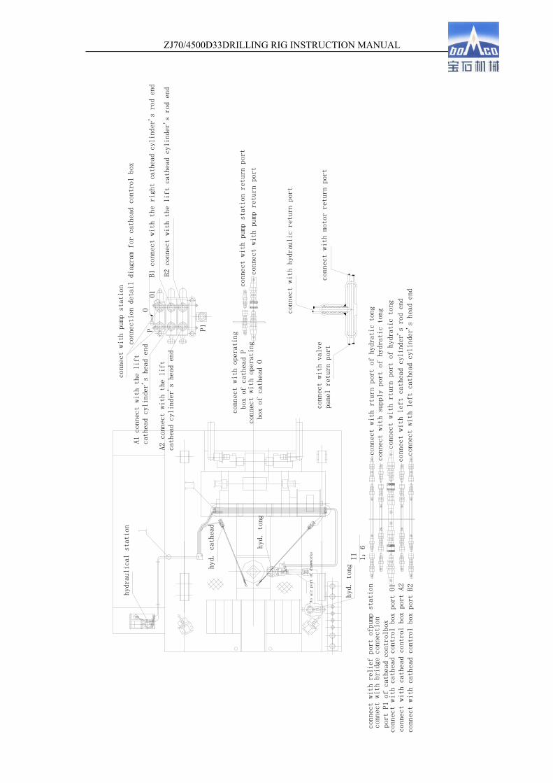
ZJ70/4500D33DRILLING RIG INSTRUCTION MANUAL
63
A1 conn
ect with the lift
cathe
ad cylinder's head e
nd
A2 connect
with the lift
cathead cyl
inder's head end
connect with operating
box of cathead O
connect wit
h valve
panel retur
n port
connect with operating
box of cathead P
conne
ct with supply port
of hydratic tong
connect with rturn port of hydratic tong
connect with left
cathead cylinder's
head end
connect with left cathead cylinder's rod end
connect with rturn port of hydratic tong
B2 connect
with the lift cath
ead cylinder's rod e
nd
conne
ct with pump station
return port
B1 connect with the right cathead cylinder's rod end
connect with motor return port
connect with hydraulic return port
conne
ction detail diagram
for cathead control
box
connect with
pump return port
conne
ct with pump station
OO1
P1
P
connect with bridge
connection
port P1 of cathead co
ntrolbox
connect with cathead control box port O1
connect with cathead control box port A2
connect with cathead control box port B2
connect with relief
port ofpump station
hyd. cathead
hyd. tong
to air port of drawworks
hyd. tong
II
1:
6
hydraulical station

ZJ70/4500D33DRILLING RIG INSTRUCTION MANUAL
64
Figure 3-2 Mechanized Wellhead Tools
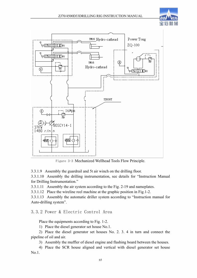
ZJ70/4500D33DRILLING RIG INSTRUCTION MANUAL
65
Figure 3-3 Mechanized Wellhead Tools Flow Principle.
3.3.1.9 Assembly the guardrail and 5t air winch on the drilling floor. 3.3.1.10 Assembly the drilling instrumentation, see details for “Instruction Manual for Drilling Instrumentation.” 3.3.1.11 Assembly the air system according to the Fig. 2-19 and nameplates. 3.3.1.12 Place the wireline reel machine at the graphic position in Fig.1-2. 3.3.1.13 Assembly the automatic driller system according to “Instruction manual for Auto-drilling system”.
3.3.2 Power & Electric Control Area
Place the equipments according to Fig. 1-2. 1) Place the diesel generator set house No.1. 2) Place the diesel generator set houses No. 2. 3. 4 in turn and connect the
pipeline of oil and air. 3) Assembly the muffler of diesel engine and flashing board between the houses. 4) Place the SCR house aligned and vertical with diesel generator set house
No.1.
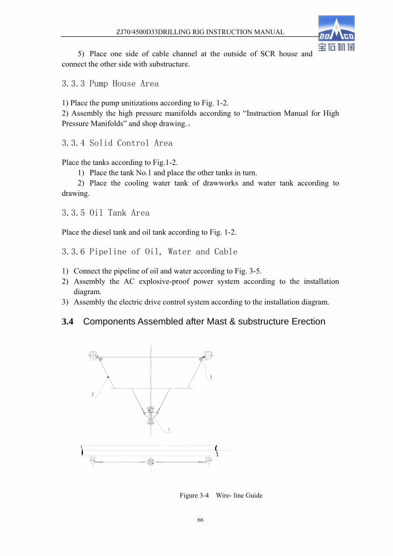
ZJ70/4500D33DRILLING RIG INSTRUCTION MANUAL
66
5) Place one side of cable channel at the outside of SCR house and connect the other side with substructure.
3.3.3 Pump House Area
1) Place the pump unitizations according to Fig. 1-2. 2) Assembly the high pressure manifolds according to “Instruction Manual for High Pressure Manifolds” and shop drawing.。
3.3.4 Solid Control Area
Place the tanks according to Fig.1-2. 1) Place the tank No.1 and place the other tanks in turn. 2) Place the cooling water tank of drawworks and water tank according to
drawing.
3.3.5 Oil Tank Area
Place the diesel tank and oil tank according to Fig. 1-2.
3.3.6 Pipeline of Oil, Water and Cable
1) Connect the pipeline of oil and water according to Fig. 3-5. 2) Assembly the AC explosive-proof power system according to the installation
diagram. 3) Assembly the electric drive control system according to the installation diagram.
3.4 Components Assembled after Mast & substructure Erection
Figure 3-4 Wire- line Guide
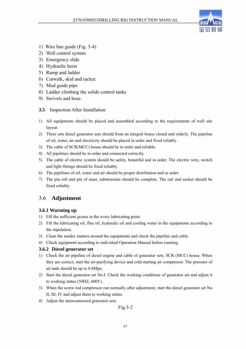
ZJ70/4500D33DRILLING RIG INSTRUCTION MANUAL
67
1) Wire line guide (Fig. 3-4) 2) Well control system 3) Emergency slide 4) Hydraulic hoist 5) Ramp and ladder 6) Catwalk, skid and racker. 7) Mud guide pipe 8) Ladder climbing the solids control tanks 9) Swivels and hose.
3.5 Inspection After Installation
1) All equipments should be placed and assembled according to the requirements of well site layout.
2) Three sets diesel generator sets should from an integral house closed and orderly. The pipeline of oil, water, air and electricity should be placed in order and fixed reliably.
3) The cable of SCR(MCC) house should be in order and reliable. 4) All pipelines should be in order and connected correctly. 5) The cable of electric system should be safety, beautiful and in order. The electric wire, switch
and light fittings should be fixed reliably. 6) The pipelines of oil, water and air should be proper distribution and in order. 7) The pin roll and pin of mast, substructure should be complete. The rail and socket should be
fixed reliably.
3.6 Adjustment
3.6.1 Warming up 1) Fill the sufficient grease in the every lubricating point. 2) Fill the lubricating oil, flue oil, hydraulic oil and cooling water in the equipments according to
the stipulation. 3) Clean the sundry matters around the equipments and check the pipeline and cable. 4) Check equipment according to individual Operation Manual before running. 3.6.2 Diesel generator set 1) Check the air pipeline of diesel engine and cable of generator sets, SCR (MCC) house. When
they are correct, start the air-purifying device and cold-starting air compressor. The pressure of air tank should be up to 0.8Mpa.
2) Start the diesel generator set No.I. Check the working conditions of generator set and adjust it to working status (50HZ, 600V).
3) When the screw rod compressor run normally after adjustment, start the diesel generator set No. II, III, IV and adjust them to working status.
4) Adjust the interconnected generator sets. Fig.3-2
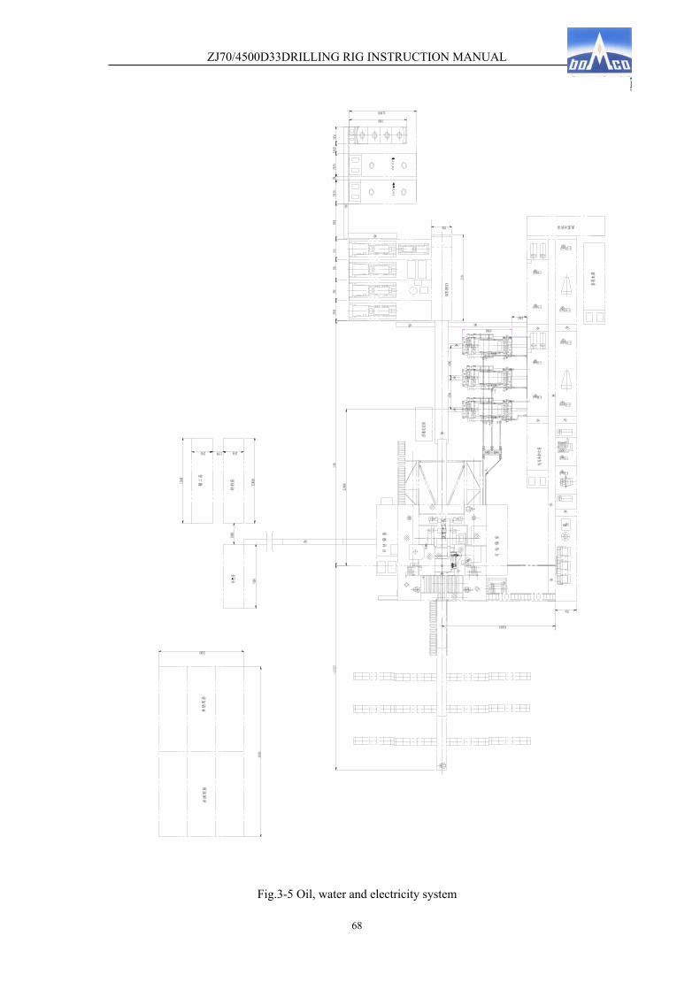
ZJ70/4500D33DRILLING RIG INSTRUCTION MANUAL
68
Fig.3-5 Oil, water and electricity system

ZJ70/4500D33DRILLING RIG INSTRUCTION MANUAL
69
3.6.3 SCR(MCC)
1) Check the power and control cable of SCR (MCC) house, DC motors, driller control box, foot switch, electromagnetic eddy current brake, lighting system and solids control system. All switches should be off-state.
2) Power the SCR (MCC) house by diesel generator set. Adjust the switch and indicator to assure that data is correct and parameter conforms to the requirements.
3) Zone power Power the driller control console and DC motors and check the indicating
light and switch. Start the motor fan of drawworks and motors and check the direction and working order.
Power the DC motor of mud pump and check the direction and working order. Power the air-purifying device, screw rod compressor and check the
indicating light and switch. Power the lighting system and check the working order of light fittings. Power the electromagnetic eddy current brake and start the cooling fan. Check
the direction and working order. Power the hydraulic station of mechanized wellhead tools and start the motor.
Check the direction and working order. Power the solids control system and check the direction and working order. Power the tanks of oil and water. Check the direction and working order. Power the other equipments and checking working order. Power the hydraulic supply of disc brake and start the motor. Check the
direction and working order.
3.6.4 Air-purifying device
1)Start the screw rod compressor No. I, II and adjust to working status according to the requirements in the operation manual. 2)Check the working order of air-purifying device to assure without air leakage and oil leafage.
3.6.5 Hydraulic disk brake
1) Check the pipeline and cable to assure that it is fixed correctly and reliably. 2) Adjust to the working status according to the operation manual of hydraulic disc brake.
3.6.6 Electromagnetic eddy current brake
1) Check the pipeline and cable to assure that it is fixed correctly and reliably. 2) Adjust to the working status according to the operation manual of electromagnetic eddy current brake.

ZJ70/4500D33DRILLING RIG INSTRUCTION MANUAL
70
3.6.7 Drawworks
1) Check and assure that the guard is complete and the pipeline is fixed correctly and reliably. All lubricating points should be filled with sufficient grease. 2) Open the ball valve of air tank of substructure and supply the drawworks with air. 3) Operate the control valve 5-10 times and check the logical relation, operation and brake.
Major Items: Flexibility of shift. Air-in and air-out of inertia brake. Air-in and air-out of clutch. Accuracy of overwind valve operation Reliability of locking shift Flexibility and reliability of brake
4) Under free position, Start the motor A (low speed) and check the direction. Start the motor B (low speed) and check the direction. Start the motor A and adjust the speed to 970r/min and pressure of lubricating oil to
0.25-0.35Mpa. Check the valve of oil supply point and assure that the lubrication is sufficiency and oil mass is proper.
Start the motor A and B at the same time. Adjust the motor by the hand wheel and foot switch. Check the oil supply and working order. Power-off the motor A and B, check the inertia brake.
5) Under I shift, start the motor and adjust speed to 970r/min. Drawworks run smoothly. The pressure of lubricating oil is stable and lubrication is sufficiency. Engage the high and low shift of drum, rotary clutch. Check the running and braking
status. 6) Under II shift, repeat the mentioned above items. 7) Adjusting requirements of drawworks:
Correct and flexible operation. Excellent sealing, without leakage. Stable pressure of lubricating oil, proper oil mass. Smoothly running, without abnormal shock and noises. Normal temperature rise of bearings.
3.6.8 Mud pump untinizations
1) Start DC motors; 2) Adjust mud pumps to working condition according to ‘mud pump operation
manual’.
ZJ70/4500D33DRILLING RIG INSTRUCTION MANUAL
71
3.6.9 Wellhead Mechanized Tools
1) Check and ensure all pipe are connected correctly and reliable. 2) Adjust hydraulic cathead, drill pipe tong and casing tong according to the
individual operation manual.
3.6.10 Drilling instrumentations
1) Check the sensors, cables and pipelines. 2) Adjust the indicator, indicate gauge according to operation manual.
3.7 Drilling Rig Erection
3.7.1 Mast Erection
1) According to Fig. 2-15, support the traveling blocks, hooks and balance sheave and rope should be leaded in.
2) When raising the mast, the wind speed should be less than 8.3m/s. 3) Raise the mast by the lowest shift of drawworks. When the mast leave the high bracket about
200mm, brake for 3 to 5 minutes and check the following items: Rope The fixed end of dead line should be reliable. The upright pole and cross beam of mast should be without deformation. The welding
seam should be without dehiscence. This inspection should do more than two times. When without abnormality, the mast can be raised formally.
When the mast leave the high bracket and has a about separation angle of 60°,start the buffer. The pipeline of buffer should be connected according to stipulation on the nameplate.
When the mast is vertical, assembly the U bolts connecting the A-bracket and mast. 4) Adjustment and alignment of mast (after substructure up)
Adjust the left and right direction of mast by the jack and shim under the stub of mast. Adjust the front and rear direction of mast by the screw on the top of A-bracket. The
theoretical position of screw should extend the locking nuts 125mm. After adjustment and alignment, the deviation between the center of crown blocks and
the center of rotary center should be less than 20mm.
3.7.2 Substructure Erection
(See DZ450/10.5-Xsubstructure operation manual for details)
Caution: the substructure should be raised smoothly and slowly and pay attention to the variation of weight indicator. If the reader of weight indicator increase suddenly or substructure is under abnormal conditions, stop the substructure up and place down the substructure. After the inspection and

ZJ70/4500D33DRILLING RIG INSTRUCTION MANUAL
72
trouble-shooting, raise the substructure again.
4 Use of Drilling Rig
4.1 Warning
1) The hydraulic hoist is for transfer the tool, weights, etc. It is for carry only cargo not people. 2) When the traveling blocks fall to the rotary table, the first layer wire line on the drum should
be not less than the 2/3 length of drum to prevent from sliding under high load of wire line clamp.
3) It is prohibited to check and repair the equipments without cut off the control supply. 4) Any body is prevented from staying around the safety valve and manifolds of mud pump
during drilling job. 5) The drawworks is engaged shift by the gear clutch. When shifting, the speed of motor should
be lowest. If shift under high speed, it may result the heavy accident. 6) The rig is lubricated by one-way pump. Under reverse, run 5 minutes and run 5 minutes
positive rotation to prevent from resulting accident for bad lubrication.
4.2 Attention to Drilling Rig Operation
1) During drilling jobs, two sets motor of drawworks should be compounded. Under the Max. Well depth, the drill stem can be tripped out by the drawworks under I shift with hook speed <0.25m/s when one set motor is failed.
2) During drilling jobs, adjust the speed according to loads and raising curve (Fig.4-1) to increase the usage of power.

ZJ70/4500D33DRILLING RIG INSTRUCTION MANUAL
73
Fig.4-1 Loads and raising curve
3) During tripping in, supply the brake hub with cooling water and power the electromagnetic eddy current brake. The cooling water should be softened water.
4) When fill lubricating oil for drawworks and mud pump, it should be closed to assure that the oil is clean.
4.3 Operation and Maintenance
4.3.1 The drilling team should have specialist in machinery, electricity and instrumentation to instruct the operation and maintenance of rig. 4.3.2 When rig has abnormal conditions, stop running and troubleshooting. 4.3.3 It is prevented from running under overspend, over temperature, over pressure and breach the stipulations. 4.3.4 According to the technical and running conditions, service the rig periodically. It includes shift maintenance, weekly maintenance, and monthly maintenance. Details see the Maintenance Manual of ZJ70/4500D Drilling Rig.
4.3.6 Operation and Maintenance During Heavy Frost
4.3.6.1 Circulating System (1) Check the valve and manifolds before pump running to assure without freeze. (2) When pump stopping, discharge the drilling fluid in the fluid end of pump,
swivel and high and low pressure manifolds. 4.3.6.2 Hoisting system
1) After tripping down the drill stem, discharge the cooling fluid in brake hub. 2) To prevent the liquid outlet under lifting bail of swivel from freezing.
4.3.6.3 Other system 1) when the temperature is less than -20℃, should make preventive measures to prevent from
damaging of main structure of mast and substructure. 2) Operators should make preventive measures to prevent from frostbite of pipeline of oil, air,
钩载
档
档
档
档
钩速

ZJ70/4500D33DRILLING RIG INSTRUCTION MANUAL
74
water and control valve. 3) Operators should make preventive measures to prevent from freezing of driller console
and instrumentation.
5 Disassembly and Transportation
5.1 Rig down
Rig down is reverse to rig up. Place down the substructure firstly and place down the mast.
5.1.1 Substructure down:
Push the substructure to off-centered position by the buffer oil cylinder and place down slowly by its sole weight.
Caution: 1) All parts impacting the substructure down, such as ramp, ladder, slide and
hydraulic hoist, etc should be removed. Details see the Operation Manual of DZ450/10.5-S substructure.
2) Owning to the heavy weight of 350t it should be placed down in uniform speed.
3)Before substructure down, remove the ladder of rear floor.
5.1.2 Mast down:
Before mast down, hang the balance sheaves and push the mast to off-centered position by the buffer oil cylinder and place down slowly by its sole weight.

ZJ70/4500D33DRILLING RIG INSTRUCTION MANUAL
75
Caution: 1) Remove the casing stand and parts impacting the mast down.
2) Place mast down slowly in uniform speed.
5.2 Disassembly
Disassembly rules: it is inverse to the assembly. Notes: 1) All removed connector of air, liquid and water should be sealed to assure clean and
preventing from entering of matters. 2) The butted hole of drawworks should be sealed. 3) The bolts of cardan shaft are high strength bolts. They should be kept carefully to
prevent from garbling with other bolts.
5.3 Transportation
Owning to different transporting vehicles, there is different transporting models. The following items are for reference only: 1) Drawworks
The drawworks should be transported by two sections: power unit and drawworks body. When the drawworks is overweight, the electromagnetic Eddy Current brake can be removed. 2) Catwalk and cable channel
The cable channel climbing the drilling floor can be shipped individually. Other cable channel can be shipped with catwalk. Stack the two sections of catwalk and fix with pins. The cable forwarding to the pump and solids control system should be placed in the lower catwalk and water pipeline channel should be placed in the upper catwalk and should be fixed. 3) Rotary driven assembly
Remove the cardan shaft and ship with other parts. The motor should be shipped with base. The left main body should be shipped individually.

ZJ70/4500D33DRILLING RIG INSTRUCTION MANUAL
76
6 List of outsourcing transmission parts
6.1 Bearings
Item Description Size Qty. Remarks
1 Self-aligning roller bearing 22230C/W33/C3 Φ150×Φ270×73 2 Input shaft of drawworks
power unit
2 Self-aligning roller bearing 22338C/W33/C3 Φ190×Φ400×132 2 Block bearing of drive shaft
of drawworks
3 Self-aligning roller bearing 23048C/W33/C3 Φ240×Φ360×92 1
Free sprocket bearing of drive shaft of drawworks Shift I
4 Single row roller bearing 32148 Φ240×Φ360×56 1
Free sprocket bearing of drive shaft of drawworks Shift I
5 Self-aligning roller bearing 23040C/W33/C3 Φ200×Φ310×82 1
Free sprocket bearing of drive shaft of drawworks Shift II
6 Single row roller bearing 32140 Φ200×Φ310×51 1
Free sprocket bearing of drive shaft of drawworks Shift II
7 Self-aligning roller bearing 22244C/W33/C3 Φ220×Φ400×108 2
Block bearing of drum shaft
8 Self-aligning roller bearing 22240C/W33/C3 Φ200×Φ360×98 2
Free sprocket bearing of drum high & low speed
9 Single row roller bearing 32240 Φ200×Φ360×58 4
Free sprocket bearing of drum high & low speed
10 Self-aligning roller bearing 32230C/W33/C3 Φ150×Φ270×73 2
Block bearing of sand drum
11 Self-aligning roller bearing 22234C/W33/C3 Φ170×Φ310×86 1
Block bearing of sand drum
12 Single row roller bearing 32234 Φ170×Φ310×52 2
Block bearing of sand drum
13 Self- aligning roller
bearing 22226C/ W33/C3
Φ130×Φ230×64 2 Input shaft of rotary table driving box
14 Single row roller bearing NU1028 Φ140×Φ210×33 2 Input shaft of rotary table
driving box
15 Ball bearing 6028 Φ140×Φ210×33 2 Input shaft of rotary table driving box
16 Self-aligning roller bearing 22228C/W33/C3
Φ140×Φ250×68 2 Output shaft of rotary table driving box
17 Thrust ball bearing 8134 Φ170×Φ215×34 2 Make up and break down cathead
18 Thrust ball bearing 8226 Φ130×Φ190×45 2 Make up and break down cathead
19 No outer ring long column roller bearing 124721
Φ105×Φ146×66 4 Make up and break down cathead
20 Self-aligning ball bearing 1207
Φ35×Φ72×17 12 Left and right block drum of cathead
21 Ball bearing 218 Φ90×Φ160×30 2 Water and oil coupling of drum shaft

ZJ70/4500D33DRILLING RIG INSTRUCTION MANUAL
77
22 Bearing L357049/L357010D Φ304.8×Φ393.7×107.95 7 Sheaves of TC7-450 crown
block
23 Short column roller bearing 42238 Φ190×Φ340×55 1 sand sheaves of TC7-450
crown block
24 Short column roller bearing 42316 Φ80×Φ170×90 7
Auxiliary sheaves of TC7-450 crown block, wireline guider
Note:the bearings of other equipments see individual operation manual.
6.2 Chains and Belts
Item Description Qty. Remarks 1 Roller chain 24S-6(1 1/2-6) 136 segments ShiftⅠ of drawworks 2 Roller chain 24S-6(1 1/2-6) 120 segments shiftⅡ of drawworks 3 Roller chain 32S-4(2-4) 114 segments Low speed of drum 4 Roller chain 32S-4(2-4) 90 segments High speed of drum 6 Roller chain 32S-2(2-2) 82 segments Cathead 7 Roller chain 24S-4(1 1/2-4) 260 segments Rotary table driving
box 8 V belt 1×5ZV25J-2720+2×4ZV25J-7620 6 sets For 3 F-1600 mud
pump untinizations
7. Notice for anti-collsion In order to guarantee the person and equipment safety , reliable safey sytem is installed to prevent the collision of travelling system and crown block.. So please read the following manual and do it strictly as required and ensure the safety.
Cautions:
When raising the mast and substructure, it can not adjust the anti-collision system to normal working conditions.So driller should be opearate it carefully and raise them slowly as soon as possible. Brake immediately when it is abnormal.
1. Operation and check after rig assembly.( new drilling rig, assembly after moved to a new place) 1) Adjust the overrun limit valve positon in left and right direction, position of valve rod and faten them in the right position.Test its working performace. Recommend it to shut off power and brake in the position of 7~6 m away from the bottom of crown block . (Above date only for reference and operator can choose the suitable and safe distance according

ZJ70/4500D33DRILLING RIG INSTRUCTION MANUAL
78
real situation.) 2) Assemble the wireline anti-collision device on the top section of mast. Lubricate the system. Ensure thin wirline no hander when it passes the different guide pulley .Do the follwing test before connecting the valve and end of thin wireline. a) Connect the two position and three way valve 2-HA-1 in the valve seat of back mast and make it work . Becaust it does not need to work when raising the mast , substructure, it does not connect thin wireline and get through. b) Operate 2-HA-1 valve handle by hand. c) Discharge air and release the anti –collision . d) Relese valve handle and make heavy ball falling . it makes control air to produce a signal to syatem and shut off the power, disk brake will brake right away. e) Do above test two or three times and make sure it in good conditions. Operate handle and tense the thin wirline and valve handle, connect thin wireline with '' weak section'' ,then heavy bob can drop slightly after hand is free.Attention: it shall not make the air valve change direction, or adjust it according to the process in clause e). Two kinds of connecting type described as below. It can form a weak section and take action to shut off power and brake immediately before the accident happens. Coustomer can choose anyone of them according to real requirementsand habit. 1) Use a iron wire (Ø 3.5, about 300 ㎜ long) to connect the thin wireline and heavy bob.Iron wire shall be open or U type and prohibited to close or twist it. 2) Use a cotter pin to connect the thin wireline in the top and insert the another parts to hole in the end of heavy bob. Notice that cotter pin shall be vertical and split the tail of cotter pin. If it is not vertical, turn around the heavy bob lightly,then tightn the lock nut. No matter what you choose, it shall do it in accordance with the instruction of section 3 in this manual '' requirement and test for lever connecting piece of anti-valve'' in the first time in order to make sure this device is safe and reliable. 2 Check daily 1) Check every shift Before each shift begins, pull down the overrun limit valve lever to check and ensure the limit valve working normal. After checking every time, press the anti- collision release valve before engaging the drum and operate disk brake tong or brake cylinder, make them release. Turn around the drum slightly and pull the limit valve lever to the upright position. It is normal working conditions. 2) Check every week. Release the connecting parts of anti-collision valve lever and lever is falling . Anti –collisison device should work or find the reason . Check it again and ensure it work normal , do the following process. Check all parts along the thin wireline from top to bottom and ensure no any hinder. Lubricate it again if necessary. Do the process according to the requirement from b) to e) in section 2 ) and then begin to work. 3) check digital anti-collision check according to section 3).

ZJ70/4500D33DRILLING RIG INSTRUCTION MANUAL
79
3 Requirement and test to lever connecting parts in anti-collision valve. 1) Requirement to connecting iron wireof anti-collision lever. a)Use the required Ø 3.5 “general usage of cold galvanizing low carbon steel wire. ” (GB343-82).It is absolutely prohibited to use electrode or other wire. b) Do it according to the above requiremnt. Two end connecting iron wire should form a full open, similar to U type, circular trench. The extension tail is about 10~15 ㎜, not too long. Prohibited to close or twist it to dead angle. c) Hang one or several weights, acurate iron and make total weights to 6 ㎏ in the bottom of heavy bob, At this time, U type ring shall be drag straight and heavy boa nad weight will fall in together. If it do not work, adjust the bend angle and reduce the length extended to make it work, or change a more thin iron wire, test it again and again untill it works. Do it later as the above process if necessay. 2 ) Requirement for cotter pin of anti-valve lever. a) Choose it according to the diameter of inner hole of annual parts in heavy bob end . cotter pin : Ø 4~ Ø 8 (GB91-86),length : 60~80 ㎜. b) Split of tail is up to the experience and real situation. Only permit to adjust the split and prohibite to bend the tail up. c) Hang one or several weights, acurate iron and make total weights to 6 ㎏ in the bottom of heavy bob, At this time, tail split shall be drag straight right away and heavy bob and weight will fall in together. If it do not work, adjust the tail split to make it work, or change another type cotter pin , test it again and again untill it works. Do it later as the above process if necessay.

ZJ70/4500D33DRILLING RIG INSTRUCTION MANUAL
I
CONTENTS
1.1 CHAPTER 1 GENERAL APPLICATION AND FEATURES ................................................................2 1.2 DESIGN AND MANUFACTURE STANDARD FOR DRILLING RIG ZJ70/4500D.....................................2 1.3 TECHNICAL SPECIFICATIONS...........................................................................................................3 1.4 GENERAL ARRANGEMENT FOR DRILLING AND TRANSMISSION BRIEF INTRODUCTION......................4 1.5 LIST OF DRILLING RIG COMPONENTS AND EQUIPMENT(JUST FOR REFERENCE OF MATCHED PARTS, IT IS NOT THE SUPPLY SCOPE)................................................................................................................9
CHAPTER 2 MAIN PARTS AND COMPLETEMENT PARTS FOR DRILLING RIG .............12
2.1 JC-70D DRAWWORKS ..................................................................................................................12 2.3 TC7-450 CROWN BLOCK ...............................................................................................................28 2.4 YC-450 TRAVELLING BLOCK........................................................................................................30 2.4.1 TECHNICAL SPECIFICATION ..........................................................................................................30 2.5 DG-450 HOOK..............................................................................................................................31 2.6 SL-450 SWIVEL ............................................................................................................................32 2.7 JJ450/45-K14 MAST.....................................................................................................................37 2.7.1 APPLICATION................................................................................................................................37 2.8 DZ450/10.5-S SUBSTRUCTURE ....................................................................................................40 2.9 AIR SYSTEM ................................................................................................................................41 2.10 DRILLING INSTRUMENTATION ..................................................................................................49 2.10.1 MAIN FUNCTIONS ......................................................................................................................49 2.11 MECHANIZED WELLHEAD TOOLS ...............................................................................................50 2.11.1 FUNCTION ..................................................................................................................................50 2.12 F-1600 MUD PUMP UNITIZATIONS ...........................................................................................51 2.13 HIGH PRESSURE MANIFOLDS ...................................................................................................52 2.14 POWER SYSTEM ........................................................................................................................52 2.15 ELECTRIC DRIVE AND CONTROL SYSTEM .................................................................................57
3 INSTALLATION AND COMMISSIONING....................................................................................58
3.1 WARMING UP...............................................................................................................................58 3.2 DRILLING RIG FOUNDATION.......................................................................................................59 3.3 INSTALLATION .............................................................................................................................61 3.4 COMPONENTS ASSEMBLED AFTER MAST & SUBSTRUCTURE ERECTION..............................66 3.5 INSPECTION AFTER INSTALLATION................................................................................................67 3.6 ADJUSTMENT...............................................................................................................................67 3.7 DRILLING RIG ERECTION ...........................................................................................................71
4 USE OF DRILLING RIG...................................................................................................................72
4.1 WARNING.....................................................................................................................................72 4.2 ATTENTION TO DRILLING RIG OPERATION................................................................................72 4.3 OPERATION AND MAINTENANCE ................................................................................................73

ZJ70/4500D33DRILLING RIG INSTRUCTION MANUAL
II
5 DISASSEMBLY AND TRANSPORTATION ................................................................................74
6 LIST OF OUTSOURCING TRANSMISSION PARTS ................................................................76

ZJ70/4500D33 DRILLING RIG
OPERATION MANUAL
AZ702135-SM
OCT, 2005