Prefabrication of substructures for single-detached ...
35
Prefabrication of substructures for single-detached dwellings on reactive soils: a review of existing systems and design challenges Bertrand Teodosio a *, K.B.K. Shanaka a , P. Mendis a and D. Heath a a Infrastructure Engineering, The University of Melbourne, Parkville, Australia
Transcript of Prefabrication of substructures for single-detached ...
Prefabrication of substructures for single-detached dwellings on
reactive soils: a review of existing systems and design challenges
Bertrand Teodosioa*, K.B.K. Shanakaa, P. Mendisa and D. Heatha
aInfrastructure Engineering, The University of Melbourne, Parkville, Australia

Prefabrication of substructures for single-detached dwellings on
reactive soils: a review of existing systems and design challenges
The possible thriving Australian construction industry for residential structures
has been hindered by skilled labour shortage and eventually triggered housing
shortage and affordability crisis. Prefabrication is a promising method to alleviate
issues related to housing shortage and affordability by reducing material wastage,
construction delays, weather impacts, unexpected costs, skilled labour
dependence and construction risks. The full potential of prefabricated
construction is yet to be realised in part due to most of developments being
focused on its superstructure. Prefabricated substructures should conform with
the Ultimate Limit State (i.e., strength capacity) and the Serviceability Limit
State (i.e., allowable deformation and damage) stated in the Australian Standards.
One of the important considerations is the impact of reactive soils to residential
structures that causes financial damages globally. These reactive soils are clayey
grounds that change significantly in volume due to change in soil moisture. Due
to the initiatives to alleviate issues of housing crisis, skilled labour shortage and
unpredictable house damage, it is necessary to review the existing available
substructures suitable for single-detached dwellings on reactive soils and to
evaluate the necessary considerations and challenges in developing prefabricated
substructures. This review will help understand the present state of the design and
construction industry and the efforts of inventors and designers to reduce
damages due the shrinking and swelling ground movements. This review also
guides product developers to design systems having robust performance without
compromising practicality.
Keywords: Substructures; foundation design; single-detached dwellings; reactive
soils; prefabricated construction; design for manufacturing and assembly;
housing crisis; skilled labour shortage
Introduction
The positive Australian economic environment and population increase have led
to a growing demand for residential structures. The Australian property market for
dwellings has seen consistent increases of approximately 3% per annum since 1970s
(Stapledon, 2010). The average total number of dwelling commencements from 2001 to
present is on average 150,000 per year (Australian Bureau of Statistics, 2017) and yet,
the cumulative housing shortage is still around 220,000 (Cannington, 2017). This strong
demand for houses and acceptable rate of dwelling completion has been countered by a
shortage of skilled trades which has constrained sustainable growth in the housing
industry (Lewis, 2017). In turn, there have been price increases, material and labour
shortages, issues related to construction quality and delays (Yu et al., 2008).
Prefabricated housing offers a solution for these challenges by building houses with less
waste, greater certainty for building costs, improved site safety, controlled quality of
materials and workmanship, and shorter construction cycle time (Lichtenberg, 2006).
Furthermore, prefabrication only requires in-situ assembly reducing the necessity for
skilled trades for site preparation, general building, bricklaying, carpentry, ceramic
tiling, joinery, plastering, other trades (Gibb, 1999).
Prefabrication, the method of constructing off-site and then transporting and
assembling on-site, has been adopted for the superstructure of residential houses for
many years (Yu et al., 2008). Significant advancements in the design and construction
of superstructures have increased the number of prefabricated houses built in most
developed countries like Japan and the United States of America (Barlow and Ozaki,
2005; Song et al., 2005). Safety of prefabricated elements has also been globally
investigated to assure the robustness of superstructures (Friedman, 1992). Most
innovations have been focusing on the superstructure of houses and conventional
methods for the construction of the substructure of houses are still the preferred
approaches (Pujadas Gispert, 2016). Construction of substructures using traditional cast-
in-place concrete causes site disturbance, which leads to environmental degradation and
construction delays (Nelson, 2008).

The prefabrication of substructures has the potential to have a positive impact on
the housing industry by improving construction quality, improving sustainability,
reducing construction delays, reducing the industry’s reliance on skilled labour, and
increasing certainty in project expenses (Monash University, 2017).
To date there has been minimal development of prefabricated substructure
solutions that are suitable for low-rise single-detached dwellings on reactive soils.
Prefabricated substructures should conform with the Ultimate Limit State (i.e., strength
capacity) and the Serviceability Limit State (i.e., allowable deformation and damage)
stated in the Australian Standards. One of the important considerations is the impact of
reactive soils to lightweight structures, such as single-detached dwellings and
pavements, since these are more susceptible to experience the shrink and swell
movements caused by the decrease and increase in soil moisture content between
seasonal changes and root water uptake of vegetation (Teodosio et al., 2018). These
shrink-swell movements can cause damage requiring minor repair to major overhaul to
the entire lightweight structures (Li and Cameron, 2002). The cost of damage due to the
change in volume of reactive soils amounts to billions of dollars annually worldwide
(Jones and Jefferson, 2012; Miao et al., 2012; Skinner et al., 1998; Cameron et al.,
1987; Krohn and Slosson, 1980).
Due to the initiatives to alleviate issues of housing crisis and to minimise
unpredictable house damage, it is necessary to review existing available substructures
suitable for single-detached dwellings on reactive soils that will provide as benchmarks
to develop prefabricated substructures considering challenges in design and
implementation. This review will help understand the present state of the design and
construction industry and the efforts of inventors and designers to reduce damages due
the shrinking and swelling ground movements of reactive soils. This review also guides
product developers to design systems having robust performance without compromising
practicality for a better market uptake of prefabricated substructures for dwellings.
Existing substructures for single-detached dwellings
Conventional substructures
The Australian Standard 2870: Residential slabs and footings (Standards
Australia, 2011a) sets out the criteria for site classification for reactive soils and the
design and construction of typical substructures used in Australian residentials. The
substructures being used in practice for houses are waffle raft and stiffened raft, which
are both slab substructures. The site class is assigned base on the characteristic surface
movement (ys) due to expansion and shrink of reactive clayey soils (Table 1), calculated
using
𝒚𝑺 =𝟏
𝟏𝟎𝟎∑ (𝑰𝒑𝒕∆𝒖̅̅ ̅̅𝑵𝒏=𝟏 𝒉)𝒏 =
𝟏
𝟏𝟎𝟎∑ (𝜶𝑰𝒑𝒔∆𝒖̅̅ ̅̅𝑵𝒏=𝟏 𝒉)𝒏, (1)
where Ipt is the instability index (pF), ∆u is the average soil suction change over the
layer thickness (pF), α is the lateral restraint factor, Ips is the soil shrinkage index
(%/pF), h is the layer thickness, and N is the number of soil layers. The specification of
a suitable substructure (depth of the beams and internal ribs, size and amount of
reinforcement) depends on the classification of sites and the nature of the superstructure
(e.g. full masonry, articulated masonry, brick veneer, cladding, weatherboard, etc.). For
expected surface characteristic movement and for given wall system, differential
settlement is limited by selecting adequate stiffness for substructures so that
superstructures will have permissible damage levels.
One of the most commonly used substructures in Australia is the waffle raft due to
the advantage in construction and cost (Figure 1). It is comprised of closely spaced
beams and voids created by formed voids (e.g. Expanded Polystyrene (EPS),
polypropylene (PP), polyethylene (PE) or card board formwork). The spacing of
internal beams is approximately 1.1 m centre-to-centre with an internal beam width
equal to 110 mm. The internal and edge beams vary depending on the house wall
system (i.e. clad frame, articulated masonry veneer, masonry veneer, articulated full
masonry and full masonry) and its site classification (Class A, S M, H1, H2 and E). A
minimum of 300 mm wide edge beam is required for full masonry, masonry veneer and
articulated masonry veneer systems while 110 mm wide edge beams are required for
cladding frames. The internal and edge beam depths range from 300 mm to 1100
mm as specified in AS 2870. Beam excavation is not necessary since the system is
installed on-ground. The slab thickness of waffle rafts is typically thinner (85 mm) than
stiffened slabs (100 mm).
The construction of waffle raft starts with ground levelling since waffle
raft needs to be laid out on a levelled surface. Due to this, a waffle raft system is
commonly used in sites that do not have significant slopes (e.g. sites requiring cut and
fill). The construction of substructures depends on the floor area, complexity of the
design and available skilled workers. The waffle pods made of EPS are simply laid out
for half a day and takes two to four hours for steel reinforcements placing and
concreting. Curing typically lasts for three to seven days and installation of
superstructures commences after seven to fourteen days. It is worth noting that curing of
concrete commonly takes around twenty-eight days, however, since fixing timber frame
does not have significant load, structural engineers or builders specify earlier
superstructure construction commencements. Thus, the total time to construct a waffle
raft is approximately between five and ten days.

Waffle rafts are not usually advised to be installed in areas with high cyclonic
winds since the whole substructure is resting on the ground without anchors and there is
limited resistance to uplift forces.
Another common substructure is a stiffened raft, comprised of reinforced
concrete beams and slabs across the entire floor plan (Figure 2). Excavation is necessary,
and this is dependent on the depth of beams and slab thickness. The excavation for the
internal and edge beams commonly takes around one and a half to three days depending
on how many skilled labours are working on a site. Formwork is then installed that lasts
for half to a full day, and concrete is poured in-situ lasting for two to four hours. The
slab is usually raised above the ground level to ensure that stormwater will not flow into
the house and cause damage. The stiffened raft requires significant site preparation
including grading, excavation, formwork setup and concrete curing. The total period to
construct a stiffened slab extends from seven to fourteen days or longer.
Slab substructures (i.e., waffle raft and stiffened raft) are advantageous in sites
where the depths of reactive soils make costs of deep substructures prohibitive and
basements are not used. In extreme reactive and problematic sites, a pier-and-beam or a
pier-and-slab system are designed in accordance with engineering principles (Appendix
G, AS 2870-2011 of Standards Australia, 2011). These deep substructures incorporate
bored or bulk piers or piles and reinforced concrete beams or slabs, which eliminate
effects of heaving soil through isolation. Pier-and-beam or Pier-and-slab systems can
reduce the total and the differential settlement of houses by transferring applied
structure loads to a deeper and stronger subsurface layer taking advantage of the skin
friction of soils. The depth-to-width ratios of these systems are equal to or greater than
5.0. These systems are more expensive than slab systems (i.e., waffle rafts and stiffened
rafts) and cause greater site disturbance requiring skillful installations using heavy and
specialised equipment.
Isolated and strip footings are not commonly used in sites with moderate to
highly reactive soils due to the non-uniform global behaviour of these types of
substructures (Department of the Army USA, 1983). Isolated and strip footings are
often constructed in more stable sites where the predicted movement, ys, is less than 15
mm.
Block masonry piers or pads with ground anchors are also used as
substructures, which are common in the United States of America (Manufactured
Housing Research Alliance, 2002). Stacked block piers can be a single block pier or a
double block pier (Figure 3). The pads can be a double pad or a triple pad and are
installed under the main beams of prefabricated houses. The typical block pier or pad
height ranges from 0.9 m to 2 m off the ground and spaced from 1.5 m to 3.0 m apart
depending on the house design and soil type. The ground anchors are attached to the
beams of prefabricated houses using steel straps to resist wind uplift forces. This
footing system is adaptable to local site conditions and does not require a strict
dimensional manufacturing and installation tolerance. Perimeter walls made up of
stacked blocks may also be a part of a substructure. Reinforced block piers are also
available supporting chassis where prefabricated houses are placed above (Federal
Emergency Management Agency, 2009). This chassis is comprised of steel beams
similar to the footing system of Moonen and Hermans (2013). The chassis beams are
ideal since its light weight and can easily be assembled. The performance of the system
for reactive soil has not been tested yet. This footing system has an advantage when
installed on reactive soils since the contact between the substructure and ground is
minimised.
Block masonry piers or pads with ground anchor systems are constructed on a
compacted or undisturbed ground. The installation of piers and ground anchor
substructure is frequently completed in one to two working days. Though, the use of a
pier and ground anchors, in most cases, is not considered as a stand-alone substructure
for a single-detached dwelling. Addition of a perimeter encasement around the property
is necessary acting as concrete wall support, forming a crawl space. Contrarily, the cost
of crawl spaces is generally more expensive than slab systems and the construction
period ranges from three to five working days (Manufactured Housing Research
Alliance, 2002).
Unconventional substructures
Many on-ground substructures are derived from waffle rafts. For instance, a two-
way post-tensioned waffle raft system was designed by Moldovan and Mathe (2016) to
decrease the slab thickness and suffice ductility requirements. Other substructures
derived from the typical waffle raft has EPS spanning across the entire floor area to
provide passive insulation for houses. Marquez (2012) developed modular formwork,
which are laid out on the ground and concrete is then poured. Likewise, a PE formwork
similar to the shape of the EPS of waffle pods was developed to ease the placement of
reinforcing bars, steel mesh and concrete (Kivi, 2013). A dome formwork (Figure 4), on
the other hand, has a mould with cone support at the middle. Each dome inter-connects,
providing a supplementary damp-proofing for capillary action with impervious liners.
Additional reinforced beams or piles are used for sites with reactive soils (Kivi, 2013).
The site preparation and construction period of these substructures are similar with that
of waffle rafts.
Another novel substructure includes braced masonry piers or cast-in-place
concrete pads with metal straps (Figure 5) that are utilised to resist vertical and lateral

loads such as extreme wind conditions and earthquakes (Federal Emergency
Management Agency, 2009). The metal straps are integrated in the footing system
redistributing the loads to adjacent portions of the footing system. Though, if straps
are loaded to their maximum capacity, redistribution of load may lead to progressive
failure and collapse. To prevent progressive failure, redundant straps are necessary but
may be inefficiently designed. These systems require typical ground improvement
techniques such as ground compaction and application of gravel. The metal straps are
installed and act as tie-downs to secure the house in place. The installation of these
systems commonly takes approximately three to seven days, depending on the
configuration of a proposed substructure.
Alternatively, a substructure comprised of a galvanised steel pan having a 3-bolt
connected tubes (Figure 6) can be used. The V-shaped component has tubes connected
with the pan by carriage bolts known as a beam clamp. The other ends of the tubes are
then attached to the flanges of I-beams using connectors. The mechanism relates to the
tension and compression load distribution from the base pad at one pier to the I-beams.
This system can also be used for retrofitting existing substructures. This system is
supplementing main substructures (e.g., block piers, pads and suspended beams) that
can replace grounds anchors and metal straps. The installation generally takes around
forty minutes to an hour per unit.
A hybrid substructure option is comprised of structural panels attached around
the perimeter of houses with pour-in concrete (Figure 7). Concrete is cast into the
structural panels that will act as a perimeter wall support. Block piers with beam
supports are still necessary under the middle area of single-detached dwellings. Typical
site preparation is required for installation, which includes grading and levelling.
Installation time is affected by weather condition, site conditions and slopes. A typical
construction of this substructure ranges from two to three days.
An alternative option is a substructure made up of several components including
a pivoting deadman (Figure 8). It is applicable to most types of soil except gravelly sand
grounds with little or no fines, since these soils does not have the cohesion the deadman
mechanism requires. Houses are connected by a telescoping arm consisting of a locking
frame clamp that transfers both tension and compression loads to the pivoting deadman.
This system is a supplementary to other types of main substructures (e.g., block piers
and pads) and the installation vary dramatically depending on the complexity of
construction. The installation commonly takes around twenty minutes to an hour per
unit.
Another substructure is made up of a permanent steel support column that
replaces blocks and anchors of houses (Figure 9). It is designed to be fastened to I-beam
flanges that has an adjustable cap plate that can be positioned to a desired elevation. In
almost all cases, the installation time is faster than that of the conventional anchoring
systems currently utilized. Under standard conditions with typical ground compaction as
site preparation, installation should take no longer than one to two days for two people,
with regards to setting of the anchors (Manufactured Housing Research Alliance, 2002).
Once the installation is finished, the height cannot be adjusted since the rotation of the
cap plate is restricted. The forces are transferred by the footing system to the cast-in-
place concrete pad, typically the surface of an isolated or a strip footing. This system
has the advantage of adjusting the slab in case of differential settlement due to soil swell
and shrink, differential loading conditions, uneven ground conditions and earthquakes.
Micropile systems are emerging substructures for single-detached dwellings.
These are solid pin substructures that are embedded into the ground without digging
holes or pouring concrete (Figure 10). It is comprised of precast concrete or reticulated
steel head installed on the ground surface, the steel bearing micropile are driven through
the head using specialised hand-held tools. However, this substructure can only carry
light structures such as decks, boardwalks, trails and pedestrian bridges. Further design
analysis should be performed for housing application. It may also be challenging to
drive into hard soil strata, which may cause initial deflection due to installation. Another
variation of the micropile system uses multi-directional pin caps and piles, which
provide support to the superstructure by resisting vertical loads including uplift, shear
and moment loads. Minimal earthwork is necessary and can often be readily installed,
nevertheless, these systems cost approximate twice as much as slab systems for the
material cost. The installation of these micropile systems requires handheld drivers
(e.g., 14-18 kg or petrol jackhammer for standard penetrable soil or impact drivers with
proper hex and screw sizes). The installation is approximately fifteen minutes per group
of micropiles. Typical suspended slabs can be poured or installed following standard
construction process and time. Modular houses can be readily placed above the concrete
or steel head.
An alternative substructure is an integrated wall-and-slab system, which also
serves as a basement. The wall is constructed off-site using a high-strength, low-water
concrete with no additional damp-proofing required while the slab is poured on-site with
steel reinforcements and polypropylene fibres for a monolithic structure (Figure 11). Yu
et al. (2008) also developed a similar footing system that is efficiently constructed in
harsh climates. This footing system also reduces the depth of expansive soils prone to
moisture changes by excavating the ground for a basement. Nevertheless, it is prone to
lateral pore water pressure that necessitates the installation of drain pipes to reduce the
moisture and stress experienced by the walls. The expected construction time for this

precast system, including the assembly of basement walls, placing of steel and pouring
of concrete for the substructure, capping with the main floor and soil back filling, is less
than five days. This is significantly shorter than the typical cast-in-place construction of
thirty-six days.
An integrated formwork for pier systems can also be used for houses. Permanent
pier formwork was developed to easily pour concrete into the moulds and to control the
quality of footings. Excavation is necessary depending on the depth of piers, and the
standard construction period takes around three to five days depending on the chosen
house design and site conditions. The form is installed with body snaps together with
no additional specialised tools required but manual labour is needed for excavating the
soil. Custom-fabricated vertical and horizontal rebars can also be placed using the rebar
holder in- side the form (Figure 12). The integrated rebar holder reduces the amount of
concrete needed and properly locates and holds rebars. Since this formwork only has one
available dimension, there will be limited options that may cause an inefficient design.
Advantages of prefabricated substructures
The benefits of prefabricating substructures shall be recognised to know their
feasibility to be prevalent in the future construction practices. The advantages of
prefabricated systems depend on the building type and quantity for installation affecting
the design viability, construction speed and substructure cost. Other benefits of
prefabrication include better material quality control, fewer risks and a more sustainable
construction method. This section provides the benefits of prefabricating substructures
based on studies related to this topic and further discuss the potential substructures
where prefabrication can be incorporated.
If the building type of the structure to be built is a low-rise lightweight and a
large concrete volume is to be installed, prefabricated substructures will be a practical
option. Prefabricated substructures will be more practical if implemented with low-rise
lightweight structures such as prefabricated houses, this application is more technically
feasible compared to tall and heavy buildings due to lower loads involved (Kumar, 1972).
The quantity being installed also plays an important role to achieve significant savings
(Wren, 2012). Prefabricated substructures in residential schemes is a more suitable
alternative for large-scale construction since handling and transportation costs are
important considerations, which are reduced when installed in large volumes (Huat and
Mohammed, 2006). When dealing with a large-scale project, the lead time of
substructure installation may be reduced since the components are efficiently procured
and readily assembled on-site; this in turn allows onsite work to commence on the
superstructure sooner (Wren, 2012).
With the use of prefabricated substructures, the construction period may be
considerably reduced. The lead time for formwork installation, concrete curing and
formwork decommissioning in constructing traditional cast-in-place residential
substructures are eliminated (Moonen and Hermans, 2013; Yu et al., 2008). The delays
due to inclement weather will also be prevented through effective planning and efficient
procurement (Kumar, 1972). In addition, the delays due to different material delivery
schedules are not experienced since the components of prefabricated substructures are
delivered altogether and the only on-site process needing to take place is assembly.
Furthermore, reduction of the construction period also reduces the disturbance of the
construction work on the surrounding environment and decreases unexpected expenses
(Escrig Pérez, 2010).
The price of prefabrication is easier to control since it is fixed and has lesser
unexpected costs (Escrig Pérez, 2010). Furthermore, if prefabricated substructures are
industrialised, substantial savings can further decrease the direct cost due to large-scale
production without compromising their quality (Kumar, 1972).
Prefabrication usually lead to a quality-controlled construction. The materials
being used are commonly of better quality, the staff are well-trained and specialised, and
the quality of prefabricated products and processes are consistently supervised and
checked (Venables and Courtney, 2004). The manufacturing process has lesser
possibilities for human error compared to in-situ construction. Thus, the quality of
prefabricated products offers lesser uncertainty in assembly and footing price due to
fewer incidents and more durable prefabricated components (Escrig Pérez, 2010).
Prefabricated substructure construction will provide better working conditions
reducing accident risks and more stable environment (Pujadas Gispert, 2016). There are
also fewer subcontractors involved that simplifies management, conflicts and delays
(Escrig Pérez, 2010). The scope of work is more consistent in prefabrication and assembly
unlike in conventional construction where there are seasonal fluctuations in labour
depending on the stage of the construction (Kumar, 1972).
Prefabricated substructure systems may avoid over-dimensioning and promote
reusing and recycling, leading to a more sustainable option. Most prefabricated
components applied value engineering to reduce material wastage preventing over-
dimensioning, which reduces the amount of resources and energy used (Pujadas Gispert,
2016). Furthermore, most prefabricated systems are manufactured based on optimised
design and production, which reduces carbon emissions to the atmosphere (Wren, 2012).
Most prefabricated systems might also be dismantled instead of demolishing the whole
footing due to its modular design, encouraging the reuse and recycle of the modules
(Pujadas Gispert, 2016). Some prefabricated substructures may also be constructed
using recycled materials and some parts such as void formers can be reused, which
reduces the carbon footprint, cost and resource requirements of the systems (Moonen,
2014; Moonen and Hermans, 2013).
Challenges in the prefabrication of substructures
To develop an ideal prefabricated substructure design, considerations of
requirements for structural design, manufacturing design, handling and transportation of
goods, assembly process and system sustainability are important. These considerations
affect the integrity of the footing system, total cost and construction lead time (Monash
University, 2017). These factors considered in designing an ideal prefabricated
substructure system are discussed in this section.
Structural design requirements
An ideal design of a prefabricated substructure should have a mechanism to
adapt with different site classifications (Table 1, AS 2870-2011), specifically sites with
moderate to highly reactive soils. These soils have high potential to change their volume
depending on the presence and characteristics of clay particles and soil moisture,
shrinking with soil moisture decrease and swelling with soil moisture increase
(Teodosio et al., 2019). The interaction between soils and footing systems is affected by
weather factors (i.e. soil suction change), soil factors (i.e. soil modulus, shrink-swell
index, hydraulic conductivity), the depth where ground movement extends (Briaud et
al., 2016) and loading factors (Standards Australia, 2012, 2012, 2002). Methods to
prevent substantial amount of damage (Gad, 2016), not only to substructures but also
for superstructure elements of houses (i.e. walls, ceilings, frames, slabs designed base
on Standards Australia, 1998, 2009, 2011b), are either (1) to stiffen substructures or (2)
to isolate superstructures. Stiffening of shallow or slab-on-ground substructures are
implemented to resist soil movement (Far and Flint, 2017), which is commonly
effective for stable to highly reactive sites. Isolation of the superstructure is achieved by
installing a system with minimum contact area between footings and founding ground.
These substructure systems are comprised of piers and pads acting as stumps for
isolation. The ideal structural design of a prefabricated substructure is aptly developing
a system with structural integrity yet economical. From the review of different
substructure systems, slab systems (e.g., waffle and stiffened rafts) are commonly used
for reactive soils in Australia for practicality and easier construction (Far and Flint,
2017; Standards Australia, 2011a). Slab substructures are more advantageous than deep
substructures (e.g., piles an piers) when sites have deep presence of reactive soils, which
will make costs of deep substructures costly.
Another structural challenge in prefabricating substructures is the development
of robust connections that will transfer forces and moments and will make the global
structure act uniformly. Since prefabricated substructures will be constructed on-site by
assembling the delivered parts from a factory. To obtain an effective assembly, the
connection between the substructure-to-substructure and the substructure-to-
superstructure should have a monolithic behaviour. Connections and joints are the most
critical part specifically when the structure is subjected to dynamic loads, which may
limit the use of prefabricated footings in areas prone to ground movements and cyclic
soil swelling and shrinking (Marquez, 2012).
Design challenges such as specificity and coordination might be some issues
considered in developing modular and panelised prefabricated substructures. These
systems are typically designed depending on the configuration of the superstructure of
the house. Substructure designs are often made specifically for unique combinations of
loads and type of soils, which may be challenging to create a modular and panel designs
that will be applicable to most situations (Marquez, 2012). Furthermore, dimensional

variety is inevitable due to the differences of the magnitude of loads along the structural
spans.
Manufacturing requirements
Balancing the structural integrity and cost of a system is challenging to achieve
to develop an ideal prefabricated solution. A possible key to achieve this goal is to
apply optimised manufacturing, a systematic method to minimise material usage and
waste disposal (Dilanthi, 2015). Optimised manufacturing does not only reduce the cost
through material and waste reduction, this also enhances the end product and process
efficiencies (Monash University, 2017; Standards Australia, 2016). To maximise the
benefit given by an optimised prefabricated substructure, it is important that the
manufacturing processes are considered thoroughly from the design outset. Based on
past studies, it is well proven that the optimised philosophy enable successful results
with design, manufacturing and assembly considerations (McFarlane and Stehle, 2014).
The philosophy of thinking optimisation permits manufacturing in controlled factory
conditions, leading to a more efficient and safe construction of prefabricated footings
assembled on-site (Yu et al., 2013).
Another important consideration for an ideal prefabricated solution is using
dimensional coordination. Dimensional coordination is a manufacturing tool to organise
different elements independently to be connected and integrated as a whole (American
Society for Testing and Materials, 2002; Bergvall, 1977). This method does not only
improve the assembly of a structure considering strict tolerance, this also improves the
flexibility of material usage and practicality of design (Adams and Bradley, 1945).
Modular or panelised coordination is defined as the definitive goal of dimensional
coordination, which will help to industrialise substructures through prefabrication

(Leung, 1971). Modular or panelised coordination, together with optimised
manufacturing, permits advantageous usage of materials, hence, reducing material and
total cost. In the dimensional coordination, services for electricity and plumbing must
be considered. The holes for the services (i.e., wiring and plumbing) can be preformed
during the manufacturing process through top beams as applied by Yu et al. (2008).
If the dimensions of prefabricated substructures are modularised, most system
dimensions may be overdesigned (Pujadas Gispert, 2016). The design of modular and
panelised substructure systems shall be conducive for procurement. Prefabricated
substructures shall be handled carefully and delivered in a pristine condition. However,
prefabricated substructures are bulky and heavy. Hence, it is advisable that it has a
stackable design to optimise the space in a factory and a delivery truck. In addition, the
transportation is costly, and the economical delivery radius is around 200 km from the
factory (Yu et al., 2008).
Handling and transportation requirements
An ideal prefabricated substructure shall be safe and easy to handle (Australian
Government, 2011; Victorian Legislation, 2007, 2004) and to transport (Brassington,
2012; Commonwealth, 2011, 1995). Handling and transportation are areas in particular
where prefabricated solutions introduce novel considerations (Beck, 1999). These
considerations include lifting of prefabricated elements (Standards Australia, 1986),
packaging (Australasian Procurement and Construction Council, 2014), transportation
load restraints (National Transport Commission et al., 2004), safe containers
(International Maritime Organization, 2013) and proper documentation. The constraint
in transportation due to the vehicle size may also limit the dimension of prefabricated
footing systems. Furthermore, weight restrictions and site access for cranes should be
taken into account (Monash University, 2017).
Assembly requirements
The main challenges of a prefabricated solution are: (1) to have a rapid
installation on-site without any labour-intensive process and (2) to have proper
tolerance for ease of installation. On-site rapid installation of prefabricated solutions
should comply with safety work guidelines (SafeWork Australia, 2012; WorkSafe
Victoria, 2017, 2008), neglect non-essential earthwork (e.g. levelling) (Cement and
Concrete Association of Australia, 2003) and disregard unnecessary temporary
structures (e.g. formwork) (Australian Building Codes Board, 2015). Although labour is
much less intensive for prefabricated substructures, specialised skills for assembly are
required (Vokes and Brennan, 2014). For ease of installation during the assembly stage,
tolerance should be well-considered in the design outset and manufacturing (Face et al.,
2002). Superstructures shall be positioned ensuring that the alignment of actual
connection locations of substructures are within acceptable tolerance (American
Concrete Institute, 2002). The assembly of connections using joints shall also have a
strict tolerance and must fit aptly with the elements being connected (Jaspart and
Weynand, 2016a, 2016b). Furthermore, it is advisable for an ideal prefabricated
substructure to be reused without compromising the structural integrity of an entire
residential structure (Department of Sustainability, Environment, Water, Population and
Communities, 2012).
Conclusion
The consistently strong Australian economy and stable population growth have
led to a higher demand for residential structures. The full potential of prefabricated
construction cannot be achieved without addressing opportunities to prefabricate the
substructure. Prefabrication of substructures for single-detached dwellings has the
potential to significantly improve construction quality, construction time and
sustainability. This may also reduce construction delays, labour shortages and
unexpected expenses. Thus, this paper presented the existing conventional and
unconventional substructures available for residentials and reviewed the advantages and
challenges of constructing and industrialising innovative prefabricated substructures.
The main benefit of prefabricating substructure systems is to reduce construction
time, which commonly extends to more than five days for conventional substructures.
To develop a structurally robust and economical system, challenges in structural design,
manufacturing, handling and transport, and assembly requirements are ought to be
considered. To achieve the full potential of a developed prefabricated substructure,
innovative methods such as topology optimisation can be applied in the design process.
Furthermore, connections may be a weakness for prefabricated structures since this
creates lack of monolithic global substructure actions, nonetheless, articulated joints in
the slab can be added to lessen the effect of restraints and eventually reducing damage
due to the cyclic shrink-swell movements of reactive soils.
Prefabrication of substructures have significant advantages in the construction of
residential structures but there are issues that need thorough investigations. Moreover,
prefabrication of substructures may have more challenges than that of superstructure
components since thorough considerations of both structural and soil behaviour are
necessary. Further study of the potential of prefabricating substructures is necessary
because its application is not limited to commercial construction but also for other
constructions requiring rapid substructure installations such as houses for areas affected
by disasters and refugee camps.
Acknowledgements
The authors would like to thank the Australian Research Council – Centre for
Advanced Manufacturing of Prefabricated Housing (ARC-CAMPH) Project ID
IC150100030.
References
Adams, M.W., and P. Bradley†. 1945. Dimensional Coordination *. Journal of the
American Ceramic Society 28, no. 8 (August 1): 217–226.
American Concrete Institute. 2002. 117-06 Specifications for Tolerances for Concrete
Construction and Materials: 70.
American Society for Testing and Materials. 2002. Standard Guide for Dimensional
Coordination of Rectilinear Building Parts and Sysems.
Anchorpanel. Accessed July 16, 2018. http://www.anchorpanel.com/.
Anchor Systems. Accessed June 12, 2018.
https://www.anchorsystems.co.uk/products/anchor-post/.
Australasian Procurement and Construction Council. 2014. Procurement of
Construction Products - a Guide to Achieving Compliance.
Australian Building Codes Board. 2015. Temporary Structures Standard.
Australian Bureau of Statistics. 2017. Australian Bureau of Statistics: Building
Approvals. http://www.abs.gov.au/Ausstats/[email protected]/mf/8731.0.
Australian Government. 2011. Work Health and Safety Act 2011.
Barlow, J., and R. Ozaki. 2005. Building Mass Customised Housing through Innovation
in the Production System: Lessons from Japan. Environment and Planning A 37,
no. 1: 9–20.
Beck, W.G. 1999. Prefabricated Modular Concrete Foundation Wall Systems and
Methods of Constructing Prefabricated Modular Concrete Foundation Wall
Systems. http://www.google.com/patents/US5953864.
Bergan, P.O. 1972. System of Domes for Use in Molding Concrete Slabs.
https://patents.google.com/patent/US3638902A/en?oq=US3638902A.
Bergvall, L. 1977. Dimensional Coordination as a Tool for Industrialisation. In Metric
Dimensional Coordination - The Issue and Precedent.
Brassington, B. 2012. Code of Practice for Packing of Cargo Transport Units.
Briaud, J.-L., R. Abdelmalak, X. Zhang, and C. Magbo. 2016. Stiffened Slab-on-Grade
on Shrink-Swell Soil: New Design Method. Journal of Geotechnical and
Geoenvironmental Engineering 142, no. 7: 04016017.
Butler Jr, R.P. 2000. Prefabricated Concrete Footings.
http://www.google.com/patents/US6141936.
Cameron, D., Walsh, P., Richards, B. 1987. In 9th Regional Conference for Africa on
Soil Mechanics and Foundation Engineering, 977-989.
Cannington, D. 2017. Australian Property: Australian Housing Chartbook.
Cement and Concrete Association of Australia. 2003. Guide to Residential Floors. St
Leonards, NSW: Cement and Concrete Association of Australia.
Commonwealth Securities Limited. 2017. Economic Insights, Australia home size hits
20-year low: CommSec Home Size Trends Report.
Daley, J., B. Coates, T. Wiltshire, and Grattan Institute. 2018. Housing Affordability:
Re-Imagining the Australian Dream. Carlton: Grattan Institute.
https://grattan.edu.au/report/housing-affordability-re-imagining-the-australian-
dream.
Department of Sustainability, Environment, Water, Population and Communities. 2012.
Construction and Demolition Waste Guide - Recycling and Reuse across the
Supply Chain.
Department of the Army USA. 1983. Technical Manual TM 5-818-7, Foundations in
Expansive Soils.
Diamond Piers. Accessed May 23, 2018. https://www.diamondpiers.com/.
Dilanthi, M.G.S. 2015. Conceptual Evolution of Lean Manufacturing.
Downer, M.J., and R.W. Tanner. 2008. Rain Water Recycling System Using the Void
Spaces of Pods Forming a Waffle Slab.
https://patents.google.com/patent/WO2008070928A1/en?oq=WO2008070928A
1.
Escrig Pérez, C. 2010. Evolución de Los Sistemas de Construcción Industrializados a
Base de Elementos Prefabricados de Hormigón.
https://upcommons.upc.edu/handle/2117/8398.
Face, S.A., T.C. Heist, R.A. Kaden, R. Martin, P. Meza, A. Morcos, C.B. Morgan, et al.
2002. 117-90 Standard Specifications for Tolerances for Concrete Construction
and Materials: 12.
Far, H., and D. Flint. 2017. Significance of Using Isolated Footing Technique for
Residential Construction on Expansive Soils. Frontiers of Structural and Civil
Engineering 11, no. 1: 123–129.
Federal Emergency Management Agency. 2009. Protecting Manufactured Homes from
Floods and Other Hazards. https://www.fema.gov/media-library-
data/20130726-1502-20490-8377/fema_p85.pdf.
Firth Industries. 2013. Firth RibRaft TC3 Concrete Slab Floor.
https://www.youtube.com/watch?v=ga5gS2BgFGM.
Friedman, A. 1992. Prefabrication versus Conventional Construction in Single‐family
Wood‐frame Housing: Costs of Conventional and Prefabricated Canadian
Homes Compared in a Survey of 15 Manufacturers in the Provinces of Quebec
and Ontario. Building Research & Information 20, no. 4 (July): 226–228.
Gad, E. 2016. A Slab of Confusion. Building Connection.
Gerszewski, M. 1990. Precast Concrete Foundation Elements and System and Method
of Using Same. http://www.google.com/patents/US4918891.
Gibb, A.G. 1999. Off-Site Fabrication: Prefabrication, Pre-Assembly and
Modularisation. John Wiley & Sons.
Gilpin, D.C., B.D. Stiles, and S.R. Stiles. 2017. Concrete Void Forming Method and
Device.
https://patents.google.com/patent/US20170275903A1/en?oq=US+20170275903
+A1.
Gispert, E. 2016. Prefabricated Foundtions for Housing Applied to Room Modules.
https://upcommons.upc.edu/handle/2117/96274.
Golledge, B.F., M.A. GOLLEDGE, and L.A. GOLLEDGE. 2014. Slab Construction.
https://patents.google.com/patent/WO2014165913A1/en?oq=WO2014165913A
1.
Gonsalves, M. 1996. Concrete Slab Foundation and Method of Construction.
https://patents.google.com/patent/US5540524A/en?oq=US5540524A.
Gordon, M.B. 2007. Storage of Water, Rainwater or Grey Water or Other Liquids
beneath a Concrete Floor Slab.
https://patents.google.com/patent/WO2007016721A1/en?oq=WO2007016721A
1.
Higuchi, T. 1979. Method for Forming a Continuous Footing with Prefabricated
Footing Blocks. http://www.google.com/patents/US4163621.

Homer, H.D. 1965. Retaining Wall and Section Thereof.
Huat, B.B., and T.A. Mohammed. 2006. Finite Element Study Using FE Code
(PLAXIS) on the Geotechnical Behavior of Shell Footings. Journal of Computer
Science 2, no. 1: 104–108.
InnoTecTrading. 2010. Krinner Ground Screws - THE Foundation System for Solar
Projects. https://www.youtube.com/watch?v=EWGeX4Ip7nU.
Inoue, K., H. Inokuchi, T. Ueda, and T. Doi. 2005. Plane Lattice Hollow Concrete Slab
and Cross Arm Brace.
https://patents.google.com/patent/US20050138877A1/en?oq=US20050138877A
1.
International Maritime Organization. 2013. Revised Recommendations on Harmonized
Interpretation and Implementation of the Iternational Convention for Safe
Containers (CSC).
Jaillon, L., and C.S. Poon. 2009. The Evolution of Prefabricated Residential Building
Systems in Hong Kong: A Review of the Public and the Private Sector.
Automation in Construction 18, no. 3: 239–248.
Jaspart, J.-P., and K. Weynand. 2016a. Design of Joints i Steel and Composite
Structures.
Jeff Gutterud. 2011. Pin Foundations Diamond Pier Overview As Seen on Public
Television’s Hometime. https://www.youtube.com/watch?v=0dXqDaVj3mQ.
Jones, L., Jefferson, I. 2012. Expansive Soils, ICE Manual of Geotechnical Engineering.
ICE Publishing, London, 413-441.
Jr, D.P.G. 1999. Insulated Concrete Slab Assembly.
https://patents.google.com/patent/US5934036A/en?oq=US5934036A.
Kivi, A.K. 2013. Evaluation of Structural Dome Formwork Systems in Concrete
Pavement Applications. University of Waterloo.
https://uwspace.uwaterloo.ca/handle/10012/7993.
Koukourou, P. S., P.M. Bayetto, and others. 1987. The Waffle Pod Footing System. In
Fourth National Local Government Engineering Conference 1987; Preprints of
Papers, 117. Institution of Engineers, Australia.
https://search.informit.com.au/documentSummary;dn=527830105226176;res=I
ELENG.
Koukourou, Peter S. 1988. Building Foundation.
https://patents.google.com/patent/US4788809A/en?oq=US4788809A.
Kumar, V.K. 1972. Industrialized Foundations for Low-Rise Light-Weight Buildings.
Virginia Polytechnic Institute and State University.
Lassen, J. o slashed rgen. 1998. Element for Use in Making a Reinforced Concrete
Structure with Cavities, Filler Body for Making Such an Element, and Method
of Making a Reinforced Concrete Structure with Cavities.
https://patents.google.com/patent/US5797230A/en?oq=US5797230A.
Leonardis, N. 1989. Foundation Form Work.
https://patents.google.com/patent/US4831803A/en?oq=US4831803A.
Leung, Y. 1971. Dimensional Coordination of Industrialized Metal Buildings. Thesis.
https://scholarship.rice.edu/handle/1911/89233.
Lewis, K. 2017. HIA Trades Report September 2017 Quarter: 6.
Li, J., Cameron, D.A. 2002. Case Study of Courtyard House Damaged by Expansive
Soils. In Journal of Performance of Constructed Facilities, 16:169-175.
Lichtenberg, J. 2006. Slimbouwen, a Strategy for Efficient and Sustainable Building
Innovation. In Proceedings Joint.
Lindsay, R.L. 2006. Under Slab Water Storage.
https://patents.google.com/patent/WO2006032090A1/en?oq=WO2006032090A
1.
Llorens Duran, J.I. de, and E. Pujadas Gispert. 2015. Lightweight Recoverable
Foundations on Suitable Ground. In World Sustainable Building 2014 Barcelona
Conference, 1–7. Green Building Council España.
https://upcommons.upc.edu/handle/2117/85209.
Macchi, A.J. 1965. Concrete Floor and Ceiling Slab Construction.
https://patents.google.com/patent/US3213581A/en?oq=US3213581A.
Major, P.W., and A.T. Peake. 2003. Foundations.
https://patents.google.com/patent/EP1335073A2/en?oq=EP1335073A2.
Manufactured Housing Research Alliance. 2002. Guide to Foundation and Support
Systems for Manufactured Homes.
Marquart, C.M. 1987. Prefabricated Home Foundation Skirt System.
http://www.google.com/patents/US4656797.
Marquez, A. 2012. Componente Modular Prefabricado de Concreto Para Placa
Defundacion Superficial Reticular Alveolada. Tecnologia y Construccion 22, no.
2: 23–33.

McFarlane, A., and J. Stehle. 2014. DfMA: Engineering the Future. In Proceedings of
Council on Tall Buildings and Urban Habitat (CTBUH) 2014 Shanghai
Conference, 16:508–516.
Mehdizadeh, A., M.M. Disfani, R. Evans, E. Gad, A. Escobar, and W. Jennings. 2017.
Static Load Testing of Concrete Free Reticulated Micropiles System. In .
Accessed September 15.
https://www.researchgate.net/profile/A_Mehdizadeh/publication/307905816_Sta
tic_Load_Testing_of_Concrete_Free_Reticulated_Micropiles_System/links/57d
13bff08ae5f03b48a731f/Static-Load-Testing-of-Concrete-Free-Reticulated-
Micropiles-System.pdf.
Menegon, S., J.L. Wilson, S. Hughes, and E. Gad. 2018. The development of two new
innovative precast building core connections. In Australasian Structural
Engineering Conference 2018, 506-516.
Miao, L., Wang, F., Cui, Y., Shi, S. 2012. Hydraulic Characteristics, Strength of Cyclic
Wetting-Drying and Constitutive Model of Expansive Soils, In 4th International
Conference on Problematic Soils, 303-322.
Miller, F.R., and S.G.P. Blundell. 2016. Concrete Flooring.
https://patents.google.com/patent/US9359760B2/en?oq=US9359760B2.
Millman, P. 1987. Bubble Relief Form for Concrete.
https://patents.google.com/patent/US4702048A/en?oq=US4702048.
Moldovan, I., and A. Mathe. 2016. A Study on a Two-Way Post-Tensioned Concrete
Waffle Slab. Procedia Technology 22: 227–234.
Monash University. 2017. Handbook for the Design of Modular Structures.
Moonen, S.P.G. 2014. Rapidly Building with Lightweight Modules and a Dry
Assembled Foundation: Used in a Mock-up for Home Units Made out of
Reclaimed Materials. In , 209–221.
http://library.witpress.com/viewpaper.asp?pcode=MAR14-017-1.
Moonen, S.P.G., and K. Hermans. 2013. Building with Materials from Demolition
Projects. In Proceedings of the 11th International Detail Design in Architecture
(DDiA) Conference, 21:22.
https://pure.tue.nl/ws/files/3973436/601592669214321.pdf.
National Transport Commission, National Transport Commission, and Roads and
Traffic Authority of New South Wales. 2004. Load Restraint Guide: Guidelines
and Performance Standards for the Safe Carriage of Loads on Road Vehicles.
Melbourne: National Transport Commission.
Nelson, S. 2008. Modular Housing: Prefab and Proudly Upmarket. Building
Connectionno. Summer Quarter 2008: 24.
O’Grady, J., G. Italiano, D. Fry, R. Boykett, P. Darbyshire, and C. Ryan. 2008. Cavity
Former.
https://patents.google.com/patent/US20080035830A1/en?oq=US20080035830A
1.
O’Grady, J.F., G. Italiano, D.A. Fry, R.K. Boykett, P. Darbyshire, C.T. Ryan, and The
Australian Steel Company. 2005. Cavity Former.
https://patents.google.com/patent/WO2005108701A1/en?oq=W+O+2005%2f10
8701+Al.
Oliver Technologies Inc. Accessed September 8, 2018.
https://olivertechnologies.com/products/foundation-stabilizing-systems/.
Ong, R., T. Dalton, N. Gurran, C. Phelps, S. Rowley, G. Wood, and AHURI LTD.
2017. Housing Supply Responsiveness in Australia: Distribution, Drivers and
Institutional Settings. AHURI Final Report. Australian Housing and Urban
Research Institute Limited. http://www.ahuri.edu.au/research/final-reports/281.
Peer, C.V. de. 1995. Foundation Construction.
https://patents.google.com/patent/US5421136A/en?oq=US5421136A.
Pontarolo, V. 2000. Modular Element for the Support and Ventilation of Floors.
https://patents.google.com/patent/EP0803618B1/en?oq=EP0803618B1.
Rauenhorst, G.A. 1979. Hollow-Core Concrete Slabs and the Method of Making the
Same. https://patents.google.com/patent/US4141946A/en?oq=US4141946A.
RMIT. 2018. Features of Waffle Raft Slabs. Accessed May 18.
https://emedia.rmit.edu.au/dlsweb/Toolbox/buildright/content/bcgbc4010a/09_fo
oting_systems/06_concrete_slabs/page_006.htm.
SafeWork Australia. 2012. Safe Design of Structures: Code of Practice. Safe Work
Australia.
ScrewFastFoundations. 2010. ScrewFast Foundations Innovative GRIP® Pile
Foundation. https://www.youtube.com/watch?v=Jp5gdg3g_d4.
Sebastian, R. 2010. Low Disturbance Urban Projects through Smart Manufacturing and
BIM. ResearchGate.
https://www.researchgate.net/publication/236208837_Low_Disturbance_Urban_
Projects_through_Smart_Manufacturing_and_BIM.
Sebastian, R., C. Claeson-Jonsson, and R. Di Giulio. 2013. Performance-Based
Procurement for Low-Disturbance Bridge Construction Projects. Construction
Innovation 13, no. 4: 394–409.
Skinner, H., Crilly, M., Charles, J. 1998. Numerical Models for the Design of Shallow
Foundations for Low-rise Buildings, In Application of Numerical Methods to
Geotechnical Problems, 655-664.
Smorgon, A.-T., and D. Manual. 1999. Your Guide to Faster Floors Hume Slab.
Song, J., W.R. Fagerlund, C.T. Haas, C.B. Tatum, and J.A. Vanegas. 2005. Considering
Prework on Industrial Projects. Journal of Construction Engineering and
Management 131, no. 6: 723–733.
Standards Australia. 1986. AS 1418.1 1986: Cranes, Hoists and Winches - Part 1
General Requirements. Sydney: Standards Australia.
Standards Australia. 2011. AS 2870-2011: Residential slabs and footings. Australian
Standard.
Stapledon, N. 2010. A History of Housing Prices in Australia 1880-2010.
https://papers.ssrn.com/sol3/papers.cfm?abstract_id=1711224.
Steven Winter Associates. 2006. Research and Analysis for Manufactured Housing
Foundations.
Sun, X., J. Li, and G. Ren. 2017. Residential Footing Design on Expansive Soils: A
Review of Australian Practice. Electronic Journal of Geotechnical Engineering
22, no. 10: 3939–3964.
Surefoot. Accessed May 23, 2018. https://surefootfootings.com.au/.
Swinimer, K. 2005. Footing Form. http://www.google.com/patents/US6840491.
Teodosio, B., K.S.K. Baduge, P. Mendis and D. Heath. 2018. Soil-structure interaction
design methods for residential structures on reactive soils. In Australian
Structural Engineering Conference (ASEC), 49:58.
Teodosio, B., K.S.K. Baduge and P. Mendis. 2019. An optimized prefabricated raft
footing system for houses on shrink-swell soils: preliminary results. In Modular
Offsite Construction (MOC) Summit.
The Australian Steel Company. 2005. Cavity Former.
https://patents.google.com/patent/WO2005061804A1/de.
Tie Down Engineering. Accessed July 18, 2018. http://www.tiedown.com/.
Van Elle. 2017. Smartfoot Brochure.Pdf. Accessed September 15. https://www.van-
elle.co.uk/Downloads/Smartfoot%20Brochure.pdf.
Venables, T., and R. Courtney. 2004. Modern Methods of Construction in Germany.
UK: Pera Innovation Limited.(Department of Trade and Industry (DTI))
Capítulo 6: 2860–2871.
Victorian Legislation. 1993. Building Act 1993.
VicRoads. Accessed May 30, 2019. https://www.vicroads.vic.gov.au/business-and-
industry/heavy-vehicle-industry/heavy-vehicle-road-safety/transporting-houses-
and-prefabricated-buildings.
Vokes, C., and J. Brennan. 2014. Technology and Skills in the Construction Industry:
Evidence Report 74.
Vroom. 2017. Pre-Fab Foundation Beams - Vroom Foundation Technology.
http://www.vroom.nl/en/products/5-pre-fab-foundation-beams.
Wells, D. 2003. Footing Form. http://www.google.com/patents/US6543742.
WIPO. 2017a. Prefab in History. PrefabAUS. Accessed September 8.
http://www.prefabaus.org.au/prefab-in-history/.
WorkSafe Victoria. 2008. Working Safely in the General Construction Industry - a
Handbook for the Construction Regulations.
WP Fail Safe Footer. Accessed July 15, 2018. https://failsafepierfooter.com/.
Wren, C. 2012. Chapter 91 Modular Foundations and Retaining Walls. In ICE Manual
of Geotechnical Engineering, 1343–1350. Thomas Telford Ltd.
Yu, H., M. Al-Hussein, S. Al-Jibouri, and A. Telyas. 2013. Lean Transformation in a
Modular Building Company: A Case for Implementation. Journal of
Management in Engineering 29, no. 1 (January): 103–111.
Yu, H., M. Al-Hussein, R. Nasseri, and R.J. Cheng. 2008. Sustainable Precast Concrete
Foundation System for Residential Construction. Canadian Journal of Civil
Engineering 35, no. 2: 190–199.
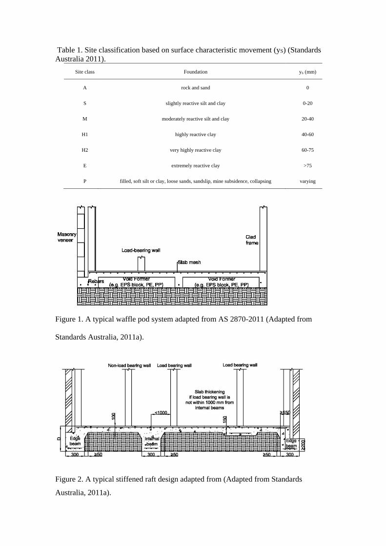
Table 1. Site classification based on surface characteristic movement (yS) (Standards
Australia 2011).
Site class Foundation yS (mm)
A rock and sand 0
S slightly reactive silt and clay 0-20
M moderately reactive silt and clay 20-40
H1 highly reactive clay 40-60
H2 very highly reactive clay 60-75
E extremely reactive clay >75
P filled, soft silt or clay, loose sands, sandslip, mine subsidence, collapsing varying
Figure 1. A typical waffle pod system adapted from AS 2870-2011 (Adapted from
Standards Australia, 2011a).
Figure 2. A typical stiffened raft design adapted from (Adapted from Standards
Australia, 2011a).

Figure 3. Footing systems using single or double block piers or pads with ground
anchors (Adapted from Manufactured Housing Research Alliance, 2002).
Figure 4. An on-ground permanent dome formwork footing system (Adapted from Kivi,
2013).
Figure 5. A footing system with bracing using metal straps (Adapted from Federal
Emergency Management Agency, 2009)..
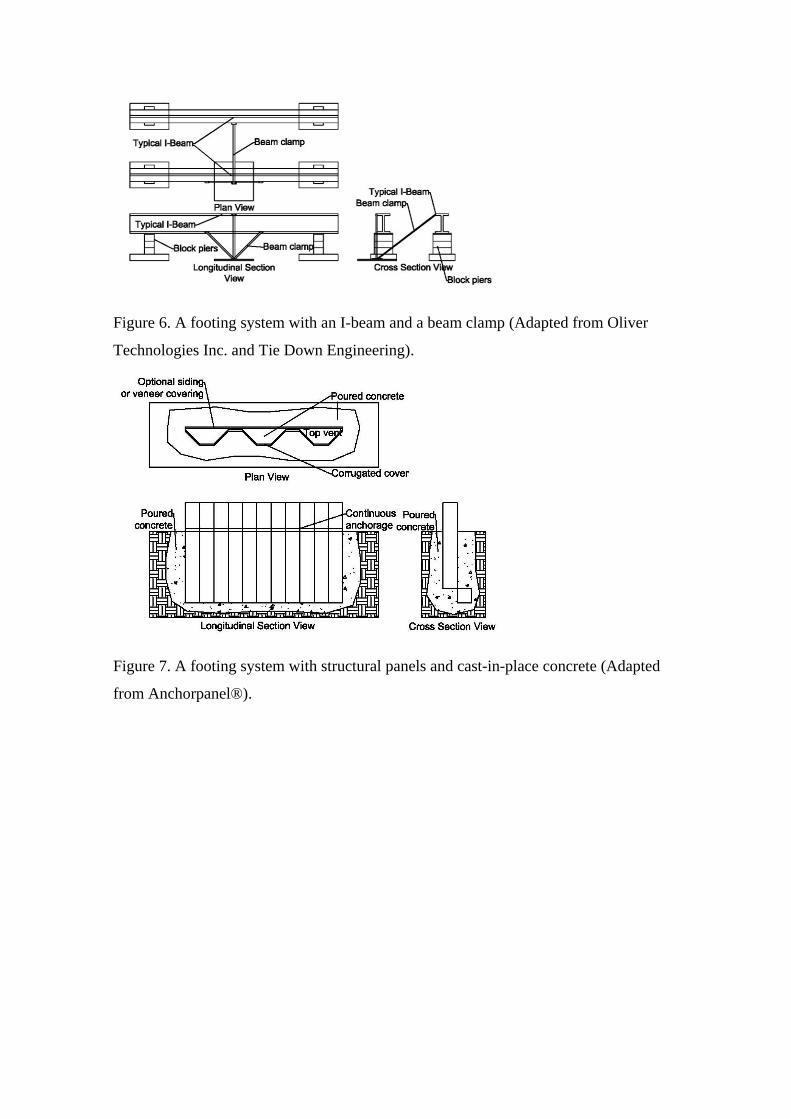
Figure 6. A footing system with an I-beam and a beam clamp (Adapted from Oliver
Technologies Inc. and Tie Down Engineering).
Figure 7. A footing system with structural panels and cast-in-place concrete (Adapted
from Anchorpanel®).
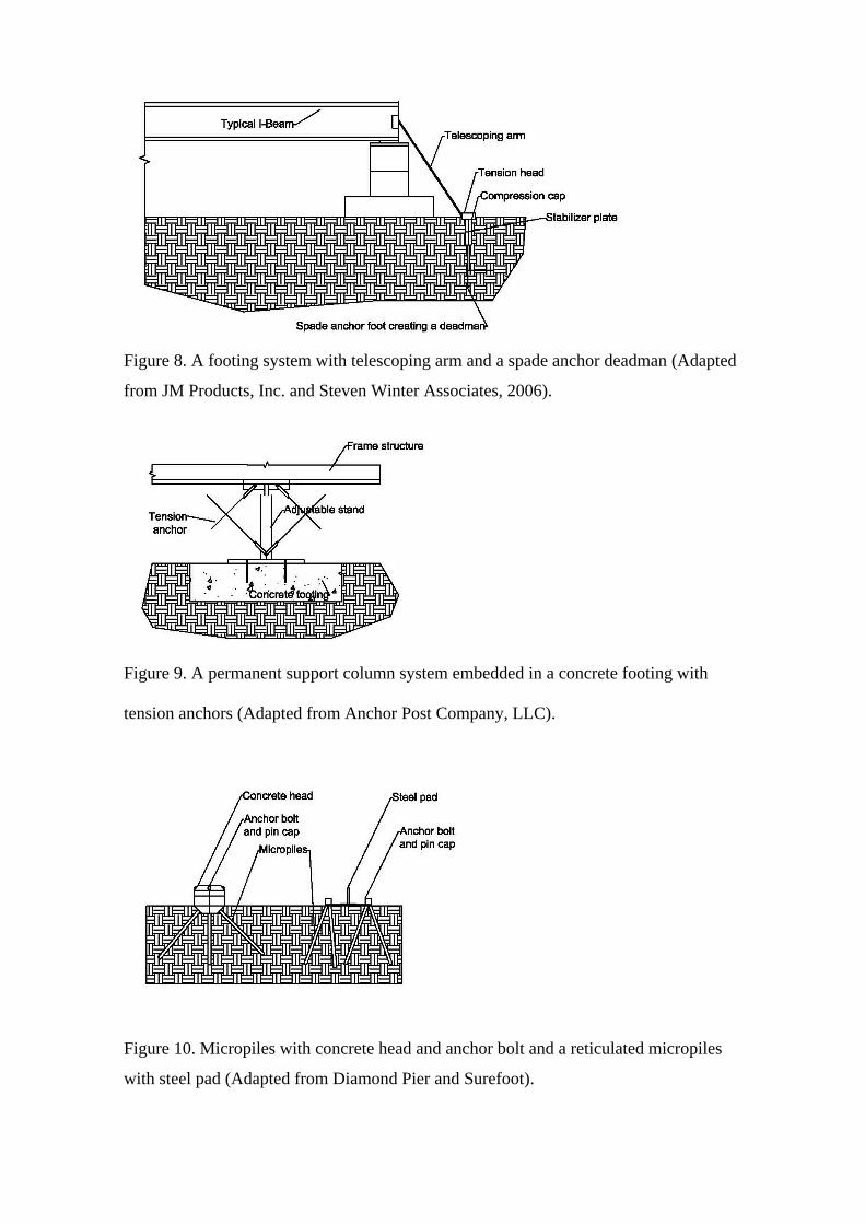
Figure 8. A footing system with telescoping arm and a spade anchor deadman (Adapted
from JM Products, Inc. and Steven Winter Associates, 2006).
Figure 9. A permanent support column system embedded in a concrete footing with
tension anchors (Adapted from Anchor Post Company, LLC).
Figure 10. Micropiles with concrete head and anchor bolt and a reticulated micropiles
with steel pad (Adapted from Diamond Pier and Surefoot).

Figure 11. Prefabricated basement foundation using an integrated wall and footing
system installed in an excavation (Adapted from Yu et al., 2008).
Figure 12. A permanent pier formwork with cast-in-place concrete (Adapted from WP
Fail Safe Form Footer).