PREDICTION OF SHEAR STRENGTH OF HIGH STRENGTH … · concrete tee beams made from high strength...
24
(2) N/mm 3 F 0.70 q (1) N/mm F 0.24 q 2 c cu u 2 c cu cr Journal of Engineering Sciences, Assiut University, Vol. 35, No.1, pp.29-52, January 2007 PREDICTION OF SHEAR STRENGTH OF HIGH STRENGTH REINFORCED CONCRETE TEE BEAMS Eng. Khaled Abdelsamee Engineer, Sohage building house organization. Dr. Mhamoud Hosni Lecturer of Structural Eng., Civil eng. Dept, Assiut University. Dr. Yehia A. Hassanean Associate Professor of Structural Eng., Civil eng. Dept, Assiut University, E-mail: [email protected] Prof. Housni M. Sogier Professor of Reinforced concrete structures, Civil eng. Dept, Assiut University (ReceivedOctober28, 2006 Accepted November 14, 2006 ) Results of an theoretical investigation of the shear strength of reinforced concrete tee beams made from high strength concrete are summarized in this paper. In addition to the effect of both flange to web width ratio of tee beams and compressive strength of the concrete, the effect of other variables such as shear span to depth ratio, percentage of both tension steel and web reinforcement were taken into consideration in predicting shear strength of high strength reinforced concrete tee beams. Finite element method was used to analyze twenty six beams subjected to two point static loading. Proposed equation to estimate the shear strength of the analyzed beams was developed. The predicated shear strengths by the proposed equation were compared with Zustty, ACI code, Egyptian code. INTRODUCTION Egyptian code of practice ECCS 203, [1], estimates the value of ultimate shear strength as 3.0 N/mm 2 for the concrete compressive strength greater than 30 MPa,. Also, the Egyptian code considers only the effect of concrete compressive strength and ignores the effect of all variables that affect the ultimate shear strength of reinforced concrete beams. The Egyptian code evaluate the values of cracking and ultimate shear strength of the reinforced concrete beams having web reinforcement by the following equations: 29
-
Upload
truongdiep -
Category
Documents
-
view
215 -
download
0
Transcript of PREDICTION OF SHEAR STRENGTH OF HIGH STRENGTH … · concrete tee beams made from high strength...
(2) N/mm 3 F
0.70 q
(1) N/mm F
0.24 q
2
c
cuu
2
c
cucr
Journal of Engineering Sciences, Assiut University, Vol. 35, No.1, pp.29-52, January 2007
PREDICTION OF SHEAR STRENGTH OF HIGH STRENGTH REINFORCED CONCRETE TEE BEAMS
Eng. Khaled Abdelsamee
Engineer, Sohage building house organization.
Dr. Mhamoud Hosni
Lecturer of Structural Eng., Civil eng. Dept, Assiut University.
Dr. Yehia A. Hassanean
Associate Professor of Structural Eng., Civil eng. Dept, Assiut
University, E-mail: [email protected]
Prof. Housni M. Sogier
Professor of Reinforced concrete structures, Civil eng. Dept,
Assiut University
(ReceivedOctober28, 2006 Accepted November 14, 2006 )
Results of an theoretical investigation of the shear strength of reinforced
concrete tee beams made from high strength concrete are summarized in
this paper. In addition to the effect of both flange to web width ratio of tee
beams and compressive strength of the concrete, the effect of other
variables such as shear span to depth ratio, percentage of both tension
steel and web reinforcement were taken into consideration in predicting
shear strength of high strength reinforced concrete tee beams. Finite
element method was used to analyze twenty six beams subjected to two
point static loading. Proposed equation to estimate the shear strength of
the analyzed beams was developed. The predicated shear strengths by the
proposed equation were compared with Zustty, ACI code, Egyptian code.
INTRODUCTION
Egyptian code of practice ECCS 203, [1], estimates the value of ultimate shear
strength as 3.0 N/mm2 for the concrete compressive strength greater than 30
MPa,. Also, the Egyptian code considers only the effect of concrete
compressive strength and ignores the effect of all variables that affect the
ultimate shear strength of reinforced concrete beams. The Egyptian code
evaluate the values of cracking and ultimate shear strength of the reinforced
concrete beams having web reinforcement by the following equations:
29
Eng. Khaled Abdelsamee, Dr. Mhamoud Hosni, Dr. Yehia A. Hassanean & Prof. Housni M. Sogier
30
(5) a
d 2500 F 1.90 )
d
a 2.5-(3.5 q
:entreinforcemshear without beams R.CFor
(4) F 3.50 a
d 2500 F 1.90 q :Or
(3) F 2 q
'
cu
'
c
'
ccr
'
ccr
Where : Fcu cube compressive strength of the concrete.
γc concrete strength reduction factor.
qcr cracking shear strength
qu ultimate shear strength
The ACI building code [2], based on experimental results of numerous beams
their compressive strength was mostly below 41.0 MPa. Previous works have
shown that the ratio of measured to predicate shear strength using ACI code
equations decreases as the concrete compressive strength increases. ACI code
underestimates the effect of longitudinal steel ratio and shear span to depth
ratio. The ACI code evaluates both the cracking and ultimate shear strength of
the beams in P.S.I. units as follows:
For R.C. beams with shear reinforcement
qu = qc + qs (6)
Where: Fc' cylinder compressive strength of the concrete.
ρ the percentage of longitudinal reinforcement.
a/d the shear span to depth ratio.
Also, Zsutty [3], proposed the following equations to evaluate both the cracking
and ultimate shear strength of the beams in P.S.I units:
Based on curve fitting of the results of twenty five High strength reinforced
beams tested under one point static loading Khaled A. M. et-al [4], proposed the
following equations to calculate the cracking shear strength in P.S.I units:
(10) a
d 583.4 F 1.365 q 3
c28r c
(9) 2.50 d
a )
a
d (F 63.40
(8) 2.50 d
a )
a
d (F 59
a/d
2.50
(7) )a
d (F 59
33.0'
c
33.0'
c
33.0'
c
u
u
cr
q
q
q
PREDICTION OF SHEAR STRENGTH OF HIGH….
31
Up to web reinforcement parameter, w fyw, equal to 5.419 kg/cm2, the ultimate
shear strength calculated by the following equation in P.S.I units:
qu = qc + w fyw (11)
For beams having web reinforcement parameter bigger than 5.419 kg/cm2 the
ultimate shear strength can be calculated from the following equation in P.S.I
units:
(12) F )f . ( 0.086 - f . 1.90 (-6.70 q q 4c28
2
ywwywwcu
The ultimate concrete shear strength qu can be expected by the following
equations in P.S.I units:
(14) 3.0 d
a 2.0 q )
a
d 2.25 0.30 ( q
(13) 2.0 d
a q )
a
d 1.4 0.75 ( q
cr c
cr c
Also, they recommended that for a/d higher or equal 3.0, the ultimate concrete
shear strength vc can be taken equal to cracking shear strength with small error
having a maximum value of 9.0 %.
For the purpose of estimating the shear strength of reinforced concrete tee
beams made from high strength concrete twenty six beams were analyzed under
two point static loading, four of them have compressive ranged from 25 to 65
MPA while the remaining twenty two beams have 80 MPa compressive
strength. In this analysis the effect of flange to web width ratio of tee beams
(B/b), concrete compressive strength Fcu, shear span to depth ratio, percentage
of longitudinal tension reinforcement and percentage of web reinforcement w
were considered. From the analysis a proposed equations were presented to
predict the shear strength of high strength reinforced concrete tee beams. Also a
comparison is made between the shear strengths calculated by available codes
and equations with that calculated by the proposed equations.
MODELING OF REINFORCED CONCRETE BEAMS BY USING FINITE ELEMENT ANALYSIS
The eight-nodded solid element will be used in this study to analyze reinforced
concrete beams. The stiffness characteristics of the elements can be determined
using the theorem of minimum potential energy, which results in the following
equation relating the element nodal forces:
{P}= [k] . {Δ} (16)
Where [k] is the element stiffness matrix and is given by:
(15) 3.0d
a for q q crc
Eng. Khaled Abdelsamee, Dr. Mhamoud Hosni, Dr. Yehia A. Hassanean & Prof. Housni M. Sogier
32
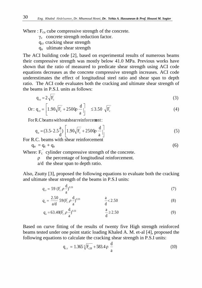
Fig.(1): Eight nodded isoparametric solid element and node numbering
Cartesian coordinate system Local coordinate system Z
(17)
Where [B] is the strain matrix and [D] is the element elasticity matrix.
In the present work, the smeared crack approach with swinging crack direction
associated with a maximum tensile strain criterion is used to simulate the
behavior of elastic concrete element. The cracks are assumed to form when the
principal strain exceeds the maximum tensile strain of concrete. The three-
dimensional eight-nodded isoparametric solid element shown in Fig. (1) has
eight nodes located at the corners and has three degrees of freedom at each
node. The linear shape functions defining the geometry and variation of
displacements within the element can be given in the form:
) tt1)(s s1)(r r1(8
1N iiii (18)
Where:
r, s and t are the natural coordinates.
ri, si and ti are the values of natural coordinates for node (i) as shown in
Fig. (1).
The geometry of the element is described as:
8
1i
i
i
i
i
z
y
x
N
z
y
x
(19)
where xi, yi and zi are the global coordinates of node (i). The relationship
between the derivatives of functions in the natural coordinates (r, s, t) and the
derivatives in Cartesian (global) coordinates (x , y z) can be established by
evaluating the Jacopian [J]. The eight nodded solid element shown in Fig. (2),
consists of eight nodes at its corners, each node has three displacements u, v
and w in directions x, y and z respectively. The shape function for
dV]B].[D.[]B[]k[ T

PREDICTION OF SHEAR STRENGTH OF HIGH….
33
Fig. (2): 8- solid element and node numbering
displacements at any point within the element is assumed to be linear function
in x, y and z and given in the form:
u = α1+ α2 x + α3 y + α4 z + α5 x y + α6 y z +α7 z x + α8 x y z (20-a)
v = α9+ α10 x + α11 y + α12 z + α13 x y + α14 y z +α15 z x + α16 x y z (20-b)
w= α17+ α18 x + α19 y + α20 z + α21 x y + α22 y z +α23 z x + α24 x y z (20-c)
Where x, y and z are the co-ordinates of the point within the element, and α1,
α2…α24 are some factors. Assuming that nodal displacements are known and
defined by the following vector {δ} where:
{δ}={u1, v1, w1, u2, v2, w2, u3, v3, w3, u4, v4, w4, u5, v5, w5, u6, v6, w6, u, v7, w7,
u8, v8, w8}T (21)
And substituting in Eqn. (20) for the element nodal point, it can be obtained
that:
{δ} = [A].{α} (22)
Where, [A] is a matrix of size 24×24 representing the coefficients resulting
from the substitution of coordinates x, y and z for the different nodal points of
the element in Eqn. (20), {α} is an unknown vector can be determined from the
relation
{α} = [A]-1
.{δ} (22)
Then, the strain at any point in the element can be given as a function of the
nodal displacements, {δ} as follows:

Eng. Khaled Abdelsamee, Dr. Mhamoud Hosni, Dr. Yehia A. Hassanean & Prof. Housni M. Sogier
34
dε dε
p
dεe
Et
Es
σy
σ
ε
dσ
Fig. (3): Stress-strain relationship for bar member of elasto-plastic material.
ε = }{ . [B] }{ . ][A . [H] }{ . ][ -1 H (23)
Therefore [B] is a matrix of 6×24 relating the strain vector {ε} at any point
within the element to the nodal displacement vector {δ}, using Castigliano’s
first theorem, the element stiffness matrix [K] is defined for elastic isotropic
element in three dimensions as:
dv [B] . [D] .[B] ]K[ T
c
c
b
b
a
a
1-TT1- ].[A dzdy dx ]H].[D.[]H[][A (24)
Where 2a, 2b and 2c are the dimensions of the element in x, y and z directions
respectively. The derivation of the stiffness matrix is the same for either
cracked or uncracked element, the only difference between the two cases are the
choosing of the elasticity matrix [D]. For the cracked element either the secant
stiffness matrix or the tangential stiffness matrix is used, where the secant
stiffness matrix is given in the form:
c
c
b
b
a
a
1-
s
TT1-
s ].[A dzdy dx ]H].[D.[]H[][A ]K[ (25)
and the tangential stiffness matrix is given in form:
c
c
b
b
a
a
1-
t
TT1-
t ].[A dzdy dx ]H].[D.[]H[][A ]K[ (26)
ELASTO-PLASTIC STIFFNESS MATRIX OF THE BAR MEMBER
The stress- strain relationship for a bar element of elasto-plastic material is
shown in Fig. (3). the bar element initially deforms elastically with axial
rigidity EsAb until the yield stress, where Es, Ab are young’s modules of
elasticity of steel and the cross sectional area of the bar. By increasing the load
PREDICTION OF SHEAR STRENGTH OF HIGH….
35
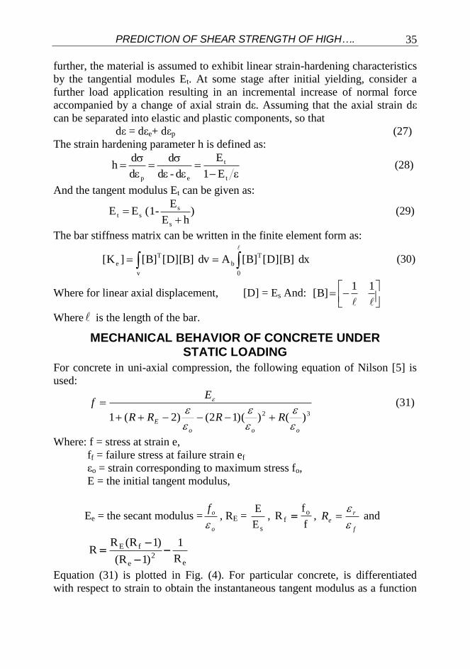
further, the material is assumed to exhibit linear strain-hardening characteristics
by the tangential modules Et. At some stage after initial yielding, consider a
further load application resulting in an incremental increase of normal force
accompanied by a change of axial strain dε. Assuming that the axial strain dε
can be separated into elastic and plastic components, so that
dε = dεe+ dεp (27)
The strain hardening parameter h is defined as:
t
t
ep E1
E
d -d
d
d
d h (28)
And the tangent modulus Et can be given as:
)hE
E-(1 E E
s
sst
(29)
The bar stiffness matrix can be written in the finite element form as:
v 0
T
b
T
e dx ]B][D[]B[Adv ]B][D[]B[]K[
(30)
Where for linear axial displacement, [D] = Es And:
11 ]B[
Where is the length of the bar.
MECHANICAL BEHAVIOR OF CONCRETE UNDER STATIC LOADING
For concrete in uni-axial compression, the following equation of Nilson [5] is
used:
32 )())(12()2(1ooo
E RRRR
Ef
(31)
Where: f = stress at strain e,
ff = failure stress at failure strain ef
εo = strain corresponding to maximum stress fo,
E = the initial tangent modulus,
Ee = the secant modulus =o
of
, RE =
sE
E,
f
fR o
f , f
reR
and
e
2e
fE
R
1
)1R(
)1R(RR
Equation (31) is plotted in Fig. (4). For particular concrete, is differentiated
with respect to strain to obtain the instantaneous tangent modulus as a function

Eng. Khaled Abdelsamee, Dr. Mhamoud Hosni, Dr. Yehia A. Hassanean & Prof. Housni M. Sogier
36
of concrete strain. For concrete in uni-axial tension, it assumed that linear
behavior is obtained up to failure.
Vecchio [6] developed a nonlinear finite element procedure to predict the
response of reinforced concrete membrane elements based on a secant stiffness
formulation. The stress in the concrete and reinforcement are determined from
the strains according to the modified compression field theory. The principal
compressive stress in the concrete Fc is:
2
oo
max cc 2FF
(32)
Where: Fc max
o
28c
/34.08.0
F
STRESS-STRAIN CURVE FOR LOW, NORMAL AND HIGH STRENGTH CONCRETE:
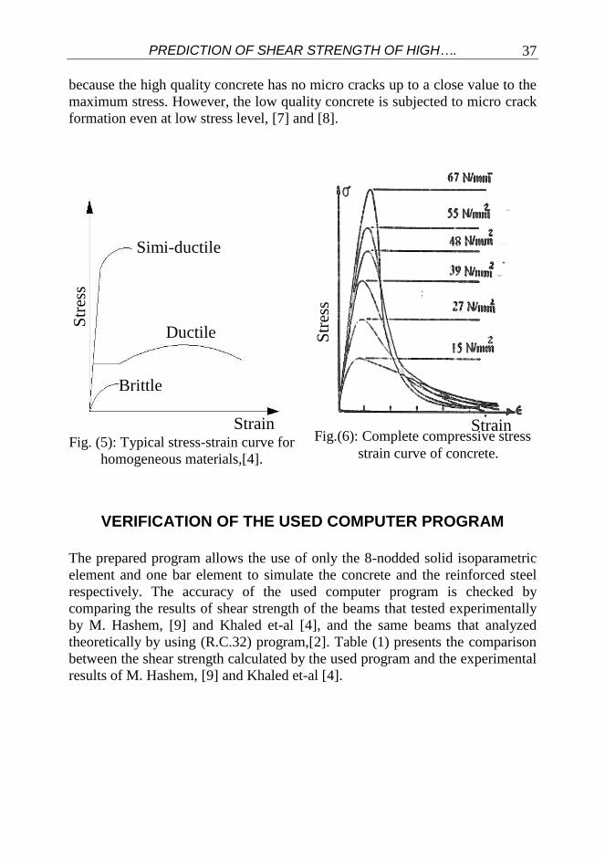
Fig.(5) illustrate the stress-strain relationship for the homogeneous material
under tension. The behavior of concrete is completely different from that of the
brittle homogeneous material; the residual strain of the concrete is due to
cracked formation. The stress-strain curve for concrete of low, normal and high
strength have the same shape. In Fig. (6) a high strength concrete behaves in a
linear fashion to a relatively higher level than the low strength concrete. This
0 Unit strain ε
Fig. (4): compressive stress-strain curve for concrete
1000
2000
3000
4000
5000 C
om
pre
ssiv
e st
ress
(p
si)
0.001 0.002
32 )())(12()2(1ooo
E RRRR
Ef
PREDICTION OF SHEAR STRENGTH OF HIGH….
37
because the high quality concrete has no micro cracks up to a close value to the
maximum stress. However, the low quality concrete is subjected to micro crack
formation even at low stress level, [7] and [8].
VERIFICATION OF THE USED COMPUTER PROGRAM
The prepared program allows the use of only the 8-nodded solid isoparametric
element and one bar element to simulate the concrete and the reinforced steel
respectively. The accuracy of the used computer program is checked by
comparing the results of shear strength of the beams that tested experimentally
by M. Hashem, [9] and Khaled et-al [4], and the same beams that analyzed
theoretically by using (R.C.32) program,[2]. Table (1) presents the comparison
between the shear strength calculated by the used program and the experimental
results of M. Hashem, [9] and Khaled et-al [4].
Simi-ductile
Ductile
Brittle
Str
ess
Fig. (5): Typical stress-strain curve for
homogeneous materials,[4].
Fig.(6): Complete compressive stress
strain curve of concrete.
Strain
Str
ess
Strain
Eng. Khaled Abdelsamee, Dr. Mhamoud Hosni, Dr. Yehia A. Hassanean & Prof. Housni M. Sogier
38
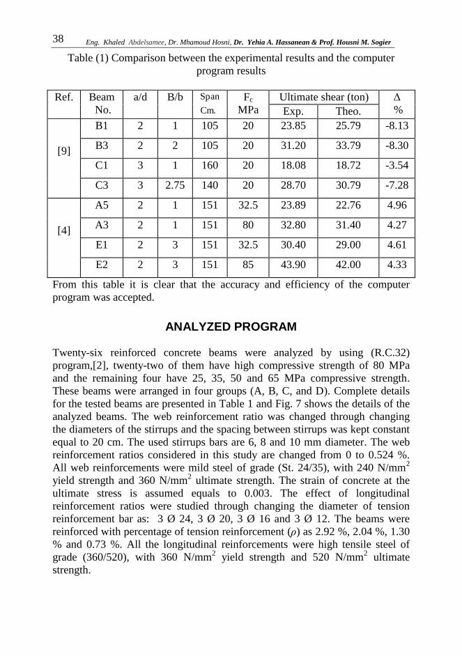
Table (1) Comparison between the experimental results and the computer
program results
Ref. Beam
No.
a/d B/b
.Cm
Span Fc
MPa
Ultimate shear (ton) Δ
% Exp. Theo.
[9]
B1 2 1 105 20 23.85 25.79 -8.13
B3 2 2 105 20 31.20 33.79 -8.30
C1 3 1 160 20 18.08 18.72 -3.54
C3 3 2.75 140 20 28.70 30.79 -7.28
[4]
A5 2 1 151 32.5 23.89 22.76 4.96
A3 2 1 151 80 32.80 31.40 4.27
E1 2 3 151 32.5 30.40 29.00 4.61
E2 2 3 151 85 43.90 42.00 4.33
From this table it is clear that the accuracy and efficiency of the computer
program was accepted.
ANALYZED PROGRAM
Twenty-six reinforced concrete beams were analyzed by using (R.C.32)
program,[2], twenty-two of them have high compressive strength of 80 MPa
and the remaining four have 25, 35, 50 and 65 MPa compressive strength.
These beams were arranged in four groups (A, B, C, and D). Complete details
for the tested beams are presented in Table 1 and Fig. 7 shows the details of the
analyzed beams. The web reinforcement ratio was changed through changing
the diameters of the stirrups and the spacing between stirrups was kept constant
equal to 20 cm. The used stirrups bars are 6, 8 and 10 mm diameter. The web
reinforcement ratios considered in this study are changed from 0 to 0.524 %.
All web reinforcements were mild steel of grade (St. 24/35), with 240 N/mm2
yield strength and 360 N/mm2 ultimate strength. The strain of concrete at the
ultimate stress is assumed equals to 0.003. The effect of longitudinal
reinforcement ratios were studied through changing the diameter of tension
reinforcement bar as: 3 Ø 24, 3 Ø 20, 3 Ø 16 and 3 Ø 12. The beams were
reinforced with percentage of tension reinforcement (ρ) as 2.92 %, 2.04 %, 1.30
% and 0.73 %. All the longitudinal reinforcements were high tensile steel of
grade (360/520), with 360 N/mm2 yield strength and 520 N/mm
2 ultimate
strength.

PREDICTION OF SHEAR STRENGTH OF HIGH….
39
Table (2) Details of the analyzed beams
Group Beam a/d B/b Le (cm) Stirrups Main steel Fc28 (MPa)
A
A1-1 1 3 93 5 Ø 8 3 Φ 24 800
A1-2 2 3 186 5 Ø 8 3 Φ 24 800
A1-3 3 3 279 5 Ø 8 3 Φ 24 800
A1-4 4 3 372 5 Ø 8 3 Φ 24 800
A2-2 2 3 186 5 Ø 8 3 Φ 24 250
A3-1 2 3 186 5 Ø 8 3 Φ 24 350
A3-2 2 3 186 5 Ø 8 3 Φ 24 500
A3-3 2 3 186 5 Ø 8 3 Φ 24 650
B
B1-1 2 1 186 5 Ø 8 3 Φ 24 800
B1-2 2 2 186 5 Ø 8 3 Φ 24 800
B1-3 2 4 186 5 Ø 8 3 Φ 24 800
B1-4 4 1 372 5 Ø 8 3 Φ 24 800
B1-5 4 2 372 5 Ø 8 3 Φ 24 800
B1-6 4 4 372 5 Ø 8 3 Φ 24 800
C
C1-1 2 3 186 NO 3 Φ 24 800
C1-2 2 3 186 5 Ø 6 3 Φ 24 800
C1-3 2 3 186 5 Ø 10 3 Φ 24 800
C1-4 4 3 372 NO 3 Φ 24 800
C1-5 4 3 372 5 Ø 6 3 Φ 24 800
C1-6 4 3 372 5 Ø 10 3 Φ 24 800
D
D1-1 2 3 186 5 Ø 8 3 Φ 20 800
D1-2 2 3 186 5 Ø 8 3 Φ 16 800
D1-3 2 3 186 5 Ø 8 3 Φ 12 800
D1-4 4 3 372 5 Ø 8 3 Φ 20 800
D1-5 4 3 372 5 Ø 8 3 Φ 16 800
D1-6 4 3 372 5 Ø 8 3 Φ 12 800

Eng. Khaled Abdelsamee, Dr. Mhamoud Hosni, Dr. Yehia A. Hassanean & Prof. Housni M. Sogier
40
The modulus of elasticity of concrete depends on its compressive strength, and
its value is calculated by using the Egyptian code ECCS203-2001, [1], for
normal grade of compressive strength concrete of 25 N/mm2 and 35 N/mm
2.
While for high compressive strength concrete 50, 65 and 80 N/mm2, the
modulus of elasticity is calculated using the following equation:
.N/mm 6900F3320Ec 228c (33)
a) Rectangular cross section B/b = 1 b) T – section with B/b = 2
e
c) T – section with B/b = 3 d) T – section with B/b = 4
Fig. (7-b): Cross sections of the analyzed beams.
Fig. (8): Details of the analyzed beams.
PREDICTION OF SHEAR STRENGTH OF HIGH….
41
RESULTS AND DISCUSSION
PATTERNS OF CRACKS AND MODES OF FAILURE
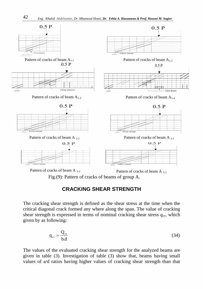
For both short and slender beams, firstly in beams having rectangular cross
section there is a diagonal crack was formed clearly along the total depth of the
beam, but in T-section beams the diagonal crack formed along the beam web
only and don’t subsist to the flange. The width and the length of the diagonal
crack depend on the width of the flange as shown in Fig (9). The width and the
length of the diagonal crack depend on the width of the flange. The width and
the length of the diagonal crack depends on the width of the flange, also another
vertical cracks is formed at the midspan of slender beams only, as shown in Fig
(9).
Presence of stirrups has a considerable effect on pattern of cracks and the final
mode of failure. The importance of stirrups already appeared when the first
inclined crack occurred, that as the crack opens, the stirrups help to contain the
crack, limiting its propagation and keeping its width smaller than beams
without stirrups. Another secondary diagonal cracks formed approximately
parallel to the direction of the first inclined crack. The amount of longitudinal
steel ratio has slight effect on final mode of failure as the longitudinal steel ratio
increases, the number of cracks decreases and hence affects the inclination of
the main crack. The concrete compressive strength has a considerable effect on
pattern of cracks, especially for beams having higher longitudinal steel ratios.
For beams made from high-strength concrete, several flexural cracks developed
than that for beams made from normal strength concrete. The inclination of the
main crack does not affect by the concrete strength. Presence of beam flange
has a considerable effect on pattern of cracks and the final mode of failure,
especially for beams made from high-strength concrete and having small values
of a/d ratio.
Eng. Khaled Abdelsamee, Dr. Mhamoud Hosni, Dr. Yehia A. Hassanean & Prof. Housni M. Sogier
42
Pattern of cracks of beam A1-1 Pattern of cracks of beam A1-2
Pattern of cracks of beam A 3-2
Pattern of cracks of beam A 3-3
Pattern of cracks of beam A 2-2
Pattern of cracks of beam A 3-1
Fig.(9): Pattern of cracks of beams of group A.
Pattern of cracks of beam A1-3 Pattern of cracks of beam A1-4
CRACKING SHEAR STRENGTH
The cracking shear strength is defined as the shear stress at the time when the
critical diagonal crack formed any where along the span. The value of cracking
shear strength is expressed in terms of nominal cracking shear stress qcr, which
given by as following:
d.b
Qq cr
cr (34)
The values of the evaluated cracking shear strength for the analyzed beams are
given in table (3). Investigation of table (3) show that, beams having small
values of a/d ratios having higher values of cracking shear strength than that

PREDICTION OF SHEAR STRENGTH OF HIGH….
43
having higher values of a/d ratios, this result agree with [4], [9]. For short
beams the a/d ratios is more effective in cracking shear strength than other
variables. The cracking shear strength decreases as a/d ratio increases. This is
because large values of a/d means high values of bending moment in shear
span, thus the depth of penetration of flexural cracks increases, and hence the
flexural stresses near the crack tip increase. By increasing a/d, the probability
grows that a flexural crack will develop clearly. The cracking shear strength of
beams having a/d ratios equals to 1.00 is 1.91 times of the cracking shear
strength of beams having a/d =4.0.
The results show that, beams having high flange to web width ratio, have higher
values of cracking shear strength than beams having low B/b ratios or beams
having rectangular cross section. The flange to web width ratio have
considerable effect on the cracking shear strength of slender beams and a slight
effect on cracking shear strength of short beams. ,
Generally, increasing tension steel ratio increases cracking shear strength. It is
clear that, for short high strength concrete T-beams, increasing tension steel
ratio from 0.73 % to 2.92 % increases the cracking shear strength by 15.0 %.
Also, for slender high strength T-beams, increasing of tension steel ratio from
0.73 % to 2.92 % increases the cracking shear strength by 5.10 %. The
longitudinal steel ratio has a pronounced effect on the basic shear transfer
mechanisms.
As the concrete compressive strength increases, the cracking shear strength of
the analyzed beams increases. Increase of concrete compressive strength for T-
beams having B/b equals to 3.00 from 25 to 80 MPa, increasing the cracking
shear strength by 56.51 % for a/d ratio equals to 2.0. Concrete compressive
strength is more effective for slender beams than that short beams. The cracking
shear strength decreases slightly as a/d increases from 1.00 to 3.00, and
increased sharply as a/d increased from 3.00 to 4.00. The increas in cracking
shear strength of slender T-beams made from high strength concrete, (a/d = 4,
Fc28 = 80) was the highest one due to the fact that, the area of compression zone
was higher because the high strength concrete beams was under reinforced
sections. From table (3), it appears that the stirrups have no effect on cracking
shear strength for high strength concrete for both slender and short beams.

Eng. Khaled Abdelsamee, Dr. Mhamoud Hosni, Dr. Yehia A. Hassanean & Prof. Housni M. Sogier
44
Table (3): Cracking and ultimate shear strength of analyzed beams
Beam a/d B/b ρ% ρw.Fyw Fc28
MPa
qcr
kg/cm2
qu
kg/cm2
Mode of
failure
A1-1 1 3 2.92 8.04 80 9.89 41.6 D.T
A1-2 2 3 2.92 8.04 80 8.17 38.36 D.T
A1-3 3 3 2.92 8.04 80 6.37 28.42 S.C
A1-4 4 3 2.92 8.04 80 5.18 21.35 F.T
A2-2 2 3 2.92 8.04 25 5.02 25.67 D.T
A3-1 2 3 2.92 8.04 35 6.9 29.00 D.T
A3-2 2 3 2.92 8.04 50 7.6 31.5 D.T
A3-3 2 3 2.92 8.04 65 7.8 34.2 D.T
B1-1 2 1 2.92 8.04 80 7.16 30.53 S.C
B1-2 2 2 2.92 8.04 80 7.56 37.62 S.C
B1-3 2 4 2.92 8.04 80 8.45 41.26 S.C
B1-4 4 1 2.92 8.04 80 3.13 17.60 S.C
B1-5 4 2 2.92 8.04 80 4.10 20.70 F.T
B1-6 4 4 2.92 8.04 80 5.43 22.00 F.t
C1-1 2 3 2.92 0.00 80 8.10 31.40 S.C
C1-2 2 3 2.92 4.51 80 8.16 37.16 S.C
C1-3 2 3 2.92 12.55 80 8.16 39.20 S.C
C1-4 4 3 2.92 0.00 80 5.07 19.24 S.C
C1-5 4 3 2.92 4.51 80 5.13 20.51 F.T
C1-6 4 3 2.92 12.55 80 5.22 21.71 F.T
D1-1 2 3 2.04 8.04 80 7.74 37.80 S.C
D1-2 2 3 1.30 8.04 80 7.32 35.60 S.C
D1-3 2 3 0.73 8.04 80 7.10 35.30 S.C
D1-4 4 3 2.04 8.04 80 5.06 20.81 S.C
D1-5 4 3 1.30 8.04 80 4.97 20.33 S.C
D1-6 4 3 0.73 8.04 80 4.93 19.36 F.T
ULTIMATE SHEAR STRENGTH
The ultimate shear strength means the maximum value of shear stress that can
be sustained by the beam cross-section. The value of ultimate shear strength
conventionally expressed in terms of nominal ultimate shear stress vu, which is
given by:
(35) d b
Q q u
u
PREDICTION OF SHEAR STRENGTH OF HIGH….
45
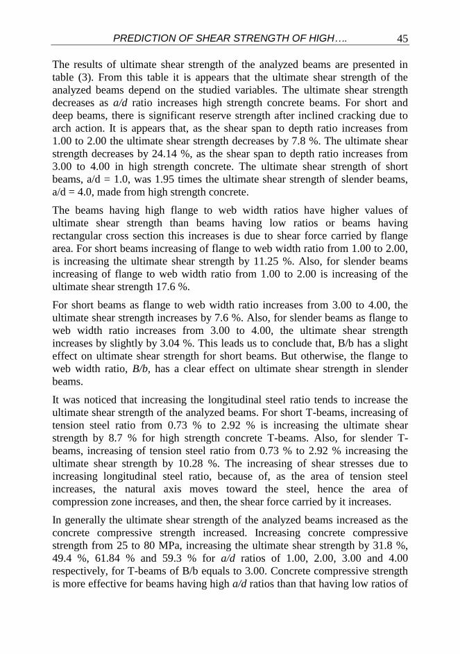
The results of ultimate shear strength of the analyzed beams are presented in
table (3). From this table it is appears that the ultimate shear strength of the
analyzed beams depend on the studied variables. The ultimate shear strength
decreases as a/d ratio increases high strength concrete beams. For short and
deep beams, there is significant reserve strength after inclined cracking due to
arch action. It is appears that, as the shear span to depth ratio increases from
1.00 to 2.00 the ultimate shear strength decreases by 7.8 %. The ultimate shear
strength decreases by 24.14 %, as the shear span to depth ratio increases from
3.00 to 4.00 in high strength concrete. The ultimate shear strength of short
beams, a/d = 1.0, was 1.95 times the ultimate shear strength of slender beams,
a/d = 4.0, made from high strength concrete.
The beams having high flange to web width ratios have higher values of
ultimate shear strength than beams having low ratios or beams having
rectangular cross section this increases is due to shear force carried by flange
area. For short beams increasing of flange to web width ratio from 1.00 to 2.00,
is increasing the ultimate shear strength by 11.25 %. Also, for slender beams
increasing of flange to web width ratio from 1.00 to 2.00 is increasing of the
ultimate shear strength 17.6 %.
For short beams as flange to web width ratio increases from 3.00 to 4.00, the
ultimate shear strength increases by 7.6 %. Also, for slender beams as flange to
web width ratio increases from 3.00 to 4.00, the ultimate shear strength
increases by slightly by 3.04 %. This leads us to conclude that, B/b has a slight
effect on ultimate shear strength for short beams. But otherwise, the flange to
web width ratio, B/b, has a clear effect on ultimate shear strength in slender
beams.
It was noticed that increasing the longitudinal steel ratio tends to increase the
ultimate shear strength of the analyzed beams. For short T-beams, increasing of
tension steel ratio from 0.73 % to 2.92 % is increasing the ultimate shear
strength by 8.7 % for high strength concrete T-beams. Also, for slender T-
beams, increasing of tension steel ratio from 0.73 % to 2.92 % increasing the
ultimate shear strength by 10.28 %. The increasing of shear stresses due to
increasing longitudinal steel ratio, because of, as the area of tension steel
increases, the natural axis moves toward the steel, hence the area of
compression zone increases, and then, the shear force carried by it increases.
In generally the ultimate shear strength of the analyzed beams increased as the
concrete compressive strength increased. Increasing concrete compressive
strength from 25 to 80 MPa, increasing the ultimate shear strength by 31.8 %,
49.4 %, 61.84 % and 59.3 % for a/d ratios of 1.00, 2.00, 3.00 and 4.00
respectively, for T-beams of B/b equals to 3.00. Concrete compressive strength
is more effective for beams having high a/d ratios than that having low ratios of
Eng. Khaled Abdelsamee, Dr. Mhamoud Hosni, Dr. Yehia A. Hassanean & Prof. Housni M. Sogier
46
a/d. Concrete compressive strength is more effective than shear span to depth
ratio in resisting shear stresses.
Investigation of table (3) show that the ultimate shear strength of beams having
web reinforcement is higher than those without web reinforcement and the
shear strength is increasing as the web reinforcement parameter increases. As
the web reinforcement parameter increased from zero to 12.55 kg/cm2, the
ultimate shear strength increased by 24.84% and 12.80% for short and slender
T-beams respectively. It is clearly that stirrups not only carry shear themselves
but also enhance the strength of the other shear transfer mechanisms. The
stirrups provide support for the longitudinal steel and prevent the bars from
splitting from the surrounding concrete, at the same time, the stirrups held to
contain the crack, limiting its propagation and keeping its width small. Stirrups
also increase the strength of compression concrete by providing confinement.
Although stirrups don’t affect the diagonal cracking load, they enhance the
concrete contribution by increasing the capacity of the different shear transfer
mechanism.
PROPOSED EQUATION FOR ESTIMATING SHEAR STRENGTH FOR R.C. T-BEAMS
EQUATIONS FOR CRACKING SHEAR STRENGTH
The examination of the cracking shear strength indicates that, the shearing
stresses at cracking level depends mainly on shear span to depth ratio, a/d,
percentage of main steel ratio, ρ, and flange to web width ratio, B/b, for a
certain grade of concrete.
The obtained values of initial cracking shear stress, are statistically treated
using the available data and may be best fitted and writen as the following form
in S.I unites:
2d
a F715.0S18.36q 3
28ccr (36)
4d
a 2 F4.0S413.1q 3
28c
2
cr (37)
The values of cracking shear strength by using above equations are represented
in Fig. (10), in addition to the results of cracking shear strength.

PREDICTION OF SHEAR STRENGTH OF HIGH….
47
EQUATIONS FOR ULTIMATE SHEAR STRENGTH:
Also, the examination of the values of ultimate shear strength of the analyzed
T-beams indicates that, the ultimate shearing stresses depends mainly on web
reinforcement factor, shear span to depth ratio, percentage of main steel ratio,
and flange to web width ratio for certain grade of concrete. The obtained values
of ultimate shear stress, are statistically treated using the available data and may
be best fitted and written as the following form:
FOR BEAMS WITH WEB REINFORCEMENT:
2d
a FF.212.0)
b
B
a
d100(08.2qq 28cywwcru (38)
4d
a 2 FF.0785.0)
b
B
a
d100(92.1qq 3
28cywwcru (39)
FOR BEAMS WITHOUT WEB REINFORCEMENT:
S68.39F47.5qq 428ccru
(40)
qu-2
y = 1.0009 x
0
10
20
30
40
50
0 10 20 30 40 50
Fig. (11): The relationship between
ultimate values of shear strength of
analyzed beams and that estimated by
eqn. (37) to (39).
2u1u q 0009.1q
qcr-2
(Kg/cm2)
qu
-1
qcr-1
Fig. (10): The relationship between
cracking values of shear strength of
analyzed beams and that estimated by
eqns. (35) and (36).
y = 1.0006x
0
2
4
6
8
10
12
0 2 4 6 8 10 12
2cr1cr q 0006.1q

Eng. Khaled Abdelsamee, Dr. Mhamoud Hosni, Dr. Yehia A. Hassanean & Prof. Housni M. Sogier
48
The values of ultimate shear strength by using above equations in addition to
the results of ultimate shear strength are represented in Fig. (11).
COMPARISON OF SHEAR STRENGTH OF THE TESTED BEAMS WITH SOME AVAILABLE AND
IMPORTANT EQUATIONS
Many equations have bean derived for calculating the cracking and ultimate
shear strength in reinforced concrete beams. A comparison between the
predicated values of shear strength by using the proposed equations and those
proposed in ACI-code, Zsutty’s equation, and Egyptian code equations are
presented.
Cracking Shear Strength Egyptian Code Equations The cracking value of shear strength for T-beams having different grades of
concrete compressive strength can be given by equation (1). It is appears that in
this equation the cracking shear strength is depending on concrete compressive
strength only.
Ultimate Shear Strength American Concrete Institute In the ACI. Code, the value of ultimate shear strength, qu, is calculated from
equations (5) and (6).
Zsutty’s Equation:
Zsutty derived equations (8) and (9) for predicting the ultimate shear strength,
qu.
Egyptian Code Equation In the ECCS 203-2001 Code, the value of ultimate shear strength, qu, is
calculated from equation (2). The obtained values of qu from proposed equation
and predicted values by ACI Code and Zsutty’s equations are given in table (4)
and Fig. (11). Also compression between the different values of the ultimate
cracking shear strength, qu is presented in the same table.
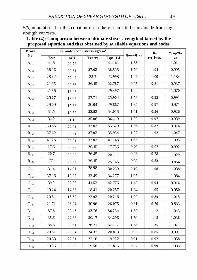
From table (4) and Figs. (11), its appears that ACI. Code equation is
conservative for most values that it underestimates the importance of both shear
spane to depth ratio, and longitudinal steel ratio, flange to web width ratio.
Also, it can notice that Zsutty’s equations describe ultimate shear strength for
the test results with the maximum error for low values of concrete compressive
strength about 4.29 %. Comparing the test results by the predicted results by
ECCS 203, equations. It is appears that ECCS 203 equation dose not estimated
the ultimate shear strength that it has a constant value of ultimate shear strength
equals 28.4 Kg/cm2 for beams having Fc28 equals to 250 Kg/cm
2.
The ECCS 203, Code equation not take into consideration the effect of shear
span to depth ratio, a/d, longitudinal steel ratio, ρ, flange to web width ratio,
PREDICTION OF SHEAR STRENGTH OF HIGH….
49
B/b, in additional to this equation not to be virtuous to beams made from high
strength concrete.
Table (4): Comparison between ultimate shear strength obtained by the
proposed equation and that obtained by available equations and codes
Beam
No.
Ultimate shear stress kg/cm2
qu test/qACI
qu
test/qzsutty
vu eqn/qu
test Test ACI Zsutty Eqn. 3.4
A1-1 41.6 22.76 - 41.161 1.83 - 1.011
A1-2 38.36 22.51 37.02 38.538 1.70 1.04 0.995
A1-3 28.42 22.42 28.3 23.998 1.27 1.00 1.184
A1-4 21.35 22.38 26.45 22.787 0.95 0.81 0.937
A2-1 31.56 16.48 - 29.497 1.92 - 1.070
A2-2 25.67 16.22 27.71 25.904 1.58 0.93 0.991
A3-1 29.00 17.68 30.04 29.867 1.64 0.97 0.971
A3-2 31.5 19.52 32.82 34.018 1.61 0.96 0.926
A3-3 34.2 21.10 35.08 36.419 1.62 0.97 0.939
B1-1 30.53 22.51 37.02 33.329 1.36 0.82 0.916
B1-2 37.62 22.51 37.02 35.934 1.67 1.02 1.047
B1-3 41.26 22.51 37.02 41.143 1.83 1.11 1.003
B1-4 17.6 22.38 26.45 17.736 0.79 0.67 0.992
B1-5 20.7 22.38 26.45 20.111 0.93 0.78 1.029
B1-6 22 22.38 26.45 25.765 0.98 0.83 0.854
C1-1 31.4 14.51 28.98 30.239 2.16 1.08 1.038
C1-2 37.16 19.02 33.49 34.277 1.95 1.11 1.084
C1-3 39.2 27.07 41.53 42.776 1.45 0.94 0.916
C1-4 19.24 14.38 18.41 20.257 1.34 1.05 0.950
C1-5 20.51 18.89 22.92 20.216 1.09 0.89 1.015
C1-6 21.71 26.94 30.96 26.075 0.81 0.70 0.833
D1-1 37.8 22.43 33.76 36.234 1.69 1.12 1.043
D1-2 35.6 22.36 30.17 34.296 1.59 1.18 1.038
D1-3 35.3 22.31 26.21 32.777 1.58 1.35 1.077
D1-4 20.81 22.34 24.37 20.873 0.93 0.85 0.997
D1-5 20.33 22.31 22.10 19.222 0.91 0.92 1.058
D1-6 19.36 22.28 19.58 17.875 0.87 0.99 1.083
Eng. Khaled Abdelsamee, Dr. Mhamoud Hosni, Dr. Yehia A. Hassanean & Prof. Housni M. Sogier
50
CONCLUSION
1- The final mode of, initial cracking and ultimate shear strength of high
strength concrete T-beams are mainly affected by shear span to depth ratio,
flange to web width ratio, longitudinal steel ratio, and concrete
compressive strength.
2- Web reinforcement has no effect on the cracking shear strength of T-beams
made from high strength concrete.
3- For T-beams failing in shear, the value of cracking shear strength, qcr, in S.I
unites can predicted using the following equations:
2d
a F715.0S18.36q 3
28ccr
4d
a 2 F4.0S413.1q 3
28c
2
cr
Where S is dimension less factor = (d/a) ×(B/b)
2d
a FF.212.0)
b
B
a
d100(08.2qq 28cywwcru
4- Ultimate shear strength of reinforced concrete T-beams is directly
proportional to cracking shear strength and web reinforcement factor.
5- For T-beams that failing in shear under static loading, the value of
ultimate shear strength in S.I. units can predicted using the following
equations:
For beams with web reinforcement :
4d
a 2 FF.0785.0)
b
B
a
d100(92.1qq 3
28cywwcru
For beams without web reinforcement:
S68.39F47.5qq 428ccru
6- The values of ultimate shear strength of analyzed beams show
remarkable difference in comparison with the corresponding
recommended values given in the ACI. Code equation.
7- The predicted values of ultimate shear strength by Zsutty’s equation
slightly agree with that achieved by analyzed beams.
8- The values of cracking and ultimate shear strength of analyzed beams
show disagreement with the corresponding values of adopted values of
Egyptian code equations.

PREDICTION OF SHEAR STRENGTH OF HIGH….
51
REFERENCES
[1] Egyptian code of concrete practice, 2001.
[2] M. H. Mansour, “Structural Analysis of R.C. Beams In Three
Dimensions”, M. Sc., Thesis, Assiut University, Egypt, 1999
[3] ACI manual of concrete practice, 1994.
[4] Zsutty T., (1971), “Shear strength prediction for separate categories
of simple beam tests” ACI Journal Vol. 68, No. 2, February.
[5] Khaled A. Mahmoud, Kamal A. Assaf, Yehia H. Hassanean and A.
Megahid "predection of shear strength of high strength reinforced
concrete tee beams."
[6] Nilson, A.H., “Nonlinear Analysis of Reinforced Concrete bythe
Finite Element Method”, ACI Journal Vol. 65 No. 757-766,
September 1968.
[7] Vechio, F. J., “Nonlinear Finite Element Analysis of Reinforced
Concrete Members”, ACI Structural Journal, Vol. 86, No. 4,
January-February 1989.
[8] Aly A.G. and Soghair, H.M., “Analysis of R.C. Beams”, Eng., Res.
Journal, Vol. 48, May 1996.
[9] Chen, W. “Plasticity in Reinforced Concrete”, MC. Graw-Hill Bock
Co. 1982.
[10] M. M. Hashem, “Shear Response of Reinforced Concrete T-Beams
to Static and Repeated Loads” M. Sc., Thesis, Assiut University,
Egypt, 1979.
[11] Kamal A. Assaf, (1986) The “Behavior of R.C. beams of L-Section
under static and repeated loads” M.Sc. Assiut University.
[12] Kim J. K. and Park Y. D., (1994), “Shear strength of reinforced high
strength concrete
beams without web reinforcement “ Magazine of concrete research,
Vol. 46, No. 166, March.
[13] Salandra M. A. and Ahmed S. H., (1989), ”Shear capacity of
reinforced concrete lightweight high strength concrete beams” ACI
journal, Vol. 86, No. 6, November-December.
[14] Sung-Woo S. Kwang-Soo L. Jung-Moon and S. K. Ghosh, (1999), “Shear strength of reinforced high strength concrete beams with
shear span to depth ratio between 1.50 and 2.50” ACI Journal Vol.
96, No. 5, July-August.
[15] Yoon, Y. S., Cook W. D. and Mitchell D., (1996), “Minimum shear
reinforcement in normal, medium and high strength concrete
beams” ACI Journal Vol. 93, No. 5, September-October.

Eng. Khaled Abdelsamee, Dr. Mhamoud Hosni, Dr. Yehia A. Hassanean & Prof. Housni M. Sogier
52
[16] Zhang J. P., (1997), « Diagonal cracking and shear strength of
reinforced concrete beams” Magazine of concrete research, Vol. 49,
No. 178, March.
سلوك القص للكمرات الخرسانية المسلحة ذات المقاومة العالية
ةتحت تأثير األحمال االستاتيكي Tذات مقطع علي شكل حرف قتهرررل ال رررر ل ذهرررما ها الغرررمن هرررا برررها التنررر برررت الرررؤ تقي همرررق ل ؤ تررر ت ررر ه
تالؤري ؤ ارقم تلرتو رتق ال رر تهلرس ل مالرل لر تس برها ال رت Tه يع ع ي شذل نمف هررا الذهررما ت ت ؤررلع م المتاهررل ا ؤ ررل ع رري بررهم لرر تس بررهم الذهررما ؤنرر ؤررلع م ا نهررقل
ا لؤقؤ ذ ل : لتل ت ا تنم ال ر إلى المهق الفمقل ل ذهمة. -أ الؤل ح المئ لي . لتل ن -و
ه قتهل الضغي ل خملق ل. -جر
لتل ن ؤل ح ال ر. -
لتل عمن الشفل إلرى عرمن الجرف اري الذهرما ها ه يرع ع ري شرذل نرمف -بر T.
الؤخ ه ظم ل الم قصم الهن ت ة خؤتقم لؤل تعشرمتا ذهرمة خملرق لت تؤر ه قم رل عر ج ل مالررل لرر تس بررهم الذهررما ؤنرر ؤررلع م ررتة ال ررر هررا قن ررل ؤرر ؤن ررل ته ق شررل ال ؤررقئ
هررررتهش الشررررمتال تيررررمف ا ا ررررقم ت رررر نهررررل الؤشررررم تأ صرررري نهررررل ررررر ؤنه ؤرررر بررررهم الذهررما . ذهررق ؤرر أ ضررق الررؤ تقي همررق لنلررقو رر ال ررر ل ذهررما ها ه يررع ع رري
هع ر ه قتهرل . ع ؤ ه قم ل ه قتهل ال ر الهنلتتل تاهم الهمق Tشذل نمف تالذرت ا هم ذري ECCS 203-2001ال رر الهنلرتتل تقلرؤخ ا ذرل هرا الذرت الهصرمة
ACI تهمق للZsutty.