Prediction of Component Life Based by Damage Mechanics ...
4
Prediction of Component Life Based by Damage Mechanics-Effective Stress Method on ANSYS Wenfeng TAN, Xinxing DING Key Laboratory of Mechanical Reliability for Heavy Equipments and Large Structures of Hebei Province Yanshan University Qinhuangdao, China e-mail: [email protected], [email protected] Abstract—The damage mechanics-effective stress method are used to predict the life of the structure under the interaction of creep and fatigue. The effective stress method is used to calculate the stress field of the component, and the repeated modification of the stiffness matrix is avoided, and the calculation efficiency is improved. The closed effect of compression is taken into account when calculating the equivalent stress of damage. Using APDL, the two development tool of ANSYS, to compile the program, combining the life prediction method based on damage mechanics with the structural analysis of ANSYS, the damage calculation and life prediction of components are realized. The FGH95 specimens of high temperature nickel based powder metallurgy materials were calculated and compared with the experimental results, which proved the feasibility of this method. At the same time, it is verified that creep damage is the main factor under high temperature and low cycle fatigue cycle. Keywords-damage mechanic; effective stress method; creep; fatigue; life prediction, APDL I. INTRODUCTION With the progress of science and technology, more and more components are working under high temperature condition, and the life prediction becomes an important subject. The effect of interaction between fatigue load and high temperature creep on the material damage should be considered when evaluating the damage of this kind of component. At present, the interaction of creep fatigue life prediction of life - time fractional [1] , frequency correction method [2] , the strain range partitioning method [3] , strain energy partitioning method [4] , ductility loss method [5] , damage mechanics method [6] , etc.. Most of the above methods separate the creep and fatigue, and calculate the fatigue life and creep life respectively, without considering the interaction of fatigue and creep. Moreover, these methods are only applicable to the life prediction of simple shape components, and the universality is poor. In this paper, the creep and fatigue life prediction is carried out by using damage mechanics-effective stress method. The coupling effect of creep and fatigue damage life is considered. The damage life of components in creep and fatigue interaction was predicted by APDL program on ANSYS platform. The numerical simulation of Ni based powder metallurgy material FGH95 plate specimen is carried out, and the results are compared with the experimental results. This method can be applied to life prediction of complex components. II. ESTABLISHMENT OF DAMAGE MECHANICS MODEL UNDER THE INTERACTION OF CREEP AND FATIGUE Creep damage is calculated by Lemaitre-Chaboche correction model [7] k c r c D A t D 1 d d where c D is creep damage, k is related to creep stress , 2 2 1 0 ) ( ) ( Z a Z a a k . r , A , 0 a , 1 a , 2 a and Z is material parameter. For fatigue damage calculation, for a given alternating stress, the maximum stress and minimum stress are max and min , the stress ratio is max min / R , the strength limit is b , and the symmetrical stress cyclic endurance limit is 1 . Chaboche fatigue damage model [8] can be selected F a F F D M S D N D 1 1 1 d d 1 where F D is fatigue damage, and M are functions related to the material and the loading state, S b M M 1 0 , m ml m S S S a 1 1 . 0 M , a , b and are material constants and can be determined by fatigue test curves. b a S / 5 . 0 min max , b S / 5 . 0 min max , b m S / max , S b S S al ml 1 , b al S / 1 . 4th International Conference on Material Engineering and Application (ICMEA 2017) Copyright © 2018, the Authors. Published by Atlantis Press. This is an open access article under the CC BY-NC license (http://creativecommons.org/licenses/by-nc/4.0/). Advances in Engineering Research, volume 146 215
Transcript of Prediction of Component Life Based by Damage Mechanics ...

Prediction of Component Life Based by Damage Mechanics-Effective Stress Method
on ANSYS
Wenfeng TAN, Xinxing DING
Key Laboratory of Mechanical Reliability for Heavy Equipments and Large Structures of Hebei Province
Yanshan University
Qinhuangdao, China
e-mail: [email protected], [email protected]
Abstract—The damage mechanics-effective stress method are
used to predict the life of the structure under the interaction of
creep and fatigue. The effective stress method is used to
calculate the stress field of the component, and the repeated
modification of the stiffness matrix is avoided, and the
calculation efficiency is improved. The closed effect of
compression is taken into account when calculating the
equivalent stress of damage. Using APDL, the two development
tool of ANSYS, to compile the program, combining the life
prediction method based on damage mechanics with the
structural analysis of ANSYS, the damage calculation and life
prediction of components are realized. The FGH95 specimens
of high temperature nickel based powder metallurgy materials
were calculated and compared with the experimental results,
which proved the feasibility of this method. At the same time, it
is verified that creep damage is the main factor under high
temperature and low cycle fatigue cycle.
Keywords-damage mechanic; effective stress method; creep;
fatigue; life prediction, APDL
I. INTRODUCTION
With the progress of science and technology, more and more components are working under high temperature condition, and the life prediction becomes an important subject. The effect of interaction between fatigue load and high temperature creep on the material damage should be considered when evaluating the damage of this kind of component.
At present, the interaction of creep fatigue life prediction of life - time fractional
[1], frequency correction method
[2], the
strain range partitioning method[3]
, strain energy partitioning method
[4], ductility loss method
[5], damage mechanics
method [6]
, etc.. Most of the above methods separate the creep and fatigue, and calculate the fatigue life and creep life respectively, without considering the interaction of fatigue and creep. Moreover, these methods are only applicable to the life prediction of simple shape components, and the universality is poor.
In this paper, the creep and fatigue life prediction is carried out by using damage mechanics-effective stress method. The coupling effect of creep and fatigue damage life is considered. The damage life of components in creep and fatigue interaction was predicted by APDL program on ANSYS platform. The numerical simulation of Ni based powder metallurgy material FGH95 plate specimen is carried
out, and the results are compared with the experimental results. This method can be applied to life prediction of complex components.
II. ESTABLISHMENT OF DAMAGE MECHANICS MODEL
UNDER THE INTERACTION OF CREEP AND FATIGUE
Creep damage is calculated by Lemaitre-Chaboche correction model [7]
k
c
r
cD
At
D
1
d
d
where c
D is creep damage, k is related to creep stress ,
2
210)()( ZaZaak . r , A ,
0a ,
1a ,
2a
and Z is material parameter.
For fatigue damage calculation, for a given alternating
stress, the maximum stress and minimum stress are max
and min
, the stress ratio is maxmin
/R , the strength
limit is b
, and the symmetrical stress cyclic endurance
limit is 1
. Chaboche fatigue damage model[8] can be
selected
F
a
F
F
DM
SD
N
D
111
d
d 1
where F
D is fatigue damage, and M are functions
related to the material and the loading state,
SbMM 10
,
m
mlm
S
SSa
11 .
0M , a , b
and are material constants and can be determined by
fatigue test curves. ba
S /5.0minmax
,
b
S /5.0minmax
, bm
S /max
,
SbSSalml
1 , bal
S /1
.
4th International Conference on Material Engineering and Application (ICMEA 2017)
Copyright © 2018, the Authors. Published by Atlantis Press. This is an open access article under the CC BY-NC license (http://creativecommons.org/licenses/by-nc/4.0/).
Advances in Engineering Research, volume 146
215
The most commonly used method for calculating the damage under creep and fatigue interaction is the superposition method, that is, in the cumulative damage calculation, the damage increment under interaction is expressed as the linear superposition of two damage
increments. Assuming that the damage is D under
interaction, the constitutive equation of damage is expressed in the form of damage increment
NftfDDDFcFc
ddddd
And according to the formula (1) and the formula (2), there is
k
r
cD
Af
1
DM
SDf
a
F
111
1
III. FINITE ELEMENT METHOD FOR DAMAGE
CALCULATION
For complex components, the damage is different due to the different stress of each part, so it is necessary to calculate the stress field and damage field by finite element method. The rupture life of the first element of the component is the crack initiation life of the component, and the life of the failure from the first element to the complete failure of the component is the crack propagation life. According to the damage evolution formula, the element damage increment in
the N cycle is related to the damage caused by the previous
1N cycle.
Instead of using 1N
D type (4), (5) in D , according to
equation (1) by solving the creep damage increment c
ND
in the N cycles by numerical integral method, according to
equation (2) fatigue damage increment of solving the F
ND
in the N cycles, so the N cycles after the element
accumulative damage for
F
N
c
NNNDDDD
1
IV. PROBLEMS TO BE CONSIDERED IN THE INTERACTION
BETWEEN DAMAGE FIELD AND STRESS FIELD
A. Equivalent Stress of Damage after Element Damage
Lemaitre according to the law of thermodynamics, a three-dimensional stress model of damage equivalent stress
[9]
is proposed
2
2113
2
H
deq
where is Von Mises equivalent stress, H
is hydrostatic
pressure, is Poisson's ratio.
B. The Realization of Crack Cosure Effect
In tension and compression cycles, the effect of crack closure should be taken into account. The modified equivalent stress is
deqdeq
*
in tension
deqdeq
hD
D
2/1
*
1
1
in compression
where deq is damage equivalent stress calculated by the
formula (7), and *
deq is the modified damage equivalent
stress, and the h is constant. According to the experimental
results, we take 2.0h[9].]
C. Effect of Damage Field on Stress Field
The damage is calculated according to the stress during the loading cycle, and the existed damage will also affect the current stress field. The stress and strain fields should be solved again in each cycle, so it is very time consuming under the condition of large model and long life. Therefore, it is necessary to simplify the calculation. According to the strain equivalence principle of damage mechanics, the equivalent effective stress is used in the calculation. Only in the beginning of a component calculation of stress field, each cycle is the calculation of the read element stress, but the equivalent element damage stress obtained by element current cumulative damage correction for damage equivalent stress, used to calculate element of the cycles of the damage increment. If the damage of the element is BB after the
1N cycles, then the equivalent force of the element is
calculated by the lower form when the element damage
increment of the N cycle is calculated.
1
*
*
1
~
N
deq
deq
D
In this way, the equivalent stress values of each cycle for damage calculation change with the cumulative damage of the element, reflecting the influence of the existing damage on the stress field.
After simplification, the stress field in the component is recalculated only after the failure of the element occurs, and
Advances in Engineering Research, volume 146
216
the calculation time is greatly shortened. This method is called the effective stress method.
D. Life and Death of Element
For most materials, it is not damaged when the damage degree is 1, but the damage degree reaches a certain value (called the critical damage of the material), and the material is destroyed.
The critical damage can be measured by experiments. The failure of the component can be judged according to the number of failure elements, that is to say, if a certain number of elements are destroyed on the same section, it is considered that the component is completely destroyed.
When the element damage exceeds the critical value of the material damage, the element damage is no longer bearing capacity, and then the unit is killed from the model.
When the element damage exceeds the critical value of material damage, the element is destroyed. The element no longer has the carrying capacity, and the element is killed from the model. ANSYS provides commands for control element life and death: EKILL and EALIVE.
V. PROGRAM IMPLEMENTATION
The flowchart of life prediction is shown in figure 1.
n
Establishment of finite element
calculation model
Modification of
damage equivalent
stress
Complete the damage
calculation and exit
Damage analysis, kills
damaged units
Creep and fatigue damage
calculation
Structural finite element
calculation
Cyclic loading
Component failure?
y
Figure 1. Flowchart of life prediction.
Using ANSYS's two development tool APDL to write programs to achieve the above calculation process.
VI. EXAMPLE
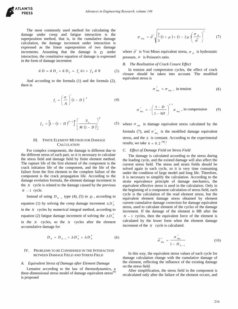
Life prediction of the specimen of FGH95 nickel based powder alloy plate under creep and fatigue interaction is taken as an example. The shape and size of the specimen are
shown in Figure 2. The thickness of the specimen is mm2 .
The stress ratio 1R , and the test temperature
0580T . When the creep damage is calculated, the
material parameter[9] of FGH95 is: MPa1210Z ,
17.17r , MPa1923A , 1589190
.a , 3
11042991
.a , 4
2108911
.a . When the
fatigue damage is calculated, the material parameter[9] of
FGH95 is: 55.16 , 9650 .a , 001160 .b ,
MPa.96800M .
6
34
12
R2.5
R0.
5
2 4 18
Figure 2. Schematic diagram of plate specimen.
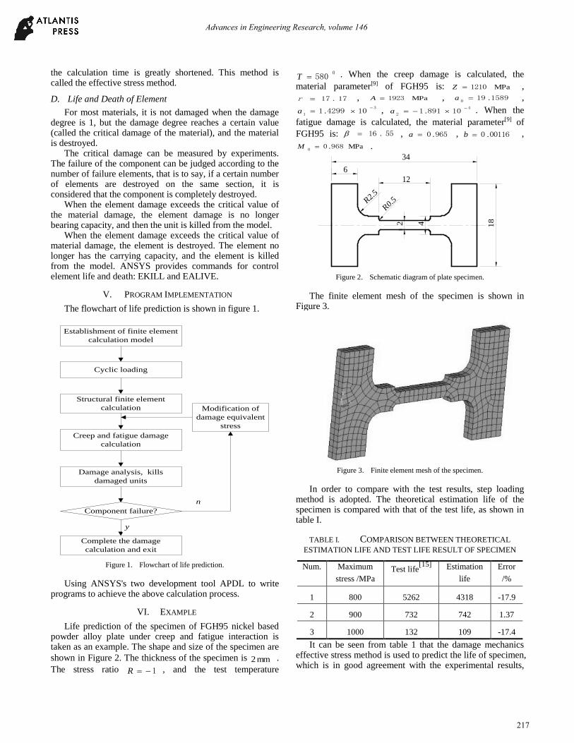
The finite element mesh of the specimen is shown in Figure 3.
Figure 3. Finite element mesh of the specimen.
In order to compare with the test results, step loading method is adopted. The theoretical estimation life of the specimen is compared with that of the test life, as shown in table I.
TABLE I. COMPARISON BETWEEN THEORETICAL
ESTIMATION LIFE AND TEST LIFE RESULT OF SPECIMEN
Num. Maximum
stress /MPa Test life
[15] Estimation
life
Error
/%
1 800 5262 4318 -17.9
2 900 732 742 1.37
3 1000 132 109 -17.4
It can be seen from table 1 that the damage mechanics effective stress method is used to predict the life of specimen, which is in good agreement with the experimental results,
Advances in Engineering Research, volume 146
217
which shows that this method is feasible in predicting the component.
The creep damage life of the component is calculated, and the results are compared with those calculated by creep and fatigue interaction damage. As shown in table II.
TABLE II. COMPARISON OF CREEP DAMAGE LIFE AND
CREEP AND FATIGUE INTERACTION DAMAGE LIFE
Num. Maximum
stress /MPa
Creep life interaction
damage life
Error
/%
1 800 4372 4318 1.2
2 900 754 742 1.6
3 1000 112 109 2.7
It can be seen from the table 2 that the creep life is almost the same as the interaction life, and therefore the creep damage is dominant.
In the case of only considering the fatigue damage at the maximum stress (1000Mpa), the life is more than 10000 times, far higher than the interaction life. This shows that the fatigue damage plays a minor role in the life prediction simulation.
VII. CONCLUSIONS
(1) The damage mechanics-effective stress method for predicting the fatigue life of structures under the interaction of creep and fatigue is given. The effective stress method is used to calculate the stress field of the component, and the calculation efficiency is improved. The damage prediction and life prediction of components are realized by combining the life prediction method based on damage mechanics with the structural analysis of ANSYS by using APDL.
(2) The damage mechanics-effective stress method is used to predict the life of FGH95 material plate structure, and the results are in good agreement with the test results.
(3) In this case, the creep damage dominates the total damage, and fatigue damage is secondary.
REFERENCES
[1] Chen G L, “Fatigue-creep interaction fracture maps and life prediction under combined fatigue-creep stress cycling,” Journal of Materials Science & Technology, vol. 6, 1990, pp. 391-414.
[2] Hongyin Mao, Sankaran and Mahadevan, “Reliability analysis of creep-fatigue,” Failure International Journal of Fatigue, vol. 22, 2000, pp. 789-797.
[3] Pu Ze-lin, Yang Kun and Liu Zong-de, “An experimental study on fatigue behavior-and life prediction model of coupling bolt for the steam turbine,” Proceedings of the CSEE, vol. 22, 2002, pp. 90-94.
[4] Fan Zhi-chao and Chen Xue-dong, “JIANG Jia-ling. Cyclic creep and fatigue interaction cdm model of 16MnR steel,” Acta Mechaniea Solida Sinica, vol. 27, 2006, pp. 65-70.
[5] Jing Jian-ping and Meng Guang, “On the fatigue-creep damage analysis of a steam turbine rotor by a nonlinear contim uum damage mechanics model,” Proceedings of the CSEE, vol. 23, 2003, pp. 167-172.
[6] Jing Jianping and Sun Yi, “A continuum damage mechanics model on low cycle fatigue life. Assessment of stram turbine rotor,” International Journal of Pressure Vessels and Piping, vol. 78, 2001, pp. 59-64.
[7] Shi Duo-qi, Yang Xiao-guang and Wang Yan-rong, “Applied Investigation of Chaboche’s Unified Visco-Plastic Consititutive Model of Coupled Creep Damage,” Journal of Aerospace Power, vol. 20, 2005, pp. 61-63.
[8] Wang Jun, The Theory and Application of Damage Mechanics. Beijing: Science Press, 1997.
[9] Liu Xiang-xin, Zhang Xue-ren,Yan Xiao-jun and Nie Jing-xu, “The Element Analysis of HLCF Life Prediction for PM FGH95 Based on Damage Mechanics,” Journal of Aerospace Power, vol. 18, 2003, pp. 102-106.
Advances in Engineering Research, volume 146
218