Prediction of aerodynamic characteristics of a box girder ...
17
Journal of Wind Engineering and Industrial Aerodynamics 96 (2008) 1895–1911 Prediction of aerodynamic characteristics of a box girder bridge section using the LES turbulence model M.W. Sarwar a, , T. Ishihara a , K. Shimada b , Y. Yamasaki c , T. Ikeda d a Institute of Engineering Innovation, School of Engineering, The University of Tokyo, 2-11-16, Yayoi, Bunkyo-ku, Tokyo 113-8656, Japan b Institute of Technology, Shimizu Corporation, 3-4-17, Etchujima, Koto-ku, Tokyo, Japan c Bridge and Road Construction Division, Ishikawajima-Harima Heavy Industry Co. Ltd., 2-2-1 Otemachi, Chiyoda-ku, Tokyo, Japan d International Division, Chodai Co. Ltd., 20-4, 1-Chome, Nihonbashi-kakigaracho, Chuo-ku, Tokyo, Japan Available online 18 April 2008 Abstract In this study, aerodynamic characteristics of a box girder bridge section are investigated by three- dimensional computational fluid dynamics using the LES turbulence model. Flow around the streamline box girder section is analyzed, and the effect of section details on the aerodynamic characteristics of bridge section is evaluated. In addition, forced vibration cases are simulated to investigate the aeroelastic behavior of rectangular sections with a high aspect ratio. The flutter characteristics of a box girder bridge section (B/D ¼ 11.6) are investigated and compared with experimental results of the generic rectangular cross-sections. Finally, influence of the geometrical modifications on the aeroelastic instability of the bridge section is pursued. r 2008 Elsevier Ltd. All rights reserved. Keywords: LES; Aerodynamic coefficients; Flutter analysis; Box girder bridge section; Section attachments; Computational fluid dynamics 1. Introduction The safe design of large civil engineering structures like cable-stayed bridges requires investigations on the dynamic response under unsteady wind loads. In this respect, ARTICLE IN PRESS www.elsevier.com/locate/jweia 0167-6105/$ - see front matter r 2008 Elsevier Ltd. All rights reserved. doi:10.1016/j.jweia.2008.02.015 Corresponding author. Tel.: +81 35 841 1145; fax: +81 35 841 1147. E-mail address: [email protected] (M.W. Sarwar).
Transcript of Prediction of aerodynamic characteristics of a box girder ...

ARTICLE IN PRESS
Journal of Wind Engineering
and Industrial Aerodynamics 96 (2008) 1895–1911
0167-6105/$ -
doi:10.1016/j
�CorrespoE-mail ad
www.elsevier.com/locate/jweia
Prediction of aerodynamic characteristics of a boxgirder bridge section using the LES turbulence model
M.W. Sarwara,�, T. Ishiharaa, K. Shimadab, Y. Yamasakic, T. Ikedad
aInstitute of Engineering Innovation, School of Engineering, The University of Tokyo, 2-11-16,
Yayoi, Bunkyo-ku, Tokyo 113-8656, JapanbInstitute of Technology, Shimizu Corporation, 3-4-17, Etchujima, Koto-ku, Tokyo, Japan
cBridge and Road Construction Division, Ishikawajima-Harima Heavy Industry Co. Ltd., 2-2-1 Otemachi,
Chiyoda-ku, Tokyo, JapandInternational Division, Chodai Co. Ltd., 20-4, 1-Chome, Nihonbashi-kakigaracho, Chuo-ku, Tokyo, Japan
Available online 18 April 2008
Abstract
In this study, aerodynamic characteristics of a box girder bridge section are investigated by three-
dimensional computational fluid dynamics using the LES turbulence model. Flow around the
streamline box girder section is analyzed, and the effect of section details on the aerodynamic
characteristics of bridge section is evaluated. In addition, forced vibration cases are simulated to
investigate the aeroelastic behavior of rectangular sections with a high aspect ratio. The flutter
characteristics of a box girder bridge section (B/D ¼ 11.6) are investigated and compared with
experimental results of the generic rectangular cross-sections. Finally, influence of the geometrical
modifications on the aeroelastic instability of the bridge section is pursued.
r 2008 Elsevier Ltd. All rights reserved.
Keywords: LES; Aerodynamic coefficients; Flutter analysis; Box girder bridge section; Section attachments;
Computational fluid dynamics
1. Introduction
The safe design of large civil engineering structures like cable-stayed bridges requiresinvestigations on the dynamic response under unsteady wind loads. In this respect,
see front matter r 2008 Elsevier Ltd. All rights reserved.
.jweia.2008.02.015
nding author. Tel.: +8135 841 1145; fax: +81 35 841 1147.
dress: [email protected] (M.W. Sarwar).

ARTICLE IN PRESSM.W. Sarwar et al. / J. Wind Eng. Ind. Aerodyn. 96 (2008) 1895–19111896
aeroelastic instabilities of rectangular prisms, because of their common use in bridgeindustry, have received particular interest from both academic and practical standpoints.Rectangular prisms have quite unique aerodynamic characteristics in the present context;boundary layers separating from the sharp edges may remain separated or haveintermittent attachment to the surface of the prism depending on the aspect ratio.Matsumoto (1996) and Matsumoto et al. (1994, 1996) have conducted detailedexperimental investigations to understand the aeroelastic characteristics of a rectangularsection with a high aspect ratio. This study introduced step-by-step analysis that has shownthe predominance of A1
*, A2* and H3
* on flutter characteristics. Recently, the k-e model wasemployed for the flutter analysis of rectangular sections of varying width to depth ratio byShimada et al. (2002). However, this study resulted in conservative prediction of the criticalflutter velocity for elongated sections, i.e., B/D ¼ 10 and 20.The above mentioned analysis examples are examinations concerning flat rectangular
sections assuming that there are no section attachments, e.g., handrails, etc. However, it isgeneral in the field of bridge engineering that many modifications are done to the basicrectangular shapes for obtaining aerodynamically stable cross-sections, e.g., introductionof fairings or for operational purposes like handrails, central barrier, etc. Recently,many studies have shown the use of CFD for predicting the steady and unsteadyaerodynamic characteristics of bridge sections. For example, Larsen and Walther (1998)have reported the applicability the of two-dimensional discrete vortex method to predictthe flutter characteristics of some generic configuration at first and then extended it tosome practical bridge cross-sections. However, this study has resulted in conservativeprediction of the flutter critical velocity. Further, Larsen (2006) has reported computationof the aerodynamic derivatives of the box girder section by various 3D CFD techniques.The predicted critical velocity was reported to be sufficiently accurate for LES andDES; however, use of the k-o model resulted in underestimation of the critical fluttervelocity by 18%.Though the actual bridge sections include small attachments like handrails, central
barrier, etc. previous works have neglected the presence of such details. Therefore, lack ofmodeling such small details limits the extent of reliability of numerical works that are ofmuch interest from the engineering point of view. Such section details, no matter howsmall in size compared with the size of the bridge section, can dramatically affect theaerodynamic characteristics of the bridge section not only by controlling the separationpoint of shear layers but also by changing the flow characteristics around the bridgesection (Jones et al., 1995). In addition, Bruno et al. (1998) investigated the effect of sectiondetails on the aerodynamic instability of bridge deck using the k-e model. Investigationswere carried out to investigate the effect of each detail in the absence of others, as well ason the overall behavior in the presence of all details. Even minor changes made to thecross-sectional geometry by safety barriers or sidewalks have shown strong influence onthe flow pattern not only in the vicinity of these attachments but also on the sectioncharacteristics as a whole. Therefore, it seems necessary at this point to clarify the influenceof such details on the overall aerodynamic behavior of the bridge sections.Recently, Ishihara et al. (2006a) have reported the successful prediction of the flow field
around the square prism circumference by LES. Not only the mean pressure coefficient(Cp) but also the fluctuating component of pressure coefficient (Cp) were reproduced thatagreed well with the experimental measurements. The simulation accuracy was furtherexamined by performing an unsteady analysis for a real bridge section under construction,

ARTICLE IN PRESSM.W. Sarwar et al. / J. Wind Eng. Ind. Aerodyn. 96 (2008) 1895–1911 1897
and has shown the influence of section attachments such as handrails, etc. on the steadyaerodynamic coefficients (Ishihara et al., 2006b).
In this paper, the analysis accuracy of the LES model for the real bridge cross-sectionwith section details is investigated. The steady aerodynamic characteristics of the boxgirder section are obtained by employing the LES model and the effect of small sectiondetails, e.g., hand rails, inspection rails, etc., on these characteristics are examined, andcomparison with wind tunnel experiments is presented. In addition, forced vibrationanalysis is conducted following Matsumoto et al. (1994) to investigate the fluttercharacteristics of the box girder bridge section, and the aerodynamic instability of the boxgirder bridge section with reference to the rectangular sections of similar width to depthratio is presented. Further, influence of the geometrical modifications on the aeroelasticinstability of the bridge section is summarized. Based on numerical results, application ofthe LES model to the prediction of flutter critical velocity is discussed.
2. Numerical approach
The LES turbulence model is used in this study in which small eddies are modeled whereas large eddies are directly calculated. The finite volume method was used for thediscretization of governing equations. Central difference scheme for convective terms andthe second-order implicit scheme for unsteady terms were used. The SIMPLEC methodwas used to solve the discretized equations. The oscillation of the simulation models isachieved by employing the sliding mesh technique. FLUENT (2005) CFD software is usedas solver.
2.1. Governing equations
The governing equations employed for LES are obtained by filtering the time-dependentNavier–Stokes equations as follows:
qrui
qxi
¼ 0;qqtðruiÞ þ
qqxj
ðruiujÞ ¼qqxj
mqui
qxj
� ��
qp
qxi
�qtij
qxj
(1)
where %uj and p are filtered mean velocity and filtered pressure, respectively. tij is the subgrid-scale stress resulting from the filtering operation that is unknown and is modeled as
tij ¼ �2mtSij þ1
3tkkdij ; Sij ¼
1
2
qui
qxj
þquj
qxi
� �(2)
where mt is the subgrid-scale turbulent viscosity, and Sij is the rate-of-strain tensor.
2.2. Smagorinsky-lilly model
The subgrid-scale turbulent viscosity (mt) is modeled using the Smagorinsky model,where the eddy viscosity is modeled as
mt ¼ rL2s jSj ¼ rLs
ffiffiffiffiffiffiffiffiffiffiffiffiffi2Sij Sij
q; Ls ¼ minðkd;CsV
1=3Þ (3)

ARTICLE IN PRESSM.W. Sarwar et al. / J. Wind Eng. Ind. Aerodyn. 96 (2008) 1895–19111898
where Ls is the mixing length for subgrid scales, k is the von Karman constant, Cs is theSmagorinsky constant, d is the distance to the closest wall, and V is the volume of thecomputational cell.
2.3. Description of grid domain
The geometries used in this study are elongated rectangular sections (i.e., width to depthratio of 10 and 20), and a box girder bridge section with and without section details. Thecomputational domain used for both steady and unsteady analyses is shown in Fig. 1,where the domain is divided into static and moving zones.The width and depth of the domains are 105D and 60D, respectively. A close-up of the
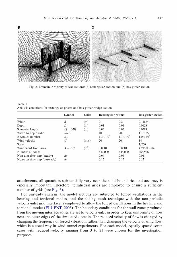
mesh generated around the test sections is shown in Fig. 2. The corners of rectangularsections are considered rounded with a radius to depth ratio (r/D) of 0.01 and small sizemeshes are generated near each edge corner to avoid singularity of the solutions, andequally distributed 12 meshes were used in the span wise direction. The dimensions ofmodel sections and analysis conditions used in this study are summarized in Table 1.Inflow wind velocity ‘‘U’’ is kept constant for any case to avoid any additionalphenomenon, if any, arising with the change in Reynolds number (RN). Also, throughoutunsteady investigations, the angle of attack, i.e. the angle between the direction of width B
and that of the uniform flow, was kept zero. The maximum intensity of turbulence is of theorder of 0.001% at the inlet boundary. Symmetry condition was used for the top andbottom surfaces of the domain.The steady aerodynamic coefficients of the streamline box girder bridge section are
investigated for both cases, with and without section attachments like handrails, inspectionrails, central barrier, etc. To include these attachments, a schematic use of structured/unstructured grid is introduced around the complex geometry (see Fig. 2b). First, thedomain of interest is divided into two parts where regions away from the section aremodeled using a structured grid, and the domain near and around the complex geometry isfurther divided into sub-domains. Within these sub-domains, which contain small
Rotational Zone
15D 30D 60D
Inlet
Outlet
Static Zone Heaving Zone
Interface
Fig. 1. Computational domain for steady and unsteady cases.
ARTICLE IN PRESS
Fig. 2. Domain in vicinity of test sections: (a) rectangular section and (b) box girder section.
Table 1
Analysis conditions for rectangular prisms and box girder bridge section
Symbol Units Rectangular prisms Box girder section
Width B (m) 0.1 0.2 0.14864
Depth D (m) 0.01 0.01 0.0128
Spanwise length L( ¼ 3D) (m) 0.03 0.03 0.0384
Width to depth ratio B/D 10 20 11.6125
Reynolds number RN 1.3� 104 1.3� 104 1.0� 104
Wind velocity U (m/s) 20 20 14
Scale 1/250
Wind word front area A ¼ LD (m2) 0.0001 0.0001 4.9152E�04
Number of nodes 439,000 448,000 466,908
Non-dim time step (steady) Dt 0.04 0.04 0.04
Non-dim time step (unsteady) Dt 0.15 0.15 0.12
M.W. Sarwar et al. / J. Wind Eng. Ind. Aerodyn. 96 (2008) 1895–1911 1899
attachments, all quantities substantially vary near the solid boundaries and accuracy isespecially important. Therefore, tetrahedral grids are employed to ensure a sufficientnumber of grids (see Fig. 3).
For unsteady analysis, the model sections are subjected to forced oscillations in theheaving and torsional modes, and the sliding mesh technique with the non-periodicvelocity-inlet grid interface is employed to allow the forced oscillations in the heaving andtorsional modes (FLUENT, 2005). The boundary conditions for the wall zones producedfrom the moving interface zones are set to velocity-inlet in order to keep uniformity of flownear the outer edges of the simulated domain. The reduced velocity of flow is changed bychanging the frequency of forced vibration, rather than changing the velocity of wind flow,which is a usual way in wind tunnel experiments. For each model, equally spaced sevencases with reduced velocity ranging from 3 to 21 were chosen for the investigationpurposes.

ARTICLE IN PRESS
Fig. 3. Details of mesh generation around the section attachments: (a) Upwind handrails; (b) Central barrier and
(c) inspection rails.
M.W. Sarwar et al. / J. Wind Eng. Ind. Aerodyn. 96 (2008) 1895–19111900
3. Modeling details and aerodynamic coefficients
This section includes the discussion based on steady investigations to determine theinfluence of geometrical modifications and section details on the aerodynamiccharacteristics. Further, modification in flow field around the streamline section due tothe section attachments is examined.
3.1. Reynolds dependency of aerodynamic coefficients
Definition of the forces acting on model sections and the angle of attack along withdisplacement are shown in Fig. 4. Definition of mean aerodynamic force coefficients issummarized below:
CD ¼FD
1=2rU2DL(4)

ARTICLE IN PRESS
Fig. 4. Positive definitions of global forces and angle of attack.
M.W. Sarwar et al. / J. Wind Eng. Ind. Aerodyn. 96 (2008) 1895–1911 1901
CL ¼FL
1=2rU2BL(5)
CM ¼F M
1=2rU2B2L. (6)
An experimental Reynolds number (RN) dependency study for the box girder sectionwas conducted for both cases, with and without section attachments. The height of themodel is chosen so that the blockage ratio remains below 3%. The details of theexperiment performed to determine the steady aerodynamic coefficients are summarized inRef. Ishihara et al. (2006b). The steady aerodynamic coefficients of sections with andwithout small attachments remain undisturbed with increase in Reynolds number. Sincemeasurements at low wind velocity may strongly influence the accuracy of the results,Reynolds number was kept constant (RN ¼ 3.5� 104) throughout the experiments for bothsections (i.e., with and without handrails and inspection rails). However, the numericalsimulations are performed at a relatively low Reynolds number, i.e., RN ¼ 1.0� 104.
3.2. Coefficients of mean aerodynamic forces
Fig. 5 shows the dependence of mean aerodynamic coefficients on the angles of attack,ranging from �151 to +151, for the streamline box girder section with and without smallattachments, using LES and k–e models.
In Fig. 5a, CD attains the minimum value at about 01 and a moderate increase in CD isobserved in the range of +71 to �71. Rather rapid increase in CD is observed with furtherincrease in the angle of attack for both cases. At a smaller angle of attack, the dragcoefficient of the bridge section without attachments turns out to be one-third of thesection with small attachments and also smaller than the rectangular sections, e.g., forB/D ¼ 20–10, CD ranges from 0.8 to 1.0, respectively. The use of the 2D standard k–emodel overestimates the drag acting on the bridge section for both cases, whereas LESresults show good agreement with those of the experimental ones. The contribution of eachcomponent of the bridge section is summarized in Fig. 6a. At 01, the cumulative dragacting on handrails and inspection rails turns out to be larger than that acting on thebridge section only. At larger angles, most of the drag is contributed from the bridgesection compared to the small attachments. For a positive large angle of attacks, the drag

ARTICLE IN PRESS
0
1
2
3
4
5Cd - with handrails etc (exp)Cd - with handrails etc (LES)
Cd - w/o handrails etc (exp)Cd - w/o handrails etc (LES)
Cd - with handrails etc (κ−ε)
Cd - w/o handrails etc (κ−ε)
Angle (α)
CD
-1.5
-1
-0.5
0
0.5
1
1.5
CL
Angle (α)
-0.3
-0.2
-0.1
0
0.1
0.2
0.3
-15
CM
Angle (α)151050-5-10
-15 151050-5-10
-15 151050-5-10
Fig. 5. Comparison of experimental and numerical aerodynamic coefficients of a box girder bridge section with
and without handrails: (a) drag coefficient, (b) lift coefficient and (c) moment coefficient.
M.W. Sarwar et al. / J. Wind Eng. Ind. Aerodyn. 96 (2008) 1895–19111902

ARTICLE IN PRESS
0
0.5
1
1.5
2
2.5
3
3.5
4
-12 -9 -6 -3 0 3 6 9 12
-12 -9 -6 -3 0 3 6 9 12
-12 -9 -6 -3 0 3 6 9 12
Angle of attack
CD
Inspection rails Handrails Bridge section
-1.2
-1
-0.8
-0.6
-0.4
-0.2
0
0.2
0.4
0.6
0.8
Angle of Attack
CL
-0.25
-0.2
-0.15
-0.1
-0.05
0
0.05
0.1
0.15
0.2
Angle of attack
CM
Inspection rails Handrails Bridge section
Inspection rails Handrails Bridge section
Fig. 6. Contribution of handrails and inspection rails to the aerodynamic coefficients of the bridge section by
LES: (a) drag coefficient, (b) lift coefficient and (c) moment coefficient.
M.W. Sarwar et al. / J. Wind Eng. Ind. Aerodyn. 96 (2008) 1895–1911 1903
force acting on handrails reduces to zero at 121 and that on the inspection rails is doubled.However, for a negative angle of attacks, contribution of the drag from inspection rails isdiminished and that from the handrails is increased.
The small section attachments do not significantly influence the lift force coefficient fornegative attack angles, but the peak observed at the positive attack angle for the section

ARTICLE IN PRESSM.W. Sarwar et al. / J. Wind Eng. Ind. Aerodyn. 96 (2008) 1895–19111904
without attachments disappears in the presence of these attachments, whose mechanismwill be explained in the next section. Also, the magnitude of lift force acting on hand andinspection rails becomes negligible, see Fig. 6b, and reduction in the lift force is mainly dueto modification of the flow field around the bridge section by these attachments. In theabsence of section attachments, the moment coefficient (CM) increases naturally with anincrease in attack angle and a maximum value occurs at about +121 and �91. However,presence of small attachments has contained the moment at positive attack angles. Fig. 6cshows that, for a positive range of attack angles, the contribution of handrails to momentcoefficients remains positive and inspection rails have shown negative contribution.Thus, inclusion of the small attachments may cause favorable or adverse influence onthe aerodynamic characteristics of the bridge section, which will be discussed in thenext section.In short, the use of fairing to modify the rectangular sections reduces the drag force
acting on the bridge section. However, the inclusion of small section attachments results ina higher drag force that depends on the size and density of these attachments. Thus, itshows the very importance of the modeling section details in order to obtain realisticaerodynamic behavior of the bridge sections.
3.3. Mean flow around the box girder bridge section
Looking at the flow field (Fig. 7) around the box girder section would help to identifythe characteristics of mean force coefficients. Flow characteristics at three attack angles arediscussed where large differences between aerodynamic coefficients of both bridge sectionsexist.
Fig. 7. Mean streamlines at different angle of attacks for the box girder bridge section without (left) and with
(right) handrails. (a) a ¼ 01, (b) a ¼ 91 and (c) a ¼ 121.

ARTICLE IN PRESSM.W. Sarwar et al. / J. Wind Eng. Ind. Aerodyn. 96 (2008) 1895–1911 1905
At an attack angle of 01, in case of section without attachments, the large positivepressure acting on fairing is followed by flow separation over a very small region on thewindward side of the upper surface, as shown in Fig. 7a. The separated flow thenreattaches to the upper surface and pressure recovery occurs. On the lower surface,separation of flow shows large negative pressure at the end of the lower flap, and thefollowing reattachment of flow towards the leeward side indicates recovery of pressure onthe lower surface of section (Fig. 7a).
In case of bridge section with attachments, at zero angle of attack, the flow is interceptedby the presence of handrails in addition to that acting on the upper flap surface. However,the flow along the upper surface remains separated and reattaches to the upper surface inthe vicinity of leeward edge. On the other hand, the flow separation is intensified by thepresence of a first handrail on the upper surface. The flow pattern around the section withattachments, as seen in Fig. 7a, shows that the flow separation on the lower surface causedby the first inspection rail reattaches between the 2nd and 3rd inspection rails. But nextinspection rails again cause flow detachment. Thus, it shows the contribution of sectiondetails to the drag coefficient at 01, as observed in Fig. 6a, which corresponds to the largedrag force acting on the hand and inspection rails.
Fig. 7b shows the flow pattern around both sections at an attack angle of 91. For thesection without attachments, separation of flow on the upper surface intensifies and thelength of separated flow increases with increase in the angle of attack, and flow reattachesto the upper surface near the mid of section width (Fig. 7b). On the lower surface, shearlayers formed near the corners disappear by the time the angle changes to 91. The negativepressure at the upper surface and positive pressure at the lower surface maximizes at thisangle, and a large lift force is experienced by the bridge section as shown in the previoussection. However, in case of section with attachments, flow separation intensifies on thewindward side with an increase in the angle of attack and shows intermittent reattachmentto the upper surface. At this angle, the windward handrails are still subjected to flowseparating from the upper flange of fairing, and are contributing to the drag force. Also,increase in distance from the center of the bridge section results in large contribution tomoment coefficient by the handrails. However, on the lower surface, flow reattaches in anintermittent fashion due to vortex formation behind the inspection rails. The negativepressure caused by separated flow thus results in a rather lower lift acting on the bridgesection.
Fig. 7c shows the flow around both sections for a negative attack angle of 121. On theupper surface of both sections, flow remains attached to the surface but all the handrailsare exposed to a rather mild flow. Whereas on the lower surface, intensive negativepressure at the leading edge is improved by pressure recovery towards the leeward side inboth cases, see Fig. 7c. The inspection rails come in wake of leading edge and do notinfluence the flow field that is observed in case of positive attack angles, see Fig. 7a, b. Thedifference in flow field around both sections remains quite minimal that results into almostsimilar force coefficients, which are found consistent with those of experimental values, asshown in Fig. 5.
4. Estimation of aerodynamic derivatives
In this study, the unsteady aerodynamic forces are simulated using the forced verticaland rotational excitations of a single degree of freedom system that are later used for

ARTICLE IN PRESSM.W. Sarwar et al. / J. Wind Eng. Ind. Aerodyn. 96 (2008) 1895–19111906
evaluating the aerodynamic derivatives. The force time histories obtained by forcedvertical and rotational excitations are decomposed into components corresponding to theaerodynamic damping and stiffness by using Fourier decomposition (Washizu et al., 1978).Following the experiments by Matsumoto et al. (1994), in this study, the amplitudes ofvibrations in heaving and torsional motions are kept as y0/B ¼ 0.025 and a0 ¼ 21. Throughmeasurement of the pressure distribution along periphery of sections, eight aerodynamicderivatives proposed by Scanlan and Tomko (1971) were obtained where unsteady lift (L)and pitching moment (M) are expressed as follows:
L ¼1
2rU2ð2bÞ kH�1
h
Uþ kH�2
baUþ k2H�3aþ k2H�4
h
b
� �(7)
M ¼1
2rU2ð2b2
Þ kA�1h
Uþ kA�2
baUþ k2A�3aþ k2A�4
h
b
� �(8)
where k ¼ bo/U, B ¼ 2b is the girder width, U is the mean wind velocity and o is thebridge oscillating frequency in rad/s.Experimental investigations of the same box girder section without section attachments
were conducted by Zhu et al. (2006) to determine the influence of yaw angle on fluttercharacteristics. The dominant aerodynamic flutter derivatives of the box girder sectionwithout section attachments are shown in Fig. 8. The experimental flutter derivatives of thebox girder section (Zhu et al., 2006) shows the tendency of A2
* similar to that of therectangular section B/D ¼ 20. The simulated derivatives of the box girder section haveshown good agreement with the experimental results, thus validating the accuracy of theLES model to examine the flutter characteristics of the box girder section.Fig. 9 shows the simulated aerodynamic derivatives of rectangular sections with a width
to depth ratio of 10 and 20 in comparison to those of the experimental results. Theaerodynamic coefficients of the coupled derivative terms are found to be in goodagreement with the experimental ones. However, predicted uncoupled terms for both
-40
-20
0
20
40
0
B/D = 10 B/D = 20 Box Girder Section (Exp.) Box Girder Section (LES)
U/(fB)
A2*
-400
-300
-200
-100
0
100
B/D = 10 B/D = 20 Box Girder Section ( Exp.) Box Girder Section (LES)
U/(fB)
H3*
252015105 0 252015105
Fig. 8. Comparison of the simulated (LES) and experimental (Zhu et al., 2006) flutter derivatives for the box
girder section, without handrails and inspection rails, along with rectangular sections (Matsumoto et al., 1994).

ARTICLE IN PRESS
0
20
40
60
80
100
0
B/D=10 (Exp.)B/D=12.5 (Exp.)B/D=20 (Exp.)B/D=10 (LES)B/D=20 (LES)section w/o attach. (LES)section with attach. (LES)
A1*
A2*
A4*A3
*
H1* H2
*
U/(fB)
-50
0
50
100
150
U/(fB)
-50
0
50
100
150
200
250
U/(fB)
-50
-25
0
25
50
U/(fB)
-100
-50
0
50
U/(fB)
-50
0
50
100
150
200
U/(fB)
-400
-300
-200
-100
0
100
200
U/(fB)
-20
-15
-10
-5
0
5
10
15
20
U/(fB)
252015105
0 252015105
0 252015105
0 252015105
0 2520151050 252015105
0 252015105 0 252015105
Fig. 9. Comparison of experimental (Matsumoto et al., 1994) and simulated flutter derivatives of rectangular
sections, and those of box girder bridge sections, with and without small attachments.
M.W. Sarwar et al. / J. Wind Eng. Ind. Aerodyn. 96 (2008) 1895–1911 1907

ARTICLE IN PRESSM.W. Sarwar et al. / J. Wind Eng. Ind. Aerodyn. 96 (2008) 1895–19111908
sections turn out to be similar. This is due to small amplitudes of vibrations used inheaving and torsional modes to evaluate the unsteady aerodynamic derivatives. It couldalso be seen from the steady aerodynamic coefficients at small attack angles, which aresimilar for both rectangular sections. Since uncoupled terms are known to have lesscontribution to the flutter characteristics, flutter characteristics of the box girder bridgesection are pursued.The simulated flutter derivatives of the bridge section with small attachments
(B/D ¼ 11.6) show a close resemblance to those of the rectangular section with a higherwidth to depth ratio, i.e. 20, than the rectangular section of similar aspect ratio of 10, asshown in Fig. 9. This shows the dominant influence of the fairings used to obtain a bridgegirder section that has limited separation of the shear layer and rather earlier reattachmentof flow occurs. A good agreement is found among the aerodynamic derivatives of thebridge section and those of the elongated rectangular section with B/D ¼ 20. To clarify theeffect of hand and inspection rails, unsteady aerodynamic force coefficients of the bridgesection without handrails are included at few reduced velocities and simulated flutterderivatives are summarized in Fig. 9. The moment derivative terms are found undisturbedby the introduction of small section attachments. However, the flutter derivativescorresponding to heaving of sections show rather large differences as shown in Fig. 9. Thisbehavior of sections can be attributed to the difference observed for the static liftcoefficients at the low angle of attacks, refer to Fig. 5b.
5. Flutter characteristics
Complex eigen value analysis, proposed by Miyata and Yamada (1990), is used todetermine the circular frequency and logarithmic damping for heaving and torsionalbranches using the flutter derivatives obtained in the last section. Figs. 10 and 11 show theflutter frequency and the flutter damping ratio of rectangular sections with aspect ratios of10 and 20, respectively. In Fig. 10a, it is obvious that the frequencies of two branches neckdown near the reduced velocity corresponding to the critical flutter velocity, and again
0
2
4
6
8
10
0
B/D=10 (Exp)B/D=10 (LES)
Freq
uenc
y
U/fB
Torsional Branch
Heaving Branch
-0.75
-0.5
-0.25
0
0.25
0.5
0.75
1B/D=10 (Exp.)B/D=10 (κ-ε)B/D=10 (LES)
Logr
athi
mic
Dam
ping
(δ)
U/fB
Heaving Branch
Torsional Branch
21181512963 0 21181512963
Fig. 10. Eigen value loci of rectangular section with B/D ¼ 10 (experiment, k-e), M ¼ 1.96 kg/m,
I ¼ 4.9� 10�3Kgm, fZ0 ¼ 4.5Hz, fo0 ¼ 6.0Hz, B( ¼ 2b) ¼ 0.15m.

ARTICLE IN PRESS
0
2
4
6
8
10
0
B/D = 20 ( Exp.)B/D = 20 (LES )
Freq
uenc
y
U/fB
Torsional Branch
Heaving Branch
-0.75
-0.5
-0.25
0
0.25
0.5
0.75
1B/D=20 (Exp.)B/D=20 (κ-ε)B/D=20 (LES)
Logr
athi
mic
Dam
ping
(δ)
U/fB
Heaving Branch
Torsional Branch
21181512963 0 21181512963
Fig. 11. Eigen value loci of rectangular sections with B/D ¼ 20 (experiment, k-e) M ¼ 1.96 kg/m,
I ¼ 4.9� 10�3Kgm, fZ0 ¼ 4.5Hz, fo0 ¼ 6.0Hz, B( ¼ 2b) ¼ 0.15m.
M.W. Sarwar et al. / J. Wind Eng. Ind. Aerodyn. 96 (2008) 1895–1911 1909
tends to part from each other at higher velocities. In case of flutter damping ratio, LESsimulation shows increase in positive heaving branch and the damping ratio correspondingto the torsional mode changes from positive to negative at a reduced velocity of 9(Fig. 10b). This indicates the possibility of torsional-type flutter at a reduced velocity,which is close to the critical flutter velocity of the section with B/D ¼ 10 as reported byprevious experimental study (Matsumoto et al., 1994). The logarithmic damping of bothheaving and torsional branches is found to be in good agreement with experimental results(see Fig. 10b).
In case of rectangular section with an aspect ratio of 20, see Fig. 11a, flutter frequenciesof two branches neck down near the reduced velocity of 13, which corresponds to thecritical flutter velocity, and again tends to part from each other at higher reducedvelocities. In case of flutter damping ratio, LES simulation shows an increase in positiveheaving branch and the damping ratio corresponding to torsional mode changes frompositive to negative at a reduced velocity of 13 (Fig. 11b). This indicates the possibility oftorsional-type flutter at the intersection-reduced velocity, which is close to the criticalflutter velocity identified by previous experimental study (Matsumoto et al., 1994).
It is noteworthy to mention here the work reported by Shimada et al. (2002), where thek–e model has shown conservative results for rectangular sections of similar aspect ratio,Figs. 10 and 11. This discrepancy in the identified flutter critical velocity was found due tothe inaccurate prediction of aerodynamic coefficients A1
* and H3*. On the other hand, LES
has shown better prediction of such aerodynamic derivatives. Thus, it shows theeffectiveness of 3D LES over a 2D k–e model to predict the flutter characteristics.
In case of streamline bridge section with an aspect ratio of 11.6, calculated heaving andtorsional frequencies lead to torsional-branch coupled flutter type that coincides with theflutter characteristics of a rectangular prism with an aspect ratio of 20 (Fig. 12a). Thelogarithmic damping of the heaving branch remains positive for box girder sections withsmall attachments (Fig. 12b). However, logarithmic damping of the torsional branchbecomes negative at high reduced velocity of 13 which is similar to that of the rectangularsection with B/D ¼ 20. The box girder section (B/D ¼ 11.6) has shown higher critical

ARTICLE IN PRESS
-0.75
-0.5
-0.25
0
0.25
0.5
0.75
1B/D = 20 (Exp.)Section with handrailsSection without handrails
Heaving Branch
Torsional Branch
Dam
ping
ratio
U/fB0 21181512963
0
2
4
6
8
10
0 3 6 9 12 15 18 21
B/D = 20 (Exp.)Section with handrailsSection without handrails
Freq
uenc
y
U/fB
Torsional Branch
Heaving Branch
Fig. 12. Comparison of eigen value loci of the box girder bridge section with and without attachments along with
the rectangular section (B/D ¼ 20). M ¼ 1.96 kg/m, I ¼ 4.9� 10�3Kgm, fZ0 ¼ 4.5Hz, fo0 ¼ 6.0Hz,
B( ¼ 2b) ¼ 0.15m.
M.W. Sarwar et al. / J. Wind Eng. Ind. Aerodyn. 96 (2008) 1895–19111910
flutter velocity than that of the rectangular section with a similar aspect ratio of 10. Theflutter derivative A2
* plays an important role in torsional stability and is sensitivelyinfluenced by changes in the geometrical shape of the bluff body (Matsumoto, 1996). Thispredominant aerodynamic coefficient, A2
*, of the bridge section, which is obtained usingfairings, turns out to be similar to those of the section with B/D ¼ 20 than the section withB/D ¼ 10. Thus, use of fairing in the bridge section with a smaller aspect ratio results influtter characteristics equivalent to those of the section with a higher aspect ratio of 20.To investigate the influence of section attachments, the flutter characteristics were
calculated at selected reduced velocities of 9, 15 and 21. The flutter frequency and dampingratios for this case are also summarized in Fig. 12. The flutter characteristics remainundisturbed except for the damping of heaving branch, which becomes higher at higherreduced velocity. In the previous section, it was already shown that the dominant flutterderivatives remain unchanged in the absence of section attachments. This inability ofshowing the effect of section attachments may be due to two reasons. First, the amplitudeof vibrations used for determining the unsteady characteristics was so small that it couldnot include the influence of these attachments on unsteady aerodynamic characteristics. Itcan be clarified by seeing the static aerodynamic coefficients, see Fig. 5, that were found tobe almost similar for both cases, i.e., section with and without attachments, at a smallerangle of attack. Secondly, these attachments were placed behind the separation point at theleading edge and the density of handrails is so minimal that the presence of section detailsdid not show a strong impact on aerodynamic characteristics of the bridge section.
6. Conclusion
Sections details are found to have a strong influence on the steady aerodynamiccoefficients that result in a higher drag coefficient at low angles of attacks, whereas lift andmoment coefficients are reduced at large angle of attacks. Therefore, modeling of sectiondetails is required to simulate the realistic characteristics of bridge sections. The unsteady

ARTICLE IN PRESSM.W. Sarwar et al. / J. Wind Eng. Ind. Aerodyn. 96 (2008) 1895–1911 1911
characteristics of an elongated rectangular section, simulated by the LES turbulencemodel, are found to be in good agreement with the experimental results. Further, theeffectiveness of the 3D LES model over the 2D k–e model in predicting the steady forcecoefficients and the flutter characteristics is shown. Use of fairing to obtain streamlinebridge section has strongly affected the flutter derivative A2
*, which is sensitive to the shapeof the section. The flutter characteristics of the streamlined bridge section (B/D ¼ 11.6) arefound to be closer to the rectangular section with of high aspect ratio, i.e., 20 than that of10. This indicates that the use of fairing, to achieve a section with higher critical velocityand smaller aspect ratio, is a suitable option that results in A2
* corresponding to high fluttercritical velocity. This study thus concludes that the LES turbulence model is an effectivetechnique for estimating aerodynamic characteristics of the complex geometrical sections.
References
Bruno, L., Khris, S., Marcillat, J., 1998. Contribution of numerical simulation to evaluating the effect of section
details on the aerodynamic behavior of a long-span bridge deck. Wind Engineering into the 21st Century,
Larsen, Larose and Livessey, Balkema, pp. 1229–1236.
FLUENT 6.2.16, 2005. User’s Guid, Fluent Incorporated.
Ishihara, T., Oka, S., Fujino, Y., 2006a. Numerical prediction of aerodynamic characteristics of rectangular prism
under uniform flow. J. Struct. Earthquake Eng. 62A, 78–90 (in Japanese).
Ishihara, T., Shimada, K., Yamasaki, Y., Ikeda, T., 2006b. A study of aerodynamic characteristics of a cable
stayed bridge girder by 3D numerical simulation. J. Struct. Eng. 52A JSCE.
Jones, N.P., Scanlan, R.H., et al., 1995. The effect of section model details on aeroelastic parameters. J. Wind
Eng. Ind. Aerodyn. 54/55, 45–53.
Larsen, A., 2006. Computation of aerodynamic derivatives by various CFD techniques. In: The Fourth
International Symposium on Computational Wind Engineering, Yokohama, Japan, pp. 287–290.
Larsen, A., Walther, J., 1998. Discrete vortex simulation of flow around five generic bridge deck sections. J. Wind
Eng. Ind. Aerodyn. 77–78, 591–602.
Matsumoto, M., 1996. Aerodynamic damping of prisms. J. Wind Eng. Ind. Aerodyn. 59, 159–179.
Matsumoto, M., Niihara, Y., Kobayashi, Y., 1994. On the mechanism of flutter phenomena for structural
sections. J. Struct. Eng. 40A, 1019–1024 (in Japanese).
Matsumoto, M., Kobayashi, Y., Shirato, H., 1996. The influence of aerodynamic derivatives on flutter. J. Wind
Eng. Ind. Aerodyn. 60, 227–239.
Miyata, T., Yamada, H., 1990. Coupled flutter estimation of a suspension bridge. J. Wind Eng. Ind. Aerodyn. 33,
341–348.
Scanlan, R.H., Tomko, J.J., 1971. Airfoil and bridge deck flutter derivatives. J. Mech. Div. 97, 1717–1737 ASCE.
Shimada, K., Ishihara, T., Wakahara, T., 2002. Prediction of flutter characteristics of rectangular cross-sections
by k–e model. In: The Second International Symposium on Wind and Structures, pp. 211–218.
Washizu, K., Ohya, A., Otsuki, Y., Fuji, K., 1978. Aeroelastic instability of rectangular cylinders in a heaving
mode. J. Sound Vib. 59 (2), 195–210.
Zhu, L., Chang, G., Li, C., 2006. Skew wind effect on 2-DOF coupled flutter of a flat-box deck. In: The Fourth
International Symposium on Computational Wind Engineering (CWE2006), Yokohama, Japan, pp. 497–500.