
PRECISION DISK 500 SINGLE DISK AIR DRILL -...
4
PRECISION DISK ™ 500 SINGLE DISK AIR DRILL
Transcript of PRECISION DISK 500 SINGLE DISK AIR DRILL -...

PRECISION DISK™ 500 SINGLE DISK AIR DRILL

PRECISION DISK 500 SPECIFICATIONSSPECIFICATIONS 30 ft. (9.14 m) 40 ft. (12.19 m)
CONFIGURATIONSTank Style Tow Behind or Tow Between Air CartRow Spacing 10 in. (25.4 cm) standard or 7.5 in (19.05 cm) optionalFRAME
Weight (Empty) Est.7.5 in. – 19,600 lbs. (8 900 kg)10 in. – 17,500 lbs. (7 900 kg)
7.5 in. – 24,800 lbs. (11 250 kg)10 in. – 22,100 lbs. (10 000 kg)
Fold Type Single FoldWing Flex 3 section flex (10° down & 15° up)Hitch FloatingTransport Height 11.9 ft. (3.63 m) 13.8 ft. (4.2 m)Transport Width 12 ft. (3.65 m) 18.5 ft. (5.63 m)
Tire Package – Standard
Stubble Resistant Tires All Locations. Quantity: 12 Total WheelsFront of Mainframe – 12.5 L × 15 Dual Wheels on Castoring Rigid Axles
Front and Rear of Each Wing – 12.5 L × 15 Single Wheel (front on castor)Rear of Mainframe – 18 L × 16.1 Dual Wheels on Rigid Axles
Tire Package – High Flotation (Optional)
Stubble Resistant Tires All Locations. Quantity: 16 Total WheelsFront of Mainframe – 12.5 L × 15 Dual Wheels on Castoring Walking Beam Axles
Front and Rear of Each Wing – 12.5 L × 15 Dual Wheels on Walking Beam Axles (front on castor)Rear of Mainframe – 18 L × 16.1 Dual Wheels on Walking Beam Axles
METERING/MONITORINGMeter Drive System Air Cart Dependant (mech or hyd drive)Display System AFS Pro 700 or ISO11783 Compliant DisplayFlow Monitor Optional Primary Run Monitoring or Optional Secondary Run MonitoringExtended Wear Distribution OptionalROW UNIT/OPENER
Minimum PTO HP Requirement10 in. – 145 HP* 7.5 in. – 195 HP*
10 in. – 195 HP*7.5 in. – 260 HP*
Operating Speed 5 – 8 mph (8 – 12.7 kph) Depth Adjustment Per Opener 0 – 3.5 in. (0 – 8.9 cm) 14 Increments With Single “T” HandleRow Unit Vertical Travel (from surface) 8.5 in. up (21.6 cm); 11.5 in. down (29.2 cm)Road-To-Opener Clearance 8.5 in. (21.6 cm)Row Unit Spring Down Pressure 160 – 400 lbs. (73 kg – 181 kg)Rank Down Pressure Adjustment per Row Single Point Hydraulic (Optional In-Cab) – 200 – 1 400 psiOpening Disk 18 in. (45.72 cm) Single Bevel at 7°
Closing System Double Edge, Single Wheel
Closing System Pressure 3 Settings 60, 75, 85 lbs. (27, 34, 39 kg)
SAFETY NEVER HURTS!™ Always read the Operator’s Manual before operating any equipment. Inspect equipment before using it, and be sure it is operating properly. Follow the product safety signs, and use any safety features provided. CNH America LLC reserves the right to make improvements in design and changes in specifications at any time without notice and without incurring any obligation to install them on units previously sold. Specifications, descriptions and illustrative material herein are as accurate as known at time of publication, but are subject to change without notice. Availability of some models and equipment builds varies according to the country in which the equipment is used.©2013 CNH America LLC. All rights reserved. Case IH is a registered trademark of CNH America LLC. Any trademarks referred to herein, in association with goods and/or services of companies other than CNH America LLC, are the property of those respective companies. Printed in U.S.A. www.caseih.com CIH12181201
* Additional horsepower is required to tow and operate the air cart. Minimum requirements are a starting point only and should be increased based on operating conditions in the field, road transport conditions, and other implements that are used with the drill.
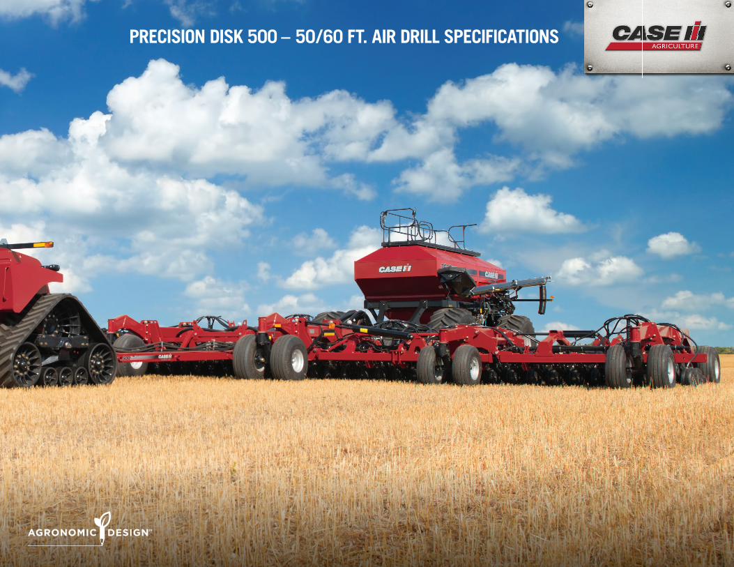
PRECISION DISK 500 – 50 / 60 FT. AIR DRILL SPECIFICATIONS

PROD
UCT
SPE
CIFI
CATI
ONS
PRECISION DISK 500 – 50 / 60 FT. AIR DRILL SPECIFICATIONS• Better emergence and better stands in a range of soil conditions
• Improved seed placement from parallel-link row unit system with new seed tube and scraper, combined with variable down-pressure springs and hydraulic rank pressure control
• Single disk design tackles heavy residue and yield-robbing hair pinning
• Double-edge closing wheel ensures good seed-to-soil contact
• Seed at higher � eld speeds depending on soil and residue conditions
• New 50 and 60 ft. sizes for greater productivity
PRECISION DISK 500 50 FT. (15.24 M) 60 FT. (18.29 M)
CONFIGURATIONSTank Style Tow Behind or Tow Between Air CartRow Spacing 10 in. (25.4 cm) Standard or 7.5 in. (19.05 cm) OptionalFRAME
Weight (Empty) Est.7.5 in. – 40,000 lbs. (18 143 kg) 7.5 in. – 45,500 lbs. (20 639 kg)10 in. – 36,600 lbs. (16 601 kg) 10 in. – 41,500 lbs. (18 824 kg)
Fold Type Double FoldWing Flex 5 Section Flex (10° Down & 15° Up)Hitch FloatingTransport Height 13.2 ft. (4.02 m) 14.8 ft. (4.5 m)Transport Width 18.7 ft. (5.7 m) 18.7 ft. (5.7 m)
Tire Package – Standard
Stubble Resistant Tires All Locations. Quantity: 20 Total WheelsSingle 12.5L – 15 D ply rating tires on outer wings
Fixed tandem 12.5L – 15 D ply rating tires on inner wingsWalking tandem 16.5 × 16.1 E ply rating tires on center section
Tire Package – High Floatation (Optional)Stubble Resistant Tires All Locations. Quantity: 24 Total Wheels
Walking tandem 12.5L – 15 D ply rating tires on inner and outer wingsWalking tandem 16.5 × 16.1 E ply rating tires on center section
METERING / MONITORINGMeter Drive System Air Cart Dependent (Mech or Hyd Drive)Display System AFS Pro 700 or ISO11783 Compliant DisplayFlow Monitor Optional Primary Run Monitoring or Optional Secondary Run Monitoring
Extended Wear Distribution Optional
ROW UNIT / OPENER
Minimum PTO HP Requirement10 in. – 228 HP** 10 in. – 274 HP**7.5 in. – 304 HP** 7.5 in. – 365 HP**
Operating Speed 5 – 8 mph (8 – 12.7 kph)Depth Adjustment Per Opener 0 – 3.5 in. (0 – 8.9 cm) 14 Increments with Single "T" HandleRow Unit Vertical Travel (from surface) 8.5 in. up (21.6 cm); 11.5 in. down (29.2 cm)Road-To-Opener Clearance 8.5 in. up (21.6 cm)Row Unit Spring Down Pressure 160 – 400 lbs. (73 kg – 181 kg)Rank Down Pressure Adjustment per Row Single Point Hydraulic (Optional In-Cab) – 200 – 1 400 psiOpening Disk 18 in. (45.72 cm) Single Bevel at 7°Closing System Double Edge, Single WheelClosing System Pressure 3 Settings 59, 71, and 84 lbs. (27, 32, 38 kg)
**Additional horsepower is required to tow and operate the air cart. Minimum requirements are a starting point only and should be increased based on operating conditions in the field, road transport conditions, and other implements that are used with the drill.
SAFETY NEVER HURTS!™ Always read the Operator’s Manual before operating any equipment. Inspect equipment before using it, and be sure it is operating properly. Follow the product safety signs, and use any safety features provided. CNH America LLC reserves the right to make improvements in design and changes in speci� cations at any time without notice and without incurring any obligation to install them on units previously sold. Speci� cations, descriptions and illustrative material herein are as accurate as known at time of publication, but are subject to change without notice. Availability of some models and equipment builds varies according to the country in which the equipment is used.©2013 CNH America LLC. All rights reserved. Case IH is a registered trademark of CNH America LLC. Any trademarks referred to herein, in association with goods and/or services of companies other than CNH America LLC, are the property of those respective companies. Printed in U.S.A. www.caseih.com CIH08071301