Precision CNC Micro Milling & Drilling...
30
Treat Enterprises, Inc. Presents Precision CNC Micro Milling & Drilling Centers Model E-Machine User & Technical Manual
-
Upload
truongtram -
Category
Documents
-
view
225 -
download
0
Transcript of Precision CNC Micro Milling & Drilling...
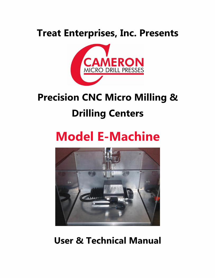
Treat Enterprises, Inc. Presents
Precision CNC Micro Milling &
Drilling Centers
Model E-Machine
User & Technical Manual

CNC-E Micro Machining Center - User & Technical Manual
December 2013 Cameron is a Division of Treat Enterprises, Inc. Page 2
© 2003-2011 by Treat Enterprises, Inc.
All international rights reserved
Reproduction only with written permission of the Management of Treat Enterprises, Inc.
NOTICE
This document contains information, which is proprietary to Treat Enterprises, Inc. It is
prohibited to use the information in this document other than for using the equipment
described. In addition, the products described herein may be protected by one or more
U.S. patents or patents pending.
A trademark of Treat Enterprises, Inc
Other trademarks and trade names used herein refer only to the entities claiming ownership of them. Treat
Enterprises, Inc. claims no proprietary interest in these trademarks or association with their owners.
This Documentation is provided "AS IS". The safe use of the equipment described within is the sole
responsibility of the Owner.
Use by U.S. Governmental entities is subject to all applicable restrictions.

CNC-E Micro Machining Center - User & Technical Manual
December 2013 Made with Pride in the USA Page 3
TABLE OF CONTENTS
TABLE OF CONTENTS ..................................................................................................................................... 3
1. ABOUT THIS MANUAL ............................................................................................................................. 5 1.1 Definition of Terms ....................................................................................................................... 7
2. INTRODUCTION ........................................................................................................................................ 8 2.1 Key Features .................................................................................................................................. 9 2.2 Optional Equipment & Accessories ............................................................................................... 9 2.2.1 VEF 100 ........................................................................................................................................ 9
2.2.2 Fourth Axis .................................................................................................................................... 9
2.2.3 Process Inspection Camera .......................................................................................................... 10
2.2.4 Powder Coated Worktable ........................................................................................................... 10
2.2.5 Granite Base ................................................................................................................................ 10
3. INSTALLATION ....................................................................................................................................... 11 3.1 Electrical Requirements ............................................................................................................... 11 3.2 Dimensions .................................................................................................................................. 11 3.3 Uncrating the System ................................................................................................................... 12 3.4 Moving the Machine .................................................................................................................... 12 3.5 Wire Numbering List for E-machine ........................................................................................... 13 3.6 Set-up Procedure.......................................................................................................................... 13 3.8 Changing Tools ............................................................................................................................ 15 3.12 Mounting the Work Piece ............................................................................................................ 15
4. OPERATIONAL SET-UP .......................................................................................................................... 16 4.1 Safety Precautions ....................................................................................................................... 16 4.2 Safety Features ............................................................................................................................. 17 4.2.1 Safety Covers ............................................................................................................................... 17
4.2.2 EPO (Emergency Power Off) Switch........................................................................................... 17 4.3 Preparing the FlashCut Controller & Start-up .......................................................................... 17 4.4 Using the FlashCut Software .................................................................................................... 18 4.5 Operating the CNC ...................................................................................................................... 20 4.6 Work Piece Change out ............................................................................................................... 20 4.7 Shutdown ..................................................................................................................................... 20 4.8 Storage ......................................................................................................................................... 21
5. MAINTENANCE ...................................................................................................................................... 21 5.1 Lubrication of the Leads Screws and Rails .................................................................................. 21 5.2 Collet Removal ............................................................................................................................ 22 5.3 Adjustments ................................................................................................................................. 23 5.3.1 Set Program Zero ......................................................................................................................... 23
5.3.2 Tool Offset Procedure ................................................................................................................. 24
5.3.3 Setting Up Optional Equipment ................................................................................................... 24
6. TROUBLESHOOTING .............................................................................................................................. 24 6.1 Alarms ......................................................................................................................................... 25
7. REPLACEMENT PARTS LIST .................................................................................................................. 25
8. TECHNICAL SERVICE ............................................................................................................................. 26 8.1 How to Get Technical Support .................................................................................................... 26
9. OUR WARRANTY ................................................................................................................................... 27

CNC-E Micro Machining Center - User & Technical Manual
December 2013 Cameron is a Division of Treat Enterprises, Inc. Page 4
10. THIRD PARTY DOCUMENTATION .......................................................................................................... 28
11. PROGRAM DISKETTES/CDS .................................................................................................................. 28
12. A SPACE FOR YOUR OWN NOTES ......................................................................................................... 29
13. INDEX ..................................................................................................................................................... 30

CNC-E Micro Machining Center - User & Technical Manual
December 2013 Made with Pride in the USA Page 5
1. ABOUT THIS MANUAL
What you will find:
OPERATION
All the information necessary to safely and predictably operate the system is
included in this manual. Operators should be familiar with the information in this
manual before operating the system.
INSTALLATION
Detailed installation procedures for the system and its accessories, including power
and space requirements.
SAFETY
The proper and safe operation of this machine, safety tips and safety systems are
included in this manual.
MAINTENANCE
Maintenance and Adjustment sections are included for ease of maintenance and
periodic adjustment scheduling.
TROUBLESHOOTING
A troubleshooting section is included. This section is limited to simple checks and
fixes an operator can make. Any troubleshooting activities beyond those listed in
this section should not be attempted without input from a Treat Enterprises, Inc.
representative.
RECOMMENDED SPARE PARTS
A recommended spare parts list is included. Stocking these parts at your facility
may reduce downtime.
CNC-E Micro Machining Center - User & Technical Manual
December 2013 Cameron is a Division of Treat Enterprises, Inc. Page 6
NOTICE
OPERATORS MUST READ THE SAFETY TIPS AND WARNINGS CONTAINED IN THESE BOXES. EACH
WILL BE ACCOMPANIED BY ONE OF THE FOLLOWING HEADINGS:
DANGER
THIS HEADING INDICATES AN IMMINENTLY HAZARDOUS SITUATION THAT, IF NOT AVOIDED,
WILL RESULT IN DEATH OR SEVERE INJURY.
WARNING
THIS HEADING INDICATES A POTENTIALLY HAZARDOUS SITUATION WHICH, IF NOT AVOIDED,
COULD RESULT IN DEATH OR SEVERE INJURY.
CAUTION THIS HEADING INDICATES A POTENTIALLY HAZARDOUS SITUATION WHICH, IF NOT AVOIDED,
COULD RESULT IN MODERATE OR MINOR INJURY
CAUTION
THIS HEADING INDICATES A POTENTIALLY HAZARDOUS SITUATION WHICH, IF NOT AVOIDED,
COULD RESULT IN PROPERTY DAMAGE.
NOTICE
THIS HEADING INDICATES A HELPFUL TIP.

CNC-E Micro Machining Center - User & Technical Manual
December 2013 Made with Pride in the USA Page 7
1.1 Definition of Terms
The following words and phrases may be a part of the language used at
your facility. If a word or phrase is not familiar to the reader, its definition
should be found here.
Base: The aluminum plate, to which the CNC and its safety enclosure are
attached.
VEF: Video Edge Finder
PIC: Process Inspection Camera
FlashCut™: The CNC Controller, made by FlashCut™ CNC, Inc.
CAUTION
USING CNC MACHINERY REQUIRES KNOWLEDGE AND EXPERIENCE! TO
USE A CNC MACHINE, YOU MUST KNOW HOW TO USE IT AND
UNDERSTAND G-CODE CNC SOFTWARE. MISUSE VOIDS THE
WARRANTY!

CNC-E Micro Machining Center - User & Technical Manual
December 2013 Cameron is a Division of Treat Enterprises, Inc. Page 8
2. INTRODUCTION
T h a n k Y o u f o r P u r c h a s i n g t h e
C a m e r o n C N C M i c r o M i l l i n g & D r i l l i n g C e n t e r
M o d e l E - M a c h i n e
Cameron CNC Micro Milling & Drilling Centers are ultra-precision small-hole drilling
and drilling/milling machines with speeds up to 30,000 rpm
You will appreciate the ultra-precision and easy operation of Cameron CNC Micro
Milling & Drilling Centers.
The Cameron Product Line was designed with all the critical areas of drilling and milling
center performance:
Rigidity (sturdy gussets and plates support the X-Y table and spindle head)
Concentricity (of spindle rotation with related parts)
Parallelism (all parallel planes are precisely aligned and mounted to remain so)
'Squareness' (the X-Y table and spindle positions are absolutely square to each
other, providing precise performance).
Our goal is to produce affordable systems with unequaled quality and precision.
All Models of Cameron CNC Micro Milling & Drilling Centers have incorporated in
them unique features to meet or exceed the many varied applications of our Customers.
Manufactured with pride in the USA since 1964.
50 years of Successful Small Hole Drilling!
CNC-E Micro Machining Center - User & Technical Manual
December 2013 Made with Pride in the USA Page 9
2.1 Key Features
2.1.1 Model E-Machine Micro Drilling Center
X, Y & Z Axis travel: X=6” Y=4” Z=4”
Axis repeatability is 0.0005” (0.0127mm)
30,000 RPM
Up to 30 IPM feed rates
G-Code Software
NEMA 23 Stepper Motors for Each Axis
125W Brushless DC Motor on Spindle
Spindle run-out within 1 UM
Linear Guide Rails
Acme thread .0625” Pitch Lead Screw
Precision Collet System with ⅛” Collet standard (1mm to
6mm in increments of .1mm, and also ¼” (.250”)
Safety Enclosure with a 2” dia. Vacuum Nozzle
2.2 Optional Equipment & Accessories
The optional equipment listed below may be purchased for any Cameron
CNC System.
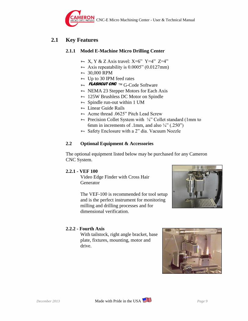
2.2.1 - VEF 100
Video Edge Finder with Cross Hair
Generator
The VEF-100 is recommended for tool setup
and is the perfect instrument for monitoring
milling and drilling processes and for
dimensional verification.
2.2.2 - Fourth Axis
With tailstock, right angle bracket, base
plate, fixtures, mounting, motor and
drive.
CNC-E Micro Machining Center - User & Technical Manual
December 2013 Cameron is a Division of Treat Enterprises, Inc. Page 10
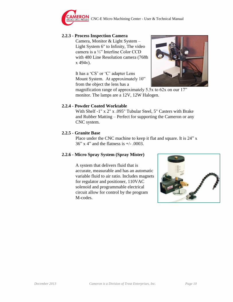
2.2.3 - Process Inspection Camera
Camera, Monitor & Light System –
Light System 6" to Infinity, The video
camera is a ⅓” Interline Color CCD
with 480 Line Resolution camera (768h
x 494v).
It has a ‘CS’ or ‘C’ adapter Lens
Mount System. At approximately 10”
from the object the lens has a
magnification range of approximately 5.5x to 62x on our 17”
monitor. The lamps are a 12V, 12W Halogen.
2.2.4 - Powder Coated Worktable
With Shelf -1" x 2" x .095" Tubular Steel, 5" Casters with Brake
and Rubber Matting – Perfect for supporting the Cameron or any
CNC system.
2.2.5 - Granite Base
Place under the CNC machine to keep it flat and square. It is 24” x
36” x 4” and the flatness is +/- .0003.
2.2.6 - Micro Spray System (Spray Mister)
A system that delivers fluid that is
accurate, measurable and has an automatic
variable fluid to air ratio. Includes magnets
for regulator and positioner, 110VAC
solenoid and programmable electrical
circuit allow for control by the program
M-codes.

CNC-E Micro Machining Center - User & Technical Manual
December 2013 Made with Pride in the USA Page 11
3. INSTALLATION
The Cameron CNC Micro Milling & Drilling Center is a stand-alone system
requiring only connection to the proper power and air for operation.
CAUTION
USING CNC MACHINERY REQUIRES KNOWLEDGE AND EXPERIENCE! TO USE A
CNC MACHINE, YOU MUST KNOW HOW TO USE IT AND UNDERSTAND G-CODE
CNC SOFTWARE. MISUSE VOIDS THE WARRANTY!
3.1 Electrical Requirements
Nominal 110 VAC, 50-60 HZ @ 5 Amperes. A power transformer will be
required where 240V is used.
WARNING
ALWAYS CONNECT THE POWER CABLE TO THE MACHINE FIRST! DO NOT
CONNECT THE POWER CABLE TO ANY POWER SOURCE UNTIL THE
MACHINE IS IN ITS FINAL LOCATION, ALL COVERS ARE CLOSED AND ALL
OTHER CONNECTIONS HAVE BEEN MADE!
3.2 Dimensions
E-Machine
Width: 22”
Depth: 24”
Height: 20”
Weight: Approx 120 lbs
The Cameron CNC Micro Milling & Drilling Center is designed for use in
nearly any dry environment. We recommend that you use our optional
Powder Coated Mobile Workstation as a home for the Press.
Cameron CNC Micro Milling & Drilling Centers are designed and
constructed to function in various manufacturing atmospheres. These are
precisely calibrated pieces of equipment. Please try to avoid rough
handling when moving and installing the machine.
Use the following procedure to install the Cameron CNC Micro Milling &
CNC-E Micro Machining Center - User & Technical Manual
December 2013 Cameron is a Division of Treat Enterprises, Inc. Page 12
Drilling Center.
3.3 Uncrating the System
Rest assured your system has been packaged as safely and reasonably as is
possible. We expect the system to be received without damage to it or any
of its parts.
All Cameron equipment is shipped F.O.B. (Freight on Board) Sonora (our
shipping dock).
If upon receipt of your crate(s) you see that there has been damage, such
that you fear the contents may have been damaged, immediately inform
the shipper. They are responsible for bringing the system safely to you.
Please use caution when uncrating the system. At least two people should
be involved, as one person may not be able to handle the weight and size
of the system.
3.4 Moving the Machine
The Cameron CNC Micro Milling & Drilling Center is separated into a
few modules and can be handled by two persons with average lifting
capabilities.
Keep the machine upright and set it down gently on its workbench. We
recommend using the Cameron Powder Coated Mobile Workstation.
Here are some simple moving tips:
At least two persons with average lifting capabilities are required
to move the equipment
Do not tip or jar the equipment
Do not drop the equipment
Do not lift the system by its covers or motors. Lift only from the
bottom plate
CAUTION
WATCH YOUR FINGERS! WHEN SETTING THE CNC DOWN ON ITS BENCH,
MAKE SURE YOU DO NOT SET THE MACHINE ON YOUR FINGERS!
ALTHOUGH THE UNIT IS NOT HEAVY ENOUGH TO CAUSE DAMAGE TO
YOU, IT MAY CAUSE PAIN IF LOWERED ONTO A FINGER OR HAND.
Do not open crate in a dusty or moist place.
Inspect the equipment immediately for obvious damage from

CNC-E Micro Machining Center - User & Technical Manual
December 2013 Made with Pride in the USA Page 13
shipping.
Be sure the table or bench is sturdy enough to hold the CNC (120lbs).
3.5 Wire Numbering List for E-machine All Power cords plug to a power strip for on/off operation
USB plug into a computer
Spindle controlled manually – see Spindle Control Manual
Spray Mister controlled manually – see Spray Mister manual
VEF/PIC controlled manually
3.6 Set-up Procedure
1. Please read the manual for complete operating instructions before
operating your Cameron CNC Center.
2. Remove the CNC Machine from the carton. Place the CNC Machine
on a sturdy, level surface.
3. Plug CNC power source into power strip. Turn Power Strip on.
4. For units with the PIC:
5. Remove the Process Inspection Camera from its carton.
6. Assemble the camera.
7. Connect the video cable (#7) for the process inspection camera to the
VEF/PIC switch box.
8. Connect the video cable (#5) from the VEF/PIC switch box to the
monitor.
9. Connect the power supply (#6) to the PIC. Plug the power supply into
the Power Strip. If you want to prolong the life of the camera, only
plug it in when needed.
10. To see images from the Process Inspection Camera, switch the
VEF/PIC switch box to ‘PIC”.
CNC-E Micro Machining Center - User & Technical Manual
December 2013 Cameron is a Division of Treat Enterprises, Inc. Page 14
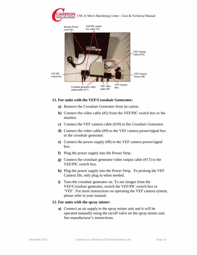
11. For units with the VEF/Crosshair Generator:
a) Remove the Crosshair Generator from its carton.
b) Connect the video cable (#5) from the VEF/PIC switch box to the
monitor.
c) Connect the VEF camera cable (#10) to the Crosshair Generator.
d) Connect the video cable (#9) to the VEF camera power/signal box
to the crosshair generator.
e) Connect the power supply (#8) to the VEF camera power/signal
box.
f) Plug the power supply into the Power Strip.
g) Connect the crosshair generator video output cable (#17) to the
VEF/PIC switch box.
h) Plug the power supply into the Power Strip. To prolong the VEF
Camera life, only plug in when needed.
i) Turn the crosshair generator on. To see images from the
VEF/Crosshair generator, switch the VEF/PIC switch box to
‘VEF’. For more instructions on operating the VEF camera system,
please refer to your manual.
12. For units with the spray mister:
a) Connect an air supply to the spray mister unit and it will be
operated manually using the on/off valve on the spray mister unit.
See manufacturer’s instructions.

CNC-E Micro Machining Center - User & Technical Manual
December 2013 Made with Pride in the USA Page 15
3.8 Changing Tools 1. Set the 12mm wrench on the spindle.
2. Place the 14mm wrench on the chuck
nut and turn it counterclockwise to
loosen the collet and remove the
cutting tool. (The first turn will loosen
the chuck nut, but the tool will not
release and turning will become stiff.
3. Insert the new tool and tighten the
collet by turning clockwise.
CAUTION
NEVER TIGHTEN THE COLLET WITHOUT MOUNTING A CUTTING TOOL AS
THIS WILL RESULT IN DAMAGE TO THE COLLET, SPINDLE AND COLLET
NUT AND MAKE IT IMPOSSIBLE TO REMOVE THE COLLET. THIS ALSO
VOIDS THE MANUFACTURER’S WARRANTY
3.12 Mounting the Work Piece
1. Your CNC may have been delivered with a work piece-mounting fixture,
which has been installed on the standard mounting plate. Refer to the
System Specification Sheet supplied with your system for details.
2. If your system does not have a custom-built plate, the standard mounting
plate is installed. The standard plate is 5.5” x 6” and is equipped with
10-32 tapped holes on 1” centers (where there is no interference).
3. Your mounting fixture should be made to adapt to this hole pattern.
CAUTION
NEVER LOOSEN THE BOLTS HOLDING THE MODULES TOGETHER AND TO
THE BASE PLATE. THIS MAY CAUSE THE SYSTEM TO BECOME
MISALIGNED. LOOSENING THE BOLTS VOIDS THE WARRANTY!
CAUTION
4TH AXIS SAFETY PRECAUTIONS
WHEN SETTING UP THE 4TH AXIS UNIT, CARE MUST BE TAKEN TO SET IT
SO THE MOTOR WILL NOT CONTACT THE SAFETY COVER WHEN THE X-Y

CNC-E Micro Machining Center - User & Technical Manual
December 2013 Cameron is a Division of Treat Enterprises, Inc. Page 16
TABLE IS MOVED TO THE RIGHT (THE HOME END OF THE X AXIS) OR IN
THE NEGATIVE DIRECTION. THE SAFETY COVER FRONT DOOR HAS A
SLOT TO PROTRUDE OUTSIDE THE SAFETY DOOR.
WHEN SETTING UP THE 4TH AXIS, MOVE THE X AXIS TO ITS FAR RIGHT
(HOME) BEFORE ATTACHING THE 4TH AXIS TO THE CNC TABLE TOP. SET
THE 4TH AXIS TO ALLOW THE SPINDLE HEAD TO CLEAR THE 4TH AXIS
CHUCK DURING PART MACHINING. THIS WILL ENSURE THAT THE MOTOR
WILL NOT CONTACT THE SAFETY COVER DOOR DURING ANY MACHINE
TRAVEL.
4. OPERATIONAL SET-UP
The following sections explain how to safely set the system up for operation.
4.1 Safety Precautions
The first and most critical step toward the safe and efficient operation of
this or any other piece of equipment is to READ AND UNDERSTAND
ALL SECTIONS OF THIS MANUAL prior to operating the equipment.
We know you plan to follow all of the safety precautions required by the
machine’s owner as well as state, federal and local codes. In addition to
the rules of common sense the following safety rules should also be
known:
Keep extremities, hair, clothing, jewelry or other personal items
that may get caught up in the moving parts of the machine away
from those parts whenever the machine is running.
Long hair should be tied back while operating or standing
close to an operating machine.
Do not wear loose clothing or dangling jewelry while operating or
standing close to an operating machine.
Do not insert any object, other than the material for which the
machine was constructed to process, into the machine at any point.
The machine must never be operated with safety covers removed.
Even though machine power is switched OFF, dangerous voltages
are still present within the control enclosure.

CNC-E Micro Machining Center - User & Technical Manual
December 2013 Made with Pride in the USA Page 17
Disconnect the machine from the AC power line prior to
removing any cover! The law and common sense dictate that
this machine must be de-energized prior to maintenance or
repair. Keep the line cord under your control after
disconnection.
4.2 Safety Features
The Cameron CNC Micro Milling & Drilling Center has the following
built-in safety features:
4.2.1 Safety Covers Panels through which access to electrical dangers are possible can
only be opened with a tool.
An acrylic safety shield is provided around the drill center for
protection of the operator.
The CNC shield has hinged access panels, which do not shut the
system down when opened.
WARNING
NEVER OPEN THE ACCESS DOORS WHILE THE CNC IS IN OPERATION!
WITHIN THE SAFETY COVER ARE PINCH POINTS, CUTTING POINTS AND
ELECTRICAL HAZARDS. ALWAYS SHUT DOWN POWER TO THE ENTIRE
SYSTEM PRIOR TO ACCESSING THE CNC’S INTERIOR.
4.2.2 EPO (Emergency Power Off) Switch
A Red EPO switch is located on the Spindle Control Box. It may
be pushed in to immediately stop the X, Y, & Z motors from
moving.
WARNING
PUSHING IN THE EPO BUTTON DOES NOT REMOVE POWER FROM THE
ENTIRE SYSTEM. THERE IS STILL ELECTRICAL POWER INSIDE THE
CONTROL ENCLOSURE AND THE CNC AFTER THE EPO IS ACTIVATED.
4.3 Preparing the FlashCut Controller & Start-up
If you have questions about the FlashCut Software, refer to the

CNC-E Micro Machining Center - User & Technical Manual
December 2013 Cameron is a Division of Treat Enterprises, Inc. Page 18
manual(s) included or call FlashCut’s Technical Service at:
Phone: (847) 940-9305 (9am to 5pm, CST, M-F)
Fax: (847) 940-9315
Email: [email protected]
Web site: www.flashcut.com
The following procedure is for setting up and starting operation on the
Cameron CNC Micro Milling & Drilling Center and FlashCut
Controller. Assuming you have made all the proper connections, mounted
the work piece and bit, and power is available throughout the system
(including the light, camera and monitor), you may begin the process of
preparing the FlashCut controller for operation.
Use this sequence to set up the FlashCut Program:
Step 1 For E-Machine, turn power strip on and check that e-stop is
pulled up.
Step 2 If the system has not yet opened the FlashCut program; simply
select the appropriate icon on the desktop window of the
computer.
Here you will be asked certain questions in pop-up windows:
Q.1 Reset to Previous values? Answer YES.
Q.2 Do you accept the safety message? Answer YES.
(After you have read and understand the message!)
Step 3 Ensure that the computer is “online” or “connected” with the
drilling system. If it is offline, go online, or the system will not
respond.
Step 4 Set the tool offset. Select file tab on top of screen. Select open G
code tab, find the file you wish to run, select it and click open
tab. Select the G code tab, and select the start tab.
Step 5 Select the Start key again. The program will begin and,
assuming you have loaded the work piece correctly, start drilling
or milling.
Step 6 Make a Test Run without the Drill Bit or Milling Cutter
4.4 Using the FlashCut Software

CNC-E Micro Machining Center - User & Technical Manual
December 2013 Made with Pride in the USA Page 19
If you have purchased a pre-programmed and pre-set system from Treat
Enterprises, a program readout and disc are included elsewhere in this
binder. There should be no need for any reprogramming on your part.
However, once you have powered up the laptop and accessed the
FlashCut software, you can perform certain tasks from the main screen,
which will not affect the program, but may be useful to the operator.
A copy of the manuals provided by FlashCut software and hardware can
be found on the laptop computer sent with the unit. Please read that
manual prior to attempting any process, other than those described in the
previous section and the few functions listed below. You will not be able
to use these functions while the machine is in the middle of a process run.
You will need to stop the current process.
Jog: The Jog function allows the user to move the X-Y-Z Plate in any
direction, in pre-set increments. When you select the Jog key, a window
will open allowing this function. The screen has a display showing you
the position of the X-Y table at all times.
Point to Point: The Point to Point function allows the user to move the
base from one specific, precise position to another. When you select the
Point-to-Point key, a window will open allowing this function.
Home: The Home function allows the user to move the base to the
programmed Home position. When you select the Home key, a window
will open allowing this function.
Aux: The Aux function allows the user to turn auxiliary devices (such as
the Spindle Motor) on or off. When you select the Aux key, a window
will open, showing the auxiliary devices controlled here and allowing this
function. Not applicable to the E-Machine as shipped.
CNC-E Micro Machining Center - User & Technical Manual
December 2013 Cameron is a Division of Treat Enterprises, Inc. Page 20
4.5 Operating the CNC
CAUTION
USING CNC MACHINERY REQUIRES KNOWLEDGE AND EXPERIENCE! TO
USE ANY CAMERON CNC MACHINE, YOU MUST KNOW HOW TO OPERATE
A CNC AND UNDERSTAND G-CODE CNC SOFTWARE. MISUSE VOIDS THE
WARRANTY!
DO NOT USE FLOOD COOLANT METHODS ON THE CNC. NEVER GET
COOLANT ON ANY MOTOR! WE RECOMMEND USING A LIGHT SPRAY
COOLANT OR AIR COOLING.
Assuming you have mounted the correct work piece properly, the program
is written and ready for use and the proper drill bit or cutter is installed,
you may proceed to process parts.
Simply select the Start key on the main FlashCut screen on the laptop.
Refer to the FlashCut manual provided with the system for more
information about using that program.
4.6 Work Piece Change out
If the work piece-mounting fixture was designed and built at the factory,
refer to the System Specification Sheet for information.
WARNING
ALWAYS SHUT DOWN THE POWER TO THE MACHINE FIRST! DO NOT
ATTEMPT TO REMOVE OR INSTALL A WORK PIECE WITH POWER ON!
4.7 Shutdown
When you have finished the job at hand, shutting down the system is
simple. When the job cleanup tasks are complete, according to the rules of
your facility, we recommend the following machine-specific cleanup and
maintenance.
Step 1 Check all lead screws for mineral oil and re-apply if required.
NOTICE
WE RECOMMEND THAT YOU SET THE COMPUTER TO THE ‘OFFLINE’
STATE PRIOR TO PUTTING THE LAPTOP IN SLEEP MODE. THIS FORCES
THE NEXT USER TO GO ‘ONLINE’ AT THE NEXT START UP. GOING ONLINE
AT EACH POWER-UP ENSURES A PROPER CONNECTION TO THE DRILL.
CNC-E Micro Machining Center - User & Technical Manual
December 2013 Made with Pride in the USA Page 21
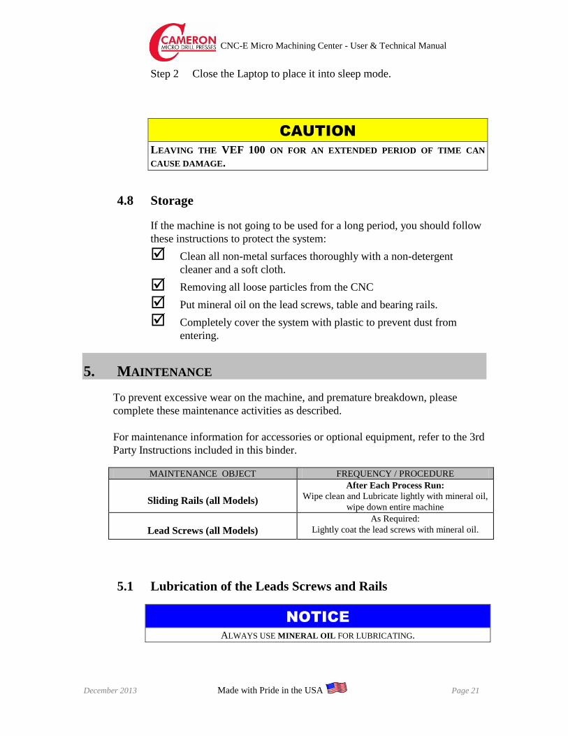
Step 2 Close the Laptop to place it into sleep mode.
CAUTION
LEAVING THE VEF 100 ON FOR AN EXTENDED PERIOD OF TIME CAN
CAUSE DAMAGE.
4.8 Storage
If the machine is not going to be used for a long period, you should follow
these instructions to protect the system:
Clean all non-metal surfaces thoroughly with a non-detergent
cleaner and a soft cloth.
Removing all loose particles from the CNC
Put mineral oil on the lead screws, table and bearing rails.
Completely cover the system with plastic to prevent dust from
entering.
5. MAINTENANCE
To prevent excessive wear on the machine, and premature breakdown, please
complete these maintenance activities as described.
For maintenance information for accessories or optional equipment, refer to the 3rd
Party Instructions included in this binder.
MAINTENANCE OBJECT FREQUENCY / PROCEDURE
Sliding Rails (all Models)
After Each Process Run:
Wipe clean and Lubricate lightly with mineral oil,
wipe down entire machine
Lead Screws (all Models)
As Required:
Lightly coat the lead screws with mineral oil.
5.1 Lubrication of the Leads Screws and Rails
NOTICE
ALWAYS USE MINERAL OIL FOR LUBRICATING.

CNC-E Micro Machining Center - User & Technical Manual
December 2013 Cameron is a Division of Treat Enterprises, Inc. Page 22
The length of time between lubrication will vary according to use. If there is any
squeaking during movement it is time to lubricate the screws and rails. It is
easiest if you use a squeeze bottle or an oilcan with a long spout in order to reach
the areas needed.
To apply oil to the X and Y lead screws and rails, jog the table to one end of
travel. Lift up the way cover and apply oil to the screw. Reach in toward the anti-
backlash nut and coat the screw along its full length. Also apply oil to the radius
grooves that run along both sides of the rail. Jog the table to the other side, using
low or medium speed, and repeat the process.
Apply oil to the Z lead screw and rails and raise the spindle head to the top of the
travel. Coat the lower section of the screw with oil. Also apply oil to the radius
grooves that run along both sides of the rail. Jog the head down, using low or
medium speed, and repeat the process.
5.2 Collet Removal
The following procedure should be completed when removing or replacing
the collet. No tools are required for this procedure other than those
supplied with the CNC.
WARNING
UNPLUG THE UNIT FROM ITS POWER SOURCE BEFORE BEGINNING
REMOVAL. SAFETY DICTATES REMOVAL OF POWER SOURCE AS THE
FIRST STEP.
1. Remove the cutting tool according
to section ‘3.8 Changing Tools’
and remove the chuck nut
assembly.
2. The collet and chuck nut are held
together by a groove in the collet
and a flange in the chuck nut. To
remove the collet, hold the chuck
nut in one hand and push
diagonally down on the collet.
The collet should pop out.
3. Install the new collet in the chuck nut by positioning the collet in the
chuck nut and pressing down on a flat surface.

CNC-E Micro Machining Center - User & Technical Manual
December 2013 Made with Pride in the USA Page 23
CAUTION
NEVER INSTALL A COLLET INTO THE SPINDLE QUILL WITHOUT FIRST
ASSEMBLING IT IN THE CHUCK NUT.
WARNING
CLOSING THE COLLET WITHOUT A TOOL OR PIN INSERTED GREATLY
REDUCES THE LIFE EXPECTANCY OF THE COLLET. THIS ALSO VOIDS THE
MANUFACTURER’S WARRANTY.
5.3 Adjustments The following adjustment procedures can be made to the machine as
deemed necessary by the manager or maintenance person responsible for
machine operation.
When the machine was delivered, all of these adjustments were set to the
optimal operating condition. No further adjustment should be necessary,
unless there has been a change in the materials used or a component has
been moved out of adjustment.
NOTICE
NO ADJUSTMENTS, OTHER THAN THOSE DESCRIBED BELOW, ARE TO BE
MADE ON THE CAMERON CNC MICRO MILLING & DRILLING CENTER
WITHOUT TREAT ENTERPRISES ENGINEERING INPUT.
DANGER
HUMAN INJURY RISK! REMOVE ALL POWER FROM THE MACHINE
PRIOR TO MAKING ANY OF THE FOLLOWING ADJUSTMENTS. FAILURE TO
DO SO CAN RESULT IN HUMAN INJURY.
5.3.1 Set Program Zero
To set the program zero use the VEF to find the two edges of the
part if rectangular or square. For a round part find the outside edge
with the VEF. Move the part ½ the diameter toward the center of
the part. Repeat the process for the other axis. Double check to
verify you are on center line.
Move the part to adjust for the VEF center to the drill center line.
These values are on the Cameron Q&A checklist, located at the
CNC-E Micro Machining Center - User & Technical Manual
December 2013 Cameron is a Division of Treat Enterprises, Inc. Page 24
beginning of this manual.
Right click the mouse in the machine coordinate area, pick the
define fixture offset. Make sure only X and Y axis are selected.
Pick set. Click ok to reset.
You can if you prefer set X and Y program coordinates to zero in
the program coordinate box.
You are ready to run a program.
5.3.2 Tool Offset Procedure
1. Load tool into collet making sure the flutes of the drill extend
below the face of the video edge finder.
2. Jog the tool above the part you want to set the tool to.
3. Turn on the spindle.
4. Carefully jog the tool down to the top of the part until the drill
just touches. Use the process inspection camera to determine
when you are at the top of the part.
5. Right click in the machine coordinate area and pick the define
tool offset to open a window. In the use DRO box, set to
machine. In the set access box set Z-only. Select the correct
tool number and pick set.
6. FlashCut will let you know you have made a configuration
change and the program will need to be reset, do you want to
proceed? Click the ok button.
7. Jog the tool up off of the part to a safe distance.
5.3.3 Setting Up Optional Equipment
Please refer to the manuals provided in this binder for instructions
on adjusting optional equipment and accessories.
6. TROUBLESHOOTING
The troubleshooting activities listed below are limited to the simple things an
operator can do to try to address a problem with the machine.
PROBLEM WHERE TO LOOK
The machine will not turn on when the
power strip is turned on
1. The EPO button is not pulled out (up).
2. Check to see if FlashCut is on line

CNC-E Micro Machining Center - User & Technical Manual
December 2013 Made with Pride in the USA Page 25
Power is “on”, but the CNC will not
run
1. Check the connections from the
control enclosure to the CNC.
Drill will not run, although power is
available and the program is running
correctly
1. Check the speed control on the control
enclosure.
Machine stops mid-run
1. Check if the x-y table is resting over a
limit switch – if yes; jog the table until
it is free.
2. Check power
3. Check computer
Drills holes off-center 1. Refer to VEF 100 manual
Drill will not run
1. Check to make sure that the
‘Auto/Manual’ switch on the spindle
control panel is set to ‘manual’.
6.1 Alarms
The FlashCut program will send certain ‘warning messages’ to the
screen to alert the operator of machine and program issues. The alarms
that may pop up have been determined by Treat Enterprises. For a listing
of possible warning messages, see the FlashCut CNC User’s Guide.
The spindle will send error codes to the spindle control screen. Refer to the
label on the side of the control box for error code information. Correct the
problem and press the reset button to clear the error code.
7. REPLACEMENT PARTS LIST
The following is a partial list of replacement parts., Parts are available at the
factory, please call for pricing.
Part # Description
CNC102-3 Y-Axis Lead Screw (8.5”, 16 TPI)
CNC103-1 X-Axis Lead Screw (9.8”, 16 TPI)
CNC104-3 Z-Axis Lead Screw (14.7”, 16 TPI)
CNC105 Super Nut
CNC109 Flex Coupling
CNC110 Limit Switch
CNC111 Way Cover (Set)
CNC112 X-Axis Linear Rail Guide (Set)
CNC113 Z-Axis Linear Rail Guide (Set)
CNC114 Y-Axis Linear Rail Guide (Set)
CNC125 Stepper Motor
CNC-E Micro Machining Center - User & Technical Manual
December 2013 Cameron is a Division of Treat Enterprises, Inc. Page 26
8. TECHNICAL SERVICE
Cameron CNC Micro Milling & Drilling Centers have been designed and
constructed using the highest quality standards. However, should your unit fail to
function properly, in spite of regular maintenance, and you cannot find the
solution to the issue in the Troubleshooting section of this manual, contact Treat
Enterprises for technical support. Our engineers can probably determine how to
correct the problem, with telephone support.
8.1 How to Get Technical Support
Treat Enterprises provides complete after sale service and support for all
Cameron products.
Our Hours of Operation are:
Monday-Friday 7am-3:30pm Pacific Standard Time
Treat Enterprises observes the following U.S. holidays:
New Year’s Day (1 day)
Memorial Day (1 day)
Independence Day (1 day)
Labor Day (1 day)
Thanksgiving (1 day)
Christmas Day (1 day)
To obtain service, contact Treat Enterprises per Telephone, Fax or Email.
Telephone: ....1-800-369-7769 or (209) 532-7201
Fax: ................(209) 532-1211
Address: ........19401 Rawhide Road, Sonora, CA. 95370
Email: [email protected]
Http: ..............www.cameronmicrodrillpress.com

CNC-E Micro Machining Center - User & Technical Manual
December 2013 Made with Pride in the USA Page 27
9. OUR WARRANTY
Treat Enterprises, Inc. warrants that items of its own manufacture will be free
from defects in material and/or workmanship at the time of delivery and will be so
for a period of 6 months (180 days) after leaving the Treat Enterprises facility. If
any such item proves to be defective (assuming the item has been used and
maintained as intended during the warranty period, which will be determined by
Treat Enterprises), as a first step, Treat Enterprises personnel will attempt to
troubleshoot the issue per phone and other communication with the Customer and
evaluate the need for action. Typically, any parts that fail prematurely are able to
be replaced by the Customer with the guidance of Treat Enterprises personnel, and
Treat Enterprises reserves the right to attempt to solve the issue in this manner
prior to any other warranty activities.
If it is determined that the system or machine, or any part thereof, needs to be
returned to the Treat Enterprises factory for further investigation, a Return
Authorization will be issued. After contacting Treat Enterprises’ Service
Department and receiving Return Authorization, the machine’s Owner is required
to ship the item, freight prepaid, to the Treat Enterprises facility. Final
responsibility for shipping costs will be determined by Treat Enterprises, after
inspection of the part(s) or machine. Treat Enterprises retains the option to repair
or replace the item(s) in question at its own expense.
Warranties on components not manufactured by the Treat Enterprises, but
included and sold as part of the system, are limited to those provided by their
original manufacturers. However, Treat Enterprises will handle returns of those
components as well. The Owner must still ship the component(s) prepaid.
This warranty is expressly limited to the repair or replacement of defective items
as described above. In no event shall Treat Enterprises be held liable or
accountable for incidental or consequential damages due to any breach of
warranty, defect in material, workmanship or omissions/misstatements in this or
any documentation. Treat Enterprises shall not be responsible for repair or
replacement of items which have been subjected to neglect, accident or misuse, or
which have been altered by anyone other than Treat Enterprises personnel.
Treat Enterprises retains all protected, proprietary rights, including patent rights,
rights to devices originated by Treat Enterprises, which are part of the equipment,
and rights to designs or data furnished to the Owner.
An extended Warranty Period of up to One Year is available. Ask our Customer
Service Department or Sales Representatives for details.

CNC-E Micro Machining Center - User & Technical Manual
December 2013 Cameron is a Division of Treat Enterprises, Inc. Page 28
10. THIRD PARTY DOCUMENTATION
The original manufacturers of components, which are not manufactured by Treat
Enterprises, Inc., have supplied some information. These are referred to as “Third
Party Documentation. The information is included in the form it was received by
Treat Enterprises, Inc., with no changes, deletions or additions. Treat Enterprises,
Inc. accepts no responsibility or liability based on the information included in this
3rd party information. If you believe the information is false or not complete,
please contact the manufacturer of the component.
The Third Party Manuals and/or Data Sheets either are bound together with this
manual or have been supplied as part of a complete document package, typically
delivered with the machine.
11. PROGRAM DISKETTES/CDS
Any Diskettes or CDs required to use or configure the system are included in a
Disk Protector found in this binder or provided separately.
CNC-E Micro Machining Center - User & Technical Manual
December 2013 Made with Pride in the USA Page 29
12. A SPACE FOR YOUR OWN NOTES
You may use this page to note any changes made, helpful tips, calibration parameters or
setup information. Use to keep any information not contained in this manual, which an
operator may find useful in the setup and operation of this machine.
________________________________________________________________________
________________________________________________________________________
________________________________________________________________________
________________________________________________________________________
________________________________________________________________________
________________________________________________________________________
________________________________________________________________________
________________________________________________________________________
________________________________________________________________________
________________________________________________________________________
________________________________________________________________________
________________________________________________________________________
________________________________________________________________________
________________________________________________________________________
________________________________________________________________________
________________________________________________________________________
________________________________________________________________________
________________________________________________________________________

CNC-E Micro Machining Center - User & Technical Manual
December 2013 Cameron is a Division of Treat Enterprises, Inc. Page 30
13. INDEX
A
Adjustments Set Program Zero · 23 Tool Offset · 23
Air Diagram · 15
C
Collet Removal · 22
E
Electrical Requirements · 11 EPO (Emergency Power Off) · 17
F
FlashCut Definitions · 19 FlashCut™ Operation · 18–19
M
Maintenance · 21
O
Optional Equipment Fourth Axis · 9 Granite Base · 10
Process Inspection Camera · 9 VEF 100 · 9 Worktable · 10
P
Power · 11, 17, 22
R
Replacement Parts · 25
S
Safety · 16 Features · 17 Precautions · 16
Set-up Machine · 13–14 Shutdown · 20 Storing Machine · 21
T
Technical Service · 26 Tool Installation · 15 Troubleshooting · 24
W
Warranty · 27