
Precision Ball Screws and Lead Screws Catalog (A4) · Precision Screws Ball screws, trapezoidal...
106
www.thomsonlinear.com Precision Screws Ball screws, trapezoidal and lead screws – highest level of performance and quality.
Transcript of Precision Ball Screws and Lead Screws Catalog (A4) · Precision Screws Ball screws, trapezoidal...

www.thomsonlinear.com
Precision ScrewsBall screws, trapezoidal and lead screws – highest level of performance and quality.

Thomson – the Choice for Optimized Motion SolutionsOften the ideal design solution is not about finding the fastest, sturdiest, most accurate or even the least expensive option. Rather, the ideal solution is the optimal balance of performance, life and cost.
The Best Positioned Supplier of Mechanical Motion TechnologyThomson has several advantages that makes us the supplier of choice for motion control technology.• Thomson own the broadest standard product offering of mechanical motion technologies in the industry. • Modified versions of standard product or white sheet design solutions are routine for us. • Choose Thomson and gain access to over 70 years of global application experience in industries including packaging, factory
automation, material handling, medical, clean energy, printing, automotive, machine tool, aerospace and defense. • As part of Fortive Corporation, we are financially strong and unique in our ability to bring together control, drive, motor, power
transmission and precision linear motion technologies.
A Name You Can TrustA wealth of product and application information as well as 3D models, software tools, our distributor locator and global contact informa-tion is available at www.thomsonlinear.com. For assistance in Europe, contact us at +44 1271 334 500 or e-mail us at [email protected] to us early in the design process to see how Thomson can help identify the optimal balance of performance, life and cost for your next application. And, call us or any of our 2000+ distribution partners around the world for fast delivery of replacement parts.
The Fortive Business SystemThe Fortive Business System (FBS) was established to increase the value we bring to customers. It is a mature and successful set of tools we use daily to continually improve manufacturing operations and product development processes. FBS is based on the principles of Kaizen which continuously and aggressively eliminate waste in every aspect of our business. FBS focuses the entire organization on achieving breakthrough results that create competitive advantages in quality, delivery and performance – advantages that are passed on to you. Through these advantages Thomson is able to provide you faster times to market as well as unsurpassed product selection, ser-vice, reliability and productivity.
Local Support Around the Globe
Application Centers Global Design & Engineering CentersGlobal Manufacturing Operations

www.thomsonlinear.com 3
Table of contents
Requirements on a precision screw . . . . . . . . . . . . . . . . . . . . . . . . . . . . . . . . . . . . . . . . . . . . . . . . . . . . . . . . . . . . . . . . . . . . . . . . . . . . . 4
Recirculating ball screws . . . . . . . . . . . . . . . . . . . . . . . . . . . . . . . . . . . . . . . . . . . . . . . . . . . . . . . . . . . . . . . . . . . . . . . . . . . . . . . . . . . . . 6General technical data for recirculating ball screws . . . . . . . . . . . . . . . . . . . . . . . . . . . . . . . . . . . . . . . . . . . . . . . . . . . . . . . . . . . . . . 7Standard manufacturing program . . . . . . . . . . . . . . . . . . . . . . . . . . . . . . . . . . . . . . . . . . . . . . . . . . . . . . . . . . . . . . . . . . . . . . . . . . . . . . . 8Preloading methods . . . . . . . . . . . . . . . . . . . . . . . . . . . . . . . . . . . . . . . . . . . . . . . . . . . . . . . . . . . . . . . . . . . . . . . . . . . . . . . . . . . . . . . . . . . 9Tolerance classes . . . . . . . . . . . . . . . . . . . . . . . . . . . . . . . . . . . . . . . . . . . . . . . . . . . . . . . . . . . . . . . . . . . . . . . . . . . . . . . . . . . . . . . . . . . . 10Ball screw nuts . . . . . . . . . . . . . . . . . . . . . . . . . . . . . . . . . . . . . . . . . . . . . . . . . . . . . . . . . . . . . . . . . . . . . . . . . . . . . . . . . . . . . . . . . . . . . . 11General information regarding rolled ball screws . . . . . . . . . . . . . . . . . . . . . . . . . . . . . . . . . . . . . . . . . . . . . . . . . . . . . . . . . . . . . . . . 13Rolled ball screw shafts . . . . . . . . . . . . . . . . . . . . . . . . . . . . . . . . . . . . . . . . . . . . . . . . . . . . . . . . . . . . . . . . . . . . . . . . . . . . . . . . . . . . . . 14Nuts for rolled ball screw shafts . . . . . . . . . . . . . . . . . . . . . . . . . . . . . . . . . . . . . . . . . . . . . . . . . . . . . . . . . . . . . . . . . . . . . . . . . . . . . . . 16End journals for loose bearings/fixed bearings . . . . . . . . . . . . . . . . . . . . . . . . . . . . . . . . . . . . . . . . . . . . . . . . . . . . . . . . . . . . . . . . . . 26General information regarding whirled/ground ball screws . . . . . . . . . . . . . . . . . . . . . . . . . . . . . . . . . . . . . . . . . . . . . . . . . . . . . . . 30Standard range for whirled recirculating ball screws . . . . . . . . . . . . . . . . . . . . . . . . . . . . . . . . . . . . . . . . . . . . . . . . . . . . . . . . . . . . . 32Nut dimensions with DIN flange for whirled recirculating ball screws . . . . . . . . . . . . . . . . . . . . . . . . . . . . . . . . . . . . . . . . . . . . . . 40Standard range for whirled heavy duty recirculating ball screws . . . . . . . . . . . . . . . . . . . . . . . . . . . . . . . . . . . . . . . . . . . . . . . . . . 41KOKON recirculating ball screw . . . . . . . . . . . . . . . . . . . . . . . . . . . . . . . . . . . . . . . . . . . . . . . . . . . . . . . . . . . . . . . . . . . . . . . . . . . . . . . 43Bearing units for ball screws - fixed bearing . . . . . . . . . . . . . . . . . . . . . . . . . . . . . . . . . . . . . . . . . . . . . . . . . . . . . . . . . . . . . . . . . . . . 46Bearing units for ball screws – loose bearing . . . . . . . . . . . . . . . . . . . . . . . . . . . . . . . . . . . . . . . . . . . . . . . . . . . . . . . . . . . . . . . . . . . 48KON adapter support . . . . . . . . . . . . . . . . . . . . . . . . . . . . . . . . . . . . . . . . . . . . . . . . . . . . . . . . . . . . . . . . . . . . . . . . . . . . . . . . . . . . . . . . . 50KAR universal joint adapter . . . . . . . . . . . . . . . . . . . . . . . . . . . . . . . . . . . . . . . . . . . . . . . . . . . . . . . . . . . . . . . . . . . . . . . . . . . . . . . . . . . 51SF helical spring cover . . . . . . . . . . . . . . . . . . . . . . . . . . . . . . . . . . . . . . . . . . . . . . . . . . . . . . . . . . . . . . . . . . . . . . . . . . . . . . . . . . . . . . . 52Calculation/installation . . . . . . . . . . . . . . . . . . . . . . . . . . . . . . . . . . . . . . . . . . . . . . . . . . . . . . . . . . . . . . . . . . . . . . . . . . . . . . . . . . . . . . . 54Acceptance conditions . . . . . . . . . . . . . . . . . . . . . . . . . . . . . . . . . . . . . . . . . . . . . . . . . . . . . . . . . . . . . . . . . . . . . . . . . . . . . . . . . . . . . . . 58 Materials . . . . . . . . . . . . . . . . . . . . . . . . . . . . . . . . . . . . . . . . . . . . . . . . . . . . . . . . . . . . . . . . . . . . . . . . . . . . . . . . . . . . . . . . . . . . . . . . . . . 61Lubrication . . . . . . . . . . . . . . . . . . . . . . . . . . . . . . . . . . . . . . . . . . . . . . . . . . . . . . . . . . . . . . . . . . . . . . . . . . . . . . . . . . . . . . . . . . . . . . . . . . 62Order code . . . . . . . . . . . . . . . . . . . . . . . . . . . . . . . . . . . . . . . . . . . . . . . . . . . . . . . . . . . . . . . . . . . . . . . . . . . . . . . . . . . . . . . . . . . . . . . . . . 64
Trapezoidal thread screws. . . . . . . . . . . . . . . . . . . . . . . . . . . . . . . . . . . . . . . . . . . . . . . . . . . . . . . . . . . . . . . . . . . . . . . . . . . . . . . . . . . . 65General technical data for trapezoidal thread screws . . . . . . . . . . . . . . . . . . . . . . . . . . . . . . . . . . . . . . . . . . . . . . . . . . . . . . . . . . . . 66RPTS trapezoidal-thread screws . . . . . . . . . . . . . . . . . . . . . . . . . . . . . . . . . . . . . . . . . . . . . . . . . . . . . . . . . . . . . . . . . . . . . . . . . . . . . . . 67Trapezoidal thread nuts . . . . . . . . . . . . . . . . . . . . . . . . . . . . . . . . . . . . . . . . . . . . . . . . . . . . . . . . . . . . . . . . . . . . . . . . . . . . . . . . . . . . . . . 68KON adapter support . . . . . . . . . . . . . . . . . . . . . . . . . . . . . . . . . . . . . . . . . . . . . . . . . . . . . . . . . . . . . . . . . . . . . . . . . . . . . . . . . . . . . . . . . 73KAR universal joint adapter . . . . . . . . . . . . . . . . . . . . . . . . . . . . . . . . . . . . . . . . . . . . . . . . . . . . . . . . . . . . . . . . . . . . . . . . . . . . . . . . . . . 74End journals for loose bearings/fixed bearings . . . . . . . . . . . . . . . . . . . . . . . . . . . . . . . . . . . . . . . . . . . . . . . . . . . . . . . . . . . . . . . . . . 75Calculation . . . . . . . . . . . . . . . . . . . . . . . . . . . . . . . . . . . . . . . . . . . . . . . . . . . . . . . . . . . . . . . . . . . . . . . . . . . . . . . . . . . . . . . . . . . . . . . . . . 78Splined shafts . . . . . . . . . . . . . . . . . . . . . . . . . . . . . . . . . . . . . . . . . . . . . . . . . . . . . . . . . . . . . . . . . . . . . . . . . . . . . . . . . . . . . . . . . . . . . . . 85Sliding sleeves . . . . . . . . . . . . . . . . . . . . . . . . . . . . . . . . . . . . . . . . . . . . . . . . . . . . . . . . . . . . . . . . . . . . . . . . . . . . . . . . . . . . . . . . . . . . . . 86Installation and maintenance . . . . . . . . . . . . . . . . . . . . . . . . . . . . . . . . . . . . . . . . . . . . . . . . . . . . . . . . . . . . . . . . . . . . . . . . . . . . . . . . . . 87Order code . . . . . . . . . . . . . . . . . . . . . . . . . . . . . . . . . . . . . . . . . . . . . . . . . . . . . . . . . . . . . . . . . . . . . . . . . . . . . . . . . . . . . . . . . . . . . . . . . . 88Precision lead screws and Supernuts® . . . . . . . . . . . . . . . . . . . . . . . . . . . . . . . . . . . . . . . . . . . . . . . . . . . . . . . . . . . . . . . . . . . . . . . . . 92Graph of critical rotational speed limit values . . . . . . . . . . . . . . . . . . . . . . . . . . . . . . . . . . . . . . . . . . . . . . . . . . . . . . . . . . . . . . . . . . . 93Graph of critical buckling force . . . . . . . . . . . . . . . . . . . . . . . . . . . . . . . . . . . . . . . . . . . . . . . . . . . . . . . . . . . . . . . . . . . . . . . . . . . . . . . . 94Lead screw product features . . . . . . . . . . . . . . . . . . . . . . . . . . . . . . . . . . . . . . . . . . . . . . . . . . . . . . . . . . . . . . . . . . . . . . . . . . . . . . . . . . 95Ordering information . . . . . . . . . . . . . . . . . . . . . . . . . . . . . . . . . . . . . . . . . . . . . . . . . . . . . . . . . . . . . . . . . . . . . . . . . . . . . . . . . . . . . . . . . 96XC and AFT3700 series . . . . . . . . . . . . . . . . . . . . . . . . . . . . . . . . . . . . . . . . . . . . . . . . . . . . . . . . . . . . . . . . . . . . . . . . . . . . . . . . . . . . . . . 97SB and MTS series . . . . . . . . . . . . . . . . . . . . . . . . . . . . . . . . . . . . . . . . . . . . . . . . . . . . . . . . . . . . . . . . . . . . . . . . . . . . . . . . . . . . . . . . . . . 98Metric stainless steel precision trapezoidal thread lead screw shafts . . . . . . . . . . . . . . . . . . . . . . . . . . . . . . . . . . . . . . . . . . . . . . 99Lubrication . . . . . . . . . . . . . . . . . . . . . . . . . . . . . . . . . . . . . . . . . . . . . . . . . . . . . . . . . . . . . . . . . . . . . . . . . . . . . . . . . . . . . . . . . . . . . . . . . 100PTFE dry lubricant . . . . . . . . . . . . . . . . . . . . . . . . . . . . . . . . . . . . . . . . . . . . . . . . . . . . . . . . . . . . . . . . . . . . . . . . . . . . . . . . . . . . . . . . . . . 101Inquiry form . . . . . . . . . . . . . . . . . . . . . . . . . . . . . . . . . . . . . . . . . . . . . . . . . . . . . . . . . . . . . . . . . . . . . . . . . . . . . . . . . . . . . . . . . . . . . . . . 102Applications . . . . . . . . . . . . . . . . . . . . . . . . . . . . . . . . . . . . . . . . . . . . . . . . . . . . . . . . . . . . . . . . . . . . . . . . . . . . . . . . . . . . . . . . . . . . . . . . 103Dimensions, drilling patterns and forms of ball screw nuts . . . . . . . . . . . . . . . . . . . . . . . . . . . . . . . . . . . . . . . . . . . . . . . . . . . . . . . 104
Reci
rcul
atin
g ba
ll sc
rew
sTr
apez
oida
l thr
ead
scre
ws
Precision Screws

What do you want from today's thread drives?
The principle behind the thread drive is incredibly easy to grasp . And yet, all kinds of demands are made of these drives in practice and there is a wide range of designs in use . Apart from technical requirements, the issue of cost is becoming increasingly important . This presents the user with the following challenges:
How can the costs associated with procurement, manufacture and installation be reduced?Increasing pressure in terms of costs and the need for greater flexibility call for short delivery times and attractive prices when it comes to procuring the components to be used . This involves taking individual customer requirements into account right from the start .
How can I make my system more reliable?Components are expected to deliver high levels of accuracy and quality as well as low maintenance costs .
How can I make my system more cost-effective?When combined with the right thread drive, high speeds and more power make it possible to use a system more cost-effectively .
www.thomsonlinear.com4
www.thomsonlinear.com 5
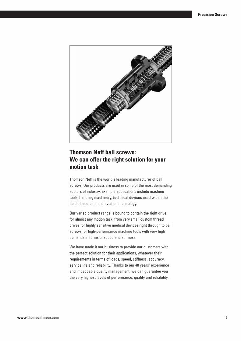
Thomson Neff ball screws: We can offer the right solution for your motion task
Thomson Neff is the world's leading manufacturer of ball screws . Our products are used in some of the most demanding sectors of industry . Example applications include machine tools, handling machinery, technical devices used within the field of medicine and aviation technology .
Our varied product range is bound to contain the right drive for almost any motion task: from very small custom thread drives for highly sensitive medical devices right through to ball screws for high-performance machine tools with very high demands in terms of speed and stiffness .
We have made it our business to provide our customers with the perfect solution for their applications, whatever their requirements in terms of loads, speed, stiffness, accuracy, service life and reliability . Thanks to our 40 years' experience and impeccable quality management, we can guarantee you the very highest levels of performance, quality and reliability .
Precision Screws
www.thomsonlinear.com6
Our ball screws are ideal for use in all technological and mechanical engineering applications . These mainly include:
– Machine tools
– Aircraft construction
– Wood working
– Handling equipment, industrial robots
– Printing and paper machines
– Traffic engineering
– Medical equipment
– Measuring technology
– …
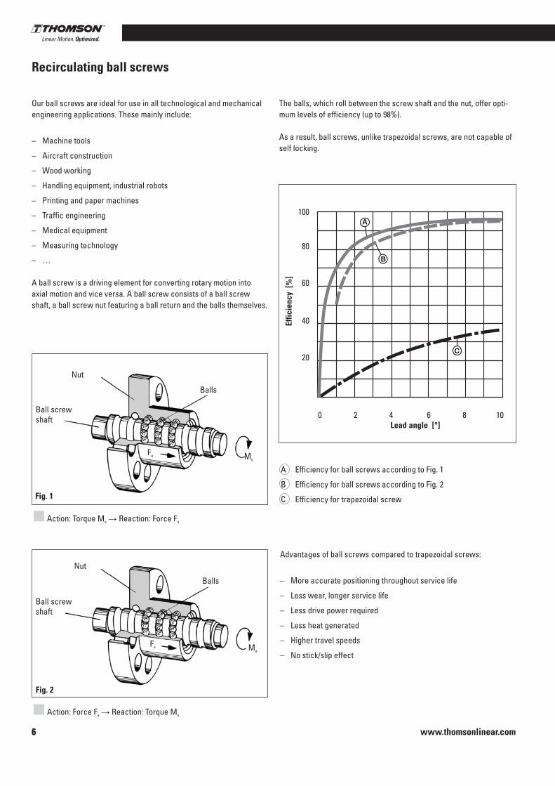
A ball screw is a driving element for converting rotary motion into axial motion and vice versa . A ball screw consists of a ball screw shaft, a ball screw nut featuring a ball return and the balls themselves .
The balls, which roll between the screw shaft and the nut, offer opti-mum levels of efficiency (up to 98%) .
As a result, ball screws, unlike trapezoidal screws, are not capable of self locking .
Effic
ienc
y [%
]
100
80
60
40
20
0 2 4 6 8 10Lead angle [°]
Fig. 1
Nut
Balls
Fa Me
Ball screw shaft
Fig. 2
Nut
Balls
Fe Ma
Action: Torque Me → Reaction: Force Fa
Action: Force Fe → Reaction: Torque Ma
A Efficiency for ball screws according to Fig . 1
B Efficiency for ball screws according to Fig . 2
C Efficiency for trapezoidal screw
Advantages of ball screws compared to trapezoidal screws:
– More accurate positioning throughout service life
– Less wear, longer service life
– Less drive power required
– Less heat generated
– Higher travel speeds
– No stick/slip effect
6
Recirculating ball screws
Ball screw shaft

www.thomsonlinear.com 7
Precision Screws
Reci
rcul
atin
g ba
ll sc
rew
s
7
General technical data for recirculating ball screws
Manufacturing processTHOMSON NEFF recirculating ball screws are manufactured in rol-led, ground and whirled versions . Both shaft and nut have a gothic arc profile . The load angle is 45° .
SpeedsThe permissible speed limit is currently 3000 rpm, up to 4500 rpm for spot measurements . This speed limit identifies the maximum speed that may only be used under optimum operating conditions .
Mounting positionThe mounting position of a lead screw may be selected freely . The only factor to be taken into consideration is that all radial forces generated must be absorbed by external guides .
PrecisionRolled Thomson Neff ball screw shafts are available in tolerance classes P3, P5, T5 and T7 .Ground/whirled Thomson Neff recirculating ball screws are availa-ble in tolerance classes up to P0 .
Self-lockingThanks to their low rolling friction, recirculating ball screws are not self-locking . It is therefore necessary to fit suitable motors with a holding brake, especially if the ball screw is mounted vertically .
TemperaturesAll ball screws are designed for ambient temperatures between -30°C and 80°C . Temperatures of no more than 110°C are also per-mitted for intermittent operations . Ball screws are only conditionally suited for temperatures below freezing .
Repetition accuracyThe repetition accuracy refers to the capability of a lead screw to return again to a set position it has previously traveled to under the same conditions . It corresponds to the mean position scatter range as defined in VDI/DGQ 3441 . Repetition accuracy is influenced by factors including:■ Load■ Speed■ Deceleration■ Direction of movement■ Temperature

www.thomsonlinear.com8
Precision drives us on
Our range complies with DIN 69051 and ISO 3408 . All nuts, both flanged and cylindrical nuts, are available with connections complying with DIN specifi-cations .
Every shaft can be supplied with customized end journals . On request, customers can also order screws with an annealed end for machining their own end journal .
Standard manufacturing program
Sizes used
Nominal diameter d0 [mm]
Nom
inal
lead
P h0
[mm
]
12 16 20 25 32 40 50 63 80 100 125 160
4
5
10
15
20
25
30
32
40
50
= rolled (stock item) = ground/whirled = heavy duty ground/whirled
www.thomsonlinear.com 9
Precision Screws
Reci
rcul
atin
g ba
ll sc
rew
s
Preloading methods
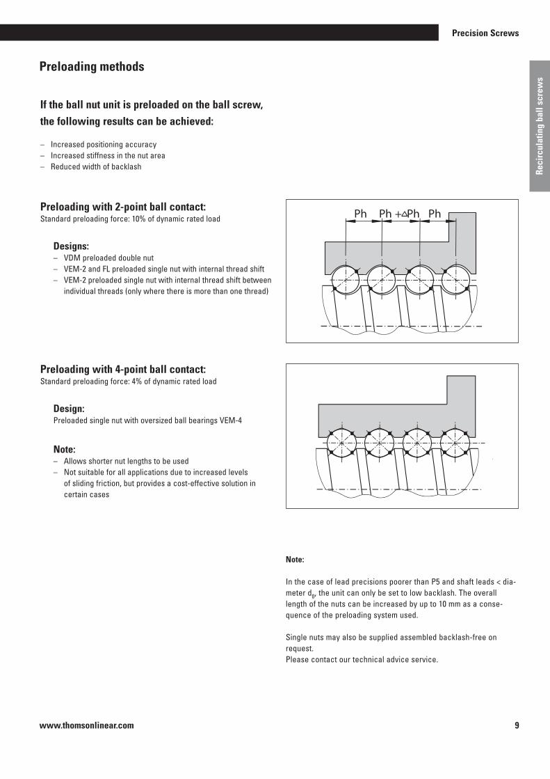
If the ball nut unit is preloaded on the ball screw, the following results can be achieved:
– Increased positioning accuracy– Increased stiffness in the nut area– Reduced width of backlash
Preloading with 2-point ball contact:Standard preloading force: 10% of dynamic rated load
Designs:– VDM preloaded double nut – VEM-2 and FL preloaded single nut with internal thread shift– VEM-2 preloaded single nut with internal thread shift between
individual threads (only where there is more than one thread)
Preloading with 4-point ball contact:Standard preloading force: 4% of dynamic rated load
Design:Preloaded single nut with oversized ball bearings VEM-4
Note:– Allows shorter nut lengths to be used– Not suitable for all applications due to increased levels
of sliding friction, but provides a cost-effective solution in certain cases
M*01
Note:
In the case of lead precisions poorer than P5 and shaft leads < dia-meter d0, the unit can only be set to low backlash . The overall length of the nuts can be increased by up to 10 mm as a conse-quence of the preloading system used .
Single nuts may also be supplied assembled backlash-free on request . Please contact our technical advice service .

www.thomsonlinear.com1010
Tolerance classes
Transport ball screwsPositioning ball screwsP TIndirect measuring system
Limit switch
Direct measuring system
Type and
tolerance class
P1
P3
P5
Permissible travel variance
within 300 mm travel in µm
6µm
12µm
23µm
52µm
Standard
Type and
tolerance class
T5
T7
Rotary encoder Linear measuring system
Stepper motor

www.thomsonlinear.com 11
Precision Screws
Reci
rcul
atin
g ba
ll sc
rew
s
THOMSON NEFF ball screw nuts are manufactured as flanged nuts and as cylindrical nuts . They can be combined with all shafts and the relevant end journals . Single nuts with backlash may also be supplied on an assembly sleeve .
Ball screw flanged nuts are manufactured with fixing holes, ball screw cylindrical nuts have a keyway or an external thread .
Ball screw nuts
THOMSON NEFF manufactures ball screw nuts with three different ball recirculation systems depending on the diameter and lead of the shafts used . Profiled wiper rings reduce the escape of lubricant and prevent the ingress of dirt .
THOMSON NEFF ball recirculation systems
Single return (EUS, MUS)For single-start ball screws
After each turn, the balls are lifted from the shaft raceway and set back by a single turn . THOMSON NEFF return systems made from glass-fiber rein-forced plastic or steel guarantee a faultless and gentle recirculation of the balls .May be supplied for short leads .
Internal return (channel, insert)For single-start and multiple-start ball screws.
After several turns, the balls are returned either by a patented plastic recir-culation system integrated into the nut or through recirculation channels also integrated into the nut using steel recirculation inserts .
External return (end cap)For multiple-start ball screws
The balls are recirculated via two special end caps and return channels integrated into the nut .
www.thomsonlinear.com12
Note:Backlash-free preloading is only possible with a lead accuracy ² 50 µm/300 mm and leads P < diameter d0 .Lead accuracies of > 50 µm/300 mm and leads ³ diameter d0 only allow a low backlash preloading . The total length of the nut can accelerate up to 10 mm due to the installed preloading disc .
Single nuts mounted backlash-free on request . Please contact our technical support .
Ball nut units – pre-loaded
As a rule all nuts can be combined to form backlash-free, pre-loaded nut unitsexcept when the lead is equal to or greater than the diameter of the screw .THOMSON NEFF supplies ready-to-install units with “O” pre-loading .
O pre-loading:With this type of pre-loading the lines of forces run in a rhomboidal pattern(O-shaped), i .e . the nuts are pressed apart by the pre-loading force . This configuration offers particularly high rigidity against tilting . The standard preloading is equal to 10 % of the dynamic load rating C .
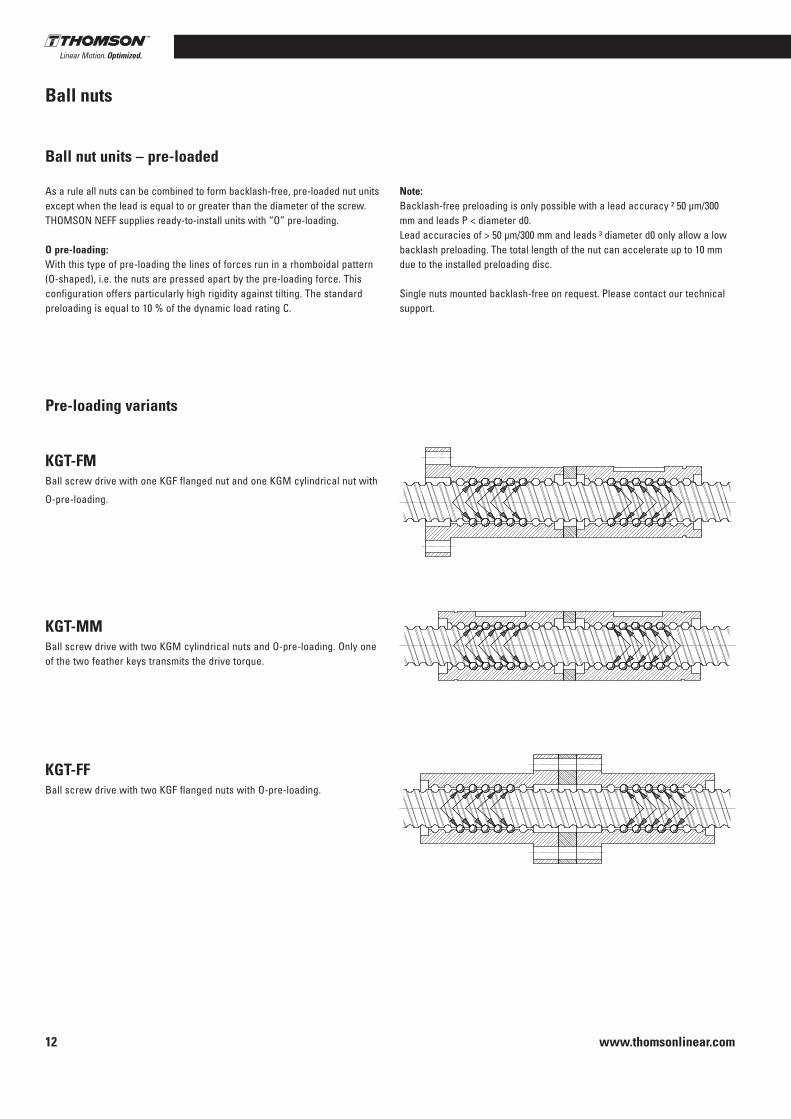
Pre-loading variants
KGT-FMBall screw drive with one KGF flanged nut and one KGM cylindrical nut with
O-pre-loading .
KGT-MMBall screw drive with two KGM cylindrical nuts and O-pre-loading . Only one of the two feather keys transmits the drive torque .
KGT-FFBall screw drive with two KGF flanged nuts with O-pre-loading .
Ball nuts

www.thomsonlinear.com 13
Precision Screws
Reci
rcul
atin
g ba
ll sc
rew
s
Method of manufacture
Thread rolling Rolled ball screw shafts are manufactured by cold forming without
chip removal . In this procedure, the bar stock is given a ball track in a continuous process . This means that it is, in principle, possible to create leads of any amount and to form any number of threads on the ball screw shaft . The shafts are then heat treated and polished . The forming process ensures high strength and a very good surface finish for the ball screw shafts .
Rolled ball screw shafts and the associated standard nuts can be supplied ex stock at favorable prices .
Special nuts to meet particular customer requirements are also possible .
Thomson Neff offers machined ends to the ball screw shafts, such as bearing seats, for instance, both to meet customer requirements and in accordance with common standard forms .
Tolerance classes
Rolled ball screw shafts are available in classes P3, P5, T5 and T7
Lengths
Various maximum shaft lengths are possible as a function of the nominal diameter:
■ Nominal diameter a 12 mm: Maximum shaft length 3000mm
■ Nominal diameter > 12 mm: Maximum shaft length 6000mm
Thomson Neff's rolled shafts have been setting the standard for many years:
■ Very low surface roughness thanks to the non-cutting rolling pro-cess and finishing polishing
■ Longest service lives thanks to optimized profiles and the maximum number of threads while simultaneously using large balls
■ Greatest quality and stable running thanks to patented ball circulation systems
■ Decades of experience in the manufacture of rolled and ground ball screws
Nuts A wide range of stock nut styles are available for you to use with
our rolled shafts .
■ FK, FH, KGF-D style flanged nuts with dimensions complying with DIN 69051
■ KGF-N style flanged nuts with a round flange and dimensions comp-lying with the Thomson Neff standard
■ Internally preloaded FL style flanged nuts with dimensions as speci-fied in DIN 69051
■ ZG style cylindrical nuts with external thread with dimensions com-plying with DIN 69051
■ KGM-D style cylindrical nuts with keyway with dimensions comp-lying with DIN 69051
■ KGM-N style cylindrical nuts with keyway with dimensions comp-lying with Thomson Neff standards
KGF-D style nuts can be combined with KGF-D or KGM-D style nuts to create preloaded nut units . The same is true for KGF-N style nuts which can be combined with KGF-N and KGM-N style nuts . Please contact our technical advisory service for further options with regards to preloaded nuts . On request, you may also have our nuts mounted backlash-free or with low backlash .
General information regarding rolled ball screws
www.thomsonlinear.com14
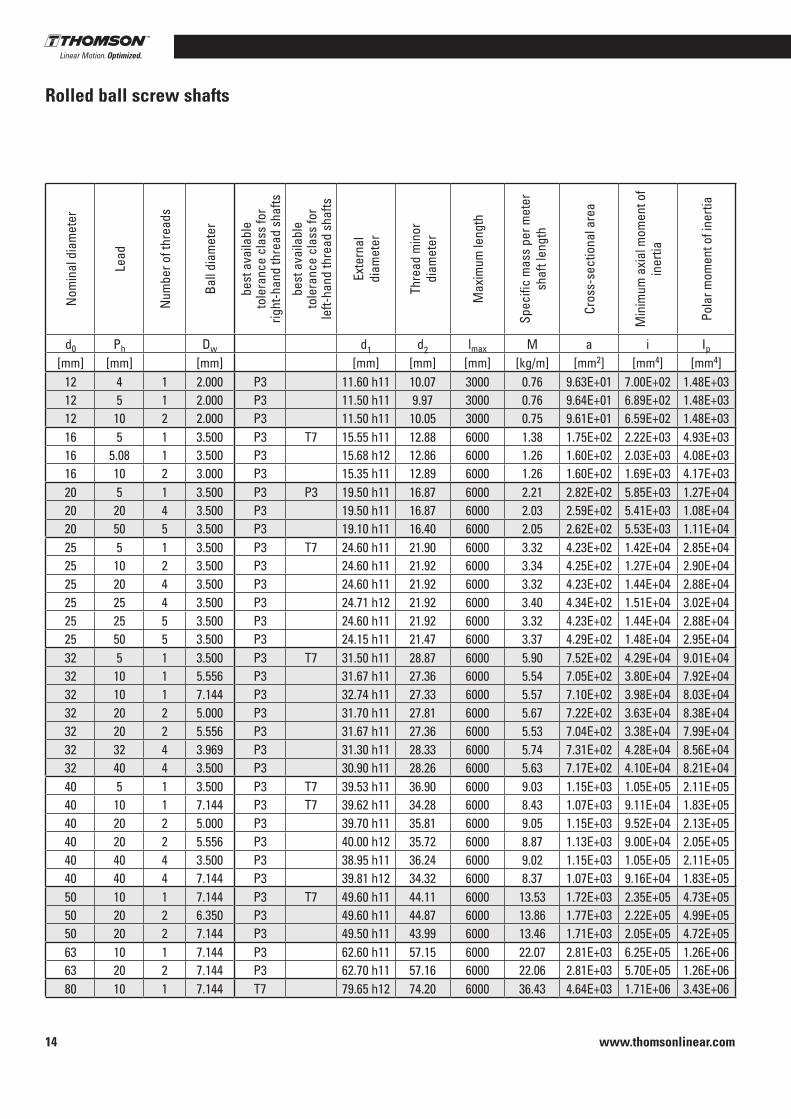
Rolled ball screw shaftsN
omin
al d
iam
eter
Lead
Num
ber o
f thr
eads
Ball
diam
eter
best
ava
ilabl
e
tole
ranc
e cl
ass
for
right
-han
d th
read
sha
fts
best
ava
ilabl
e
tole
ranc
e cl
ass
for
left-
hand
thre
ad s
hafts
Exte
rnal
diam
eter
Thre
ad m
inor
diam
eter
Max
imum
leng
th
Spec
ific
mas
s pe
r met
er
shaf
t len
gth
Cros
s-se
ctio
nal a
rea
Min
imum
axi
al m
omen
t of
iner
tia
Pola
r mom
ent o
f ine
rtia
Nut styles available from stock(R = with right-hand threadL = with left-hand thread)
d0 Ph Dw d1 d2 lmax M a i Ip KGF-D (FK)
KGF-D(FH)
KGF-L(FL)
KGM-G(ZG) KGF-D KGF-N KGM-D KGM-N FM-D FM-N MM-D MM-N FF-D FF-N
[mm] [mm] [mm] [mm] [mm] [mm] [kg/m] [mm2] [mm4] [mm4]12 4 1 2 .000 P3 11 .60 h11 10 .07 3000 0 .76 9 .63E+01 7 .00E+02 1 .48E+03 R R12 5 1 2 .000 P3 11 .50 h11 9 .97 3000 0 .76 9 .64E+01 6 .89E+02 1 .48E+03 R12 10 2 2 .000 P3 11 .50 h11 10 .05 3000 0 .75 9 .61E+01 6 .59E+02 1 .48E+03 R R16 5 1 3 .500 P3 T7 15 .55 h11 12 .88 6000 1 .38 1 .75E+02 2 .22E+03 4 .93E+03 R R R R R R R R R R R16 5 .08 1 3 .500 P3 15 .68 h12 12 .86 6000 1 .26 1 .60E+02 2 .03E+03 4 .08E+0316 10 2 3 .000 P3 15 .35 h11 12 .89 6000 1 .26 1 .60E+02 1 .69E+03 4 .17E+03 R R R R R20 5 1 3 .500 P3 P3 19 .50 h11 16 .87 6000 2 .21 2 .82E+02 5 .85E+03 1 .27E+04 R R R R+L R R+L R R+L R R+L R R+L R20 20 4 3 .500 P3 19 .50 h11 16 .87 6000 2 .03 2 .59E+02 5 .41E+03 1 .08E+04 R R R R R R20 50 5 3 .500 P3 19 .10 h11 16 .40 6000 2 .05 2 .62E+02 5 .53E+03 1 .11E+04 R R25 5 1 3 .500 P3 T7 24 .60 h11 21 .90 6000 3 .32 4 .23E+02 1 .42E+04 2 .85E+04 R R R R R R R R R R R R R25 10 2 3 .500 P3 24 .60 h11 21 .92 6000 3 .34 4 .25E+02 1 .27E+04 2 .90E+04 R R R R R R R25 20 4 3 .500 P3 24 .60 h11 21 .92 6000 3 .32 4 .23E+02 1 .44E+04 2 .88E+04 R R R R R25 25 4 3 .500 P3 24 .71 h12 21 .92 6000 3 .40 4 .34E+02 1 .51E+04 3 .02E+04 R25 25 5 3 .500 P3 24 .60 h11 21 .92 6000 3 .32 4 .23E+02 1 .44E+04 2 .88E+04 R R R R R25 50 5 3 .500 P3 24 .15 h11 21 .47 6000 3 .37 4 .29E+02 1 .48E+04 2 .95E+04 R R32 5 1 3 .500 P3 T7 31 .50 h11 28 .87 6000 5 .90 7 .52E+02 4 .29E+04 9 .01E+04 R R R R R R R R R R R R R32 10 1 5 .556 P3 31 .67 h11 27 .36 6000 5 .54 7 .05E+02 3 .80E+04 7 .92E+04 R R R32 10 1 7 .144 P3 32 .74 h11 27 .33 6000 5 .57 7 .10E+02 3 .98E+04 8 .03E+04 R R R R R R R R32 20 2 5 .000 P3 31 .70 h11 27 .81 6000 5 .67 7 .22E+02 3 .63E+04 8 .38E+04 R R R R R32 20 2 5 .556 P3 31 .67 h11 27 .36 6000 5 .53 7 .04E+02 3 .38E+04 7 .99E+04 R32 32 4 3 .969 P3 31 .30 h11 28 .33 6000 5 .74 7 .31E+02 4 .28E+04 8 .56E+04 R R R32 40 4 3 .500 P3 30 .90 h11 28 .26 6000 5 .63 7 .17E+02 4 .10E+04 8 .21E+04 R R40 5 1 3 .500 P3 T7 39 .53 h11 36 .90 6000 9 .03 1 .15E+03 1 .05E+05 2 .11E+05 R R R R R R R R R R R R R40 10 1 7 .144 P3 T7 39 .62 h11 34 .28 6000 8 .43 1 .07E+03 9 .11E+04 1 .83E+05 R R R R R R R R R R R40 20 2 5 .000 P3 39 .70 h11 35 .81 6000 9 .05 1 .15E+03 9 .52E+04 2 .13E+05 R R40 20 2 5 .556 P3 40 .00 h12 35 .72 6000 8 .87 1 .13E+03 9 .00E+04 2 .05E+05 R R R R R40 40 4 3 .500 P3 38 .95 h11 36 .24 6000 9 .02 1 .15E+03 1 .05E+05 2 .11E+05 R40 40 4 7 .144 P3 39 .81 h12 34 .32 6000 8 .37 1 .07E+03 9 .16E+04 1 .83E+05 R R R R R R R R R R R R R50 10 1 7 .144 P3 T7 49 .60 h11 44 .11 6000 13 .53 1 .72E+03 2 .35E+05 4 .73E+05 R50 20 2 6 .350 P3 49 .60 h11 44 .87 6000 13 .86 1 .77E+03 2 .22E+05 4 .99E+05 R R R R R50 20 2 7 .144 P3 49 .50 h11 43 .99 6000 13 .46 1 .71E+03 2 .05E+05 4 .72E+05 R R R R R R R R R R R R R63 10 1 7 .144 P3 62 .60 h11 57 .15 6000 22 .07 2 .81E+03 6 .25E+05 1 .26E+06 R R R R R R63 20 2 7 .144 P3 62 .70 h11 57 .16 6000 22 .06 2 .81E+03 5 .70E+05 1 .26E+06 R R R R R R R80 10 1 7 .144 T7 79 .65 h12 74 .20 6000 36 .43 4 .64E+03 1 .71E+06 3 .43E+06 R R R R

www.thomsonlinear.com 15
Precision Screws
Reci
rcul
atin
g ba
ll sc
rew
s
Nom
inal
dia
met
er
Lead
Num
ber o
f thr
eads
Ball
diam
eter
best
ava
ilabl
e
tole
ranc
e cl
ass
for
right
-han
d th
read
sha
fts
best
ava
ilabl
e
tole
ranc
e cl
ass
for
left-
hand
thre
ad s
hafts
Exte
rnal
diam
eter
Thre
ad m
inor
diam
eter
Max
imum
leng
th
Spec
ific
mas
s pe
r met
er
shaf
t len
gth
Cros
s-se
ctio
nal a
rea
Min
imum
axi
al m
omen
t of
iner
tia
Pola
r mom
ent o
f ine
rtia
Nut styles available from stock(R = with right-hand threadL = with left-hand thread)
d0 Ph Dw d1 d2 lmax M a i Ip KGF-D (FK)
KGF-D(FH)
KGF-L(FL)
KGM-G(ZG) KGF-D KGF-N KGM-D KGM-N FM-D FM-N MM-D MM-N FF-D FF-N
[mm] [mm] [mm] [mm] [mm] [mm] [kg/m] [mm2] [mm4] [mm4]12 4 1 2 .000 P3 11 .60 h11 10 .07 3000 0 .76 9 .63E+01 7 .00E+02 1 .48E+03 R R12 5 1 2 .000 P3 11 .50 h11 9 .97 3000 0 .76 9 .64E+01 6 .89E+02 1 .48E+03 R12 10 2 2 .000 P3 11 .50 h11 10 .05 3000 0 .75 9 .61E+01 6 .59E+02 1 .48E+03 R R16 5 1 3 .500 P3 T7 15 .55 h11 12 .88 6000 1 .38 1 .75E+02 2 .22E+03 4 .93E+03 R R R R R R R R R R R16 5 .08 1 3 .500 P3 15 .68 h12 12 .86 6000 1 .26 1 .60E+02 2 .03E+03 4 .08E+0316 10 2 3 .000 P3 15 .35 h11 12 .89 6000 1 .26 1 .60E+02 1 .69E+03 4 .17E+03 R R R R R20 5 1 3 .500 P3 P3 19 .50 h11 16 .87 6000 2 .21 2 .82E+02 5 .85E+03 1 .27E+04 R R R R+L R R+L R R+L R R+L R R+L R20 20 4 3 .500 P3 19 .50 h11 16 .87 6000 2 .03 2 .59E+02 5 .41E+03 1 .08E+04 R R R R R R20 50 5 3 .500 P3 19 .10 h11 16 .40 6000 2 .05 2 .62E+02 5 .53E+03 1 .11E+04 R R25 5 1 3 .500 P3 T7 24 .60 h11 21 .90 6000 3 .32 4 .23E+02 1 .42E+04 2 .85E+04 R R R R R R R R R R R R R25 10 2 3 .500 P3 24 .60 h11 21 .92 6000 3 .34 4 .25E+02 1 .27E+04 2 .90E+04 R R R R R R R25 20 4 3 .500 P3 24 .60 h11 21 .92 6000 3 .32 4 .23E+02 1 .44E+04 2 .88E+04 R R R R R25 25 4 3 .500 P3 24 .71 h12 21 .92 6000 3 .40 4 .34E+02 1 .51E+04 3 .02E+04 R25 25 5 3 .500 P3 24 .60 h11 21 .92 6000 3 .32 4 .23E+02 1 .44E+04 2 .88E+04 R R R R R25 50 5 3 .500 P3 24 .15 h11 21 .47 6000 3 .37 4 .29E+02 1 .48E+04 2 .95E+04 R R32 5 1 3 .500 P3 T7 31 .50 h11 28 .87 6000 5 .90 7 .52E+02 4 .29E+04 9 .01E+04 R R R R R R R R R R R R R32 10 1 5 .556 P3 31 .67 h11 27 .36 6000 5 .54 7 .05E+02 3 .80E+04 7 .92E+04 R R R32 10 1 7 .144 P3 32 .74 h11 27 .33 6000 5 .57 7 .10E+02 3 .98E+04 8 .03E+04 R R R R R R R R32 20 2 5 .000 P3 31 .70 h11 27 .81 6000 5 .67 7 .22E+02 3 .63E+04 8 .38E+04 R R R R R32 20 2 5 .556 P3 31 .67 h11 27 .36 6000 5 .53 7 .04E+02 3 .38E+04 7 .99E+04 R32 32 4 3 .969 P3 31 .30 h11 28 .33 6000 5 .74 7 .31E+02 4 .28E+04 8 .56E+04 R R R32 40 4 3 .500 P3 30 .90 h11 28 .26 6000 5 .63 7 .17E+02 4 .10E+04 8 .21E+04 R R40 5 1 3 .500 P3 T7 39 .53 h11 36 .90 6000 9 .03 1 .15E+03 1 .05E+05 2 .11E+05 R R R R R R R R R R R R R40 10 1 7 .144 P3 T7 39 .62 h11 34 .28 6000 8 .43 1 .07E+03 9 .11E+04 1 .83E+05 R R R R R R R R R R R40 20 2 5 .000 P3 39 .70 h11 35 .81 6000 9 .05 1 .15E+03 9 .52E+04 2 .13E+05 R R40 20 2 5 .556 P3 40 .00 h12 35 .72 6000 8 .87 1 .13E+03 9 .00E+04 2 .05E+05 R R R R R40 40 4 3 .500 P3 38 .95 h11 36 .24 6000 9 .02 1 .15E+03 1 .05E+05 2 .11E+05 R40 40 4 7 .144 P3 39 .81 h12 34 .32 6000 8 .37 1 .07E+03 9 .16E+04 1 .83E+05 R R R R R R R R R R R R R50 10 1 7 .144 P3 T7 49 .60 h11 44 .11 6000 13 .53 1 .72E+03 2 .35E+05 4 .73E+05 R50 20 2 6 .350 P3 49 .60 h11 44 .87 6000 13 .86 1 .77E+03 2 .22E+05 4 .99E+05 R R R R R50 20 2 7 .144 P3 49 .50 h11 43 .99 6000 13 .46 1 .71E+03 2 .05E+05 4 .72E+05 R R R R R R R R R R R R R63 10 1 7 .144 P3 62 .60 h11 57 .15 6000 22 .07 2 .81E+03 6 .25E+05 1 .26E+06 R R R R R R63 20 2 7 .144 P3 62 .70 h11 57 .16 6000 22 .06 2 .81E+03 5 .70E+05 1 .26E+06 R R R R R R R80 10 1 7 .144 T7 79 .65 h12 74 .20 6000 36 .43 4 .64E+03 1 .71E+06 3 .43E+06 R R R R
KGF-D (FK)
KGF-D (FH)
KGF-L (FL)
KGM-G (ZG)
KGF-D
KGF-N
KGM-D
KGM-N
www.thomsonlinear.com16
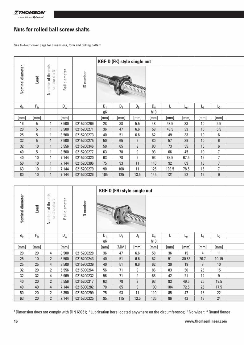
Nuts for rolled ball screw shafts
1 Dimension does not comply with DIN 69051; 2 Lubrication bore located anywhere on the circumference; 3 No wiper; 4 Round flange
See fold-out cover page for dimensions, form and drilling pattern
Nom
inal
dia
met
er
Lead
Num
ber o
f thr
eads
on
the
shaf
t
Ball
diam
eter
ID n
umbe
r
KGF-D (FK) style single nut
Nut
form
Drill
ing
patte
rn
Retu
rn s
yste
m
Nom
inal
ax
ial b
ackl
ash
Num
ber o
f loa
ded
turn
s
Mod
ified
dyn
amic
ra
ted
load
Mod
ified
st
atic
rate
d lo
ad
d0 Ph Dw D1 D4 D5 D6 L Lm L1 L3 L7 L8 DB LB L10 Cam C0am
g6 h13 h13 h13[mm] [mm] [mm] [mm] [mm] [mm] [mm] [mm] [mm] [mm] [mm] [mm] [mm] [mm] [mm] [mm] [mm] [kN] [kN]
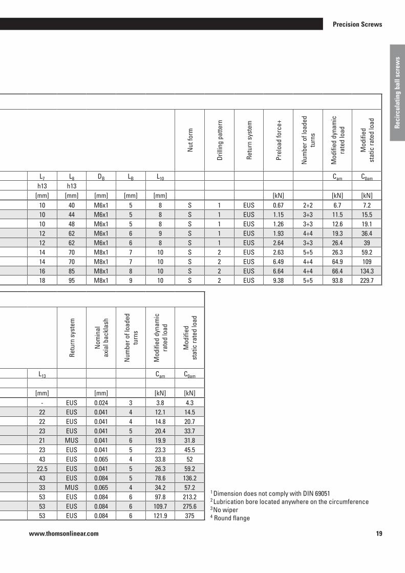
16 5 1 3 .500 0215200269 28 38 5 .5 48 48 .5 33 10 5 .5 10 40 M6x1 5 8 S 1 EUS 0 .041 3 9 .5 10 .920 5 1 3 .500 0215200271 36 47 6 .6 58 48 .5 33 10 5 .5 10 44 M6x1 5 8 S 1 EUS 0 .041 3 11 .5 15 .525 5 1 3 .500 0215200273 40 51 6 .6 62 49 33 10 6 10 48 M6x1 5 8 S 1 EUS 0 .041 3 13 .1 20 .232 5 1 3 .500 0215200275 50 65 9 80 57 39 10 6 12 62 M6x1 6 8 S 1 EUS 0 .041 4 19 .3 36 .332 10 1 5 .556 0215200346 50 65 9 80 73 55 16 6 12 62 M6x1 6 8 S 1 EUS 0 .065 3 26 .4 3940 5 1 3 .500 0215200277 63 78 9 93 66 45 10 7 14 70 M8x1 7 10 S 2 EUS 0 .041 5 26 .3 59 .240 10 1 7 .144 0215200320 63 78 9 93 88 .5 67 .5 16 7 14 70 M8x1 7 10 S 2 EUS 0 .084 4 64 .9 10950 10 1 7 .144 0215200306 75 93 11 110 92 69 13 7 16 85 M8x1 8 9 S 2 EUS 0 .084 4 66 .4 134 .363 10 1 7 .144 0215200279 90 108 11 125 103 .5 78 .5 16 7 18 95 M8x1 9 10 S 2 EUS 0 .084 5 93 .8 229 .780 10 1 7 .144 0215200326 105 125 13 .5 145 121 92 16 9 20 110 M8x1 10 10 S 2 EUS 0 .084 6 121 .9 374 .9
Nom
inal
dia
met
er
Lead
Num
ber o
f thr
eads
on
the
shaf
t
Ball
diam
eter
ID n
umbe
r
KGF-D (FH) style single nut
Nut
form
Drill
ing
patte
rn
Retu
rn s
yste
m
Nom
inal
ax
ial b
ackl
ash
Num
ber o
f loa
ded
turn
s
Mod
ified
dyn
amic
ra
ted
load
Mod
ified
st
atic
rate
d lo
ad
d0 Ph Dw D1 D4 D5 D6 L Lm L1 L3 L7 L8 DB LB L10 Cam C0am
g6 h13 h13 h13[mm] [mm] [mm] [mm] [MM] [mm] [mm] [mm] [mm] [mm] [mm] [mm] [mm] [mm] [mm] [mm] [mm] [kN] [kN]
20 20 4 3 .500 0215200228 36 47 6 .6 58 36 15 4 11 10 44 M6x1 5 8 S 1 End cap 0 .041 2 .8 10 .8 17 .525 10 2 3 .500 0215200243 40 51 6 .6 62 51 30 .85 20 .7 10 .15 10 48 M6x1 5 8 S 1 End cap 0 .041 6 .1 24 .7 53 .425 25 4 3 .500 0215900239 40 51 6 .6 62 39 19 9 10 10 48 M6x1 5 8 S 1 End cap 0 .041 3 .6 13 .1 26 .032 20 2 5 .556 0215900264 56 71 9 86 83 56 25 15 12 65 M6x1 6 9 S 1 End cap 0 .065 5 .6 47 .2 83 .232 32 4 3 .969 0215200232 56 71 9 86 42 21 12 9 12 68 M6x1 6 8 S 1 End cap 0 .047 4 19 .7 3940 20 2 5 .556 0215200317 63 78 9 93 83 49 .5 25 19 .5 14 70 M8x1 7 10 S 2 End cap 0 .065 5 .6 52 .2 103 .640 40 4 7 .144 0215900282 70 85 9 100 104 72 .5 25 17 .5 14 75 M8x1 7 10 S 2 End cap 0 .084 6 .4 80 .0 178 .650 20 2 6 .350 0215200299 75 93 11 110 85 47 16 22 16 85 M8x1 8 10 S 2 End cap 0 .084 5 .6 78 .8 188 .763 20 2 7 .144 0215200325 95 115 13 .5 135 86 42 18 24 20 100 M8x1 10 10 S 2 End cap 0 .084 5 .6 103 .1 270 .8

www.thomsonlinear.com 17
Precision Screws
Reci
rcul
atin
g ba
ll sc
rew
s
Nom
inal
dia
met
er
Lead
Num
ber o
f thr
eads
on
the
shaf
t
Ball
diam
eter
ID n
umbe
r
KGF-D (FK) style single nut
Nut
form
Drill
ing
patte
rn
Retu
rn s
yste
m
Nom
inal
ax
ial b
ackl
ash
Num
ber o
f loa
ded
turn
s
Mod
ified
dyn
amic
ra
ted
load
Mod
ified
st
atic
rate
d lo
ad
d0 Ph Dw D1 D4 D5 D6 L Lm L1 L3 L7 L8 DB LB L10 Cam C0am
g6 h13 h13 h13[mm] [mm] [mm] [mm] [mm] [mm] [mm] [mm] [mm] [mm] [mm] [mm] [mm] [mm] [mm] [mm] [mm] [kN] [kN]
16 5 1 3 .500 0215200269 28 38 5 .5 48 48 .5 33 10 5 .5 10 40 M6x1 5 8 S 1 EUS 0 .041 3 9 .5 10 .920 5 1 3 .500 0215200271 36 47 6 .6 58 48 .5 33 10 5 .5 10 44 M6x1 5 8 S 1 EUS 0 .041 3 11 .5 15 .525 5 1 3 .500 0215200273 40 51 6 .6 62 49 33 10 6 10 48 M6x1 5 8 S 1 EUS 0 .041 3 13 .1 20 .232 5 1 3 .500 0215200275 50 65 9 80 57 39 10 6 12 62 M6x1 6 8 S 1 EUS 0 .041 4 19 .3 36 .332 10 1 5 .556 0215200346 50 65 9 80 73 55 16 6 12 62 M6x1 6 8 S 1 EUS 0 .065 3 26 .4 3940 5 1 3 .500 0215200277 63 78 9 93 66 45 10 7 14 70 M8x1 7 10 S 2 EUS 0 .041 5 26 .3 59 .240 10 1 7 .144 0215200320 63 78 9 93 88 .5 67 .5 16 7 14 70 M8x1 7 10 S 2 EUS 0 .084 4 64 .9 10950 10 1 7 .144 0215200306 75 93 11 110 92 69 13 7 16 85 M8x1 8 9 S 2 EUS 0 .084 4 66 .4 134 .363 10 1 7 .144 0215200279 90 108 11 125 103 .5 78 .5 16 7 18 95 M8x1 9 10 S 2 EUS 0 .084 5 93 .8 229 .780 10 1 7 .144 0215200326 105 125 13 .5 145 121 92 16 9 20 110 M8x1 10 10 S 2 EUS 0 .084 6 121 .9 374 .9
Nom
inal
dia
met
er
Lead
Num
ber o
f thr
eads
on
the
shaf
t
Ball
diam
eter
ID n
umbe
r
KGF-D (FH) style single nut
Nut
form
Drill
ing
patte
rn
Retu
rn s
yste
m
Nom
inal
ax
ial b
ackl
ash
Num
ber o
f loa
ded
turn
s
Mod
ified
dyn
amic
ra
ted
load
Mod
ified
st
atic
rate
d lo
ad
d0 Ph Dw D1 D4 D5 D6 L Lm L1 L3 L7 L8 DB LB L10 Cam C0am
g6 h13 h13 h13[mm] [mm] [mm] [mm] [MM] [mm] [mm] [mm] [mm] [mm] [mm] [mm] [mm] [mm] [mm] [mm] [mm] [kN] [kN]
20 20 4 3 .500 0215200228 36 47 6 .6 58 36 15 4 11 10 44 M6x1 5 8 S 1 End cap 0 .041 2 .8 10 .8 17 .525 10 2 3 .500 0215200243 40 51 6 .6 62 51 30 .85 20 .7 10 .15 10 48 M6x1 5 8 S 1 End cap 0 .041 6 .1 24 .7 53 .425 25 4 3 .500 0215900239 40 51 6 .6 62 39 19 9 10 10 48 M6x1 5 8 S 1 End cap 0 .041 3 .6 13 .1 26 .032 20 2 5 .556 0215900264 56 71 9 86 83 56 25 15 12 65 M6x1 6 9 S 1 End cap 0 .065 5 .6 47 .2 83 .232 32 4 3 .969 0215200232 56 71 9 86 42 21 12 9 12 68 M6x1 6 8 S 1 End cap 0 .047 4 19 .7 3940 20 2 5 .556 0215200317 63 78 9 93 83 49 .5 25 19 .5 14 70 M8x1 7 10 S 2 End cap 0 .065 5 .6 52 .2 103 .640 40 4 7 .144 0215900282 70 85 9 100 104 72 .5 25 17 .5 14 75 M8x1 7 10 S 2 End cap 0 .084 6 .4 80 .0 178 .650 20 2 6 .350 0215200299 75 93 11 110 85 47 16 22 16 85 M8x1 8 10 S 2 End cap 0 .084 5 .6 78 .8 188 .763 20 2 7 .144 0215200325 95 115 13 .5 135 86 42 18 24 20 100 M8x1 10 10 S 2 End cap 0 .084 5 .6 103 .1 270 .8
www.thomsonlinear.com18
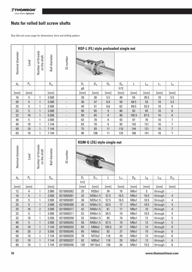
Nuts for rolled ball screw shafts
See fold-out cover page for dimensions, form and drilling pattern
Nom
inal
dia
met
er
Lead
Num
ber o
f thr
eads
on
the
shaf
t
Ball
diam
eter
ID n
umbe
r
KGF-L (FL) style preloaded single nut
Nut
form
Drill
ing
patte
rn
Retu
rn s
yste
m
Prel
oad
forc
e+
Num
ber o
f loa
ded
turn
s
Mod
ified
dyn
amic
ra
ted
load
Mod
ified
st
atic
rate
d lo
ad
d0 Ph Dw D1 D4 D5 D6 L Lm L1 L3 L7 L8 DB LB L10 Cam C0am
g6 h13 h13 h13[mm] [mm] [mm] [mm] [mm] [mm] [mm] [mm] [mm] [mm] [mm] [mm] [mm] [mm] [mm] [mm] [kN] [kN] [kN]
16 5 1 3 .500 - 28 38 5 .5 48 55 39 .5 10 5 .5 10 40 M6x1 5 8 S 1 EUS 0 .67 2+2 6 .7 7 .220 5 1 3 .500 - 36 47 6 .6 58 68 .5 53 10 5 .5 10 44 M6x1 5 8 S 1 EUS 1 .15 3+3 11 .5 15 .525 5 1 3 .500 - 40 51 6 .6 62 69 .5 53 .5 10 6 10 48 M6x1 5 8 S 1 EUS 1 .26 3+3 12 .6 19 .132 5 1 3 .500 - 50 65 9 80 83 65 10 6 12 62 M6x1 6 9 S 1 EUS 1 .93 4+4 19 .3 36 .432 10 1 5 .556 - 50 65 9 80 105 .5 87 .5 16 6 12 62 M6x1 6 8 S 1 EUS 2 .64 3+3 26 .4 3940 5 1 3 .500 - 63 78 9 93 97 76 10 7 14 70 M8x1 7 10 S 2 EUS 2 .63 5+5 26 .3 59 .240 10 1 7 .144 - 63 78 9 93 142 121 16 7 14 70 M8x1 7 10 S 2 EUS 6 .49 4+4 64 .9 10950 10 1 7 .144 - 75 93 11 110 144 121 16 7 16 85 M8x1 8 10 S 2 EUS 6 .64 4+4 66 .4 134 .363 10 1 7 .144 - 90 108 11 125 166 141 16 7 18 95 M8x1 9 10 S 2 EUS 9 .38 5+5 93 .8 229 .7
Nom
inal
dia
met
er
Lead
Num
ber o
f thr
eads
on
the
shaf
t
Ball
diam
eter
ID n
umbe
r
KGM-G (ZG) style single nut
Retu
rn s
yste
m
Nom
inal
ax
ial b
ackl
ash
Num
ber o
f loa
ded
turn
s
Mod
ified
dyn
amic
ra
ted
load
Mod
ified
st
atic
rate
d lo
ad
d0 Ph Dw D1 D11 L L11 DB LB L10 D13 L13 Cam C0am
h12[mm] [mm] [mm] [mm] [mm] [mm] [mm] [mm] [mm] [mm] [mm] [mm] [mm] [kN] [kN]
12 4 1 2 .000 0215050362 25 M20x1 34 10 M6x1 5 through - - EUS 0 .024 3 3 .8 4 .316 5 1 3 .500 0215050301 32 M30x1 .5 57 .5 16 .5 M6x1 10 .5 through 4 22 EUS 0 .041 4 12 .1 14 .520 5 1 3 .500 0215050307 38 M35x1 .5 57 .5 16 .5 M6x1 10 .5 through 4 22 EUS 0 .041 4 14 .8 20 .725 5 1 3 .500 0215050309 42 M40x1 .5 63 .5 17 M6x1 10 .5 through 4 23 EUS 0 .041 5 20 .4 33 .725 10 2 3 .500 0215050317 42 M40x1 .5 61 17 M6x1 10 through 4 21 MUS 0 .041 6 19 .9 31 .832 5 1 3 .500 0215050311 52 M48x1 .5 65 .5 19 M6x1 10 .5 through 5 23 EUS 0 .041 5 23 .3 45 .532 10 1 5 .556 0215050358 52 M48x1 .5 85 19 M6x1 12 through 5 43 EUS 0 .065 4 33 .8 5240 5 1 3 .500 0215050342 58 M56x1 .5 67 .5 19 M8x1 12 through 5 22 .5 EUS 0 .041 5 26 .3 59 .240 10 1 7 .144 0215050333 65 M60x2 105 .5 27 M8x1 13 through 6 43 EUS 0 .084 5 78 .6 136 .240 20 2 5 .556 0215050345 65 M60x2 83 27 M6x1 10 through 6 33 MUS 0 .065 4 34 .2 57 .250 10 1 7 .144 0215050335 78 M72x2 118 29 M8x1 13 through 6 53 EUS 0 .084 6 97 .8 213 .263 10 1 7 .144 0215050337 92 M85x2 118 29 M8x1 13 through 6 53 EUS 0 .084 6 109 .7 275 .680 10 1 7 .144 0215050346 120 M110x2 126 34 M8x1 15 .5 through 8 53 EUS 0 .084 6 121 .9 375
www.thomsonlinear.com 19
Precision Screws
Reci
rcul
atin
g ba
ll sc
rew
s
1 Dimension does not comply with DIN 69051 2 Lubrication bore located anywhere on the circumference 3 No wiper 4 Round flange
Nom
inal
dia
met
er
Lead
Num
ber o
f thr
eads
on
the
shaf
t
Ball
diam
eter
ID n
umbe
r
KGF-L (FL) style preloaded single nut
Nut
form
Drill
ing
patte
rn
Retu
rn s
yste
m
Prel
oad
forc
e+
Num
ber o
f loa
ded
turn
s
Mod
ified
dyn
amic
ra
ted
load
Mod
ified
st
atic
rate
d lo
ad
d0 Ph Dw D1 D4 D5 D6 L Lm L1 L3 L7 L8 DB LB L10 Cam C0am
g6 h13 h13 h13[mm] [mm] [mm] [mm] [mm] [mm] [mm] [mm] [mm] [mm] [mm] [mm] [mm] [mm] [mm] [mm] [kN] [kN] [kN]
16 5 1 3 .500 - 28 38 5 .5 48 55 39 .5 10 5 .5 10 40 M6x1 5 8 S 1 EUS 0 .67 2+2 6 .7 7 .220 5 1 3 .500 - 36 47 6 .6 58 68 .5 53 10 5 .5 10 44 M6x1 5 8 S 1 EUS 1 .15 3+3 11 .5 15 .525 5 1 3 .500 - 40 51 6 .6 62 69 .5 53 .5 10 6 10 48 M6x1 5 8 S 1 EUS 1 .26 3+3 12 .6 19 .132 5 1 3 .500 - 50 65 9 80 83 65 10 6 12 62 M6x1 6 9 S 1 EUS 1 .93 4+4 19 .3 36 .432 10 1 5 .556 - 50 65 9 80 105 .5 87 .5 16 6 12 62 M6x1 6 8 S 1 EUS 2 .64 3+3 26 .4 3940 5 1 3 .500 - 63 78 9 93 97 76 10 7 14 70 M8x1 7 10 S 2 EUS 2 .63 5+5 26 .3 59 .240 10 1 7 .144 - 63 78 9 93 142 121 16 7 14 70 M8x1 7 10 S 2 EUS 6 .49 4+4 64 .9 10950 10 1 7 .144 - 75 93 11 110 144 121 16 7 16 85 M8x1 8 10 S 2 EUS 6 .64 4+4 66 .4 134 .363 10 1 7 .144 - 90 108 11 125 166 141 16 7 18 95 M8x1 9 10 S 2 EUS 9 .38 5+5 93 .8 229 .7
Nom
inal
dia
met
er
Lead
Num
ber o
f thr
eads
on
the
shaf
t
Ball
diam
eter
ID n
umbe
r
KGM-G (ZG) style single nut
Retu
rn s
yste
m
Nom
inal
ax
ial b
ackl
ash
Num
ber o
f loa
ded
turn
s
Mod
ified
dyn
amic
ra
ted
load
Mod
ified
st
atic
rate
d lo
ad
d0 Ph Dw D1 D11 L L11 DB LB L10 D13 L13 Cam C0am
h12[mm] [mm] [mm] [mm] [mm] [mm] [mm] [mm] [mm] [mm] [mm] [mm] [mm] [kN] [kN]
12 4 1 2 .000 0215050362 25 M20x1 34 10 M6x1 5 through - - EUS 0 .024 3 3 .8 4 .316 5 1 3 .500 0215050301 32 M30x1 .5 57 .5 16 .5 M6x1 10 .5 through 4 22 EUS 0 .041 4 12 .1 14 .520 5 1 3 .500 0215050307 38 M35x1 .5 57 .5 16 .5 M6x1 10 .5 through 4 22 EUS 0 .041 4 14 .8 20 .725 5 1 3 .500 0215050309 42 M40x1 .5 63 .5 17 M6x1 10 .5 through 4 23 EUS 0 .041 5 20 .4 33 .725 10 2 3 .500 0215050317 42 M40x1 .5 61 17 M6x1 10 through 4 21 MUS 0 .041 6 19 .9 31 .832 5 1 3 .500 0215050311 52 M48x1 .5 65 .5 19 M6x1 10 .5 through 5 23 EUS 0 .041 5 23 .3 45 .532 10 1 5 .556 0215050358 52 M48x1 .5 85 19 M6x1 12 through 5 43 EUS 0 .065 4 33 .8 5240 5 1 3 .500 0215050342 58 M56x1 .5 67 .5 19 M8x1 12 through 5 22 .5 EUS 0 .041 5 26 .3 59 .240 10 1 7 .144 0215050333 65 M60x2 105 .5 27 M8x1 13 through 6 43 EUS 0 .084 5 78 .6 136 .240 20 2 5 .556 0215050345 65 M60x2 83 27 M6x1 10 through 6 33 MUS 0 .065 4 34 .2 57 .250 10 1 7 .144 0215050335 78 M72x2 118 29 M8x1 13 through 6 53 EUS 0 .084 6 97 .8 213 .263 10 1 7 .144 0215050337 92 M85x2 118 29 M8x1 13 through 6 53 EUS 0 .084 6 109 .7 275 .680 10 1 7 .144 0215050346 120 M110x2 126 34 M8x1 15 .5 through 8 53 EUS 0 .084 6 121 .9 375

www.thomsonlinear.com20
1 Dimension does not comply with DIN 69051; 2 Lubrication bore located anywhere on the circumference; 3 No wiper; 4 Round flange
Nuts for rolled ball screw shafts
See fold-out cover page for dimensions, form and drilling pattern
Nom
inal
dia
met
er
Lead
Num
ber o
f thr
eads
on
the
shaf
t
Ball
diam
eter
ID n
umbe
r
KGF-D style single nut
Nut
form
Drill
ing
patte
rn
Retu
rn s
yste
m
Nom
inal
ax
ial b
ackl
ash
Num
ber o
f loa
ded
turn
s
Mod
ified
dyn
amic
ra
ted
load
Mod
ified
st
atic
rate
d lo
ad
d0 Ph Dw D1 D4 D5 D6 L Lm L1 L3 L7 L8 DB LB L10 Cam C0am
g6 h13 h13 h13[mm] [mm] [mm] [mm] [mm] [mm] [mm] [mm] [mm] [mm] [mm] [mm] [mm] [mm] [mm] [mm] [mm] [kN] [kN]
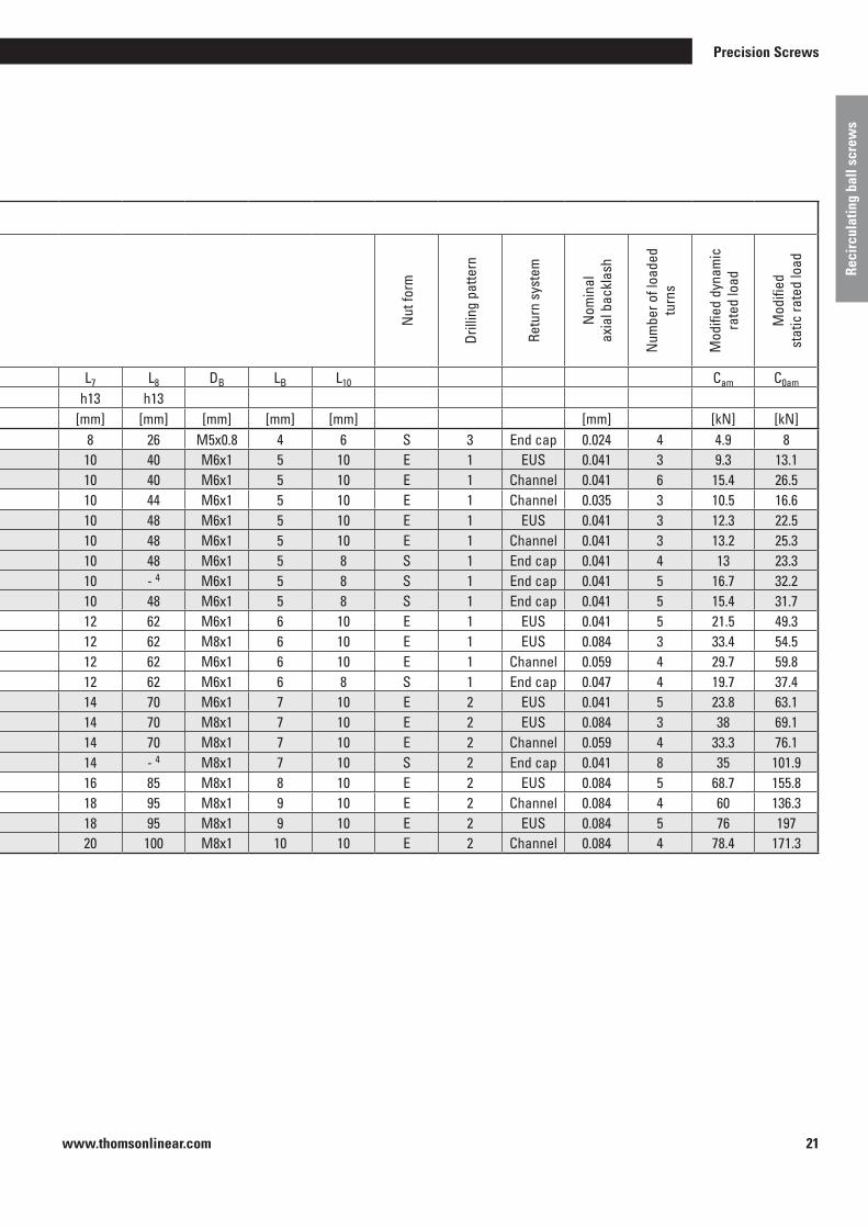
12 10 2 2 .000 0215200295 24 32 4 .5 40 27 .5 14 .5 9 .5 5 8 26 M5x0 .8 4 6 S 3 End cap 0 .024 4 4 .9 816 5 1 3 .500 0215200048 28 38 5 .5 48 42 32 10 0 10 40 M6x1 5 10 E 1 EUS 0 .041 3 9 .3 13 .116 10 2 3 .000 0215200168 28 38 5 .5 48 55 45 10 0 10 40 M6x1 5 10 E 1 Channel 0 .041 6 15 .4 26 .520 5 1 3 .500 0215200185 36 47 6 .6 58 42 32 10 0 10 44 M6x1 5 10 E 1 Channel 0 .035 3 10 .5 16 .625 5 1 3 .500 0215200051 40 51 6 .6 62 42 32 10 0 10 48 M6x1 5 10 E 1 EUS 0 .041 3 12 .3 22 .525 10 2 3 .500 0215200175 40 51 6 .6 62 55 45 16 0 10 48 M6x1 5 10 E 1 Channel 0 .041 3 13 .2 25 .325 20 4 3 .500 0215200200 40 51 6 .6 62 35 14 .5 4 10 .5 10 48 M6x1 5 8 S 1 End cap 0 .041 4 13 23 .325 25 5 3 .500 0215200201 40 51 6 .6 62 35 17 9 8 10 - 4 M6x1 5 8 S 1 End cap 0 .041 5 16 .7 32 .225 50 5 3 .500 0215200195 40 51 6 .6 62 58 38 10 10 10 48 M6x1 5 8 S 1 End cap 0 .041 5 15 .4 31 .732 5 1 3 .500 0215200054 50 65 9 80 55 43 10 0 12 62 M6x1 6 10 E 1 EUS 0 .041 5 21 .5 49 .332 10 1 7 .144 0215200087 53 1 65 9 80 69 57 16 0 12 62 M8x1 6 10 E 1 EUS 0 .084 3 33 .4 54 .532 20 2 5 .000 0215200191 53 1 65 9 80 80 68 16 0 12 62 M6x1 6 10 E 1 Channel 0 .059 4 29 .7 59 .832 32 4 3 .969 0215200235 50 65 9 80 42 21 12 9 12 62 M6x1 6 8 S 1 End cap 0 .047 4 19 .7 37 .440 5 1 3 .500 0215200056 63 78 9 93 57 43 10 0 14 70 M6x1 7 10 E 2 EUS 0 .041 5 23 .8 63 .140 10 1 7 .144 0215200356 63 78 9 93 71 57 16 0 14 70 M8x1 7 10 E 2 EUS 0 .084 3 38 69 .140 20 2 5 .000 0215200206 63 78 9 93 80 66 16 0 14 70 M8x1 7 10 E 2 Channel 0 .059 4 33 .3 76 .140 40 4 3 .500 0215200199 63 78 9 93 85 63 .5 16 7 .5 14 - 4 M8x1 7 10 S 2 End cap 0 .041 8 35 101 .950 10 1 7 .144 0215200074 75 93 11 110 95 79 16 0 16 85 M8x1 8 10 E 2 EUS 0 .084 5 68 .7 155 .850 20 2 7 .144 0215200212 85 1 103 1 11 125 95 77 22 0 18 95 M8x1 9 10 E 2 Channel 0 .084 4 60 136 .363 10 1 7 .144 0215200086 90 108 11 125 97 79 16 0 18 95 M8x1 9 10 E 2 EUS 0 .084 5 76 19763 20 2 7 .144 0215200240 95 115 13 .5 135 99 79 25 0 20 100 M8x1 10 10 E 2 Channel 0 .084 4 78 .4 171 .3
www.thomsonlinear.com 21
Precision Screws
Reci
rcul
atin
g ba
ll sc
rew
s
Nom
inal
dia
met
er
Lead
Num
ber o
f thr
eads
on
the
shaf
t
Ball
diam
eter
ID n
umbe
r
KGF-D style single nut
Nut
form
Drill
ing
patte
rn
Retu
rn s
yste
m
Nom
inal
ax
ial b
ackl
ash
Num
ber o
f loa
ded
turn
s
Mod
ified
dyn
amic
ra
ted
load
Mod
ified
st
atic
rate
d lo
ad
d0 Ph Dw D1 D4 D5 D6 L Lm L1 L3 L7 L8 DB LB L10 Cam C0am
g6 h13 h13 h13[mm] [mm] [mm] [mm] [mm] [mm] [mm] [mm] [mm] [mm] [mm] [mm] [mm] [mm] [mm] [mm] [mm] [kN] [kN]
12 10 2 2 .000 0215200295 24 32 4 .5 40 27 .5 14 .5 9 .5 5 8 26 M5x0 .8 4 6 S 3 End cap 0 .024 4 4 .9 816 5 1 3 .500 0215200048 28 38 5 .5 48 42 32 10 0 10 40 M6x1 5 10 E 1 EUS 0 .041 3 9 .3 13 .116 10 2 3 .000 0215200168 28 38 5 .5 48 55 45 10 0 10 40 M6x1 5 10 E 1 Channel 0 .041 6 15 .4 26 .520 5 1 3 .500 0215200185 36 47 6 .6 58 42 32 10 0 10 44 M6x1 5 10 E 1 Channel 0 .035 3 10 .5 16 .625 5 1 3 .500 0215200051 40 51 6 .6 62 42 32 10 0 10 48 M6x1 5 10 E 1 EUS 0 .041 3 12 .3 22 .525 10 2 3 .500 0215200175 40 51 6 .6 62 55 45 16 0 10 48 M6x1 5 10 E 1 Channel 0 .041 3 13 .2 25 .325 20 4 3 .500 0215200200 40 51 6 .6 62 35 14 .5 4 10 .5 10 48 M6x1 5 8 S 1 End cap 0 .041 4 13 23 .325 25 5 3 .500 0215200201 40 51 6 .6 62 35 17 9 8 10 - 4 M6x1 5 8 S 1 End cap 0 .041 5 16 .7 32 .225 50 5 3 .500 0215200195 40 51 6 .6 62 58 38 10 10 10 48 M6x1 5 8 S 1 End cap 0 .041 5 15 .4 31 .732 5 1 3 .500 0215200054 50 65 9 80 55 43 10 0 12 62 M6x1 6 10 E 1 EUS 0 .041 5 21 .5 49 .332 10 1 7 .144 0215200087 53 1 65 9 80 69 57 16 0 12 62 M8x1 6 10 E 1 EUS 0 .084 3 33 .4 54 .532 20 2 5 .000 0215200191 53 1 65 9 80 80 68 16 0 12 62 M6x1 6 10 E 1 Channel 0 .059 4 29 .7 59 .832 32 4 3 .969 0215200235 50 65 9 80 42 21 12 9 12 62 M6x1 6 8 S 1 End cap 0 .047 4 19 .7 37 .440 5 1 3 .500 0215200056 63 78 9 93 57 43 10 0 14 70 M6x1 7 10 E 2 EUS 0 .041 5 23 .8 63 .140 10 1 7 .144 0215200356 63 78 9 93 71 57 16 0 14 70 M8x1 7 10 E 2 EUS 0 .084 3 38 69 .140 20 2 5 .000 0215200206 63 78 9 93 80 66 16 0 14 70 M8x1 7 10 E 2 Channel 0 .059 4 33 .3 76 .140 40 4 3 .500 0215200199 63 78 9 93 85 63 .5 16 7 .5 14 - 4 M8x1 7 10 S 2 End cap 0 .041 8 35 101 .950 10 1 7 .144 0215200074 75 93 11 110 95 79 16 0 16 85 M8x1 8 10 E 2 EUS 0 .084 5 68 .7 155 .850 20 2 7 .144 0215200212 85 1 103 1 11 125 95 77 22 0 18 95 M8x1 9 10 E 2 Channel 0 .084 4 60 136 .363 10 1 7 .144 0215200086 90 108 11 125 97 79 16 0 18 95 M8x1 9 10 E 2 EUS 0 .084 5 76 19763 20 2 7 .144 0215200240 95 115 13 .5 135 99 79 25 0 20 100 M8x1 10 10 E 2 Channel 0 .084 4 78 .4 171 .3
www.thomsonlinear.com22
1 Dimension does not comply with DIN 69051; 2 Lubrication bore located anywhere on the circumference; 3 No wiper; 4 Round flange
Nuts for rolled ball screw shafts
See fold-out cover page for dimensions, form and drilling pattern
Nom
inal
dia
met
er
Lead
Num
ber o
f thr
eads
on
the
shaf
t
Ball
diam
eter
ID n
umbe
r
KGF-N style single nut
Nut
form
Drill
ing
patte
rn
Retu
rn s
yste
m
Nom
inal
ax
ial b
ackl
ash
Num
ber o
f loa
ded
turn
s
Mod
ified
dyn
amic
ra
ted
load
Mod
ified
st
atic
rate
d lo
ad
d0 Ph Dw D1 D4 D5 D6 L Lm L1 L3 L7 L8 DB LB L10 Cam C0am
g6 h13 h13 h13[mm] [mm] [mm] [mm] [mm] [mm] [mm] [mm] [mm] [mm] [mm] [mm] [mm] [mm] [mm] [mm] [mm] [kN] [kN]
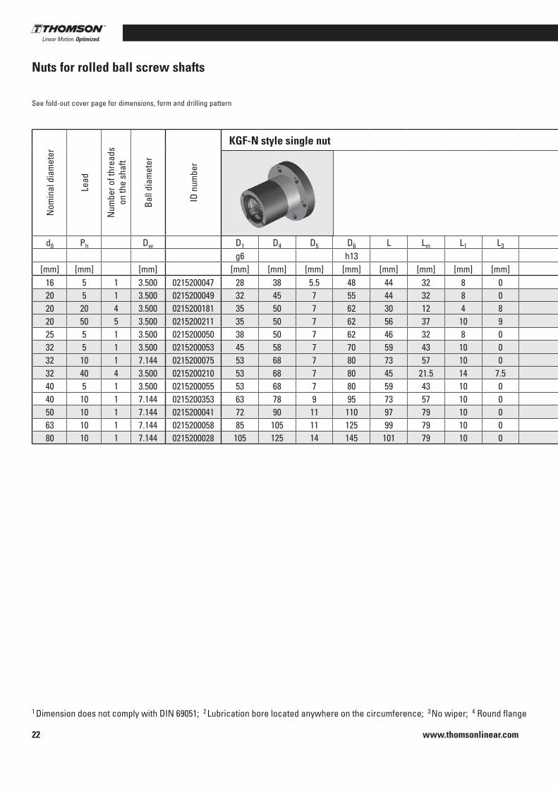
16 5 1 3 .500 0215200047 28 38 5 .5 48 44 32 8 0 12 - 4 M6x1 6 8 E 4 EUS 0 .041 3 9 .3 13 .120 5 1 3 .500 0215200049 32 45 7 55 44 32 8 0 12 - 4 M6x1 6 8 E 4 EUS 0 .041 3 10 .5 16 .620 20 4 3 .500 0215200181 35 50 7 62 30 12 4 8 10 - 4 M6x1 5 8 S 4 End cap 0 .041 4 11 .6 18 .420 50 5 3 .500 0215200211 35 50 7 62 56 37 10 9 10 - 4 M6x1 5 8 S 4 End cap 0 .041 5 13 24 .625 5 1 3 .500 0215200050 38 50 7 62 46 32 8 0 14 - 4 M6x1 7 8 E 4 EUS 0 .041 3 12 .3 22 .532 5 1 3 .500 0215200053 45 58 7 70 59 43 10 0 16 - 4 M6x1 8 8 E 4 EUS 0 .041 5 21 .5 49 .332 10 1 7 .144 0215200075 53 68 7 80 73 57 10 0 16 - 4 M8x1 8 8 E 4 EUS 0 .084 3 33 .4 54 .532 40 4 3 .500 0215200210 53 68 7 80 45 21 .5 14 7 .5 16 - 4 M6x1 8 10 S 4 End cap 0 .041 4 14 .9 32 .440 5 1 3 .500 0215200055 53 68 7 80 59 43 10 0 16 - 4 M6x1 8 8 E 4 EUS 0 .041 5 23 .8 63 .140 10 1 7 .144 0215200353 63 78 9 95 73 57 10 0 16 - 4 M8x1 8 8 E 4 EUS 0 .084 3 38 69 .150 10 1 7 .144 0215200041 72 90 11 110 97 79 10 0 18 - 4 M8x1 9 8 E 4 EUS 0 .084 5 68 .7 155 .863 10 1 7 .144 0215200058 85 105 11 125 99 79 10 0 20 - 4 M8x1 10 8 E 4 EUS 0 .084 5 76 19780 10 1 7 .144 0215200028 105 125 14 145 101 79 10 0 22 - 4 M8x1 11 8 E 4 EUS 0 .084 5 86 .25 262 .41

www.thomsonlinear.com 23
Precision Screws
Reci
rcul
atin
g ba
ll sc
rew
s
Nom
inal
dia
met
er
Lead
Num
ber o
f thr
eads
on
the
shaf
t
Ball
diam
eter
ID n
umbe
r
KGF-N style single nut
Nut
form
Drill
ing
patte
rn
Retu
rn s
yste
m
Nom
inal
ax
ial b
ackl
ash
Num
ber o
f loa
ded
turn
s
Mod
ified
dyn
amic
ra
ted
load
Mod
ified
st
atic
rate
d lo
ad
d0 Ph Dw D1 D4 D5 D6 L Lm L1 L3 L7 L8 DB LB L10 Cam C0am
g6 h13 h13 h13[mm] [mm] [mm] [mm] [mm] [mm] [mm] [mm] [mm] [mm] [mm] [mm] [mm] [mm] [mm] [mm] [mm] [kN] [kN]
16 5 1 3 .500 0215200047 28 38 5 .5 48 44 32 8 0 12 - 4 M6x1 6 8 E 4 EUS 0 .041 3 9 .3 13 .120 5 1 3 .500 0215200049 32 45 7 55 44 32 8 0 12 - 4 M6x1 6 8 E 4 EUS 0 .041 3 10 .5 16 .620 20 4 3 .500 0215200181 35 50 7 62 30 12 4 8 10 - 4 M6x1 5 8 S 4 End cap 0 .041 4 11 .6 18 .420 50 5 3 .500 0215200211 35 50 7 62 56 37 10 9 10 - 4 M6x1 5 8 S 4 End cap 0 .041 5 13 24 .625 5 1 3 .500 0215200050 38 50 7 62 46 32 8 0 14 - 4 M6x1 7 8 E 4 EUS 0 .041 3 12 .3 22 .532 5 1 3 .500 0215200053 45 58 7 70 59 43 10 0 16 - 4 M6x1 8 8 E 4 EUS 0 .041 5 21 .5 49 .332 10 1 7 .144 0215200075 53 68 7 80 73 57 10 0 16 - 4 M8x1 8 8 E 4 EUS 0 .084 3 33 .4 54 .532 40 4 3 .500 0215200210 53 68 7 80 45 21 .5 14 7 .5 16 - 4 M6x1 8 10 S 4 End cap 0 .041 4 14 .9 32 .440 5 1 3 .500 0215200055 53 68 7 80 59 43 10 0 16 - 4 M6x1 8 8 E 4 EUS 0 .041 5 23 .8 63 .140 10 1 7 .144 0215200353 63 78 9 95 73 57 10 0 16 - 4 M8x1 8 8 E 4 EUS 0 .084 3 38 69 .150 10 1 7 .144 0215200041 72 90 11 110 97 79 10 0 18 - 4 M8x1 9 8 E 4 EUS 0 .084 5 68 .7 155 .863 10 1 7 .144 0215200058 85 105 11 125 99 79 10 0 20 - 4 M8x1 10 8 E 4 EUS 0 .084 5 76 19780 10 1 7 .144 0215200028 105 125 14 145 101 79 10 0 22 - 4 M8x1 11 8 E 4 EUS 0 .084 5 86 .25 262 .41
www.thomsonlinear.com24
1 Dimension does not comply with DIN 69051; 2 Lubrication bore located anywhere on the circumference; 3 No wiper; 4 Round flange
Nuts for rolled ball screw shafts
See fold-out cover page for dimensions, form and drilling pattern
Nom
inal
dia
met
er
Lead
Num
ber o
f thr
eads
on
the
shaf
t
Ball
diam
eter
ID n
umbe
r KGM-D style single nut
Nut
form
Retu
rn s
yste
m
Nom
inal
ax
ial b
ackl
ash
Num
ber o
f loa
ded
turn
s
Mod
ified
dyn
amic
ra
ted
load
Mod
ified
st
atic
rate
d lo
ad
d0 Ph Dw D1 L L3 DB LB L9 L12 B T Cam C0am
g6 P9[mm] [mm] [mm] [mm] [mm] [mm] [mm] [mm] [mm] [mm] [mm] [mm] [mm] [kN] [kN]
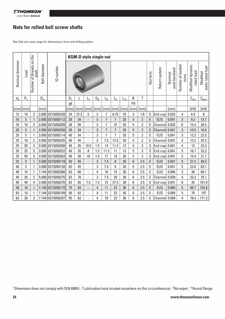
12 10 2 2 .000 0215050328 24 27 .5 5 2 7 8 .75 10 3 1 .8 S End cap 0 .024 4 4 .9 816 5 1 3 .500 0215050112 28 34 - 3 7 7 20 5 2 E EUS 0 .041 3 9 .3 13 .116 10 2 3 .000 0215050209 28 50 - 3 7 15 20 5 2 E Channel 0 .035 6 15 .4 26 .520 5 1 3 .500 0215050258 36 34 - 3 7 7 20 5 2 E Channel 0 .041 3 10 .5 16 .625 5 1 3 .500 0215050114 40 34 - 3 7 7 20 5 2 E EUS 0 .041 3 12 .3 22 .525 10 2 3 .500 0215050245 40 45 - 3 7 .5 12 .5 20 5 2 E Channel 0 .041 3 13 .2 25 .325 20 4 3 .500 0215050268 40 35 10 .5 1 .5 14 11 .5 12 5 3 S End cap 0 .041 4 13 23 .325 25 5 3 .500 0215050252 40 35 8 1 .5 11 .5 11 13 5 3 S End cap 0 .041 5 16 .7 32 .225 50 5 3 .500 0215050263 40 58 10 1 .5 17 19 20 5 3 S End cap 0 .041 5 15 .4 31 .732 5 1 3 .500 0215050118 50 45 - 3 7 .5 8 30 6 2 .5 E EUS 0 .041 5 21 .5 49 .340 5 1 3 .500 0215050120 63 45 - 3 7 .5 8 30 6 2 .5 E EUS 0 .041 5 23 .8 63 .140 10 1 7 .144 0215050366 63 60 - 4 10 15 30 6 2 .5 E EUS 0 .084 3 38 69 .140 20 2 5 .000 0215050270 63 70 - 3 7 .5 20 30 6 2 .5 E Channel 0 .059 4 33 .3 76 .140 40 4 3 .500 0215050276 63 85 7 .5 1 .5 15 27 .5 30 6 3 .5 S End cap 0 .041 8 35 101 .950 10 1 7 .144 0215050110 75 82 - 4 11 23 36 6 2 .5 E EUS 0 .084 5 68 .7 155 .863 10 1 7 .144 0215050109 90 82 - 4 11 23 36 6 2 .5 E EUS 0 .084 5 76 19763 20 2 7 .144 0215050297 95 82 - 4 10 23 36 6 2 .5 E Channel 0 .084 4 78 .4 171 .3

www.thomsonlinear.com 25
Precision Screws
Reci
rcul
atin
g ba
ll sc
rew
s
1 Dimension does not comply with DIN 69051; 2 Lubrication bore located anywhere on the circumference; 3 No wiper; 4 Round flange
Nom
inal
dia
met
er
Lead
Num
ber o
f thr
eads
on
the
shaf
t
Ball
diam
eter
ID n
umbe
r KGM-N style single nut
Nut
form
Retu
rn s
yste
m
Nom
inal
ax
ial b
ackl
ash
Num
ber o
f loa
ded
turn
s
Mod
ified
dyn
amic
ra
ted
load
Mod
ified
st
atic
rate
d lo
ad
d0 Ph Dw D1 L L3 DB LB L9 L12 B T Cam C0am
g6 P9[mm] [mm] [mm] [mm] [mm] [mm] [mm] [mm] [mm] [mm] [mm] [mm] [mm] [kN] [kN]
12 4 1 2 .000 0215050293 20 24 - 0 0 5 14 3 1 .8 E 3 Channel 0 .024 3 4 .9 6 .612 5 1 2 .000 0215050250 20 24 - 0 0 5 14 3 1 .8 E 3 Channel 0 .024 3 4 .4 6 .820 5 1 3 .500 0215050115 32 34 - 3 7 7 20 5 2 E EUS 0 .041 3 10 .5 16 .620 20 4 3 .500 0215050239 35 30 8 1 .5 11 .5 9 12 5 3 S End cap 0 .041 4 11 .6 18 .420 50 5 3 .500 0215050279 35 56 9 1 .5 16 18 20 5 3 S End cap 0 .041 5 13 24 .625 5 1 3 .500 0215050113 38 34 - 3 7 7 20 5 2 E EUS 0 .041 3 12 .3 22 .532 5 1 3 .500 0215050117 45 45 - 3 7 .5 8 30 6 2 .5 E EUS 0 .041 5 21 .5 49 .332 10 1 7 .144 0215050107 53 60 - 4 10 15 30 6 2 .5 E EUS 0 .084 3 33 .4 54 .532 20 2 5 .000 0215050255 53 70 - 3 7 .5 20 30 6 2 .5 E Channel 0 .059 4 29 .7 59 .832 40 4 3 .500 0215050275 53 45 7 .5 1 .5 13 10 25 6 4 S End cap 0 .041 4 14 .9 32 .440 5 1 3 .500 0215050119 53 45 - 3 7 .5 8 30 6 2 .5 E EUS 0 .041 5 23 .8 63 .150 10 1 7 .144 0215050111 72 82 - 4 11 23 36 6 2 .5 E EUS 0 .084 5 68 .7 155 .850 20 2 7 .144 0215050283 85 82 - 4 10 23 36 6 2 .5 E Channel 0 .084 4 60 136 .363 10 1 7 .144 0215050108 85 82 - 4 11 23 36 6 2 .5 E EUS 0 .084 5 76 19780 10 1 7 .144 0215050142 105 82 - 4 11 23 36 8 3 E EUS 0 .084 5 86 .3 262 .4

www.thomsonlinear.com26
End journals for loose bearings/fixed bearingsForm D, FThe type of bearing selected influences the stiffness of the lead screw system as a whole and also the rotational vibration and buckling behavior of the lead screw shaft . The required end jour-nals are made for the trapezoidal lead screw according to the vari-ous types of bearing .
Note: Bearings are not supplied.
Relief groove form F DIN 509 Relief groove form E DIN 509
Thread undercut DIN 76–B
Form D Dimensions [mm] Bearing
KGT D1 D2 L1 L2 L3 L4 L5 M1 B1xT1 ZKLF…2RS
1605, 1610 12 9 55 20 32 2 .5 16 M 12x1 3x1 .8 1255
2005, 2020, 2050 15 11 58 23 35 3 .5 16 M 15x1 4x2 .5 1560
2505, 2510, 2520, 2525, 2550 20 14 70 30 44 4 22 M 20x1 5x3 2068
3205, 3210, 3220, 3232, 3240 25 19 82 40 57 6 28 M 25x1 .5 6x3 .5 2575
4005, 4010, 4020, 4040 30 24 92 50 67 7 36 M 30x1 .5 8x4 3080
Form F Dimensions [mm] Bearing
KGT D1 D2 L1 L2 L3 L4 L5 M1 B1xT1 ZARN . . .LTN
2505, 2510, 2520, 2525, 2550 15 11 73 23 35 3 .5 16 M 15x1 4x2 .5 1545
3205, 3232, 3240 20 14 88 30 45 4 22 M 20x1 5x3 2052
3210, 3220 20 14 107 30 50 4 22 M 20x1 5x3 2062
4005 25 19 105 40 58 6 28 M 25x1 .5 6x3 .5 2557
4010, 4020, 4040 25 19 120 40 63 6 28 M 25x1 .5 6x3 .5 2572
5010, 5020 35 28 145 60 82 10 40 M 35x1 .5 8x4 3585
6310, 6320 40 36 175 80 103 8 .5 63 M 40x1 .5 10x5 4090
www.thomsonlinear.com 27
Precision Screws
Reci
rcul
atin
g ba
ll sc
rew
s
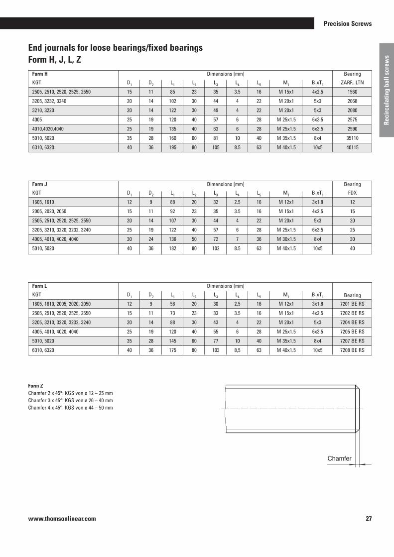
End journals for loose bearings/fixed bearingsForm H, J, L, Z
Form H Dimensions [mm] Bearing
KGT D1 D2 L1 L2 L3 L4 L5 M1 B1xT1 ZARF . . .LTN
2505, 2510, 2520, 2525, 2550 15 11 85 23 35 3 .5 16 M 15x1 4x2 .5 1560
3205, 3232, 3240 20 14 102 30 44 4 22 M 20x1 5x3 2068
3210, 3220 20 14 122 30 49 4 22 M 20x1 5x3 2080
4005 25 19 120 40 57 6 28 M 25x1 .5 6x3 .5 2575
4010,4020,4040 25 19 135 40 63 6 28 M 25x1 .5 6x3 .5 2590
5010, 5020 35 28 160 60 81 10 40 M 35x1 .5 8x4 35110
6310, 6320 40 36 195 80 105 8 .5 63 M 40x1 .5 10x5 40115
Form J Dimensions [mm] Bearing
KGT D1 D2 L1 L2 L3 L4 L5 M1 B1xT1 FDX
1605, 1610 12 9 88 20 32 2 .5 16 M 12x1 3x1 .8 12
2005, 2020, 2050 15 11 92 23 35 3 .5 16 M 15x1 4x2 .5 15
2505, 2510, 2520, 2525, 2550 20 14 107 30 44 4 22 M 20x1 5x3 20
3205, 3210, 3220, 3232, 3240 25 19 122 40 57 6 28 M 25x1 .5 6x3 .5 25
4005, 4010, 4020, 4040 30 24 136 50 72 7 36 M 30x1 .5 8x4 30
5010, 5020 40 36 182 80 102 8 .5 63 M 40x1 .5 10x5 40
Form L Dimensions [mm]
KGT D1 D2 L1 L2 L3 L4 L5 M1 B1xT1 Bearing
1605, 1610, 2005, 2020, 2050 12 9 58 20 30 2 .5 16 M 12x1 3x1,8 7201 BE RS
2505, 2510, 2520, 2525, 2550 15 11 73 23 33 3 .5 16 M 15x1 4x2 .5 7202 BE RS
3205, 3210, 3220, 3232, 3240 20 14 88 30 43 4 22 M 20x1 5x3 7204 BE RS
4005, 4010, 4020, 4040 25 19 120 40 55 6 28 M 25x1 .5 6x3 .5 7205 BE RS
5010, 5020 35 28 145 60 77 10 40 M 35x1 .5 8x4 7207 BE RS
6310, 6320 40 36 175 80 103 8,5 63 M 40x1 .5 10x5 7208 BE RS
Form ZChamfer 2 x 45°: KGS von ø 12 – 25 mmChamfer 3 x 45°: KGS von ø 26 – 40 mmChamfer 4 x 45°: KGS von ø 44 – 50 mm
Chamfer

www.thomsonlinear.com28
End journals for loose bearings/fixed bearingsForm S, T, W, G, K
Relief groove form E DIN 509 Groove for circlip DIN 471
Form S Dimensions [mm]
KGT D1 L1 L2 Spacer bushing Bearing
1605, 1610 12 40 45 18x12 .1x24 6001 RS
2005, 2020, 2050 15 46 51 21x15 .1x28 6002 RS
2505, 2510, 2520, 2525, 2550 20 53 58 27x20 .1x29 6004 RS
3205, 3210, 3220 3232, 3240 25 53 58 32x25 .1x23 6205 RS
4005, 4010, 4020, 4040 30 60 68 40x30 .1x28 6206 RS
5010, 5020 40 80 88 50x40 .1x44 6208 RS
6310, 6320 55 102 110 65x55 .1x60 6211 RS
Form T Dimensions [mm]
KGT D1 L1 L2 Inner ring Needle bearing
1605, 1610 12 40 45 2 IR 12x16x20 HK 1614 RS
2005, 2020, 2050 15 46 51 2 IR 15x20x23 HK 2018 RS
2505, 2510, 2520, 2525, 2550 20 53 58 2 LR 20x25x26 .5 HK 2518 RS
3205, 3210, 3220, 3232, 3240 25 53 58 2 LR 25x30x26 .5 HK 3018 RS
4005, 4010, 4020, 4040 30 60 68 2 LR 30x35x30 HK 3518 RS
5010, 5020 40 80 88 4 LR 40x45x20 HK 4518 RS
Form W Dimensions [mm]
KGT D1 L1 L2 Bearing
1605, 1610 12 8 12 6001 RS
2005, 2020, 2050 15 9 13 6002 RS
2505, 2510, 2520, 2525, 2550 20 12 16 6004 RS
3205, 3210, 3220, 3240 25 15 20 6205 RS
4005, 4010, 4020, 4040 30 16 21 6206 RS
5010, 5020 40 18 25 6208 RS
6310 55 21 29 6211 RS
Form G: End journal annealed to costumer‘s specification .
Form K: Special production per customer‘s drawing .

www.thomsonlinear.com 29
Precision Screws
Reci
rcul
atin
g ba
ll sc
rew
s
Notes

www.thomsonlinear.com30
General information regarding whirled/ground ball screws
Method of manufacture
■ Whirled (standard)
Whirled ball screw shafts are produced using cutting plates in spe-cial materials . In this process, the raceway is cut into the previously hardened raw material in a single pass, or multiple passes for large balls .
■ Ground
Depending on the ball size, the raceway of ground ball screw shafts is either ground directly into the solid blank, or the blank is first whirled and then ground .
Tolerance classes
■ Whirled (standard)
Whirled ball screw shafts are currently available in classes P3, P4 and P5 and also T5 and T7
■ Ground
Ground shafts are available on request .
whirled
Process Nominal diameter [mm]
Thread length[mm]
Tolerance class[DIN]
P4a 8600
A 8600 T7Ø80–Ø160
Ø16–Ø80P3 4100
A 4100 P5/T5
www.thomsonlinear.com 31
Precision Screws
Reci
rcul
atin
g ba
ll sc
rew
s
Thomson Neff whirled shafts are setting new standards: ■ Higher or at least identical surface quality of the raceway compared with ground ball screws
■ Better running in behavior, i .e . the ball screw nut's preloading is maintained for longer
■ Greater profile accuracy thanks to geometrically defined cutting of the cutting plates
■ Greater service life thanks to the points listed above
Technical data
Thread: Gothic thread profile
Diameter: 16–160mm (other sizes on request)
Number of starts: 1–2
Lead: As customer requirement
Thread direction: Clockwise, counter-clockwise, right-hand/left-hand shaft
End journal: As customer requirement
www.thomsonlinear.com32
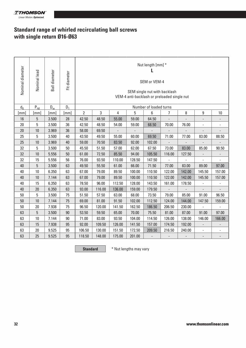
Standard range of whirled recirculating ball screws with single return Ø16-Ø63
www.thomsonlinear.com
Nom
inal
dia
met
er
Nom
inal
lead
Ball
diam
eter
Fit d
iam
eter
Nut length [mm] *L
SEM or VEM-4
SEM single nut with backlashVEM-4 anti-backlash or preloaded single nut
Nut length [mm] *L
VEM-2
VEM-2 preloaded single nut
Nut length [mm] *L
VDM
VDM Preloaded double nut
d0 Ph0 Dw D1 Number of loaded turns Number of loaded turns Number of loaded turns[mm] [mm] [mm] [mm] 2 3 4 5 6 7 8 9 10 2+2 3+3 4+4 5+5 6+6 7+7 8+8 2 3 4 5 6 7 8
16 5 3 .500 28 42 .50 48 .50 55 .00 59 .00 64 .50 - - - - 55 .00 68 .50 - - - - - - - - - - - -20 5 3 .500 36 42 .50 48 .50 54 .00 59 .00 68 .50 70 .00 76 .00 - - 53 .50 68 .50 80 .00 - - - - - - - - - - -20 10 3 .969 36 58 .00 69 .50 - - - - - - - - - - - - - - - - - - - - -25 5 3 .500 40 43 .50 49 .50 55 .00 60 .00 69 .50 71 .00 77 .00 83 .00 88 .50 58 .50 69 .50 81 .00 91 .00 - - - - - - - - - -25 10 3 .969 40 59 .00 70 .50 83 .50 92 .00 102 .00 - - - - 83 .50 110 .50 - - - - - - - - - - - -32 5 3 .500 50 45 .50 51 .50 57 .00 62 .00 67 .50 73 .00 83 .00 85 .00 90 .50 60 .50 71 .50 83 .00 93 .00 103 .00 115 .00 - 75 .00 87 .00 97 .50 108 .00 118 .50 130 .00 142 .0032 10 5 .556 50 61 .00 72 .50 85 .50 94 .00 105 .50 116 .00 127 .50 - - 85 .50 105 .50 129 .00 - - - - 105 .50 129 .00 150 .50 171 .50 192 .00 215 .50 239 .0032 15 5 .556 56 76 .00 93 .50 110 .00 128 .50 147 .50 - - - - 121 .00 153 .50 - - - - - 133 .50 168 .50 201 .00 232 .50 263 .50 - -40 5 3 .500 63 49 .50 55 .50 61 .00 66 .00 71 .50 77 .00 83 .00 89 .00 97 .00 64 .50 75 .50 87 .00 97 .00 111 .00 119 .00 130 .50 79 .00 91 .00 101 .50 112 .00 122 .50 134 .00 146 .0040 10 6 .350 63 67 .00 79 .00 89 .50 100 .00 110 .50 122 .00 142 .00 145 .50 157 .00 97 .00 119 .00 142 .00 162 .00 - - - 114 .00 137 .50 159 .00 180 .00 201 .00 224 .00 247 .5040 10 7 .144 63 67 .00 79 .00 89 .50 100 .00 110 .50 122 .00 142 .00 145 .50 157 .00 97 .00 119 .00 142 .00 162 .00 - - - 114 .00 137 .50 159 .00 180 .00 201 .00 224 .00 247 .5040 15 6 .350 63 78 .50 96 .00 112 .50 128 .00 143 .50 161 .00 178 .50 - - 123 .50 156 .00 191 .00 - - - - 136 .50 171 .50 204 .00 235 .50 266 .50 301 .50 336 .5040 20 6 .350 63 93 .00 116 .00 136 .00 159 .00 179 .50 - - - - 136 .00 196 .00 - - - - - 165 .00 212 .00 255 .00 297 .00 338 .50 - -50 5 3 .500 75 51 .50 57 .50 63 .00 68 .00 73 .50 79 .00 85 .00 91 .00 96 .50 66 .50 77 .50 89 .00 99 .00 109 .00 121 .00 132 .50 81 .00 93 .00 103 .50 114 .00 124 .50 136 .00 148 .0050 10 7 .144 75 69 .00 81 .00 91 .50 102 .00 112 .50 124 .00 144 .00 147 .50 159 .00 99 .00 120 .50 144 .00 164 .00 184 .00 - - 116 .00 139 .50 161 .00 182 .00 203 .00 226 .00 249 .5050 20 7 .938 75 96 .50 120 .00 141 .50 162 .50 186 .50 206 .50 230 .00 - - 156 .50 186 .50 233 .50 - - - - 170 .50 217 .00 260 .50 302 .50 343 .50 390 .50 437 .0063 5 3 .500 90 53 .50 59 .50 65 .00 70 .00 75 .50 81 .00 87 .00 91 .00 97 .00 68 .50 79 .50 91 .00 101 .00 111 .00 123 .00 - 89 .00 101 .00 111 .50 122 .00 132 .50 144 .00 156 .0063 10 7 .144 90 71 .00 83 .00 93 .50 104 .00 114 .50 126 .00 138 .00 146 .00 166 .00 101 .00 123 .00 146 .00 166 .00 186 .00 - - 124 .00 147 .50 169 .00 190 .00 211 .00 234 .00 257 .5063 15 7 .938 95 92 .00 109 .50 126 .00 141 .50 157 .00 174 .50 192 .00 - - 137 .00 169 .50 199 .50 - - - - 159 .50 194 .50 227 .00 258 .50 289 .50 324 .50 359 .5063 20 9 .525 95 106 .50 130 .00 151 .50 172 .50 209 .50 216 .50 240 .00 - - 166 .00 209 .50 259 .50 - - - - 188 .50 235 .00 278 .50 320 .50 361 .50 408 .50 455 .0063 25 9 .525 95 118 .50 148 .00 175 .00 201 .00 - - - - - 193 .50 - - - - - - 212 .50 271 .00 325 .00 377 .50 - - -
Standard * Nut lengths may vary
www.thomsonlinear.com 33
Precision Screws
Reci
rcul
atin
g ba
ll sc
rew
s
www.thomsonlinear.com
Nom
inal
dia
met
er
Nom
inal
lead
Ball
diam
eter
Fit d
iam
eter
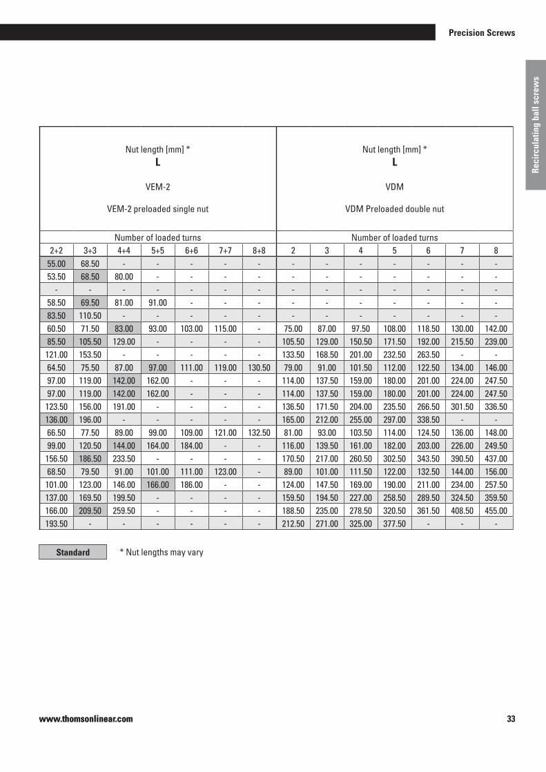
Nut length [mm] *L
SEM or VEM-4
SEM single nut with backlashVEM-4 anti-backlash or preloaded single nut
Nut length [mm] *L
VEM-2
VEM-2 preloaded single nut
Nut length [mm] *L
VDM
VDM Preloaded double nut
d0 Ph0 Dw D1 Number of loaded turns Number of loaded turns Number of loaded turns[mm] [mm] [mm] [mm] 2 3 4 5 6 7 8 9 10 2+2 3+3 4+4 5+5 6+6 7+7 8+8 2 3 4 5 6 7 8
16 5 3 .500 28 42 .50 48 .50 55 .00 59 .00 64 .50 - - - - 55 .00 68 .50 - - - - - - - - - - - -20 5 3 .500 36 42 .50 48 .50 54 .00 59 .00 68 .50 70 .00 76 .00 - - 53 .50 68 .50 80 .00 - - - - - - - - - - -20 10 3 .969 36 58 .00 69 .50 - - - - - - - - - - - - - - - - - - - - -25 5 3 .500 40 43 .50 49 .50 55 .00 60 .00 69 .50 71 .00 77 .00 83 .00 88 .50 58 .50 69 .50 81 .00 91 .00 - - - - - - - - - -25 10 3 .969 40 59 .00 70 .50 83 .50 92 .00 102 .00 - - - - 83 .50 110 .50 - - - - - - - - - - - -32 5 3 .500 50 45 .50 51 .50 57 .00 62 .00 67 .50 73 .00 83 .00 85 .00 90 .50 60 .50 71 .50 83 .00 93 .00 103 .00 115 .00 - 75 .00 87 .00 97 .50 108 .00 118 .50 130 .00 142 .0032 10 5 .556 50 61 .00 72 .50 85 .50 94 .00 105 .50 116 .00 127 .50 - - 85 .50 105 .50 129 .00 - - - - 105 .50 129 .00 150 .50 171 .50 192 .00 215 .50 239 .0032 15 5 .556 56 76 .00 93 .50 110 .00 128 .50 147 .50 - - - - 121 .00 153 .50 - - - - - 133 .50 168 .50 201 .00 232 .50 263 .50 - -40 5 3 .500 63 49 .50 55 .50 61 .00 66 .00 71 .50 77 .00 83 .00 89 .00 97 .00 64 .50 75 .50 87 .00 97 .00 111 .00 119 .00 130 .50 79 .00 91 .00 101 .50 112 .00 122 .50 134 .00 146 .0040 10 6 .350 63 67 .00 79 .00 89 .50 100 .00 110 .50 122 .00 142 .00 145 .50 157 .00 97 .00 119 .00 142 .00 162 .00 - - - 114 .00 137 .50 159 .00 180 .00 201 .00 224 .00 247 .5040 10 7 .144 63 67 .00 79 .00 89 .50 100 .00 110 .50 122 .00 142 .00 145 .50 157 .00 97 .00 119 .00 142 .00 162 .00 - - - 114 .00 137 .50 159 .00 180 .00 201 .00 224 .00 247 .5040 15 6 .350 63 78 .50 96 .00 112 .50 128 .00 143 .50 161 .00 178 .50 - - 123 .50 156 .00 191 .00 - - - - 136 .50 171 .50 204 .00 235 .50 266 .50 301 .50 336 .5040 20 6 .350 63 93 .00 116 .00 136 .00 159 .00 179 .50 - - - - 136 .00 196 .00 - - - - - 165 .00 212 .00 255 .00 297 .00 338 .50 - -50 5 3 .500 75 51 .50 57 .50 63 .00 68 .00 73 .50 79 .00 85 .00 91 .00 96 .50 66 .50 77 .50 89 .00 99 .00 109 .00 121 .00 132 .50 81 .00 93 .00 103 .50 114 .00 124 .50 136 .00 148 .0050 10 7 .144 75 69 .00 81 .00 91 .50 102 .00 112 .50 124 .00 144 .00 147 .50 159 .00 99 .00 120 .50 144 .00 164 .00 184 .00 - - 116 .00 139 .50 161 .00 182 .00 203 .00 226 .00 249 .5050 20 7 .938 75 96 .50 120 .00 141 .50 162 .50 186 .50 206 .50 230 .00 - - 156 .50 186 .50 233 .50 - - - - 170 .50 217 .00 260 .50 302 .50 343 .50 390 .50 437 .0063 5 3 .500 90 53 .50 59 .50 65 .00 70 .00 75 .50 81 .00 87 .00 91 .00 97 .00 68 .50 79 .50 91 .00 101 .00 111 .00 123 .00 - 89 .00 101 .00 111 .50 122 .00 132 .50 144 .00 156 .0063 10 7 .144 90 71 .00 83 .00 93 .50 104 .00 114 .50 126 .00 138 .00 146 .00 166 .00 101 .00 123 .00 146 .00 166 .00 186 .00 - - 124 .00 147 .50 169 .00 190 .00 211 .00 234 .00 257 .5063 15 7 .938 95 92 .00 109 .50 126 .00 141 .50 157 .00 174 .50 192 .00 - - 137 .00 169 .50 199 .50 - - - - 159 .50 194 .50 227 .00 258 .50 289 .50 324 .50 359 .5063 20 9 .525 95 106 .50 130 .00 151 .50 172 .50 209 .50 216 .50 240 .00 - - 166 .00 209 .50 259 .50 - - - - 188 .50 235 .00 278 .50 320 .50 361 .50 408 .50 455 .0063 25 9 .525 95 118 .50 148 .00 175 .00 201 .00 - - - - - 193 .50 - - - - - - 212 .50 271 .00 325 .00 377 .50 - - -
Standard * Nut lengths may vary

www.thomsonlinear.com34
Standard range of whirled recirculating ball screws with single return Ø16-Ø63
Nom
inal
dia
met
er
Nom
inal
lead
Ball
diam
eter
Fit d
iam
eter Modified dynamic rated load [kN]
Cam
Modified static rated load [kN]
C0am
d0 Ph0 Dw D1 Number of loaded turns Number of loaded turns[mm] [mm] [mm] [mm] 2 3 4 5 6 7 8 9 10 2 3 4 5 6 7 8 9 10
16 5 3 .500 28 6 .70 9 .40 12 .10 14 .70 17 .20 - - - - 7 .20 10 .90 14 .50 18 .10 21 .70 - - - -20 5 3 .500 36 8 .10 11 .50 14 .80 17 .90 20 .90 23 .90 26 .80 - - 10 .30 15 .50 20 .70 25 .80 31 .00 36 .20 41 .30 - -20 10 3 .969 36 8 .70 12 .40 - - - - - - - 10 .30 15 .40 - - - - - - -25 5 3 .500 40 9 .60 13 .60 17 .40 21 .10 24 .70 28 .20 31 .60 35 .00 38 .30 14 .20 21 .30 28 .40 35 .50 42 .70 49 .80 56 .90 64 .00 71 .1025 10 3 .969 40 10 .40 14 .80 19 .00 23 .00 26 .90 - - - - 14 .30 21 .40 28 .50 35 .60 42 .80 - - - -32 5 3 .500 50 10 .90 15 .50 19 .80 24 .00 28 .10 32 .10 36 .00 39 .80 43 .60 18 .90 28 .40 37 .90 47 .30 56 .80 66 .30 75 .70 85 .20 94 .7032 10 5 .556 50 18 .60 26 .40 33 .80 40 .90 47 .90 54 .70 61 .30 - - 26 .00 39 .00 52 .00 65 .00 78 .00 91 .00 104 .00 - -32 15 5 .556 56 17 .60 24 .90 31 .90 38 .70 45 .20 - - - - 24 .00 36 .00 48 .00 60 .00 72 .00 - - - -40 5 3 .500 63 12 .20 17 .30 22 .10 26 .80 31 .40 35 .80 40 .20 44 .50 48 .70 24 .40 36 .70 48 .90 61 .10 73 .30 85 .60 97 .80 110 .00 122 .2040 10 6 .350 63 29 .70 42 .10 53 .90 65 .30 76 .40 87 .20 97 .80 108 .20 118 .50 46 .50 69 .70 93 .00 116 .20 139 .40 162 .70 185 .90 209 .20 232 .4040 10 7 .144 63 35 .70 50 .60 64 .90 78 .60 91 .90 104 .90 117 .70 130 .30 142 .60 54 .50 81 .80 109 .00 136 .30 163 .50 190 .80 218 .00 245 .30 272 .5040 15 6 .350 63 29 .50 41 .90 53 .60 65 .00 76 .00 86 .80 97 .30 - - 46 .30 69 .50 92 .60 115 .80 138 .90 162 .10 185 .20 - -40 20 6 .350 63 28 .00 39 .70 50 .90 61 .60 72 .10 - - - - 43 .00 64 .50 86 .00 107 .50 129 .00 - - - -50 5 3 .500 75 12 .70 18 .00 23 .00 27 .90 32 .60 37 .20 41 .80 46 .20 50 .60 31 .50 47 .30 63 .10 78 .80 94 .60 110 .30 126 .10 141 .90 157 .6050 10 7 .144 75 38 .00 53 .90 69 .00 83 .60 97 .80 111 .70 125 .30 138 .60 151 .80 71 .10 106 .60 142 .20 177 .70 213 .20 248 .80 284 .30 319 .80 355 .4050 20 7 .938 75 41 .20 58 .40 74 .80 90 .60 106 .00 121 .00 135 .80 - - 72 .30 108 .40 144 .60 180 .70 216 .90 253 .00 289 .20 - -63 5 3 .500 90 14 .10 20 .00 25 .60 31 .00 36 .30 41 .50 46 .50 51 .50 56 .40 41 .00 61 .50 82 .00 102 .40 122 .90 143 .40 163 .90 184 .40 204 .9063 10 7 .144 90 43 .90 62 .20 79 .60 96 .50 112 .90 128 .90 144 .50 159 .90 175 .10 95 .90 143 .80 191 .70 239 .70 287 .60 335 .50 383 .50 431 .40 479 .3063 15 7 .938 95 49 .60 70 .30 90 .00 109 .00 127 .50 145 .60 163 .30 - - 102 .90 154 .40 205 .90 257 .30 308 .80 360 .30 411 .70 - -63 20 9 .525 95 61 .90 87 .70 112 .30 136 .00 159 .10 181 .70 203 .80 - - 118 .60 177 .90 237 .30 296 .60 355 .90 415 .20 474 .50 - -63 25 9 .525 95 59 .20 83 .90 107 .40 130 .20 - - - - - 111 .40 167 .00 222 .70 278 .40 - - - - -
Standard

www.thomsonlinear.com 35
Precision Screws
Reci
rcul
atin
g ba
ll sc
rew
s
Nom
inal
dia
met
er
Nom
inal
lead
Ball
diam
eter
Fit d
iam
eter Modified dynamic rated load [kN]
Cam
Modified static rated load [kN]
C0am
d0 Ph0 Dw D1 Number of loaded turns Number of loaded turns[mm] [mm] [mm] [mm] 2 3 4 5 6 7 8 9 10 2 3 4 5 6 7 8 9 10
16 5 3 .500 28 6 .70 9 .40 12 .10 14 .70 17 .20 - - - - 7 .20 10 .90 14 .50 18 .10 21 .70 - - - -20 5 3 .500 36 8 .10 11 .50 14 .80 17 .90 20 .90 23 .90 26 .80 - - 10 .30 15 .50 20 .70 25 .80 31 .00 36 .20 41 .30 - -20 10 3 .969 36 8 .70 12 .40 - - - - - - - 10 .30 15 .40 - - - - - - -25 5 3 .500 40 9 .60 13 .60 17 .40 21 .10 24 .70 28 .20 31 .60 35 .00 38 .30 14 .20 21 .30 28 .40 35 .50 42 .70 49 .80 56 .90 64 .00 71 .1025 10 3 .969 40 10 .40 14 .80 19 .00 23 .00 26 .90 - - - - 14 .30 21 .40 28 .50 35 .60 42 .80 - - - -32 5 3 .500 50 10 .90 15 .50 19 .80 24 .00 28 .10 32 .10 36 .00 39 .80 43 .60 18 .90 28 .40 37 .90 47 .30 56 .80 66 .30 75 .70 85 .20 94 .7032 10 5 .556 50 18 .60 26 .40 33 .80 40 .90 47 .90 54 .70 61 .30 - - 26 .00 39 .00 52 .00 65 .00 78 .00 91 .00 104 .00 - -32 15 5 .556 56 17 .60 24 .90 31 .90 38 .70 45 .20 - - - - 24 .00 36 .00 48 .00 60 .00 72 .00 - - - -40 5 3 .500 63 12 .20 17 .30 22 .10 26 .80 31 .40 35 .80 40 .20 44 .50 48 .70 24 .40 36 .70 48 .90 61 .10 73 .30 85 .60 97 .80 110 .00 122 .2040 10 6 .350 63 29 .70 42 .10 53 .90 65 .30 76 .40 87 .20 97 .80 108 .20 118 .50 46 .50 69 .70 93 .00 116 .20 139 .40 162 .70 185 .90 209 .20 232 .4040 10 7 .144 63 35 .70 50 .60 64 .90 78 .60 91 .90 104 .90 117 .70 130 .30 142 .60 54 .50 81 .80 109 .00 136 .30 163 .50 190 .80 218 .00 245 .30 272 .5040 15 6 .350 63 29 .50 41 .90 53 .60 65 .00 76 .00 86 .80 97 .30 - - 46 .30 69 .50 92 .60 115 .80 138 .90 162 .10 185 .20 - -40 20 6 .350 63 28 .00 39 .70 50 .90 61 .60 72 .10 - - - - 43 .00 64 .50 86 .00 107 .50 129 .00 - - - -50 5 3 .500 75 12 .70 18 .00 23 .00 27 .90 32 .60 37 .20 41 .80 46 .20 50 .60 31 .50 47 .30 63 .10 78 .80 94 .60 110 .30 126 .10 141 .90 157 .6050 10 7 .144 75 38 .00 53 .90 69 .00 83 .60 97 .80 111 .70 125 .30 138 .60 151 .80 71 .10 106 .60 142 .20 177 .70 213 .20 248 .80 284 .30 319 .80 355 .4050 20 7 .938 75 41 .20 58 .40 74 .80 90 .60 106 .00 121 .00 135 .80 - - 72 .30 108 .40 144 .60 180 .70 216 .90 253 .00 289 .20 - -63 5 3 .500 90 14 .10 20 .00 25 .60 31 .00 36 .30 41 .50 46 .50 51 .50 56 .40 41 .00 61 .50 82 .00 102 .40 122 .90 143 .40 163 .90 184 .40 204 .9063 10 7 .144 90 43 .90 62 .20 79 .60 96 .50 112 .90 128 .90 144 .50 159 .90 175 .10 95 .90 143 .80 191 .70 239 .70 287 .60 335 .50 383 .50 431 .40 479 .3063 15 7 .938 95 49 .60 70 .30 90 .00 109 .00 127 .50 145 .60 163 .30 - - 102 .90 154 .40 205 .90 257 .30 308 .80 360 .30 411 .70 - -63 20 9 .525 95 61 .90 87 .70 112 .30 136 .00 159 .10 181 .70 203 .80 - - 118 .60 177 .90 237 .30 296 .60 355 .90 415 .20 474 .50 - -63 25 9 .525 95 59 .20 83 .90 107 .40 130 .20 - - - - - 111 .40 167 .00 222 .70 278 .40 - - - - -
Standard
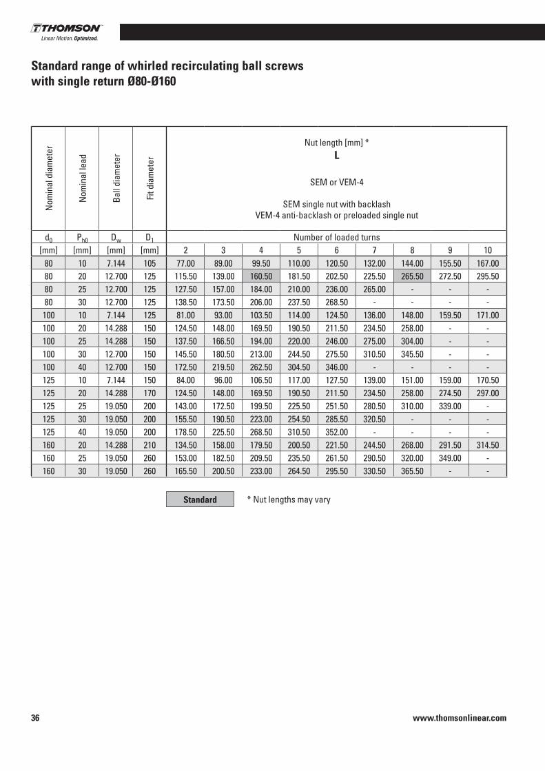
www.thomsonlinear.com36
Standard range of whirled recirculating ball screws with single return Ø80-Ø160
Nom
inal
dia
met
er
Nom
inal
lead
Ball
diam
eter
Fit d
iam
eter
Nut length [mm] *L
SEM or VEM-4
SEM single nut with backlash VEM-4 anti-backlash or preloaded single nut
Nut length [mm] *L
VEM-2
VEM-2 preloaded single nut
Nut length [mm] *L
VDM
VDM Preloaded double nut
d0 Ph0 Dw D1 Number of loaded turns Number of loaded turns Number of loaded turns[mm] [mm] [mm] [mm] 2 3 4 5 6 7 8 9 10 2+2 3+3 4+4 5+5 6+6 7+7 8+8 2 3 4 5 6 7 8
80 10 7 .144 105 77 .00 89 .00 99 .50 110 .00 120 .50 132 .00 144 .00 155 .50 167 .00 107 .00 129 .00 152 .00 172 .00 192 .00 215 .50 239 .00 131 .00 154 .50 176 .00 197 .00 218 .00 241 .00 264 .5080 20 12 .700 125 115 .50 139 .00 160 .50 181 .50 202 .50 225 .50 265 .50 272 .50 295 .50 175 .50 219 .00 265 .50 299 .00 - - - 201 .50 248 .50 291 .50 333 .50 375 .00 421 .50 468 .5080 25 12 .700 125 127 .50 157 .00 184 .00 210 .00 236 .00 265 .00 - - - 202 .50 257 .00 - - - - - 225 .50 284 .00 338 .00 390 .50 442 .00 500 .50 -80 30 12 .700 125 138 .50 173 .50 206 .00 237 .50 268 .50 - - - - 228 .50 293 .50 - - - - - 247 .50 317 .50 382 .50 445 .50 507 .50 - -
100 10 7 .144 125 81 .00 93 .00 103 .50 114 .00 124 .50 136 .00 148 .00 159 .50 171 .00 111 .00 133 .00 156 .00 184 .00 196 .00 219 .50 243 .00 150 .00 173 .50 195 .00 216 .00 237 .00 260 .00 283 .50100 20 14 .288 150 124 .50 148 .00 169 .50 190 .50 211 .50 234 .50 258 .00 - - - - - - - - - 217 .50 264 .50 307 .50 349 .50 391 .00 437 .50 484 .50100 25 14 .288 150 137 .50 166 .50 194 .00 220 .00 246 .00 275 .00 304 .00 - - - - - - - - - 243 .00 301 .50 355 .50 408 .00 459 .50 518 .00 576 .50100 30 12 .700 150 145 .50 180 .50 213 .00 244 .50 275 .50 310 .50 345 .50 - - 230 .50 300 .50 370 .50 - - - - 259 .50 329 .50 394 .50 457 .50 519 .50 589 .50 659 .50100 40 12 .700 150 172 .50 219 .50 262 .50 304 .50 346 .00 - - - - 286 .00 379 .50 - - - - - 313 .50 407 .00 493 .50 577 .50 660 .50 - -125 10 7 .144 150 84 .00 96 .00 106 .50 117 .00 127 .50 139 .00 151 .00 159 .00 170 .50 112 .50 136 .00 159 .00 179 .00 199 .00 222 .50 - 153 .00 176 .50 198 .00 219 .00 240 .00 263 .00 286 .50125 20 14 .288 170 124 .50 148 .00 169 .50 190 .50 211 .50 234 .50 258 .00 274 .50 297 .00 - - - - - - - 217 .50 264 .50 307 .50 349 .50 391 .00 437 .50 484 .50125 25 19 .050 200 143 .00 172 .50 199 .50 225 .50 251 .50 280 .50 310 .00 339 .00 - - - - - - - - 254 .50 313 .00 367 .00 419 .50 471 .50 529 .50 588 .00125 30 19 .050 200 155 .50 190 .50 223 .00 254 .50 285 .50 320 .50 - - - - - - - - - - 279 .50 349 .50 414 .50 477 .50 539 .50 609 .50 -125 40 19 .050 200 178 .50 225 .50 268 .50 310 .50 352 .00 - - - - - - - - - - - 325 .50 419 .00 505 .50 589 .50 672 .50 - -160 20 14 .288 210 134 .50 158 .00 179 .50 200 .50 221 .50 244 .50 268 .00 291 .50 314 .50 - - - - - - - 227 .50 274 .50 317 .50 359 .50 401 .00 447 .50 494 .50160 25 19 .050 260 153 .00 182 .50 209 .50 235 .50 261 .50 290 .50 320 .00 349 .00 - - - - - - - - 264 .50 323 .00 377 .00 429 .50 481 .50 539 .50 598 .00160 30 19 .050 260 165 .50 200 .50 233 .00 264 .50 295 .50 330 .50 365 .50 - - - - - - - - - 289 .50 359 .50 424 .50 487 .50 549 .50 619 .50 689 .50
Standard * Nut lengths may vary
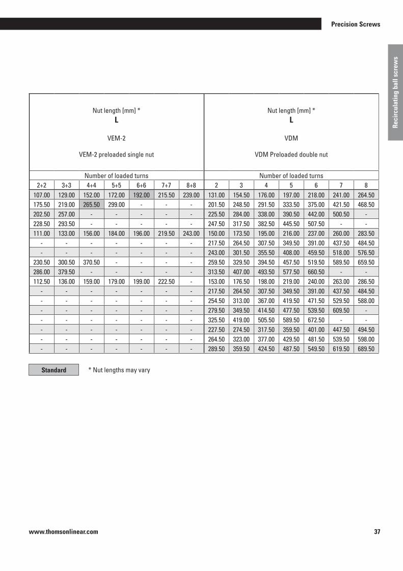
www.thomsonlinear.com 37
Precision Screws
Reci
rcul
atin
g ba
ll sc
rew
s
Nom
inal
dia
met
er
Nom
inal
lead
Ball
diam
eter
Fit d
iam
eter
Nut length [mm] *L
SEM or VEM-4
SEM single nut with backlash VEM-4 anti-backlash or preloaded single nut
Nut length [mm] *L
VEM-2
VEM-2 preloaded single nut
Nut length [mm] *L
VDM
VDM Preloaded double nut
d0 Ph0 Dw D1 Number of loaded turns Number of loaded turns Number of loaded turns[mm] [mm] [mm] [mm] 2 3 4 5 6 7 8 9 10 2+2 3+3 4+4 5+5 6+6 7+7 8+8 2 3 4 5 6 7 8
80 10 7 .144 105 77 .00 89 .00 99 .50 110 .00 120 .50 132 .00 144 .00 155 .50 167 .00 107 .00 129 .00 152 .00 172 .00 192 .00 215 .50 239 .00 131 .00 154 .50 176 .00 197 .00 218 .00 241 .00 264 .5080 20 12 .700 125 115 .50 139 .00 160 .50 181 .50 202 .50 225 .50 265 .50 272 .50 295 .50 175 .50 219 .00 265 .50 299 .00 - - - 201 .50 248 .50 291 .50 333 .50 375 .00 421 .50 468 .5080 25 12 .700 125 127 .50 157 .00 184 .00 210 .00 236 .00 265 .00 - - - 202 .50 257 .00 - - - - - 225 .50 284 .00 338 .00 390 .50 442 .00 500 .50 -80 30 12 .700 125 138 .50 173 .50 206 .00 237 .50 268 .50 - - - - 228 .50 293 .50 - - - - - 247 .50 317 .50 382 .50 445 .50 507 .50 - -100 10 7 .144 125 81 .00 93 .00 103 .50 114 .00 124 .50 136 .00 148 .00 159 .50 171 .00 111 .00 133 .00 156 .00 184 .00 196 .00 219 .50 243 .00 150 .00 173 .50 195 .00 216 .00 237 .00 260 .00 283 .50100 20 14 .288 150 124 .50 148 .00 169 .50 190 .50 211 .50 234 .50 258 .00 - - - - - - - - - 217 .50 264 .50 307 .50 349 .50 391 .00 437 .50 484 .50100 25 14 .288 150 137 .50 166 .50 194 .00 220 .00 246 .00 275 .00 304 .00 - - - - - - - - - 243 .00 301 .50 355 .50 408 .00 459 .50 518 .00 576 .50100 30 12 .700 150 145 .50 180 .50 213 .00 244 .50 275 .50 310 .50 345 .50 - - 230 .50 300 .50 370 .50 - - - - 259 .50 329 .50 394 .50 457 .50 519 .50 589 .50 659 .50100 40 12 .700 150 172 .50 219 .50 262 .50 304 .50 346 .00 - - - - 286 .00 379 .50 - - - - - 313 .50 407 .00 493 .50 577 .50 660 .50 - -125 10 7 .144 150 84 .00 96 .00 106 .50 117 .00 127 .50 139 .00 151 .00 159 .00 170 .50 112 .50 136 .00 159 .00 179 .00 199 .00 222 .50 - 153 .00 176 .50 198 .00 219 .00 240 .00 263 .00 286 .50125 20 14 .288 170 124 .50 148 .00 169 .50 190 .50 211 .50 234 .50 258 .00 274 .50 297 .00 - - - - - - - 217 .50 264 .50 307 .50 349 .50 391 .00 437 .50 484 .50125 25 19 .050 200 143 .00 172 .50 199 .50 225 .50 251 .50 280 .50 310 .00 339 .00 - - - - - - - - 254 .50 313 .00 367 .00 419 .50 471 .50 529 .50 588 .00125 30 19 .050 200 155 .50 190 .50 223 .00 254 .50 285 .50 320 .50 - - - - - - - - - - 279 .50 349 .50 414 .50 477 .50 539 .50 609 .50 -125 40 19 .050 200 178 .50 225 .50 268 .50 310 .50 352 .00 - - - - - - - - - - - 325 .50 419 .00 505 .50 589 .50 672 .50 - -160 20 14 .288 210 134 .50 158 .00 179 .50 200 .50 221 .50 244 .50 268 .00 291 .50 314 .50 - - - - - - - 227 .50 274 .50 317 .50 359 .50 401 .00 447 .50 494 .50160 25 19 .050 260 153 .00 182 .50 209 .50 235 .50 261 .50 290 .50 320 .00 349 .00 - - - - - - - - 264 .50 323 .00 377 .00 429 .50 481 .50 539 .50 598 .00160 30 19 .050 260 165 .50 200 .50 233 .00 264 .50 295 .50 330 .50 365 .50 - - - - - - - - - 289 .50 359 .50 424 .50 487 .50 549 .50 619 .50 689 .50
Standard * Nut lengths may vary
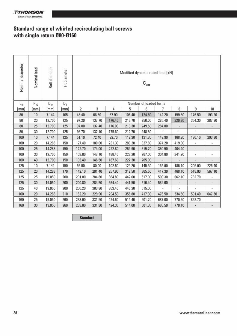
www.thomsonlinear.com38
Standard range of whirled recirculating ball screws with single return Ø80-Ø160
Nom
inal
dia
met
er
Nom
inal
lead
Ball
diam
eter
Fit d
iam
eter Modified dynamic rated load [kN]
Cam
Modified static rated load [kN]
C0am
d0 Ph0 Dw D1 Number of loaded turns Number of loaded turns[mm] [mm] [mm] [mm] 2 3 4 5 6 7 8 9 10 2 3 4 5 6 7 8 9 10
80 10 7 .144 105 48 .40 68 .60 87 .90 106 .40 124 .50 142 .20 159 .50 176 .50 193 .20 129 .00 193 .50 258 .00 322 .50 387 .00 451 .50 516 .00 580 .50 645 .0080 20 12 .700 125 97 .20 137 .70 176 .40 213 .70 250 .00 285 .40 320 .20 354 .30 387 .90 198 .40 297 .50 396 .70 495 .90 595 .10 694 .30 793 .40 892 .60 991 .8080 25 12 .700 125 97 .00 137 .40 176 .00 213 .30 249 .50 284 .80 - - - 198 .00 297 .10 396 .10 495 .10 594 .10 693 .10 - - -80 30 12 .700 125 96 .70 137 .10 175 .60 212 .70 248 .80 - - - - 197 .60 296 .50 395 .30 494 .10 592 .90 - - - -100 10 7 .144 125 51 .10 72 .40 92 .70 112 .30 131 .30 149 .90 168 .20 186 .10 203 .80 162 .30 243 .50 324 .70 405 .80 487 .00 568 .20 649 .30 730 .50 811 .70100 20 14 .288 150 127 .40 180 .60 231 .30 280 .20 327 .80 374 .20 419 .80 - - 300 .20 450 .30 600 .40 750 .50 900 .60 1050 .70 1200 .80 - -100 25 14 .288 150 122 .70 174 .00 222 .80 269 .90 315 .70 360 .50 404 .40 - - 284 .10 426 .10 568 .20 710 .20 852 .30 994 .30 1136 .40 - -100 30 12 .700 150 103 .80 147 .10 188 .40 228 .20 267 .00 304 .80 341 .90 - - 250 .50 375 .70 501 .00 626 .20 751 .50 876 .70 1002 .00 - -100 40 12 .700 150 103 .40 146 .50 187 .60 227 .30 265 .90 - - - - 249 .70 374 .50 499 .40 624 .20 749 .00 - - - -125 10 7 .144 150 56 .50 80 .00 102 .50 124 .20 145 .30 165 .90 186 .10 205 .90 225 .40 208 .10 312 .10 416 .20 520 .20 624 .20 728 .30 832 .30 936 .40 1040 .40125 20 14 .288 170 142 .10 201 .40 257 .90 312 .50 365 .50 417 .30 468 .10 518 .00 567 .10 383 .40 575 .10 766 .80 958 .50 1150 .20 1341 .90 1533 .60 1725 .30 1917 .00125 25 19 .050 200 201 .00 284 .80 364 .80 442 .00 517 .00 590 .30 662 .10 732 .70 - 322 .70 484 .10 645 .40 806 .80 968 .10 1129 .50 1290 .80 1452 .20 -125 30 19 .050 200 200 .80 284 .50 364 .40 441 .50 516 .40 589 .60 - - - 322 .40 483 .70 644 .90 806 .10 967 .30 1128 .60 - - -125 40 19 .050 200 200 .20 283 .80 363 .40 440 .30 515 .00 - - - - 321 .80 482 .70 643 .50 804 .40 965 .30 - - - -160 20 14 .288 210 162 .20 229 .90 294 .50 356 .80 417 .30 476 .50 534 .50 591 .40 647 .50 516 .10 774 .10 1032 .10 1290 .20 1548 .20 1806 .20 2064 .20 2322 .30 2580 .30160 25 19 .050 260 233 .90 331 .50 424 .60 514 .40 601 .70 687 .00 770 .60 852 .70 - 442 .20 663 .30 884 .40 1105 .60 1326 .70 1547 .80 1768 .90 1990 .00 -160 30 19 .050 260 233 .80 331 .30 424 .30 514 .00 601 .30 686 .50 770 .10 - - 442 .00 663 .00 884 .00 1105 .00 1326 .00 1547 .00 1768 .00 - -
Standard
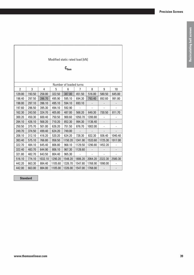
www.thomsonlinear.com 39
Precision Screws
Reci
rcul
atin
g ba
ll sc
rew
s
Nom
inal
dia
met
er
Nom
inal
lead
Ball
diam
eter
Fit d
iam
eter Modified dynamic rated load [kN]
Cam
Modified static rated load [kN]
C0am
d0 Ph0 Dw D1 Number of loaded turns Number of loaded turns[mm] [mm] [mm] [mm] 2 3 4 5 6 7 8 9 10 2 3 4 5 6 7 8 9 10
80 10 7 .144 105 48 .40 68 .60 87 .90 106 .40 124 .50 142 .20 159 .50 176 .50 193 .20 129 .00 193 .50 258 .00 322 .50 387 .00 451 .50 516 .00 580 .50 645 .0080 20 12 .700 125 97 .20 137 .70 176 .40 213 .70 250 .00 285 .40 320 .20 354 .30 387 .90 198 .40 297 .50 396 .70 495 .90 595 .10 694 .30 793 .40 892 .60 991 .8080 25 12 .700 125 97 .00 137 .40 176 .00 213 .30 249 .50 284 .80 - - - 198 .00 297 .10 396 .10 495 .10 594 .10 693 .10 - - -80 30 12 .700 125 96 .70 137 .10 175 .60 212 .70 248 .80 - - - - 197 .60 296 .50 395 .30 494 .10 592 .90 - - - -100 10 7 .144 125 51 .10 72 .40 92 .70 112 .30 131 .30 149 .90 168 .20 186 .10 203 .80 162 .30 243 .50 324 .70 405 .80 487 .00 568 .20 649 .30 730 .50 811 .70100 20 14 .288 150 127 .40 180 .60 231 .30 280 .20 327 .80 374 .20 419 .80 - - 300 .20 450 .30 600 .40 750 .50 900 .60 1050 .70 1200 .80 - -100 25 14 .288 150 122 .70 174 .00 222 .80 269 .90 315 .70 360 .50 404 .40 - - 284 .10 426 .10 568 .20 710 .20 852 .30 994 .30 1136 .40 - -100 30 12 .700 150 103 .80 147 .10 188 .40 228 .20 267 .00 304 .80 341 .90 - - 250 .50 375 .70 501 .00 626 .20 751 .50 876 .70 1002 .00 - -100 40 12 .700 150 103 .40 146 .50 187 .60 227 .30 265 .90 - - - - 249 .70 374 .50 499 .40 624 .20 749 .00 - - - -125 10 7 .144 150 56 .50 80 .00 102 .50 124 .20 145 .30 165 .90 186 .10 205 .90 225 .40 208 .10 312 .10 416 .20 520 .20 624 .20 728 .30 832 .30 936 .40 1040 .40125 20 14 .288 170 142 .10 201 .40 257 .90 312 .50 365 .50 417 .30 468 .10 518 .00 567 .10 383 .40 575 .10 766 .80 958 .50 1150 .20 1341 .90 1533 .60 1725 .30 1917 .00125 25 19 .050 200 201 .00 284 .80 364 .80 442 .00 517 .00 590 .30 662 .10 732 .70 - 322 .70 484 .10 645 .40 806 .80 968 .10 1129 .50 1290 .80 1452 .20 -125 30 19 .050 200 200 .80 284 .50 364 .40 441 .50 516 .40 589 .60 - - - 322 .40 483 .70 644 .90 806 .10 967 .30 1128 .60 - - -125 40 19 .050 200 200 .20 283 .80 363 .40 440 .30 515 .00 - - - - 321 .80 482 .70 643 .50 804 .40 965 .30 - - - -160 20 14 .288 210 162 .20 229 .90 294 .50 356 .80 417 .30 476 .50 534 .50 591 .40 647 .50 516 .10 774 .10 1032 .10 1290 .20 1548 .20 1806 .20 2064 .20 2322 .30 2580 .30160 25 19 .050 260 233 .90 331 .50 424 .60 514 .40 601 .70 687 .00 770 .60 852 .70 - 442 .20 663 .30 884 .40 1105 .60 1326 .70 1547 .80 1768 .90 1990 .00 -160 30 19 .050 260 233 .80 331 .30 424 .30 514 .00 601 .30 686 .50 770 .10 - - 442 .00 663 .00 884 .00 1105 .00 1326 .00 1547 .00 1768 .00 - -
Standard
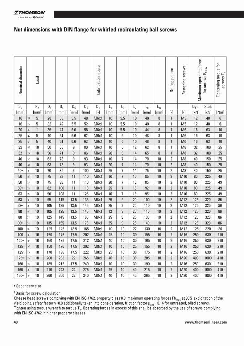
www.thomsonlinear.com40
Nut dimensions with DIN flange for whirled recirculating ball screws
Nom
inal
dia
met
er
Lead
Lubr
icat
ion
nipp
le
Drill
ing
patte
rn
Fast
enin
g sc
rew
s
Max
imum
ope
ratin
g fo
rce
fo
r scr
ews
F bm
ax
Tigh
teni
ng to
rque
for
scre
ws
T a
d0 Ph D1 D4 D5 D6 DB L1 L3 L7 L8 L10 Dyn . Stat .[mm] [mm] [mm] [mm] [mm] [mm] [-] [mm] [mm] [mm] [mm] [mm] [-] [-] [kN] [kN] [Nm]
16 a 5 28 38 5 .5 48 M6x1 10 5 .5 10 40 8 1 M5 12 40 616 > 5 32 42 5 .5 52 M6x1 10 5 .5 10 40 8 1 M5 12 40 620 > 1 36 47 6 .6 58 M6x1 10 5 .5 10 44 8 1 M6 16 63 1025 a 5 40 51 6 .6 62 M6x1 10 6 10 48 8 1 M6 16 63 1025 > 5 40 51 6 .6 62 M6x1 10 6 10 48 8 1 M6 16 63 1032 a 10 50 65 9 80 M6x1 10 6 12 62 8 1 M8 32 100 2532 > 10 56 71 9 86 M6x1 20 6 14 65 8 1 M8 32 100 2540 < 10 63 78 9 93 M8x1 10 7 14 70 10 2 M8 40 150 2540 A 10 63 78 9 93 M8x1 20 7 14 70 10 2 M8 40 150 2540• > 10 70 85 9 100 M8x1 25 7 14 75 10 2 M8 40 150 2550 a 10 75 93 11 110 M8x1 10 7 16 85 10 2 M10 80 225 4950 > 10 75 93 11 110 M8x1 20 7 16 85 10 2 M10 80 225 4950• > 10 82 100 11 118 M8x1 25 7 16 92 10 2 M10 80 225 4963 a 10 90 108 11 125 M8x1 10 7 18 95 10 2 M10 80 225 4963 > 10 95 115 13 .5 135 M8x1 25 9 20 100 10 2 M12 125 320 8663• > 10 105 125 13 .5 145 M8x1 25 9 20 110 10 2 M12 125 320 8680 a 10 105 125 13 .5 145 M8x1 12 9 20 110 10 2 M12 125 320 8680 > 10 125 145 13 .5 165 M8x1 25 9 25 130 10 2 M12 125 320 8680• > 10 135 155 13 .5 175 M8x1 25 9 25 140 10 2 M12 125 320 86100 a 10 125 145 13 .5 165 M8x1 10 10 22 130 10 2 M12 125 320 86100 > 10 150 176 17 .5 202 M8x1 25 10 30 155 10 2 M16 250 630 210100• > 10 160 186 17 .5 212 M8x1 40 10 30 165 10 2 M16 250 630 210125 a 10 150 176 17 .5 202 M8x1 10 10 25 155 10 2 M16 250 630 210125 > 10 170 196 17 .5 222 M8x1 25 10 30 175 10 2 M16 250 630 210125• > 10 200 233 22 265 M8x1 40 10 30 205 10 2 M20 400 1000 410160 a 10 185 212 17 .5 240 M8x1 10 10 30 190 10 2 M16 250 630 210160 > 10 210 243 22 275 M8x1 25 10 40 215 10 2 M20 400 1000 410160• > 10 260 300 22 340 M8x1 40 10 40 265 10 2 M20 400 1000 410
• Secondary size1 Basis for screw calculation: Cheese head screws complying with EN ISO 4762, property class 8 .8, maximum operating forces Fbmax at 90% exploitation of the yield point, safety factor v=0 .8 additionally taken into consideration, friction factor µges= 0 .14 for untreated, oiled screws .Tighten using torque wrench to torque Ta . Operating forces in excess of this shall be absorbed by the use of screws complying with EN ISO 4762 in higher property classes

www.thomsonlinear.com 41
Precision Screws
Reci
rcul
atin
g ba
ll sc
rew
s
Standard range for whirled heavy duty recirculating ball screwsOnly available with single nuts with backlash (SEM)
Drilling pattern 1
d0 Ph Dw D1 i L Cam C0am D4 D5 D6 DB L1 L3 L7 L8 L10
[mm] [mm] [mm] [mm] [each] [mm] [kN] [kN] [mm] [mm] [mm] [mm] [mm] [mm] [mm] [mm] [mm]40 12 7 .938 75 8 165 .0 220 434 93 11 110 M8x1 25 7 16 85 1050 20 9 .525 90 5 .8 152 .0 259 .4 603 .4 108 11 125 M8x1 25 7 20 95 1050 25 9 .525 90 5 .8 177 .5 258 600 .9 108 11 125 M8x1 25 7 20 95 1063 20 12 .700 105 8 249 .0 478 .6 1108 .7 125 13 .5 145 M8x1 25 9 25 110 1063 25 12 .700 120 5 .8 185 .5 419 .8 1002 .2 145 13 .5 165 M8x1 30 9 25 130 1080 20 14 .288 135 9 280 .5 690 .2 1860 .8 155 13 .5 175 M8x1 30 9 30 140 1080 25 14 .288 135 7 273 .0 554 .8 1445 155 13 .5 175 M8x1 30 9 30 140 10
100 20 14 .288 160 8 252 .0 709 .3 2276 .5 186 17 .5 212 M8x1 40 10 30 165 10100 25 19 .050 160 8 310 .0 968 .4 1843 .8 189 17 .5 212 M8x1 40 10 30 165 10125 20 14 .288 200 11 338 .0 1040 .1 3997 .8 233 22 265 M8x1 40 10 40 205 10125 25 19 .050 200 9 349 .0 1238 2753 .2 233 22 265 M8x1 40 10 40 205 10125 30 19 .050 200 7 330 .5 996 .3 2139 .6 233 22 265 M8x1 40 10 40 205 10160 20 14 .288 260 12 357 .0 1279 .9 5870 .3 300 22 340 M8x1 40 10 45 265 10160 25 19 .050 260 9 354 .0 1440 .8 3772 .8 300 22 340 M8x1 40 10 45 265 10160 30 19 .050 260 8 370 .5 1301 .2 3351 .9 300 22 340 M8x1 40 10 45 265 10
Dimensions do not comply with DIN
Have you not found the correct size?Should you have any further questions, please contact our engineers
Drilling pattern 2
B
Wiper
1

www.thomsonlinear.com42
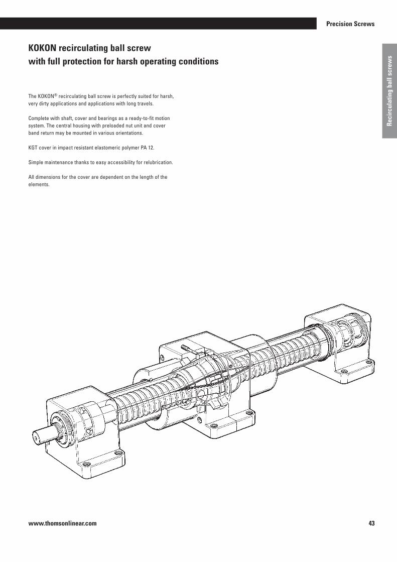
www.thomsonlinear.com 43
Precision Screws
Reci
rcul
atin
g ba
ll sc
rew
s
KOKON recirculating ball screw with full protection for harsh operating conditions
The KOKON® recirculating ball screw is perfectly suited for harsh, very dirty applications and applications with long travels .
Complete with shaft, cover and bearings as a ready-to-fit motion system . The central housing with preloaded nut unit and cover band return may be mounted in various orientations .
KGT cover in impact resistant elastomeric polymer PA 12 .
Simple maintenance thanks to easy accessibility for relubrication .
All dimensions for the cover are dependent on the length of the elements .

www.thomsonlinear.com44
KOKON® Fully protected recirculating ball screw
Technical data KOKON 4005 KOKON 4010■ Travel speed: max . 250 mm/s max . 500 mm/s■ Repetition accuracy: ± 0 .05 mm ± 0 .05 mm■ Acceleration: max . 20 m/s2 max . 20 m/s2
■ Speed [rpm]: max . 3000 max . 3000■ Diameter: 40 mm 40 mm■ Motion system element: Preloaded recirculating ball screw■ Lead: 5 mm 10 mm■ Drag torque M0: 0 .6 ± 0 .2 Nm 1 .6 ± 0 .4 Nm■ Axial load capacity C0: 46000 N 46000 N Axial load capacity C1): 23000 N 42000 N Axial load capacity C2): 23000 N 38000 N■ Efficiency η: 0 .75 0 .75■ Weights Base without lift: 4 .40 kg 4 .40 kg 100 mm lift: 0 .95 kg 0 .95 kg Nut unit with housing: 3 .60 kg 3 .60 kg
Material characteristics Cover band■ Cover band PA12 PA12■ Modulus of elasticity 300 N/mm2 300 N/mm2
■ Tear resistance 40 N/mm2 40 N/mm2
■ Shore hardness 54 54■ Water absorption max . 1 .4 % max . 1 .4 %■ Oil and coolant resistant yes yes
1) DIN 69051 Draft April 19782) DIN 69051 Draft May 1989
See p . 54 et seq . for calculation principles
Motor housing accessories
( )
Fixed bearing Mounting holeseach 4xM12
Loose bearing
Mating dimensions fixed bearing = loose bearing

www.thomsonlinear.com 45
Precision Screws
Reci
rcul
atin
g ba
ll sc
rew
s
Notes
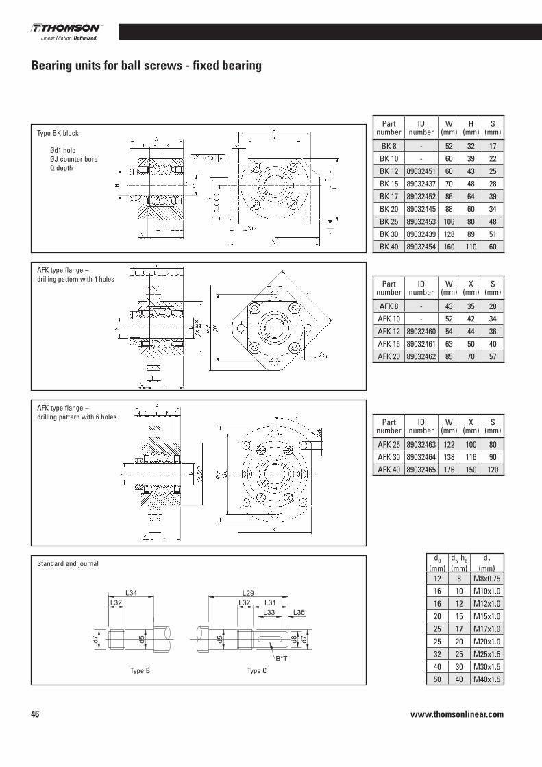
www.thomsonlinear.com46
Bearing units for ball screws - fixed bearing
Type BK block
AFK type flange – drilling pattern with 4 holes
AFK type flange – drilling pattern with 6 holes
Standard end journal
Type B Type C
Ød1 holeØJ counter boreQ depth
Dimensions Technical data
Part number
IDnumber
W(mm)
H(mm)
S(mm)
R(mm)
T(mm)
X(mm)
K(mm)
d1(mm)
d3(mm)
J(mm)
Q(mm)
M(mm)
L(mm)
A(mm)
E(mm)
F(mm)
V(mm)
Bearing type
Rated axial load (kN)
Maximum permissible
load (kN)BK 8 - 52 32 17 18 .5 26 38 25 6 .6 8 11 6 .5 M8x0 .75 23 33 11 .5 5 EN8 1 .64 1 .48BK 10 - 60 39 22 26 30 46 34 6 .6 10 11 6 .5 M10x1 .0 25 38 6 13 6 7000A 6 .70 2 .78BK 12 89032451 60 43 25 30 30 46 34 6 .6 12 11 6 .5 M12x1 .0 25 38 6 13 6 7001A 7 .25 3 .10BK 15 89032437 70 48 28 33 35 54 40 6 .6 15 11 6 .5 M15x1 .0 27 40 6 15 7 7002A 7 .75 4 .07BK 17 89032452 86 64 39 46 43 68 50 9 17 14 8 .5 M17x1 .0 35 52 8 19 9 7203A 14 .00 5 .95BK 20 89032445 88 60 34 42 44 70 52 9 20 14 8 .5 M20x1 .0 35 52 8 19 9 7004A 12 .95 9 .70BK 25 89032453 106 80 48 59 53 85 64 11 25 17 .5 11 M25x1 .5 42 62 10 22 11 7205A 20 .60 11 .70BK 30 89032439 128 89 51 63 64 102 76 14 30 20 13 M30x1 .5 45 66 11 23 12 7206B 28 .60 16 .60BK 40 89032454 160 110 60 80 80 130 100 18 40 26 17 .5 M40x1 .5 61 82 14 33 14 7208B 45 .00 27 .70
Dimensions Technical data
Part number
IDnumber
W(mm)
X(mm)
S(mm)
K(mm)
L(mm)
A(mm)
E(mm)
V(mm)
d1(mm)
d3(mm)
P(°)
M(mm)
Bearing type
Rated axial load (kN)
Maximum permissible
load (kN)AFK 8 - 43 35 28 35 21 30 7 5 3 .4 8 90 M8x0 .75 608 1 .64 3 .35AFK 10 - 52 42 34 42 25 38 7 6 4 .5 10 90 M10x1 .0 7000A 6 .70 2 .78AFK 12 89032460 54 44 36 44 25 38 8 6 4 .5 12 90 M12x1 .0 7001A 7 .25 3 .10AFK 15 89032461 63 50 40 52 27 40 10 7 5 .5 15 90 M15x1 .0 7002A 7 .75 4 .07AFK 20 89032462 85 70 57 68 37 52 15 7 6 .6 20 90 M20x1 .0 7204B 18 .30 9 .70
Dimensions Technical data
Part number
IDnumber
W(mm)
X(mm)
S(mm)
K(mm)
L(mm)
A(mm)
E(mm)
V(mm)
d1(mm)
d3(mm)
P(°)
M(mm)
Bearing type
Rated axial load (kN)
Maximum permissible
load (kN)AFK 25 89032463 122 100 80 92 42 62 15 11 11 25 45 M25x1 .5 7205B 20 .60 11 .70AFK 30 89032464 138 116 90 106 45 66 16 12 11 30 45 M30x1 .5 7206B 28 .60 16 .60AFK 40 89032465 176 150 120 128 61 82 19 15 14 40 45 M40x1 .5 7208B 45 .00 27 .70
Dimensionsd0
(mm)d5 h6(mm)
d7(mm)
d8 h7(mm)
L29(mm)
L31(mm)
L32(mm)
L34(mm)
B P9(mm)
T(mm)
L33(mm)
L35(mm)
Note
12 8 M8x0 .75 6 47/45 15 8 32/30 2 2 .2 10 2 .5 BK/AFK16 10 M10x1 .0 8 58 20 10 38 3 1 .8 15 2 .516 12 M12x1 .0 10 63 25 10 38 3 1 .8 18 3 .520 15 M15x1 .0 14 77 35 12 42 4 2 .5 27 425 17 M17x1 .0 15 94 40 14 54 5 3 32 4 .5 BK only25 20 M20x1 .0 16 99 45 14 54 5 3 36 4 .532 25 M25x1 .5 20 120 55 17 65 6 3 .5 45 540 30 M30x1 .5 25 133 64 17 69 8 4 50 750 40 M40x1 .5 36 165 78 21 87 10 5 63 7 .5

www.thomsonlinear.com 47
Precision Screws
Reci
rcul
atin
g ba
ll sc
rew
s
Dimensions Technical data
Part number
IDnumber
W(mm)
H(mm)
S(mm)
R(mm)
T(mm)
X(mm)
K(mm)
d1(mm)
d3(mm)
J(mm)
Q(mm)
M(mm)
L(mm)
A(mm)
E(mm)
F(mm)
V(mm)
Bearing type
Rated axial load (kN)
Maximum permissible
load (kN)BK 8 - 52 32 17 18 .5 26 38 25 6 .6 8 11 6 .5 M8x0 .75 23 33 11 .5 5 EN8 1 .64 1 .48BK 10 - 60 39 22 26 30 46 34 6 .6 10 11 6 .5 M10x1 .0 25 38 6 13 6 7000A 6 .70 2 .78BK 12 89032451 60 43 25 30 30 46 34 6 .6 12 11 6 .5 M12x1 .0 25 38 6 13 6 7001A 7 .25 3 .10BK 15 89032437 70 48 28 33 35 54 40 6 .6 15 11 6 .5 M15x1 .0 27 40 6 15 7 7002A 7 .75 4 .07BK 17 89032452 86 64 39 46 43 68 50 9 17 14 8 .5 M17x1 .0 35 52 8 19 9 7203A 14 .00 5 .95BK 20 89032445 88 60 34 42 44 70 52 9 20 14 8 .5 M20x1 .0 35 52 8 19 9 7004A 12 .95 9 .70BK 25 89032453 106 80 48 59 53 85 64 11 25 17 .5 11 M25x1 .5 42 62 10 22 11 7205A 20 .60 11 .70BK 30 89032439 128 89 51 63 64 102 76 14 30 20 13 M30x1 .5 45 66 11 23 12 7206B 28 .60 16 .60BK 40 89032454 160 110 60 80 80 130 100 18 40 26 17 .5 M40x1 .5 61 82 14 33 14 7208B 45 .00 27 .70
Dimensions Technical data
Part number
IDnumber
W(mm)
X(mm)
S(mm)
K(mm)
L(mm)
A(mm)
E(mm)
V(mm)
d1(mm)
d3(mm)
P(°)
M(mm)
Bearing type
Rated axial load (kN)
Maximum permissible
load (kN)AFK 8 - 43 35 28 35 21 30 7 5 3 .4 8 90 M8x0 .75 608 1 .64 3 .35
AFK 10 - 52 42 34 42 25 38 7 6 4 .5 10 90 M10x1 .0 7000A 6 .70 2 .78AFK 12 89032460 54 44 36 44 25 38 8 6 4 .5 12 90 M12x1 .0 7001A 7 .25 3 .10AFK 15 89032461 63 50 40 52 27 40 10 7 5 .5 15 90 M15x1 .0 7002A 7 .75 4 .07AFK 20 89032462 85 70 57 68 37 52 15 7 6 .6 20 90 M20x1 .0 7204B 18 .30 9 .70
Dimensions Technical data
Part number
IDnumber
W(mm)
X(mm)
S(mm)
K(mm)
L(mm)
A(mm)
E(mm)
V(mm)
d1(mm)
d3(mm)
P(°)
M(mm)
Bearing type
Rated axial load (kN)
Maximum permissible
load (kN)AFK 25 89032463 122 100 80 92 42 62 15 11 11 25 45 M25x1 .5 7205B 20 .60 11 .70AFK 30 89032464 138 116 90 106 45 66 16 12 11 30 45 M30x1 .5 7206B 28 .60 16 .60AFK 40 89032465 176 150 120 128 61 82 19 15 14 40 45 M40x1 .5 7208B 45 .00 27 .70
Dimensionsd0
(mm)d5 h6(mm)
d7(mm)
d8 h7(mm)
L29(mm)
L31(mm)
L32(mm)
L34(mm)
B P9(mm)
T(mm)
L33(mm)
L35(mm)
Note
12 8 M8x0 .75 6 47/45 15 8 32/30 2 2 .2 10 2 .5 BK/AFK16 10 M10x1 .0 8 58 20 10 38 3 1 .8 15 2 .516 12 M12x1 .0 10 63 25 10 38 3 1 .8 18 3 .520 15 M15x1 .0 14 77 35 12 42 4 2 .5 27 425 17 M17x1 .0 15 94 40 14 54 5 3 32 4 .5 BK only25 20 M20x1 .0 16 99 45 14 54 5 3 36 4 .532 25 M25x1 .5 20 120 55 17 65 6 3 .5 45 540 30 M30x1 .5 25 133 64 17 69 8 4 50 750 40 M40x1 .5 36 165 78 21 87 10 5 63 7 .5
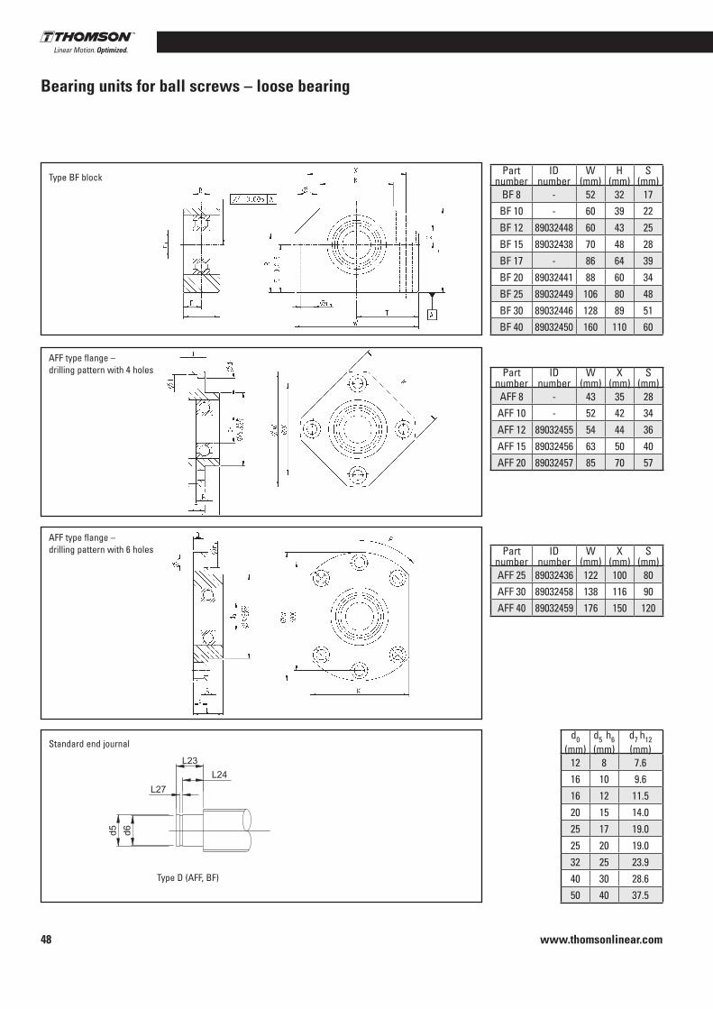
www.thomsonlinear.com48
Bearing units for ball screws – loose bearing
Type BF block
AFF type flange – drilling pattern with 4 holes
AFF type flange – drilling pattern with 6 holes
Standard end journal
Type D (AFF, BF)
Dimensions Technical dataPart
numberID
numberW
(mm)H
(mm)S
(mm)R
(mm)T
(mm)X
(mm)K
(mm)d1
(mm)d3
(mm)J
(mm)Q
(mm)L
(mm)E
(mm)Bearing
typeRated radial
load (kN)BF 8 - 52 32 17 18 .5 26 38 25 6 .6 6 11 6 .5 20 10 606 2 .31BF 10 - 60 39 22 26 30 46 34 6 .6 8 11 6 .5 20 10 608 3 .35BF 12 89032448 60 43 25 35 30 46 35 6 .6 10 11 6 .5 20 10 6000 4 .65BF 15 89032438 70 48 28 38 35 54 40 6 .6 15 11 6 .5 20 10 6002 5 .70BF 17 - 86 64 39 46 43 68 50 9 17 14 8 .5 23 11 .5 6203 9 .75BF 20 89032441 88 60 34 50 44 70 52 9 20 14 8 .5 26 13 6004 9 .55BF 25 89032449 106 80 48 70 53 85 64 11 25 17 .5 11 30 15 6205 14 .30BF 30 89032446 128 89 51 78 64 102 76 14 30 20 13 32 16 6206 19 .80BF 40 89032450 160 110 60 90 80 130 100 18 40 26 17 .5 37 18 .5 6208 29 .70
Dimensions Technical dataPart
numberID
numberW
(mm)X
(mm)S
(mm)K
(mm)L
(mm)E
(mm)N
(mm)d1
(mm)d3
(mm)J
(mm)Q
(mm)P(°)
Bearing type
Rated radialload (kN)
AFF 8 - 43 35 28 35 11 6 4 3 .4 6 6 .5 4 90 606 2 .31AFF 10 - 52 42 34 42 12 7 4 4 .5 8 8 5 90 608 3 .35AFF 12 89032455 54 44 36 44 15 8 4 4 .5 10 8 5 90 6000 4 .65AFF 15 89032456 63 50 40 52 17 9 4 5 .5 15 9 .5 6 90 6002 5 .70AFF 20 89032457 85 70 57 68 20 14 4 6 .6 20 11 10 90 6204 13 .00
Dimensions Technical dataPart
numberID
numberW
(mm)X
(mm)S
(mm)K
(mm)L
(mm)E
(mm)N
(mm)d1
(mm)d3
(mm)J
(mm)Q
(mm)P(°)
Bearing type
Rated radialload (kN)
AFF 25 89032436 122 100 80 92 30 15 6 11 25 17 .5 11 45 6205 14 .30AFF 30 89032458 138 116 90 106 32 15 6 11 30 17 .5 11 45 6206 19 .80AFF 40 89032459 176 150 120 128 36 18 6 14 40 20 13 45 6208 29 .70
Dimensionsd0
(mm)d5 h6(mm)
d7 h12(mm)
L23(mm)
L24(mm)
L27 H13(mm)
12 8 7 .6 7 .5 6 0 .916 10 9 .6 12 8 1 .116 12 11 .5 10 .5 8 1 .120 15 14 .0 13 9 1 .125 17 19 .0 16 12 1 .325 20 19 .0 16 12 1 .332 25 23 .9 19 15 1 .340 30 28 .6 21 16 1 .650 40 37 .5 25 18 1 .85
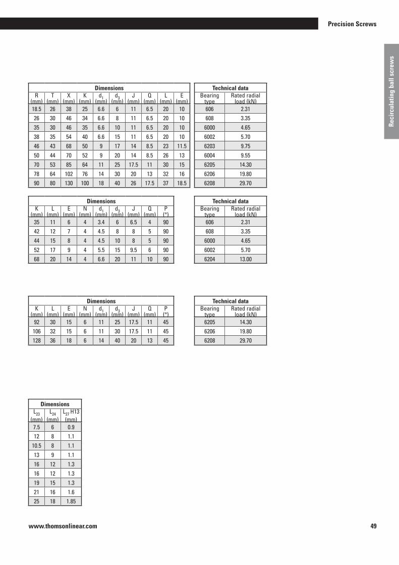
www.thomsonlinear.com 49
Precision Screws
Reci
rcul
atin
g ba
ll sc
rew
s
Dimensions Technical dataPart
numberID
numberW
(mm)H
(mm)S
(mm)R
(mm)T
(mm)X
(mm)K
(mm)d1
(mm)d3
(mm)J
(mm)Q
(mm)L
(mm)E
(mm)Bearing
typeRated radial
load (kN)BF 8 - 52 32 17 18 .5 26 38 25 6 .6 6 11 6 .5 20 10 606 2 .31
BF 10 - 60 39 22 26 30 46 34 6 .6 8 11 6 .5 20 10 608 3 .35BF 12 89032448 60 43 25 35 30 46 35 6 .6 10 11 6 .5 20 10 6000 4 .65BF 15 89032438 70 48 28 38 35 54 40 6 .6 15 11 6 .5 20 10 6002 5 .70BF 17 - 86 64 39 46 43 68 50 9 17 14 8 .5 23 11 .5 6203 9 .75BF 20 89032441 88 60 34 50 44 70 52 9 20 14 8 .5 26 13 6004 9 .55BF 25 89032449 106 80 48 70 53 85 64 11 25 17 .5 11 30 15 6205 14 .30BF 30 89032446 128 89 51 78 64 102 76 14 30 20 13 32 16 6206 19 .80BF 40 89032450 160 110 60 90 80 130 100 18 40 26 17 .5 37 18 .5 6208 29 .70
Dimensions Technical dataPart
numberID
numberW
(mm)X
(mm)S
(mm)K
(mm)L
(mm)E
(mm)N
(mm)d1
(mm)d3
(mm)J
(mm)Q
(mm)P(°)
Bearing type
Rated radialload (kN)
AFF 8 - 43 35 28 35 11 6 4 3 .4 6 6 .5 4 90 606 2 .31AFF 10 - 52 42 34 42 12 7 4 4 .5 8 8 5 90 608 3 .35AFF 12 89032455 54 44 36 44 15 8 4 4 .5 10 8 5 90 6000 4 .65AFF 15 89032456 63 50 40 52 17 9 4 5 .5 15 9 .5 6 90 6002 5 .70AFF 20 89032457 85 70 57 68 20 14 4 6 .6 20 11 10 90 6204 13 .00
Dimensions Technical dataPart
numberID
numberW
(mm)X
(mm)S
(mm)K
(mm)L
(mm)E
(mm)N
(mm)d1
(mm)d3
(mm)J
(mm)Q
(mm)P(°)
Bearing type
Rated radialload (kN)
AFF 25 89032436 122 100 80 92 30 15 6 11 25 17 .5 11 45 6205 14 .30AFF 30 89032458 138 116 90 106 32 15 6 11 30 17 .5 11 45 6206 19 .80AFF 40 89032459 176 150 120 128 36 18 6 14 40 20 13 45 6208 29 .70
Dimensionsd0
(mm)d5 h6(mm)
d7 h12(mm)
L23(mm)
L24(mm)
L27 H13(mm)
12 8 7 .6 7 .5 6 0 .916 10 9 .6 12 8 1 .116 12 11 .5 10 .5 8 1 .120 15 14 .0 13 9 1 .125 17 19 .0 16 12 1 .325 20 19 .0 16 12 1 .332 25 23 .9 19 15 1 .340 30 28 .6 21 16 1 .650 40 37 .5 25 18 1 .85

www.thomsonlinear.com50
KON adapter support
Adapter support for radial fixing of KGF ball screw flanged nut .
Material: 1 .0065 (St37) or 1 .0507 (St52) .
Drilling pattern 1 in accordance with DIN 69051
Drilling pattern 2 in accordance with DIN 69051
Dimensions [mm] For KGF Drilling pattern A1 A2 max
1) A2 min B1 B2 C1 C2 C41) D1 D4 Th x D
KON 1605 4 60 35 25 50 34 40 24 M 8x15 28 38 M 5x10KON 1605/1610 1 60 35 25 50 34 40 24 M 8x15 28 38 M 5x10
KON 2005 4 68 37 .5 29 58 39 40 24 M 8x15 32 45 M 6x12KON 2005 1 68 37 .5 30 58 39 40 24 M 8x15 36 47 M 6x12
KON 2020/2050 4 75 42 .5 32 .5 65 49 40 24 M 10x15 35 50 M 6x12
KON 2505 4 75 42 .5 32 .5 65 49 40 24 M 10x15 38 50 M 6x12
KON 2505/2510/2520/2525/2550 1 75 42 .5 32 .5 65 49 40 24 M 10x12 40 51 M 6x12
KON 3205 4 82 45 37 75 54 50 30 M 10x12 45 58 M 6x12KON 3205/3232 1 92 50 40 85 60 50 30 M 12x15 50 65 M 8x12
KON 3210/3240/4005 4 92 50 42 85 60 50 30 M 12x15 53 68 M 6x12KON 3210/3220 1 92 50 40 85 60 50 30 M 12x15 53 65 M 8x12
KON 4010 4 120 70 50 100 76 65 41 M 14x25 63 78 M 8x14
KON 4005/4010/4020/4040 2 120 70 50 100 76 65 41 M 14x25 63 78 M 8x14
KON 5010 4 135 77 .5 57 .5 115 91 88 64 M 16x25 72 90 M 10x16KON 5010 2 135 77 .5 57 .5 115 91 88 64 M 16x25 75 93 M 10x16KON 5020 2 152 87 .5 65 130 101 88 64 M 16x30 85 103 M 10x16
KON 6310 4 152 87 .5 65 130 101 88 64 M 16x30 85 105 M 10x16KON 6320 2 172 97 .5 75 150 121 88 64 M 16x30 95 115 M 12x18
KON 8010 4 172 97 .5 75 150 121 88 64 M 16x30 105 125 M 12x18
1) Standard = A2 max (as delivered)
Drilling pattern 4 THOMSON NEFF standard

www.thomsonlinear.com 51
Precision Screws
Reci
rcul
atin
g ba
ll sc
rew
s
KAR universal joint adapter
Universal joint adapter for universally mounting on KGF ball screw flanged nut .
Material: 1 .0065 (St37) or 1 .0507 (St52) .
Drilling pattern 1 in accordance with DIN 69051
Drilling pattern 2 in accordance with DIN 69051
Drilling pattern 4 THOMSON NEFF standard
Dimensions [mm] For KGF Drilling pattern A2 B1 B2 B3 C1 D1 D4 Th x D
KAR 1605 4 12 70 50 10 20 28 38 M 5x10KAR 1605/1610 1 12 70 50 10 20 28 38 M 5x10
KAR 2005 4 16 85 58 13 .5 25 32 45 M 6x12KAR 2005 1 16 85 58 13 .5 25 36 47 M 6x12
KAR 2020/2050 4 18 95 65 15 25 35 50 M 6x12
KAR 2505 4 18 95 65 15 25 38 50 M 6x12
KAR 2505/2510/2520/2525/2550 1 18 95 65 15 25 40 51 M 6x12
KAR 3205 4 20 110 75 17 .5 30 45 58 M 6x12KAR 3205/3232 1 25 125 85 20 30 50 65 M 8x12
KAR 3210/3240/4005 4 25 125 85 20 30 53 68 M 6x12KAR 3210/3220 1 25 125 85 20 30 53 65 M 8x12
KAR 4010 4 30 140 100 20 40 63 78 M 8x14KAR 4005/4010/4020/4040 2 30 140 100 20 40 63 78 M 8x14
KAR 5010 4 40 165 115 25 50 72 90 M 10x16KAR 5010 2 40 165 115 25 50 75 93 M 10x16KAR 5020 2 40 180 130 25 50 85 103 M 10x16
KAR 6310 4 40 180 130 25 50 85 105 M 10x16KAR 6320 2 50 200 150 25 60 95 115 M 12x18KAR 8010 4 50 200 150 25 60 105 125 M 10x16

www.thomsonlinear.com52
SF helical spring cover
Helical spring cover for protection against ambient influences .Suitable for horizontal and vertical installation .
Material: Hardened spring steel .
A centering sleeve is required on the mounting face of the nut where a helical spring cover is used .
Only available for KGF-D, KGF-N, KGM-D and KGM-N style nuts .
Table headings are nominal diameter x lead (e .g . 16x05) . Lift
1) L7v = L7 vertical installation2) L7h = L7 horizontal installation
For 16x05 16x10
For 25x05 25x25 25x10 25x50 25x10
For 20x05 20x20 20x50
For 32x05 32x40
For 32x05 32x40 (continued)
For 32x10 (32x20)
D3 = 22 mmD10 = 17 mmL6 = 6 mmL9 = 21 mm
DesignationD8/L7v
1)/L8
L7h
2)
D9
SF 25/100/20 60 35
SF 25/150/20 110 38
SF 25/200/20 160 40
SF 25/250/20 210 44
SF 25/300/30 240 43
SF 25/350/30 290 46
SF 25/400/30 340 49
SF 25/450/40 370 48
SF 25/500/40 420 51
D3 = 38 mmD10 = 33 mmL6 = 6 mmL9 = 26 mm
DesignationD8/L7v
1)/L8
L7h
2)
D9
SF 40/550/50 450 61
SF 40/650/50 550 65
SF 40/750/50 650 69
SF 40/450/60 330 55
SF 40/550/60 430 58
SF 40/650/60 530 62
SF 40/750/60 630 66
SF 40/900/60 780 70
SF 40/650/75 500 62
SF 40/750/75 600 66
SF 40/900/75 750 72
SF 40/1100/78 950 78
SF 40/1300/75 1150 84
SF 40/1500/75 – 90
SF 40/1000/100 800 66
SF 40/1200/100 1000 70
SF 40/1500/100 1300 78
SF 40/1800/100 1600 82
SF 40/1800/120 1560 82
SF 40/2000/120 1760 86
SF 40/2200/120 – 91
D3 = 44 (48) mmD10 = 35 (39) mmL6 = 8 mmL9 = 27 mm
DesignationD8/L7v
1)/L8
L7h
2)
D9
SF 50/150/30 90 63
SF 50/250/30 190 68
SF 50/250/50 150 62
SF 50/350/50 250 66
SF 50/450/50 350 70
SF 50/550/50 450 73
SF 50/550/60 430 68
SF 50/650/60 530 73
SF 50/750/60 630 76
SF 50/750/75 600 78
SF 50/900/75 750 84
SF 50/1100/75 950 90
SF 50/1100/100 900 77
SF 50/1300/100 1100 80
SF 50/1500/100 1300 87
SF 50/1800/100 – 94
SF 50/1700/120 1460 91
SF 50/1900/120 1660 97
SF 50/2100/120 1860 102
SF 50/2300/120 – 105
SF 50/2500/120 – 111
SF 50/2800/120 – 118
SF 50/2800/150 2500 119
SF 50/3000/150 – 124
SF 50/3000/180 2640 123
SF 50/3250/180 – 130
SF 50/3250/200 2650 128
SF 50/3500/200 – 134
D3 = 28 mmD10 = 26 mmL6 = 6 mmL9 = 21 mm
DesignationD8/L7v
1)/L8
L7h
2)
D9
SF 30/150/30 90 39
SF 30/250/30 190 44
SF 30/350/30 290 49
SF 30/450/40 370 53
SF 30/550/40 470 58
SF 30/650/50 550 55
SF 30/750/50 650 59
D3 = 26 mmD10 = 21 mmL6 = 6 mmL9 = 21 mm
DesignationD8/L7v
1)/L8
L7h
2)
D9
SF 30/150/30 90 39
SF 30/250/30 190 44
SF 30/350/30 290 49
SF 30/450/40 370 53
SF 30/550/40 470 58
SF 30/650/50 550 55
SF 30/750/50 650 59
D3 = 38 mmD10 = 33 mmL6 = 6 mmL9 = 26 mm
DesignationD8/L7v
1)/L8
L7h
2)
D9
SF 40/150/30 90 51
SF 40/250/30 190 56
SF 40/350/30 290 60
SF 40/450/40 370 64
SF 40/550/40 470 68
SF 40/350/50 250 55
SF 40/450/50 350 59

www.thomsonlinear.com 53
Precision Screws
Reci
rcul
atin
g ba
ll sc
rew
s
SF helical spring cover
1) L7v = L7 vertical installation2) L7h = L7 horizontal installation
For 40x05 40x40
For 40x10 40x20
For 50x10 (50x20)
For 63x10 63x20
D3 = 48 mmD10 = 42 mmL6 = 6 mmL9 = 26 mm
DesignationD8/L7v
1)/L8
L7h
2)
D9
SF 50/150/30 90 63
SF 50/250/30 190 68
SF 50/250/50 150 62
SF 50/350/50 250 66
SF 50/450/50 350 70
SF 50/550/50 450 73
SF 50/550/60 430 68
SF 50/650/60 530 73
SF 50/750/60 630 76
SF 50/750/75 600 78
SF 50/900/75 750 84
SF 50/1100/75 950 90
SF 50/1100/100 900 77
SF 50/1300/100 1100 80
SF 50/1500/100 1300 87
SF 50/1800/100 – 94
SF 50/1700/120 1460 91
SF 50/1900/120 1660 97
SF 50/2100/120 1860 102
SF 50/2300/120 – 105
SF 50/2500/120 – 111
SF 50/2800/120 – 118
SF 50/2800/150 2500 119
SF 50/3000/150 – 124
SF 50/3000/180 2640 123
SF 50/3250/180 – 130
SF 50/3250/200 2650 128
SF 50/3500/200 – 134
D3 = 53 mmD10 = 46 mmL6 = 10 mmL9 = 35 mm
DesignationD8/L7v
1)/L8
L7h
2)
D9
SF 55/150/30 90 68
SF 55/250/30 190 73
SF 55/250/50 150 66
SF 55/350/50 250 71
SF 55/450/50 350 74
SF 55/550/50 450 77
SF 55/550/60 430 75
SF 55/650/60 530 79
SF 55/750/60 630 83
SF 55/750/75 600 83
SF 55/900/75 750 89
SF 55/1100/75 950 94
SF 55/1100/100 900 88
SF 55/1300/100 1100 89
SF 55/1500/100 1300 94
SF 55/1800/100 – 102
SF 55/1700/120 1460 96
SF 55/1900/120 1660 103
SF 55/2100/120 1860 106
SF 55/2300/120 2060 110
SF 55/2500/120 – 117
SF 55/2800/120 – 119
SF 55/2800/150 2500 122
SF 55/3000/150 – 126
SF 55/3000/180 2640 127
SF 55/3250/180 – 130
D3 = 62 mmD10 = 56 mmL6 = 11 mmL9 = 39 mm
DesignationD8/L7v
1)/L8
L7h
2)
D9
SF 65/250/30 190 85
SF 65/250/50 150 76
SF 65/350/50 250 83
SF 65/450/50 350 88
SF 65/550/60 430 88
SF 65/650/60 530 92
SF 65/750/60 630 96
SF 65/750/75 600 93
SF 65/900/75 750 99
SF 65/1100/75 950 107
SF 65/1100/100 900 95
SF 65/1300/100 1100 100
SF 65/1500/100 1300 109
SF 65/1800/100 – 120
SF 65/1700/120 1460 106
SF 65/1900/120 1660 109
SF 65/2100/120 1860 113
SF 65/2300/120 2060 118
SF 65/2500/120 – 128
SF 65/2800/120 – 132
SF 65/2800/150 2500 133
SF 65/3000/150 – 139
SF 65/3000/180 2640 136
SF 65/3250/180 – 146
SF 65/3250/200 2850 140
D3 = 74 mmD10 = 66 mmL6 = 11 mmL9 = 49 mm
DesignationD8/L7v
1)/L8
L7h
2)
D9
SF 75/250/50 150 89
SF 75/350/50 250 94
SF 75/450/50 350 101
SF 75/550/60 430 100
SF 75/650/60 530 103
SF 75/750/60 630 109
SF 75/650/75 500 99
SF 75/750/75 600 104
SF 75/900/75 750 111
SF 75/1100/100 900 108
SF 75/1300/100 1100 114
SF 75/1500/100 1300 120
SF 75/1700/100 1500 126
SF 75/1500/120 1260 115
SF 75/1800/120 1560 125
SF 75/2000/120 1760 128
SF 75/2200/120 – 132
SF 75/2000/150 1700 135
SF 75/2400/150 2100 141
SF 75/2800/150 – 145
SF 75/2800/180 2440 142
SF 75/3000/180 – 148
SF 75/3250/180 – 156
SF 75/3250/200 2850 148
SF 75/3500/200 – 158

www.thomsonlinear.com54
3
1A
1B
2
4
Calculation
Buckling load Fc [N]
Fcp = 0 .8 . Fc . fc ≥ Fmax . [N] Fc = [N] Dw = ball diameter
d ≈ [mm] d3 ≈ d0 – Dw
Index p → permissible lc [mm]
d0 + d3
2
1 .017 . 105 . d4
lc2
Buckling load
Return system Single Overall
nl [min-1]
140 .000 100 .000 d0 [mm] d0 [mm]
1A
1B
2
3 4
Speeds
Critical speed ncr [min-1]
Limit speed nl [min-1]
ncrp = 0 .8 . ncr . fcr > nmax [min-1]
ncr = 1 .2 . 108 .
[min-1]
d ≈ [mm] d3 ≈ d0 – Dw [mm] Dw = ball diameter
index p → permissible
d0 + d3
2
d/cr
2

www.thomsonlinear.com 55
Precision Screws
Reci
rcul
atin
g ba
ll sc
rew
s
Calculation
Service life
Modified service life in revolutions nm = Equivalent speed Fm = Equivalent load Modified service life in hours Cam = Modified dyn . rated load [N] Rated load/service life calculation based on DIN 69 051/4
Installation tolerances
nm =
nS
i = 1ni ·
qi
100[min-1] Fm =
nS
i = 1Fmi
3
· · ni nm
qi
100( )1/3[N]
L10 = Cam Fm[ ]3
. 106
Lh10 = L10
nm . 60
)Fm =
nS
i = 1Fi
3
· · ni nm
qi
100(1/3
[N]
Installation
Application of force
Please contact us regarding radial forcesOptimum

www.thomsonlinear.com56
Example F
= 10 .000
= 0,19 → fl ≈ 0 .97 Cam 53 .900
tan j = 10
= 0,08 40 · p
j = 4 .55°
Practical efficiency after running in
Calculation
The theoretical level of efficiency is reduced by around 5% to make allowances for operating influences such as speed, temperature and lubrication . If the ratio of load F to dynamic rated load Cam is less than 0 .5, a further reduction is made based on the load factor fl (see table below) .
The resulting efficiency only applies to the ball screw . The figure assumes the ball screw is lubricated but has no wiper or shaft bearing .
If you are interested in special measures for improving efficiency, please contact us .
F fl Cam
0 .4 0 .99
0 .3 0 .98
0 .2 0 .97
0 .1 0 .96
F = Axial load
Cam = Dynamic rated load
fl = Load factor
j = Lead angle(phi)
η =
Theoretical efficiency
(êta)
ηp =
Practical efficiencyη’p
Ta =
Input torque [Nm]
Te =
Output torque [Nm] F . Ph0 T
a =
2000 . p . ηp
[Nm]
Friction angle r” (rhò)
r” = 0 .23° At tolerance class P and T1 – T3 r” = 0 .34° At tolerance class T5
Ph0
+ See tables of dimensionsd0
F · Ph0 · η’p Te = 2000 . p
[Nm]
tan j η =
tan (j - r”)
Ph0
where tan j = d0 .
p
Ph0
where tan j = d0 . p
tan (j - r”)η’ =
tan j
Theoretical efficiency (η) when converting torque into axial force is calculated as follows:
The theoretical efficiency (η’) when converting an axial force into a torque is calculated as follows:
Converting torque into an axial force requires an input torque of:
Converting an axial force into a torque produces an output torque of:
Efficiency and torquesEfficiency is affected by many operating influences as well as geometric data . This means that practical values may fluctuate in relation to the calculated values by ± 5% .
η = 0,08
tan(4,55° + 0,23°)η = 0 .957ηp = η · 0 .95 · fI
ηp = 0 .957 · 0 .95 · 0 .97ηp = 0 .88 ± 5%
Cam = 53,900 N
F = 10,000 N

www.thomsonlinear.com 57
Precision Screws
Reci
rcul
atin
g ba
ll sc
rew
s
Fixed bearing at one end Fixed bearing at both ends
A . ERs1 = [N/µm] l1 . 103
E = 21 . 104 N/mm2
l, l1, l2 [mm]
A . E lRs2 = . [N/µm] → l2 ≤ l/2 l2 . 103 l - l2
Rs2 min at l2 = l/2
Calculation
Stiffness RThe total stiffness Rtot of a ball screw is composed of the stiffness of the shaft Rs and the stiffness of the nut unit Rnu, ar .
Shaft stiffness depends on the type of bearing .
Reference values for shaft cross-sections
1 1 1 = + [N/µm] Rtot Rs Rnu, ar
d0 16 20 25 32 40 50 63 80
Ph0 5 5 5–25 5 10 5 10–40 10, 20 10, 20 10 20
A [mm2] 162 263 428 723 685 1155 1075 1705 2823 4650 4412

www.thomsonlinear.com58
Permissible travel variances
P Transport ball screwsPositioning ball screws TType Type
Acceptance conditions
l1 = Axial thread length lu = Useful travel le = Overrun = Tab . 2 l0 = Nominal distance D l0 = Travel deviation
P1 – 3 P5 t
v300 p Permissible travel variance over 300 mm Tab . 1 Tab . 1 Tab . 1
v2p p Permissible travel variance over 2 ptravel Tab . 1 Tab . 1 –
c Travel compensation -0 .01/1000 0 0
ep Limit deviations for useful distance lu Tab . 3 Tab . 3
vup Permissible travel variance over useful travel lu Tab . 3 Tab . 3 –
lu ± . V300p 300
Tab. 1 Tolerance class
1 3 4 5 7
v300p [µm] 6 12 18 23 52
v2pp [µm] 4 6 7 8 12
Tab. 2
Nominal lead Ph [mm] a 2 .5 a 5 a 10 a 20 > 20
Lead error le [mm] 10 20 40 60 100
Tab. 3 lu [mm]
> 0 315 400 500 630 800 1000 1250 1600 2000 2500 3150 4000 5000 6300 8000 10000 12500
a 315 400 500 630 800 1000 1250 1600 2000 2500 3150 4000 5000 6300 8000 10000 12500 16000
Tole
ranc
e cl
ass
1ep
[µm
]
6 7 8 9 10 11 13 15 18 22 26 32 39 48 60 76 94 115
vup 6 6 7 7 8 9 10 11 13 15 17 21 27 33 40 50 61 76
3ep 12 13 15 16 18 21 24 29 35 41 50 62 76 92 115 140 175 220
vup 12 12 13 14 16 17 19 22 25 29 34 41 49 61 75 92 113 140
4ep 18 18 20 22 25 28 33 39 46 55 68 84 102 125 159 199 240 290
vup 18 19 20 21 23 26 29 33 38 44 52 56 68 83 101 124 152 189
5ep 23 25 27 32 36 40 47 55 65 78 96 115 140 170 210 270 330 410
vup 23 25 26 29 31 34 39 44 51 59 69 82 99 119 142 174 213 265
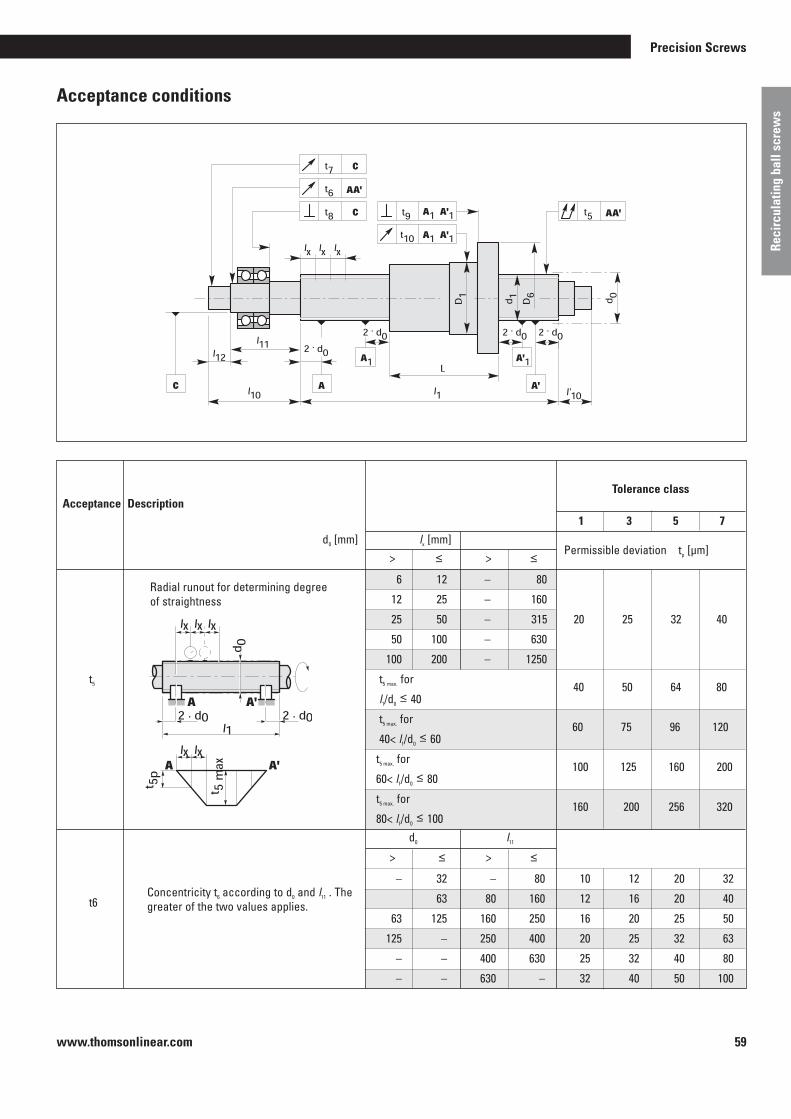
www.thomsonlinear.com 59
Precision Screws
Reci
rcul
atin
g ba
ll sc
rew
s
Acceptance conditions
Tolerance class Acceptance Description
1 3 5 7
d0 [mm] lx [mm] > ≤ > ≤
Permissible deviation tp [µm]
6 12 – 80
12 25 – 160
25 50 – 315 20 25 32 40
50 100 – 630
100 200 – 1250
t5 t5 max . for
l1/d0 ≤ 40 40 50 64 80
t5 max . for
40< l1/d0 ≤ 60 60 75 96 120
t5 max . for
60< l1/d0 ≤ 80 100 125 160 200
t5 max . for
80< l1/d0 ≤ 100 160 200 256 320
d0 l11
> ≤ > ≤
– 32 – 80 10 12 20 32
t6 63 80 160 12 16 20 40
63 125 160 250 16 20 25 50
125 – 250 400 20 25 32 63
– – 400 630 25 32 40 80
– – 630 – 32 40 50 100
Concentricity t6 according to d0 and l11 . The greater of the two values applies .
Tab. 2
Nominal lead Ph [mm] a 2 .5 a 5 a 10 a 20 > 20
Lead error le [mm] 10 20 40 60 100
Radial runout for determining degree of straightness

www.thomsonlinear.com60
nconst = 100 rpm
ISO VG 100 lubricating oil
t9; t
10
D6 ; D
> ≤
Concentricity t7 selected according to d0 and l12 .The greater of the two values applies .
Permissible deviation tp [µm]
Tp0 [Nm]
> ≤
Drag torque (Tp) as a consequence of preloading (Fp) of the nut unit
Fr; Ft
Tpa = Fr . r
With wiperTt = Ft . r
Acceptance conditions
Axial runout
Limit frequency for acceptance equipment = 1 Hz
L Nut length a Actual p Permissible 0 Nominal t Total
lu - L lu - L
T p0; T
pa
± D
T pa
T pa
D T p0
± D
T p0
T p0
Axial and radial runout only for preloaded nut units or backlash-free nut units
Nominal drag torque Permissible deviation ∆ Tp0 (%)
TK 1 3 5 7
Acceptance Description d0 [mm] l12 [mm]
> ≤ > ≤
– 32 – 80 5 6 8 10 32 63 80 160 6 8 10 12
t7 63 125 160 250 8 10 12 16
125 – 250 400 10 12 16 20
– – 400 – – 16 20 25
6 63 – – 3 4 5 6
t8 63 125 – – 4 5 6 8
125 200 – – – 6 8 10
16 32 10 12 16 20
32 63 12 16 20 25
63 125 16 20 25 32
125 250 20 25 32 40
250 500 – 32 40 50
– 0 .3 30 35 40 50
0 .3 0 .6 25 30 35 40
0 .6 1 .0 20 25 30 35
1 .0 2 .5 15 20 25 30
2 .5 6 .3 10 15 20 25
6 .3 – – 10 15 25
– 0 .3 35 40 50 60
0 .3 0 .6 30 35 40 50
t12 0 .6 1 .0 25 30 35 40
1 .0 2 .5 20 25 30 35
2 .5 6 .3 15 20 25 30
6 .3 – – 15 20 30
– 0 .3 – – – –
0 .3 0 .6 – – – –
0 .6 1 .0 – 35 40 45
1 .0 2 .5 – 30 35 40
2 .5 6 .3 – 25 30 35
6 .3 – – 20 25 35
lu
For d0 ≤ 40 and lu ≤ 4000 mm
lu
For d0 ≤ 60 and lu ≤ 4000 mm
lu
For d0
> 60 or lu > 4000 mm

www.thomsonlinear.com 61
Precision Screws
Reci
rcul
atin
g ba
ll sc
rew
s
www.thomsonlinear.com
Materials
Fitting the nut
Part Material Strength Heat treatment
Rm Re
[N/mm2] [N/mm2]
Shaft ≥ 610 ≥ 380
Nut > 800 > 600
Wiper
Ball 64 ± 2 HRC
Special materials and heat or surface treatment on request.
Permitted temperature in continuous operation -30 °C to +100 °C. Please inquire for other applications.
60 ± 2 HRChardened
60 ± 2 HRCInductive hardening
www.thomsonlinear.com 57
Sleeve Clip Shaft
Cf53 42CrMo4
(comparable)
16MnCr5 100Cr6
100Cr6
Nuts with plastic ball returns only to +80° C (briefly 110° C)
PPN 7190 TV 40NBR 33
Nut
ShaftLockSleeve
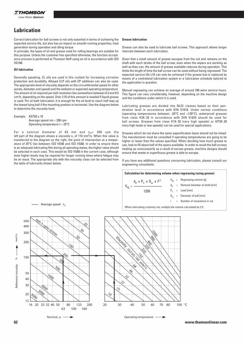
www.thomsonlinear.com62Nominal Operating temperature
Ref
eren
ce v
isco
sity
Viscosity
Average speed nm
Correct lubrication for ball screws is not only essential in terms of achieving the expected service life, but also has an impact on smooth running properties, heat generation during operation and idling torque .In principle, the types of oil and grease used for rolling bearings are suitable for this purpose . Unless the customer has specified otherwise, the function accept-ance process is performed at Thomson Neff using an oil in accordance with ISO VG100 .
Lubrication
Oil lubrication
Generally speaking, CL oils are used in this context for increasing corrosion protection and durability . Alloyed CLP oils with EP additives can also be used . The appropriate level of viscosity depends on the circumferential speed (in other words, diameter and speed) and the ambient or expected operating temperature .The amount of oil required per ball revolution lies somewhere between 0 .3 and 0 .5 cm3/h, depending on the speed . Only 1/10 of this amount is needed if liquid grease is used . For oil bath lubrication, it is enough for the oil level to reach half way up the lowest lying ball if the mounting position is horizontal . Use the diagram below to determine the viscosity level .
Example: KGT63 x 10 Average speed nm = 200 rpm Operating temperature t = 25°C
For a nominal diameter of 63 mm and nm= 200 rpm the left part of the diagram shows a viscosity v1 of 110 mm2/s . When this value is transferred to the diagram on the right, the point of intersection at a temper-ature of 25°C lies between ISO VG46 and ISO VG68 . In order to ensure there is an adequate lubricating film during all operating states, the higher value should be selected in each case . This would be ISO VG68 in the current case, although even higher levels may be required for longer running times where fatigue may be an issue . The appropriate oils with this viscosity class can be selected from the table of lubricants shown below .
Grease lubrication
Grease can also be used to lubricate ball screws . This approach allows longer intervals between each lubrication .
Given that a small amount of grease escapes from the nut and remains on the shaft with each stroke of the ball screw, even when the wipers are working as well as they can, the amount of grease available reduces during operation . This limits the length of time the ball screw can be used without being regreased . The expected service life L10 can only be achieved if the grease lost is replaced by means of a centralized lubrication system or a lubrication schedule tailored to the application in question .
Manual regreasing can achieve an average of around 700 extra service hours . This figure can vary considerably, however, depending on the machine design and the conditions under which it is used .
Lubricating greases are divided into NLGI classes based on their pen-etration level in accordance with DIN 51818 . Under normal conditions (operating temperatures between -20°C and +120°C), waterproof greases from class K2K-20 in accordance with DIN 51825 should be used for ball screws . Greases from class K1K-20 (very high speeds) or KP2K-20 (very high loads or low speeds) can be used for special applications .
Greases which do not share the same saponification basis should not be mixed . The manufacturer must be consulted if operating temperatures are going to be higher or lower than the values specified . When deciding how much grease to use, look to fill about half of the space available . In order to avoid the ball screws heating up unnecessarily as a result of excess grease, machine designs should ensure that waste or superfluous grease is able to escape .
If you have any additional questions concerning lubrication, please consult our engineering consultants .
Calculation for determining volume when regreasing (using grease)
d0 x Ph x Dw x i0 .7
1250VRL =
VRL = Regreasing volume [g]
d0 = Nominal diameter of shaft [mm]
Ph = Lead [mm]
Dw = Diameter of ball [mm]
i = Number of revolutions in nut
When lubricating a dummy nut, multiply the volume calculated by 2 .5 .

www.thomsonlinear.com 63
Precision Screws
Reci
rcul
atin
g ba
ll sc
rew
s
Recommended lubricants
Viscosity class
ISO
VG 68
VG 100
VG 150
VG200
Not ISO
K 1 K 20
K 2 K 20
KP 2 K 20
KLÜBER
Crucolan 68
Klüberoil GEM1-68
Crucolan 100
Klüberoil GEM1-100
Crucolan 150
Klüberoil GEM1-150
Crucolan 220
Klüberoil GEM1-220
Centoplex 1 DL
Centoplex 2
Centoplex GLP 402
Isoflex NBU 15
Staburags NBU 8 EP
MOBIL
Vactra Oil Heavy Medium
Mobilgear 626/Vactra Oil No . 2*
Vactra Oil Heavy
Mobilgear 627
Vactra Oil Extra Heavy
Mobilgear 627
Mobil DTE Oil BB
Mobilgear 630 / Vactra Oil No . 4*
Mobilith AW1: (not available in Germany)
Mobilux EP1: (not available in Germany)
Mobilux 2
Mobilux EP2
Mobilgrease HP 222
Viscosity class
ISO
VG 68
VG 100
VG 150
VG200
Not ISO
K 1 K 20
K 2 K 20
KP 2 K 20
BP
Energol RC 68
Energol HLP-D 68
Energol GR-XP 68
Maccurat 68D*
Energol RC 100
Energol GR-XP 100
Energol RC 150
Energol GR-XP 150
Energol CS-HB 220
Energol CR-XP 220
Maccurat 220D*
Energrease LS 1
Energrease LS 2
Multi-purpose grease L 2
Energrease LS-EP 2
BP long-life grease
TOTAL FINA
Hydran G 68
Hydran G 100
Hydran G 150
Hydran G 220
Marson L 1
Marson L 2
Marson EPL 2
CASTROL
Hyspin AWS 68
Hyspin SP 68
Vario HDX Alpha SP 68
Alpha MW 68
Magnaglide D 68*
Hyspin AWS 100
Hyspin SP 100
Alpha SP 100
Alpha MW 100
Alpha SP 150
Alpha MW 150
Alpha SP 220
Alpha MW 220
Magnaglide D 220*
Available on request
Castrol Spheerol AP 2
Castrol product 783/46
Castrol ALV
Castrol product 783/46
ESSO
Teresso 68
Spartan EP 68
Febis K 68*
Circulating oil 100
Spartan EP 100
Nuto 150
Spartan EP 150
Nuto 220
Spartan EP 220
Febis K 220*
Beakon EP 1
Beakon 2
Unirex N 2 EXXON multi-purpose grease
Beakon EP 2
Ronex MP-D

www.thomsonlinear.com64
1.
1.
13. 15. 16.2.
2.
3. | 4.
3. | 4.
7.| 8.
7.| 8.
10.| 11.
10.| 11.
6.5.
6.5.
9.
9.
14.12.
K G T D 2 0 0 5 R HT 7
Ball screw drives/ball screws/KOKON®
Order Code Structure:Ball screw drive/ball screw
1. ProductKGT = Ball screw drive complete
2. Nut versionD = Version according to DIN 69051N = Thomson Neff versionG = Cylindrical with threadL = Shifted (FL)S = Special, according to drawing
3. Nominal thread diameter [mm]
4. Thread lead [mm]
5. Lead accuracyP3, P5, T5, T7
6. Thread directionRH = Right hand threadLH = Left hand thread
7. Screw end 1 Standard end form C, D, F, H, J, L, S, T, W, B, Z, see page 26 et seq .G = Annealed endK = According to customer‘s drawingX = Cut only
8. Reference to end length 1for G/K end length [mm]
9. Overall length [mm]
10. Screw end 2 Standard end form C, D, F, H, J, L, S, T, W, B, Z, see page 26 et seq .G = Annealed endK = According to customer‘s drawingX = Cut only 11. Reference to end length 2for G/K end length [mm]
12. Nut form and configurationFlanged side of the KGF nut and contact surface of the KGM Nut always showing towards screw end 1F = 1 Flanged nutM = 1 Cylindrical nutFM = 1 Preloaded double nut unit (1 KGF, 1 KGM)FF = 1 Preloaded double nut unit (2 KGF)MM = 1 Preloaded double nut unit (2 KGM)
13. Return systemE = Single linerM = Multi liner (MUS)D = End capK = Channel
14. WiperEE = ElastomerKK = Plastic00 = Without wiperZZ = One wiper on both sides with centering for spiral spring cover
15. Manufacturing processR = Rolled
16. Special version or with accessories0 = No1 = Yes (please describe)
1. ProductKGF = Flanged nutKGM = Cylindrical nut
2. Nut versionD = Version according to DIN 69051N = Thomson Neff versionG = Cylindrical with threadL = Shifted (FL)S = Special, according to drawing
3. Nominal thread diameter [mm]
1. ProductKOKON
2. Nominal thread diameter [mm]40
3. Thread lead [5/10 mm]
5. Lead accuracy [µm/300mm]
4. Thread lead [mm]
6. Thread directionRH = Right hand threadLH = Left hand thread
13. Return systemE = Single linerM = Multi liner (MUS)D = End capK = Channel
5. Stroke [mm]
6. Overall length [mm]
7. Preloading0 = No backlash1 = Preloaded
8. Drive shaft0 = Without feather key groove1 = With feather key groove
14. WiperEE = ElastomerKK = Plastic00 = Without wiperZZ = One wiper on both sides with centering for spiral spring cover
9. Installation positionK = According to customer‘s requirementA-D = Thomson Neff standard versions
Installation position (view from fixed bearing)
10. Special version or with accessories0 = No1 = Yes
Order Code Structure:KOKON®
Example:1 Ball screw drive complete with machined screw ends
E E K 1 0 5 1 0 0 3 K 0 2 513. 15. 16.14.12.
F E 0R
1.
5.
2. 3. | 4.
7.6.
5.
3.2.
6.
7. 8. 9. 10.
7.
Order Code Structure:Ball nut
1. K OKON 4 0
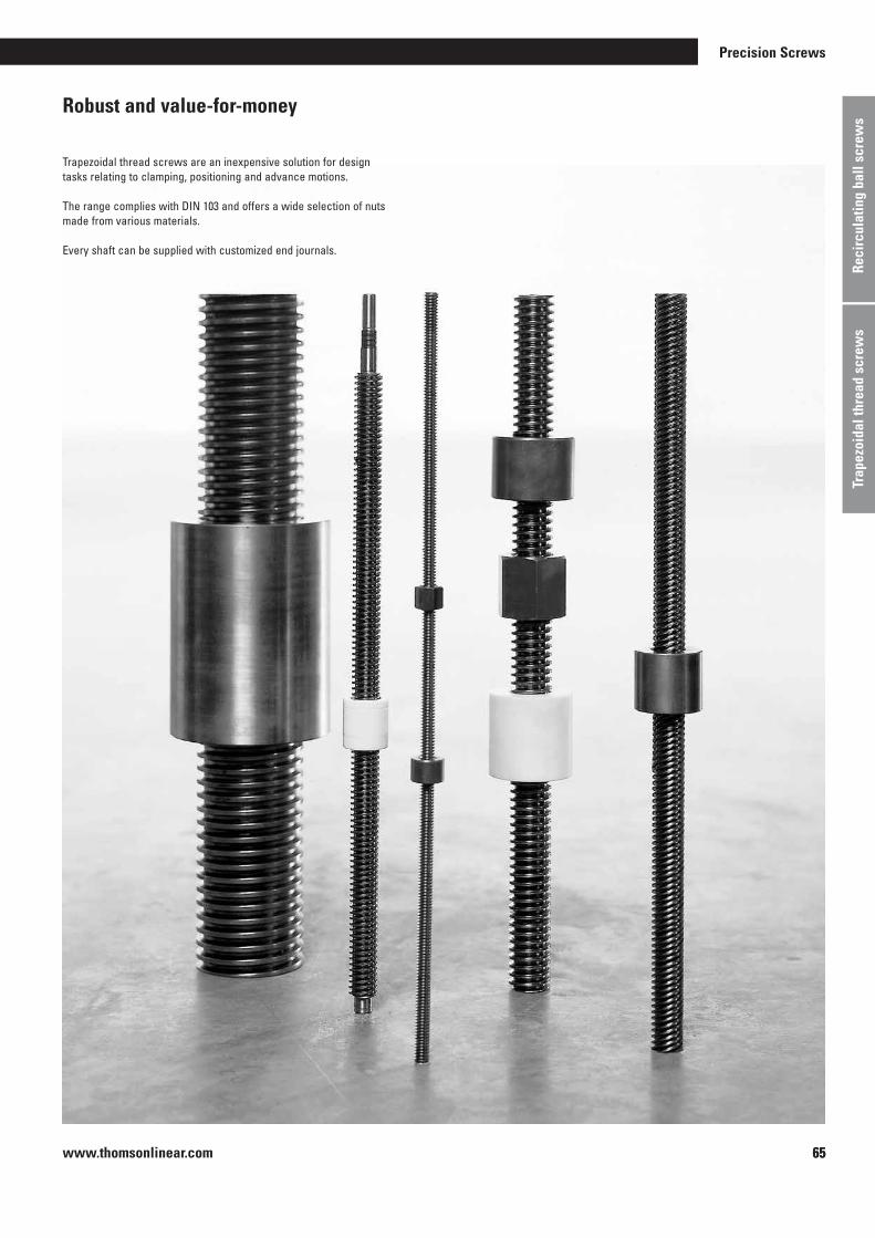
www.thomsonlinear.com 65
Trap
ezoi
dal t
hrea
d sc
rew
s
Precision Screws
65
Robust and value-for-money
Trapezoidal thread screws are an inexpensive solution for design tasks relating to clamping, positioning and advance motions .
The range complies with DIN 103 and offers a wide selection of nuts made from various materials .
Every shaft can be supplied with customized end journals .
Reci
rcul
atin
g ba
ll sc
rew
s
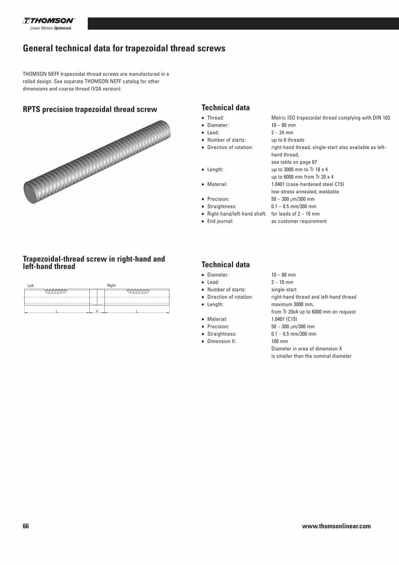
www.thomsonlinear.com66
General technical data for trapezoidal thread screws
THOMSON NEFF trapezoidal-thread screws are manufactured in a rolled design . See separate THOMSON NEFF catalog for other dimensions and coarse thread (V2A version) .
RPTS precision trapezoidal thread screw
Trapezoidal-thread screw in right-hand and left-hand thread
Technical data■ Thread: Metric ISO trapezoidal thread complying with DIN 103■ Diameter: 10 – 80 mm■ Lead: 2 – 24 mm■ Number of starts: up to 6 threads■ Direction of rotation: right-hand thread, single-start also available as left-
hand thread, see table on page 67
■ Length: up to 3000 mm to Tr 18 x 4 up to 6000 mm from Tr 20 x 4
■ Material: 1 .0401 (case-hardened steel C15) low-stress annealed, weldable
■ Precision: 50 – 300 µm/300 mm■ Straightness: 0 .1 – 0 .5 mm/300 mm■ Right-hand/left-hand shaft: for leads of 2 – 10 mm■ End journal: as customer requirement
Technical data■ Diameter: 10 – 80 mm■ Lead: 2 – 10 mm■ Number of starts: single-start■ Direction of rotation: right-hand thread and left-hand thread■ Length: maximum 3000 mm,
from Tr 20x4 up to 6000 mm on request■ Material: 1 .0401 (C15)■ Precision: 50 – 300 µm/300 mm■ Straightness: 0 .1 – 0 .5 mm/300 mm■ Dimension X: 100 mm
Diameter in area of dimension X is smaller than the nominal diameter
Left Right

www.thomsonlinear.com 67
Trap
ezoi
dal t
hrea
d sc
rew
s
Precision Screws
RPTS trapezoidal-thread screws
RPTS rolled precision trapezoidal thread screw
Manufacturing length 3000 mm, available up to 6000 mm length in diameters of 20 mm and greater . Dimension L as customer requirement .
Material: 1 .0401 (C15) .
Style DimensionExternal diameter [mm] [mm]Lead [mm]right-hand/left-hand d d2 min d2 max d3 1) H1 α2) η3)
RPTS Tr 10x2 10 8 .739 8 .929 6 .89 1 300 0 .5 4° 2’ 0 .40 0 .500 0 .011 0 .032 0 .51 · 10-5
RPTS Tr 10x3 8 .191 8 .415 5 .84 1 .5 300 0 .5 6° 24’ 0 .51 0 .446 0 .0057 0 .020 0 .40 · 10-5
RPTS Tr 12x3 12 10 .191 10 .415 7 .84 1 .5 300 0 .5 5° 11’ 0 .46 0 .68 0 .019 0 .047 0 .94 · 10-5
RPTS Tr 12x6 P35) 12 10 .165 10 .415 7 .84 1 .5 300 0 .5 10° 18’ 0 .62 0 .68 0 .019 0 .047 0 .94 · 10-5
RPTS Tr 14x3 14 12 .191 12 .415 9 .84 1 .5 300 0 .5 4° 22’ 0 .42 0 .96 0 .046 0 .094 1 .88 · 15-5
RPTS Tr 14x4 11 .640 11 .905 8 .80 2 300 0 .5 6° 3’ 0 .50 0 .888 0 .029 0 .067 1 .60 · 10-5
RPTS Tr 16x2 16 14 .729 14 .929 12 .89 1 50 0 .1 2° 36’ 0 .28 1 .39 0 .136 0 .210 3 .90 · 10-5
RPTS Tr 16x4 16 13 .640 13 .905 10 .80 2 50 0 .1 5° 11’ 0 .46 1 .21 0 .067 0 .124 2 .96 · 10-5
RPTS Tr 16x8 P45) 16 13 .608 13 .905 10 .80 2 300 0 .3 10° 18’ 0 .62 1 .21 0 .067 0 .124 2 .96 · 10-5
RPTS Tr 18x4 18 15 .640 15 .905 12 .80 2 50 0 .1 4° 32’ 0 .43 1 .58 0 .132 0 .206 5 .05 · 10-5
RPTS Tr 20x4 20 17 .640 17 .905 14 .80 2 50 0 .1 4° 2’ 0 .40 2 .00 0 .236 0 .318 8 .10 · 10-5
RPTS Tr 20x8 P45) 17 .608 17 .905 14 .80 2 200 0 .2 8° 3’ 0 .57 2 .00 0 .236 0 .318 8 .10 · 10-5
RPTS Tr 20x16 P45) 17 .608 17 .905 14 .80 2 200 0 .2 15° 47’ 0 .71 2 .00 0 .236 0 .318 8 .10 · 10-5
RPTS Tr 22x5 22 19 .114 19 .394 15 .50 2 .5 50 0 .1 4° 39’ 0 .43 2 .34 0 .283 0 .366 1 .11 · 10-4
RPTS Tr 22x24 P4 S5)6) 19 .140 19 .505 16 .50 2 200 0 .2 21° 34’ 0 .75 2 .34 0 .364 0 .441 1 .11 · 10-4
RPTS Tr 24x5 24 21 .094 21 .394 17 .50 2 .5 50 0 .1 4° 14’ 0 .41 2 .85 0 .460 0 .526 1 .65 · 10-4
RPTS Tr 24x10 P55) 21 .058 21 .394 17 .50 2 .5 200 0 .2 8° 25’ 0 .58 2 .85 0 .460 0 .526 1 .65 · 10-4
RPTS Tr 26x5 26 23 .094 23 .394 19 .50 2 .5 50 0 .1 3° 52’ 0 .39 3 .40 0 .710 0 .728 2 .35 · 10-4
RPTS Tr 28x5 28 25 .094 25 .394 21 .50 2 .5 50 0 .1 3° 34’ 0 .37 4 .01 1 .050 0 .976 3 .26 · 10-4
RPTS Tr 30x6 30 26 .547 26 .882 21 .90 3 50 0 .1 4° 2’ 0 .40 4 .50 1 .130 1 .030 4 .10 · 10-4
RPTS Tr 30x12 P65) 26 .507 26 .882 21 .90 3 200 0 .2 8° 3’ 0 .57 4 .50 1 .130 1 .030 4 .10 · 10-4
RPTS Tr 32x6 32 28 .547 28 .882 23 .90 3 50 0 .1 3° 46’ 0 .38 5 .19 1 .600 1 .340 5 .45 · 10-4
RPTS Tr 36x6 36 32 .547 32 .882 27 .90 3 50 0 .1 3° 18’ 0 .35 6 .71 2 .970 2 .130 9 .10 · 10-4
RPTS Tr 40x7 40 36 .020 36 .375 30 .50 3 .5 50 0 .1 3° 29’ 0 .37 8 .21 4 .250 2 .790 1 .37 · 10-3
RPTS Tr 40x14 P75) 35 .978 36 .375 30 .50 3 .5 200 0 .2 6° 57’ 0 .53 8 .21 4 .250 2 .790 1 .37 · 10-3
RPTS Tr 44x7 44 40 .020 40 .275 34 .50 3 .5 50 0 .1 3° 8’ 0 .34 10 .10 6 .950 4 .030 2 .10 · 10-3
RPTS Tr 48x8 48 43 .468 43 .868 37 .80 4 100 0 .1 3° 18’ 0 .35 12 .00 10 .000 5 .300 2 .90 · 10-3
RPTS Tr 50x8 50 45 .468 45 .868 39 .30 4 100 0 .1 3° 10’ 0 .34 13 .10 11 .700 5 .960 3 .40 · 10-3
RPTS Tr 60x9 60 54 .935 55 .360 48 .15 4 .5 200 0 .3 2° 57’ 0 .33 19 .00 26 .400 11 .000 7 .30 · 10-3
RPTS Tr 70x10 70 64 .425 64 .850 57 .00 5 200 0 .3 2° 48’ 0 .32 26 .00 51 .800 18 .200 1 .40 · 10-2
RPTS Tr 80x10 80 74 .425 74 .850 67 .00 5 200 0 .3 2° 25’ 0 .29 34 .70 98 .900 29 .500 2 .40 · 10-2
1) In a deviation from DIN 103 the minor diameter is slightly smaller for greater root rounding .
2) Pitch angle at the pitch diameter; → formula (XVI) p . 83 .3) Theoretical efficiency for the transformation of a rotary motion into an axial
motion at coefficient of friction µ = 0 .1 .
Efficiency for other coefficients of friction ; → formula (XVI) p . 83 .4) The polar resistance moment is twice as great as the resistance moment .5) Right-hand thread only .6) Special profile .
Nut
ShaftThread quality: 7e
Precision
[µm/ 300 mm]
Distributed load
[kg/m]
Straight-ness [mm/
300 mm]
Geometrical moment of
inertia [cm4]
Section modulus4)
[cm3]
Mass moment of
inertia [kg m2/m]
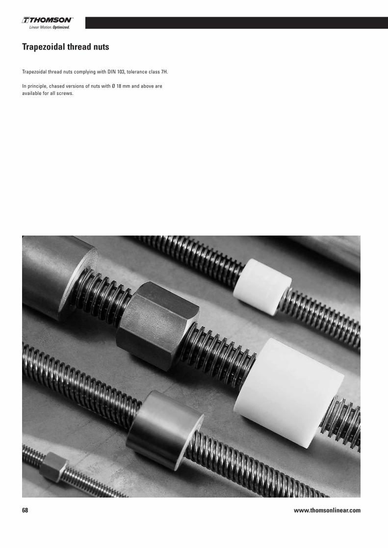
www.thomsonlinear.com68
Trapezoidal thread nuts
Trapezoidal thread nuts complying with DIN 103, tolerance class 7H .
In principle, chased versions of nuts with Ø 18 mm and above are available for all screws .

www.thomsonlinear.com 69
Trap
ezoi
dal t
hrea
d sc
rew
s
Precision Screws
Trapezoidal thread nuts
KSM short cylindrical steel nut blankSuitable for clamping, adjustment movements in manual operation and as a fixing nut . Not suited for motion systems as the steel-steel sliding pairing has a tendency to scuffing .
Further processing: The thread may be used as a reference for precise instructions on use and installation .
Material: Free-cutting steel 1 .0718 (9 SMn 28K) .
SKM hexagonal steel nutFor clamping, adjustment movements in manual operation and as a fixing nut . Not suited for motion systems as the steel-steel sliding pairing has a tendency to scuffing .
Further processing: The thread may be used as a reference for precise instructions on use and installation .
Material: Free-cutting steel 1 .0718 (9 SMn 28K) .
Style E C Mass [mm] [mm] [kg]
KSM Tr 10x2 22 15 0 .037
KSM Tr 10x3 22 15 0 .036
KSM Tr 12x3 26 18 0 .064
KSM Tr 14x3 30 21 0 .96
KSM Tr 14x4 30 21 0 .96
KSM Tr 16x4 36 24 0 .16
KSM Tr 18x4 40 27 0 .22
KSM Tr 20x4 45 30 0 .31
KSM Tr 22x5 45 33 0 .33
KSM Tr 24x5 50 36 0 .45
KSM Tr 26x5 50 39 0 .47
KSM Tr 28x5 60 42 0 .76
KSM Tr 30x6 60 45 0 .79
KSM Tr 32x6 60 48 0 .81
KSM Tr 36x6 75 54 1 .5
KSM Tr 40x7 80 60 1 .9
KSM Tr 44x7 80 66 2 .7
KSM Tr 48x8 90 72 2 .9
KSM Tr 50x8 90 75 2 .7
KSM Tr 60x9 100 90 3 .7
KSM Tr 70x10 110 105 4 .9
KSM Tr 80x10 120 120 6 .4
Style E C Mass [mm] [mm] [kg]
SKM Tr 10x2 17 15 0 .022
SKM Tr 10x3 17 15 0 .022
SKM Tr 12x3 19 18 0 .028
SKM Tr 14x3 22 21 0 .044
SKM Tr 14x4 22 21 0 .044
SKM Tr 16x4 27 24 0 .084
SKM Tr 18x4 27 27 0 .086
SKM Tr 20x4 30 30 0 .17
SKM Tr 22x5 30 33 0 .17
SKM Tr 24x5 36 36 0 .20
SKM Tr 26x5 36 39 0 .20
SKM Tr 28x5 41 42 0 .30
SKM Tr 30x6 46 45 0 .43
SKM Tr 32x6 46 48 0 .42
SKM Tr 36x6 55 54 0 .73
SKM Tr 40x7 65 60 1 .3
SKM Tr 44x7 65 66 1 .2
SKM Tr 48x8 75 72 1 .8
SKM Tr 50x8 75 75 1 .8
SKM Tr 60x9 90 90 2 .8
SKM Tr 70x10 90 105 3 .1

www.thomsonlinear.com70
Trapezoidal thread nuts
LRM long cylindrical gunmetal nutFor motion systems in continuous operation with particularly favorable wear characteristics . Suitable as safety nut .
Further processing: The thread may be used as a reference for pre-cise instructions on use and installation .
Material: 2 .1090 (G-CuSn 7Zn Pb (Rg7)), characteristics → page 72 .
Style E C Mass [mm] [mm] [kg] [mm2]
LRM Tr 10x2 22 20 0 .056 200
LRM Tr 10x3 22 20 0 .056 190
LRM Tr 12x3 26 24 0 .092 280
LRM Tr 12x6 P31) 26 24 0 .092 280
LRM Tr 14x3 30 28 0 .14 380
LRM Tr 14x4 30 28 0 .14 370
LRM Tr 16x2 36 32 0 .25 490
LRM Tr 16x4 36 32 0 .25 490
LRM Tr 16x8 P41) 36 32 0 .25 490
LRM Tr 18x4 40 36 0 .34 630
LRM Tr 20x4 45 40 0 .48 790
LRM Tr 20x8 P41) 45 40 0 .45 790
LRM Tr 22x5 45 40 0 .46 850
LRM Tr 22x24 P4S1) 2) 45 40 0 .46 880
LRM Tr 24x5 50 48 0 .69 1130
LRM Tr 24x10 P51) 50 48 0 .65 1130
LRM Tr 26x5 50 48 0 .58 1240
LRM Tr 28x5 60 60 1 .2 1680
LRM Tr 30x6 60 60 1 .2 1780
LRM Tr 30x12 P61) 60 60 1 .2 1780
LRM Tr 32x6 60 60 1 .2 1910
LRM Tr 36x6 75 72 2 .2 2610
LRM Tr 40x7 80 80 2 .8 3210
LRM Tr 40x14 P71) 80 80 2 .8 3210
LRM Tr 44x7 80 80 2 .6 3560
LRM Tr 48x8 90 100 4 .3 4840
LRM Tr 50x8 90 100 4 .2 5060
LRM Tr 60x9 100 120 5 .7 7320
LRM Tr 70x10 110 140 7 .6 10000
LRM Tr 80x10 120 160 9 .7 13200
1) Right-hand thread only .2) Special profile; nominal diameter 21 .5 .
Bearing length ratio

www.thomsonlinear.com 71
Trap
ezoi
dal t
hrea
d sc
rew
s
Precision Screws
Trapezoidal thread nuts
Style Dimensions [mm] Mass D1 D4 D5 6xD6 L1 L2 L3 [kg] [mm2]
EFM Tr 16x4 28 48 38 6 44 12 8 0 .25 670
EFM Tr 18x4 28 48 38 6 44 12 8 0 .25 770
EFM Tr 20x4 32 55 45 7 44 12 8 0 .30 870
EFM Tr 24x5 32 55 45 7 44 12 8 0 .30 1040
EFM Tr 30x6 38 62 50 7 46 14 8 0 .40 1370
EFM Tr 36x6 45 70 58 7 59 16 10 0 .60 2140
EFM Tr 40x7 63 95 78 9 73 16 10 1 .70 2930
EFM Tr 50x8 72 110 90 11 97 18 10 2 .60 4900
EFM Tr 60x9 85 125 105 11 99 20 10 3 .70 6040
EFM Tr 70x10 95 180 140 17 100 30 16 7 .80 8250
EFM Tr 80x10 105 190 150 17 110 30 16 8 .90 10890
LKM long cylindrical plastic nut
For low-noise motion systems with higher speeds and longer duty times . Especially recommended in combination with rolled trapezoi-dal lead screws . Good emergency running characteristics
Material: PETP, characteristics → page 72 .
Lubrication: FUCHS LUBRITEC, URETHYN EM 1 synthetic oil-based semi-fluid transmission grease
Style E C Mass [mm] [mm] [kg] [mm2]
LKM Tr 12x3 26 24 0 .012 280
LKM Tr 12x6 P3 26 24 0 .012 280
LKM Tr 16x4 36 32 0 .032 490
LKM Tr 16x8 P4 36 32 0 .032 490
LKM Tr 20x4 45 40 0 .06 790
LKM Tr 20x8 P4 45 40 0 .06 790
LKM Tr 24x5 50 48 0 .088 1130
LKM Tr 30x6 60 60 0 .15 1780
LKM Tr 30x12 P6 60 60 0 .15 1780
LKM Tr 36x6 75 72 0 .30 2610
LKM Tr 40x7 80 80 0 .37 3210
LKM Tr 50x8 90 100 0 .55 5060
Right-hand thread only, left-hand thread on request .
Bearing length ratio
Bearing length ratio
EFM complete bronze nutFor motion systems in continuous operation with particularly favora-ble wear characteristics . Suitable as safety nut .
EFM can be fitted with the KON and KAR adapters (→ pages 73–74) .
Material: 2 .1090 (G-CuSn 7Zn Pb (Rg7)), characteristics → page 72 .

www.thomsonlinear.com72
Trapezoidal thread nuts
EKM complete plastic nutsFor low-noise motion systems with higher speeds and longer duty times under moderate load . Good emergency run-ning characteristics . Especially recommended in combination with rolled trapezoidal lead screws .
Material: PETP, see below for characteristics .
Style Dimensions [mm] Mass ø D1 L1 L7 L8 WxD [kg/each [mm2]
EKM Tr 16x4 28 34 7 20 5x2 .9 0 .02 520
EKM Tr 20x4 32 34 7 20 5x2 .9 0 .03 670
EKM Tr 20x8P4 32 34 7 20 5x2 .9 0 .03 670
EKM Tr 20x16 P4 32 34 7 20 5x2 .9 0 .03 670
EKM with left-hand thread on request .
Material properties
Material 2.1090■ 0 .2 % yield point Rr0 .2: 120 N/mm2
■ Tensile strength Rm (δB): 240 N/mm2
■ Elongation at fracture A5 min .: 15 %■ Brinell hardness HB 10/1000: 65■ Density: 8 .8 kg/dm3
■ Modulus of elasticity: 90000 N/mm3
■ pv factor: 300 N/mm2 · m/min
Material PETP■ Tensile strength: 80 N/mm2
■ Modulus of elasticity: 2800 – 3000 N/mm2
■ Impact strength: 40 kJm2
■ Notched bar impact strength: 4 kJm2
■ Thermal expansion: 8,5 · 10-5/°C■ Water absorption: 0 .25 %■ Water saturation: 0 .6 %■ Density: 1 .38 kg/dm3
■ Friction against steel: 0 .05 – 0 .08■ Ball indentation hardness H 358/30: 150 N/mm2
■ Elongation at yield stress of 80 N/mm2: 4 – 5 %■ pv factor: 100 N/mm2 · m/min■ Maximum pressure per unit area: 10 N/mm2
■ Maximum sliding speed: 120 m/min
Bearing length ratio

www.thomsonlinear.com 73
Trap
ezoi
dal t
hrea
d sc
rew
s
Precision Screws
KON adapter support
Adapter support for radial fastening of EFM trapezoidal thread flanged nut .
Material: 1 .0065 (St37) or 1 .0507 (St52) .
Style Dimensions [mm]for EFM A1 A2 max
1) A2 min B1 B2 C1 C2 C4 D1 D4 Th x D
KON Tr 16x4/Tr 18x4 60 35 25 50 34 40 24 M 8x15 28 38 M 5x10
KON Tr 20x4/Tr 24x5 68 37 .5 29 58 39 40 24 M 8x15 32 45 M 6x12
KON Tr 30x6 75 42 .5 32 .5 65 49 40 24 M 10x15 38 50 M 6x12
KON Tr 36x6 82 45 37 75 54 50 30 M 10x12 45 58 M 6x12
KON Tr 40x7 120 70 50 100 76 65 41 M 14x25 63 78 M 8x14
KON Tr 50x8 135 77 .5 57 .5 115 91 88 64 M 16x25 72 90 M 10x16
KON Tr 60x9 152 87 .5 65 130 101 88 64 M 16x30 85 105 M 10x16
1) Standard = A2 max (as delivered)

www.thomsonlinear.com74
KAR universal joint adapter
Universal joint adapter for universally mounting on EFM trapezoidal thread flanged nut .
Material: 1 .0065 (St37) or 1 .0507 (St52) .
Dimensions [mm] A2 B1 B2 B3 C1 D1 D4 Th x D
KAR Tr 16x4/Tr 18x4 12 70 50 10 20 28 38 M 5x10
KAR Tr 20x4/Tr 24x5 16 85 58 13 .5 25 32 45 M 6x12
KAR Tr 30x6 18 95 65 15 25 38 50 M 6x12
KAR Tr 36x6 20 110 75 17 .5 30 45 58 M 6x12
KAR Tr 40x7 30 140 100 20 40 63 78 M 8x14
KAR Tr 50x8 40 165 115 25 50 72 90 M 10x16
KAR Tr 60x9 40 180 130 25 50 85 105 M 10x16
Style for EFM

www.thomsonlinear.com 75
Trap
ezoi
dal t
hrea
d sc
rew
s
Precision Screws
End journals for loose bearings/fixed bearingsForm D, FThe type of bearing selected influences the stiffness of the lead screw system as a whole and also the rotational vibration and buckling behavior of the lead screw shaft . The required end jour-nals are made for the trapezoidal lead screw according to the vari-ous types of bearing .
Note: Bearings are not supplied.
Relief groove form F DIN 509 Relief groove form E DIN 509
Thread undercut DIN 76–B
Form D Dimensions [mm] Bearing
TGT D1 D2 L1 L2 L3 L4 L5 M1 W1xD1 ZKLF…2RS
Tr 18/20/22x… 12 9 55 20 32 2 .5 16 M 12x1 3x1 .8 1255
Tr 24/26x… 15 11 58 23 35 3 .5 16 M 15x1 4x2 .5 1560
Tr 28/30/32x… 20 14 70 30 44 4 22 M 20x1 5x3 2068
Tr 36x… 25 19 82 40 57 6 28 M 25x1 .5 6x3 .5 2575
Tr 40/44/48/50x… 30 24 92 50 67 7 36 M 30x1 .5 8x4 3080
Form F Dimensions [mm] Bearing
TGT D1 D2 L1 L2 L3 L4 L5 M1 W1xD1 ZARN . . .LTN
Tr 22/24/26x… 15 11 73 23 35 3 .5 16 M 15x1 4x2 .5 1545
Tr 28/30/32x… 20 14 88 30 45 4 22 M 20x1 5x3 2052
Tr 28/30/32x… 20 14 107 30 50 4 22 M 20x1 5x3 2062
Tr 36/40/44x… 25 19 105 40 58 6 28 M 25x1 .5 6x3 .5 2557
Tr 36/40/44x… 25 19 120 40 63 6 28 M 25x1 .5 6x3 .5 2572
Tr 48/50x… 35 28 145 60 82 10 40 M 35x1 .5 8x4 3585
Tr 60/70x… 40 36 175 80 103 8 .5 63 M 40x1 .5 10x5 4090
Tr 80x… 55 48 215 110 136 10 90 M 55x2 14x5 .5 55115
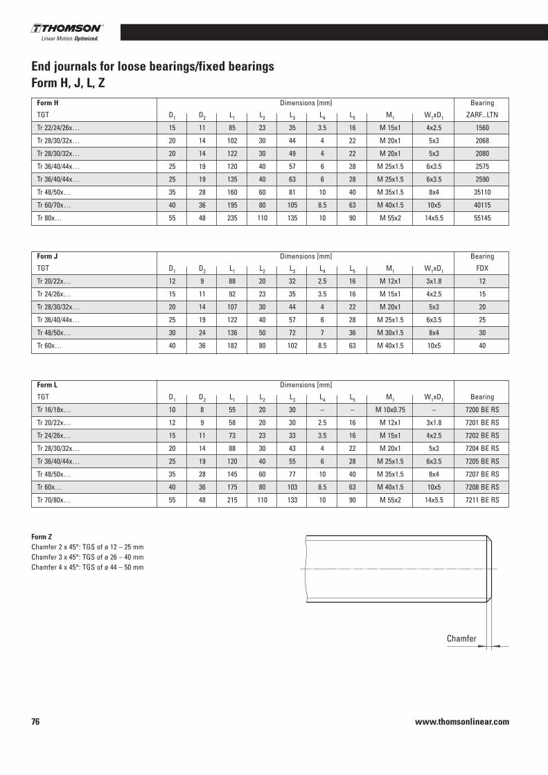
www.thomsonlinear.com76
End journals for loose bearings/fixed bearingsForm H, J, L, Z
Form H Dimensions [mm] Bearing
TGT D1 D2 L1 L2 L3 L4 L5 M1 W1xD1 ZARF . . .LTN
Tr 22/24/26x… 15 11 85 23 35 3 .5 16 M 15x1 4x2 .5 1560
Tr 28/30/32x… 20 14 102 30 44 4 22 M 20x1 5x3 2068
Tr 28/30/32x… 20 14 122 30 49 4 22 M 20x1 5x3 2080
Tr 36/40/44x… 25 19 120 40 57 6 28 M 25x1 .5 6x3 .5 2575
Tr 36/40/44x… 25 19 135 40 63 6 28 M 25x1 .5 6x3 .5 2590
Tr 48/50x… 35 28 160 60 81 10 40 M 35x1 .5 8x4 35110
Tr 60/70x… 40 36 195 80 105 8 .5 63 M 40x1 .5 10x5 40115
Tr 80x… 55 48 235 110 135 10 90 M 55x2 14x5 .5 55145
Form J Dimensions [mm] Bearing
TGT D1 D2 L1 L2 L3 L4 L5 M1 W1xD1 FDX
Tr 20/22x… 12 9 88 20 32 2 .5 16 M 12x1 3x1 .8 12
Tr 24/26x… 15 11 92 23 35 3 .5 16 M 15x1 4x2 .5 15
Tr 28/30/32x… 20 14 107 30 44 4 22 M 20x1 5x3 20
Tr 36/40/44x… 25 19 122 40 57 6 28 M 25x1 .5 6x3 .5 25
Tr 48/50x… 30 24 136 50 72 7 36 M 30x1 .5 8x4 30
Tr 60x… 40 36 182 80 102 8 .5 63 M 40x1 .5 10x5 40
Form L Dimensions [mm]
TGT D1 D2 L1 L2 L3 L4 L5 M1 W1xD1 Bearing
Tr 16/18x… 10 8 55 20 30 – – M 10x0 .75 – 7200 BE RS
Tr 20/22x… 12 9 58 20 30 2 .5 16 M 12x1 3x1 .8 7201 BE RS
Tr 24/26x… 15 11 73 23 33 3 .5 16 M 15x1 4x2 .5 7202 BE RS
Tr 28/30/32x… 20 14 88 30 43 4 22 M 20x1 5x3 7204 BE RS
Tr 36/40/44x… 25 19 120 40 55 6 28 M 25x1 .5 6x3 .5 7205 BE RS
Tr 48/50x… 35 28 145 60 77 10 40 M 35x1 .5 8x4 7207 BE RS
Tr 60x… 40 36 175 80 103 8 .5 63 M 40x1 .5 10x5 7208 BE RS
Tr 70/80x… 55 48 215 110 133 10 90 M 55x2 14x5 .5 7211 BE RS
Form ZChamfer 2 x 45°: TGS of ø 12 – 25 mmChamfer 3 x 45°: TGS of ø 26 – 40 mmChamfer 4 x 45°: TGS of ø 44 – 50 mm
Chamfer

www.thomsonlinear.com 77
Trap
ezoi
dal t
hrea
d sc
rew
s
Precision Screws
End journals for loose bearings/fixed bearingsForm S, T, W, K
Relief groove form E DIN 509 Groove for circlip DIN 471
Form S Dimensions [mm]
TGT D1 L1 L2 Spacer bushing Bearing
Tr 18/20x… 12 40 45 18x12 .1x24 6001 RS
Tr 22/24/26x… 15 46 51 21x15 .1x28 6002 RS
Tr 28/30/32x… 20 53 58 27x20 .1x29 6004 RS
Tr 36x… 25 53 58 32x25 .1x23 6205 RS
Tr 40/44/48/50x… 30 60 68 40x30 .1x28 6206 RS
Tr 60x… 40 80 88 50x40 .1x44 6208 RS
Tr 70/80x… 55 102 110 65x55 .1x60 6211 RS
Form T Dimensions [mm]
TGT D1 L1 L2 Inner ring Needle bearings
Tr 18/20x… 12 40 45 2 IR 12x16x20 HK 1614 RS
Tr 22/24/26x… 15 46 51 2 IR 15x20x23 HK 2018 RS
Tr 28/30/32x… 20 53 58 2 LR 20x25x26 .5 HK 2518 RS
Tr 36x… 25 53 58 2 LR 25x30x26 .5 HK 3018 RS
Tr 40/44/48/50x… 30 60 68 2 LR 30x35x30 HK 3518 RS
Tr 60x… 40 80 88 4 LR 40x45x20 HK 4518 RS
Form W Dimensions [mm]
TGT D1 L1 L2 Bearing
Tr 14/16x… 10 8 12 6000 RS
Tr 18/20x… 12 8 12 6001 RS
Tr 22/24/26x… 15 9 13 6002 RS
Tr 28/30/32x… 20 12 16 6004 RS
Tr 36x… 25 15 20 6205 RS
Tr 40/44/48/50x… 30 16 21 6206 RS
Tr 60x… 40 18 25 6208 RS
Tr 70/80x… 55 21 29 6211 RS
Form K: Special manufacture, in accordance with customer drawing .

www.thomsonlinear.com78
Calculation
Load capacity of trapezoidal thread screwsThe load capacity of sliding pairs is generally dependent on their material and surface properties, running in status, pressure per unit area, lubrication ratio, the sliding speed and the temperature and thus from the duty time and the options for heat dissipation .
The permissible pressure per unit area is primarily dependent on the sliding speed of the lead screw .
The pressure per unit area for motion systems should not exceed the maximum permissible value of the material .
The permissible speed can be calculated from the bearing length ratio of the nut (see tables on pages 70–72) and the pv factor of the nut material concerned (see page 72) .
pv factors
Material pv factors [N/mm2 · m/min]
G-CuSn 7 ZnPb (Rg 7) 300
G-CuSn 12 (G Bz 12) 400
Plastic (PETP) 100
Cast iron GG 22/GG 25 200
Required bearing length ratio
(VIII)
Maximum permissible sliding speed
(IX)
Maximum permissible speed
(X)
Permissible advance speed
(XI)
Aerf Required bearing length ratio [mm2]Fax Axial load acting [N]Pp Maximum permissible pressure per unit area
pv factor See tablevGp Maximum permissible sliding speed [m/min]
D Pitch diameter [mm]np Maximum permissible speed [rpm]
P Thread pitch [mm]sp Permissible advance speed [m/min]
Pp factors
Material Pp factors [N/mm²]
G-CuSn 7 ZnPb (Rg7) 10 - 20
G-CuSn 12 (G Bz 12) 10 - 20
Plastic (PETP) 5 - 10
Cast iron GG 22/GG 25 5
Maximum values valid for low duty cycles and low speed of travel .

www.thomsonlinear.com 79
Trap
ezoi
dal t
hrea
d sc
rew
s
Precision Screws
Calculation
Critical speed of trapezoidal thread screwsThere is a risk of resonance bending vibration in slender rotating components such as shafts . The method described below permits the estimation of the resonant frequency on the assumption of an adequately rigid installation . Speeds close to the critical speed fur-thermore considerably increase the risk of lateral buckling . The critical speed must, therefore, also be viewed in conjunction with the critical buckling force .
Maximum permissible shaft speed
(XII)
Theoretical critical speed ncr
np Maximum permissible shaft speed [rpm] ncr Theoretical critical shaft speed [rpm],
leading to resonance vibrations → see graphfcr Correction factor taking into consideration the type of shaft bearing → see table
! The operating speed may not be more than 80 % of the maximum speed
Bearing typesTypical values for the correction factor fcr corresponding to the classical installation situations for standard shaft bearings .
Theo
retic
al c
ritic
al s
peed
ncr
Unsupported length L
Case 1 Case 2
Case 3 Case 4
fcr = 0 .36 fcr = 1
fcr = 1 .47 fcr = 2 .23
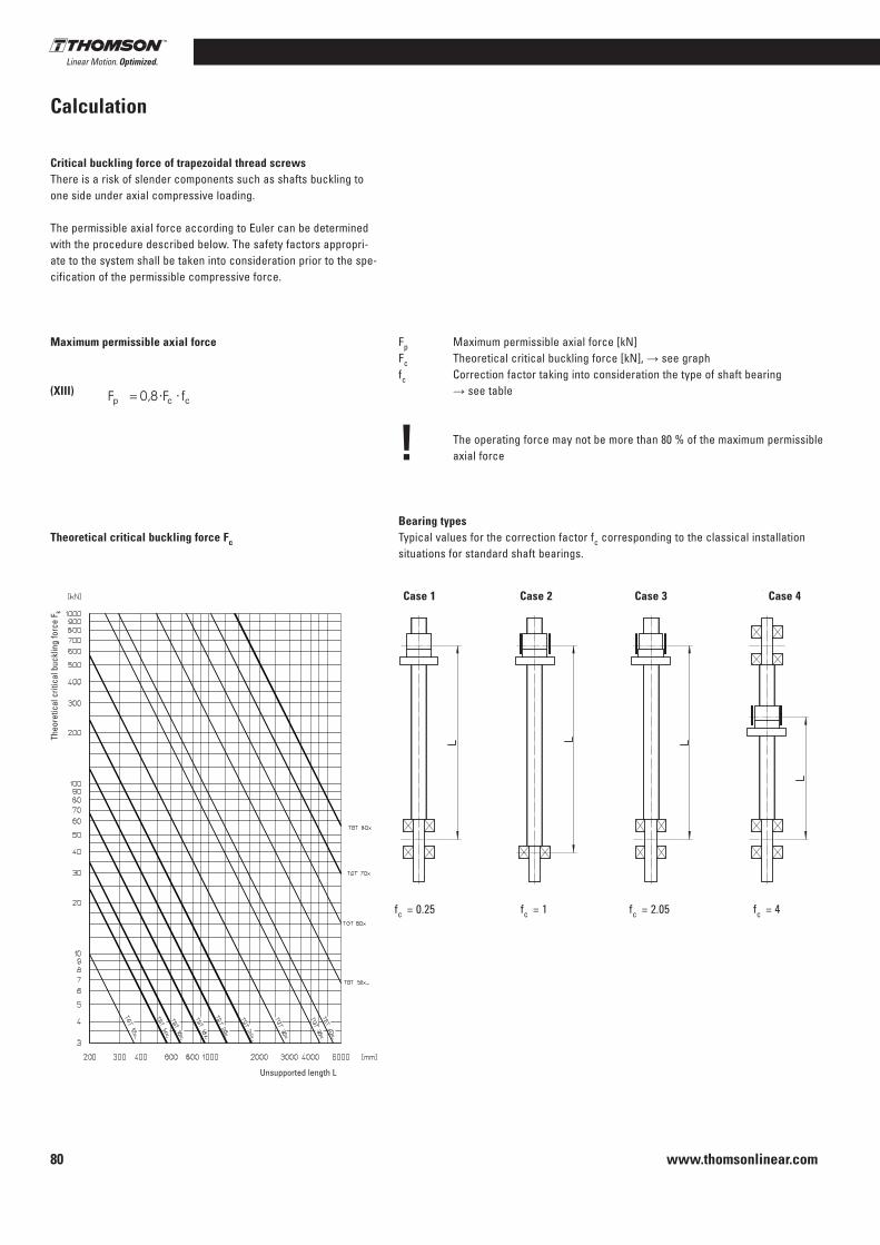
www.thomsonlinear.com80
Calculation
Critical buckling force of trapezoidal thread screwsThere is a risk of slender components such as shafts buckling to one side under axial compressive loading .
The permissible axial force according to Euler can be determined with the procedure described below . The safety factors appropri-ate to the system shall be taken into consideration prior to the spe-cification of the permissible compressive force .
Maximum permissible axial force
(XIII)
Theoretical critical buckling force Fc
Fp Maximum permissible axial force [kN] Fc Theoretical critical buckling force [kN], → see graphfc Correction factor taking into consideration the type of shaft bearing → see table
! The operating force may not be more than 80 % of the maximum permissible axial force
Bearing typesTypical values for the correction factor fc corresponding to the classical installation situations for standard shaft bearings .
Unsupported length L
Theo
retic
al c
ritic
al b
uckl
ing
forc
e F k
Case 1 Case 2 Case 3 Case 4
fc = 0 .25 fc = 1 fc = 4fc = 2 .05
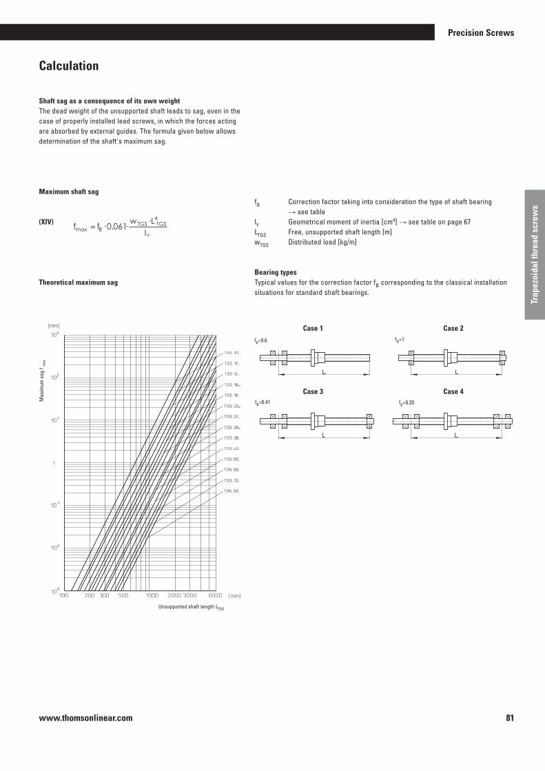
www.thomsonlinear.com 81
Trap
ezoi
dal t
hrea
d sc
rew
s
Precision Screws
Calculation
Shaft sag as a consequence of its own weightThe dead weight of the unsupported shaft leads to sag, even in the case of properly installed lead screws, in which the forces acting are absorbed by external guides . The formula given below allows determination of the shaft's maximum sag .
Maximum shaft sag
(XIV)
Theoretical maximum sag
fB Correction factor taking into consideration the type of shaft bearing → see tablelY Geometrical moment of inertia [cm4] → see table on page 67LTGS Free, unsupported shaft length [m]wTGS Distributed load [kg/m]
Bearing typesTypical values for the correction factor fB corresponding to the classical installation situations for standard shaft bearings .
Case 1 Case 2
Case 3 Case 4
Max
imum
sag
f m
ax
Unsupported shaft length LTGS
fB=0 .41
fB=9 .6
fB=0 .20
fB=1

www.thomsonlinear.com82
Calculation
Example calculation of trapezoidal screw
Given: Trapezoidal thread lead screw RPTS Tr 24x5 shaft Length L = 1500 mm Bearing journal case 2 Operating speed: nmax = 500 [rpm]
Maximum permissible shaft speed nzul
from (XII)
from (XIII)
from (XIV)
Result:
! ?Sought: Is the operating speed non-critical?
How great is the permissible axial force? How great is the maximum sag?
Theoretical critical speed ncr = 830 rpm → Theoretical critical speed graph
Theoretical critical buckling force Fc = 4 .2 kN → from Theoretical critical buckling force graph
Distributed load WTGS = 2 .85 kg/m Geometrical moment of inertia lY = 0 .460 cm4
→ from table on page 67
The lead screw selected is non-critical at nmax = 500 rpm .It can be loaded with a maximum axial load of 3 .36 kN and, mounted horizontally, will suffer a maximum sag of 1,91 mm .(Note pressure per unit area and pv factor)
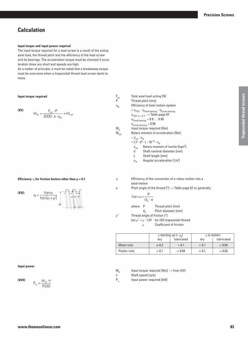
www.thomsonlinear.com 83
Trap
ezoi
dal t
hrea
d sc
rew
s
Precision Screws
Calculation
Input torque and input power requiredThe input torque required for a lead screw is a result of the acting axial load, the thread pitch and the efficiency of the lead screw and its bearings . The acceleration torque must be checked if acce-leration times are short and speeds are high . As a matter of principle, it must be noted that a breakaway torque must be overcome when a trapezoidal thread lead screw starts to move .
Input torque required
(XV)
Efficiency η for friction factors other than µ = 0.1
(XVI)
Input power
(XVII)
µ starting up (= µ0) µ in motion dry lubricated dry lubricated
Metal nuts ≈ 0 .3 ≈ 0 .1 ≈ 0 .1 ≈ 0 .04
Plastic nuts ≈ 0 .1 ≈ 0 .04 ≈ 0 .1 ≈ 0 .03
Fax Total axial load acting [N]P Thread pitch [mm]ηA Efficiency of total motion system = ηTGT · ηFixed bearing · ηLoose bearing ηTGT (µ = 0 .1) → Table page 67 ηFixed bearing = 0 .9 … 0 .95 ηLoose bearing = 0 .95Md Input torque required [Nm]Mrot Rotary moment of acceleration [Nm]
= Jrot · α0 = 7,7 · d4 · L · 10-13 · α0
Jrot Rotary moment of inertia [kgm2] d Shaft nominal diameter [mm] L Shaft length [mm] α0 Angular acceleration [1/s2]
η Efficiency of the conversion of a rotary motion into a axial motionα Pitch angle of the thread [°] → Table page 67 or generally:
where P Thread pitch [mm] d2 Pitch diameter [mm]r’ Thread angle of friction [°] tan r’ = µ · 1 .07 for ISO trapezoidal thread
µ Coefficient of friction
Md Input torque required [Nm] → from (XV)n Shaft speed [rpm]Pa Input power required [kW]

www.thomsonlinear.com84
Calculation
Torque as a consequence of an axial loadTrapezoidal lead screws, the pitch angle α of which is greater than the friction angle r’ are considered non-self locking . This means that an axial force applied generates a resulting torque on the shaft . The efficiency η’ for the conversion of an axial motion into a rotary motion is less than that for the conversion of a rotary motion into an axial motion .
Holding torque required
(XVIII)
Fax Total axial load acting [N]P Thread pitch [mm]η’ Efficiency of the conversion of an axial motion into a rotary motion
The influence of the efficiency of the bearings can be ignored .
Md’ Holding torque required [Nm]Mrot Rotary moment of acceleration [Nm]
= Jrot · α0 = 7 .7 · d4 · L · 10-13
Jrot Rotary moment of inertia [kgm2] d Shaft nominal diameter [mm] L Shaft length [mm] α0 Angular acceleration [1/s2]

www.thomsonlinear.com 85
Trap
ezoi
dal t
hrea
d sc
rew
s
Precision Screws
KW splined shaftsMaterial: CK 45 .Based on DIN 5463 .
SR sliding sleeve blankMaterial: 9 Smn 28 K .Based on DIN 5463 .
EK complete clamping ringMaterial: C 45, surface burnished . Drillings match ES .Based on DIN 5463 .
Designation Dimensions [mm] Weight ø D ø d b [kg/m] -0 .07 +0 .0 +0 .0 -0 .27 -0 .08 -0 .08
KW 16 20 16 4 1 .90
KW 21 25 21 5 2 .10
KW 26 32 26 6 5 .00
KW 42 48 42 8 12 .30
KW 46 54 46 9 15 .30
Straightness: 0 .5 – 0 .6 mm/300 mmStraightness: 0 .1 mm/300 mm on request
Designation Dimensions [mm] Weight ø d b ø E L [kg/each] G6 F9
SR 16 16 4 40 35 0 .25
SR 21 21 5 45 43 0 .40
SR 26 26 6 60 59 1 .00
SR 42 42 8 90 71 2 .60
SR 46 46 9 90 95 3 .25
Designation Dimensions [mm] Weight ø d b ø C [kg/each] G6 F9 ø A ø B ø B1 ø B2 e f7 K L
EK 16 6 16 4 52 38 5 .3 10 6 26 2 14 0 .20
EK 21 6 21 5 62 48 6 .4 11 7 35 3 14 0 .25
EK 26 6 26 6 70 56 6 .4 11 7 40 3 15 0 .25
EK 42 8 42 8 95 75 10 .5 18 11 60 3 22 0 .85
EK 46 8 46 9 99 80 10 .5 18 11 65 3 24 0 .95
Number of grooves

www.thomsonlinear.com86
ES complete sliding sleeveMaterial: C 45, Grooves do not match bores .Based on DIN 5463 .
ESS complete sliding sleeve made from special bronzeMaterial: High-quality bronze GBZ 12, Grooves do not match bores .Based on DIN 5463 .
Designation Dimensions [mm] Weight ø d b ø C ø F [kg/each] G6 F9 ø A ø B ø B1 H7 h h7 L E
ES 16 6 16 4 52 38 5 .3 26 3 28 35 9 0 .20
ES 21 6 21 5 62 48 6 .4 35 3 .5 34 50 10 0 .30
ES 26 6 26 6 70 56 6 .4 40 3 .5 42 60 10 0 .50
ES 42 8 42 8 95 75 10 .5 60 4 60 90 16 1 .30
ES 46 8 46 9 99 80 10 .5 65 4 65 100 16 1 .50
Designation Dimensions [mm] Weight ø d b [kg/each] G6 F9 D1 D4 D5 D6 L1 L2 L3
ESS 16 6 16 4 28 48 38 6 44 12 8 0 .25
ESS 21 6 21 5 32 55 45 7 44 12 8 0 .30
ESS 26 6 26 6 38 62 50 7 46 14 8 0 .40
ESS 42 8 42 8 63 95 78 9 73 16 10 1 .45
ESS 46 8 46 9 72 110 90 11 97 18 10 2 .25
-0 .2
1-0 .
1
Number of grooves
Number of grooves

www.thomsonlinear.com 87
Trap
ezoi
dal t
hrea
d sc
rew
s
Precision Screws
TGT trapezoidal thread screwsInstallationTrapezoidal thread screws must be carefully aligned on installation – if the appropriate measuring equipment is not available, the lead screw shall be moved once by hand over the entire length before the input unit is fitted . Uneven force requirements and/or running traces on the external diameter of the shaft here indicate errors in the alignment between shaft axis and guide . In this case, first slacken off the relevant mounting screws and then operate the lead screw once again by hand . If the force requirement is now uniform, the corresponding elements must be aligned, otherwise the alignment error must be determined by slackening further mounting screws .
CapsTrapezoidal thread screws are inherently less sensitive to contamination than recirculating ball screws, especially at low speeds (e .g . manual operation) .
Motion drives, in particular those using plastic nuts, however, also require protective measures similar to those for recirculating ball screws .
Lubrication
Oil lubricationIs only used on trapezoidal thread screws in special cases .
Grease lubricationThis is the usual lubrication for trapezoidal thread screws . The lubrication intervals depend on the operating conditions; it is recommended that the shaft is cleaned before being greased, especially if high performance lubri-cating systems are being used .Grease grades: roller bearing greases without a solid lubricant constituent .
Operating temperatureDepends on the nature of the nut used, the lubricating conditions and the requirements made . Please consult us for operation at temperatures in excess of 100 °C (in excess of 70 °C for plastic nuts) .
WearMay be tested by hand; the nut must be replaced if the axial play of a single thread lead screw is greater than 1/4 of the lead .
Installation and maintenance

www.thomsonlinear.com88
1. 7.2. 4. 9.8.
Tr X5. 6.3.
P10. 11. 12.
1. 7.2. 4. 9.8.
T G S LTr X R P T S 1 0 0 9 0 0 5.
0 56.
R H3.
0 2 4 P10. 11.
W12.
0
1. 2. 4.
T G M Tr X L R M 1 05.
0 56.
R H3.
0 2 4 P
3.1.
S F2. 4. 5.
3.1.
KW2.
4 2
Trapezoidal thread screw/helical spring cover/splined shafts
The structure of the order codeTrapezoidal thread screws
1. Product TGS = trapezoidal-thread screw shaft TGM = Trapezoidal thread nut
2. Type Shaft RPTS Nut: LKM, EKM, KSM, SKM,
LRM, EFM
3. Thread nominal diameter [mm]
4. Thread lead [mm]
5. Thread pitch [mm] Only in the case of multiple-start
threads: The distance between two consecutive threads in the axial direction = pitch/number of starts
6. Thread direction RH = right hand thread LH = left hand thread
7. Shaft end 1 Standard end form D, F, H, J, L, S, T,
W, Z, see pages 75 et seq . K = in accordance with attached customer drawing X = separating only
8. Reference to end length 1 End length for version K [mm]
9. Overall length of TGS [mm]
10. Shaft end 2 Standard end form D, F, H, J, L, S, T, W,
Z, see pages 75 et seq . K = in accordance with attached customer drawing X = separating only 11. Reference to end length 2 End length for version K [mm]
12. Special designs or with accessories O = no 1 = yes
Ordering example:1 Trapezoidal thread nut
1. Product TGM = Trapezoidal thread nut
2. Type Nut: LRM
3. Thread nominal diameter [mm] 24
4. Thread lead [mm] 10
5. Thread pitch [mm] 5
6. Thread direction RH = right hand thread
The structure of the order codeHelical spring cover
1. Product SF = Helical spring cover
2. Minimum diameter D8 [mm]
3. Overall length [mm]
4. Minimum length L8 [mm]
5. Mounting position V = vertical H = horizontal
The structure of the order codesplined shaft
1. Product KW = splined shaft
Ordering example:1 Trapezoidal-thread lead screw with shaft ends
1. Product TGS = trapezoidal-thread screw shaft
2. Type Shaft RPTS
3. Thread nominal diameter [mm] 24
4. Thread lead [mm] 10
5. Thread pitch [mm] 5
6. Thread direction RH = right hand thread
7. Shaft end 1 Standard end form L 9. Overall length of TGS [mm] 900
10. Shaft end 2 Standard end form W
12. Special designs or with accessories O = no
2. Size 3. Length [mm]

www.thomsonlinear.com 89
Trap
ezoi
dal t
hrea
d sc
rew
s
Precision Screws
Notes

www.thomsonlinear.com90
With their easy running, precise and cost-effective positioning function, lead screws offer the optimum solution for your application.The Thomson Neff precision lead screws manufactured by Thomson Neff are an outstanding and economical solution to your linear motion requirements . Thomson Neff has been active for more than 25 years developing and producing the highest quality lead screws in this industrial sector . Our precision rolling process guarantees precision positioning to 0 .075 mm/300 mm, and our coating method using PTFE creates systems with a lower drag torque and a higher service life .
Thomson Neff has a wide range of standard plastic nuts systems available, in the form of anti-backlash or standard Supernuts® . A composite material of acetal and PTFE is used in all these standard plastic nut systems, offering an outstanding lubricant capability with or without supplementary lubrication, at the same time achieving a low rate of wear . As a result of the introduction of our new, unique patented backlash-free method design, Thomson Neff is able to offer systems with high axial stiffness, zero backlash and a very low drag torque, reducing the demands on the motor . This creates more cost-effective products with a higher performance and longer service life . The two designs automatically adapt to the wear conditions, so that zero backlash is guaranteed for the life of the nut .
Thomson Neff also offers a design service for your application requirements. This means that lead screws can be manufactured to meet your specifications. Get in touch with Thomson Neff today and discuss your application with our experienced product specialists.
Supply optionsReducing backlash is of decisive importance in ensuring precise positioning . Several types of preload variants, which all use a resilient preload are available on the market . As these mechanisms are only limited in their stiffness, a high preload is necessary to retain the position . This leads to a high drag torque, shorter service life and reduced performance . The costs forthe system increase and a larger motor is required .
The solution – THOMSON NEFFWith the introduction of the patented XC series of nuts with ActiveCAM, optimum axial stiffness with minimum drag torque at the same time is achieved . The use of a an extremely stiff stainless steel sleeve for the preload leads to an incomparable axial stiffness . The axial backlash is rectified without high preloading and so the lowest possible drag torque is achieved .
Readjusting the preloading following wearThe wear occurring over time is automatically compensated for by the unique ActiveCAMmechanism, without sacrificing stiffness and positioning accuracy, or influencing the drag torque .US Patent #5839321 and one or more foreign equivalents .

www.thomsonlinear.com 91
Trap
ezoi
dal t
hrea
d sc
rew
s
Precision Screws
Quality lead screws
- ActiveCAM technology- High-quality plastic nuts- High precision
Fields of application for lead screws
Medical equipment
Semiconductor production
Engraving machines
Laboratory equipment

www.thomsonlinear.com92
Features/benefitsLow costs Considerable savings over ball screws .
Variety Huge selection of leads and diameters .
Lubrication Internally lubricated plastic nuts may be used without supplementary lubrication . We nevertheless recommend the use of TriGEL grease or a dry lubricant to extend the service life . See page 100 .
Vibration and noise generation No vibration from ball recirculation and frequently less audible noise generation by comparison with recirculating ball screws .
Aspects of the designLoad Supernuts are a cost-effective solution for medium to light loading . In vertical applications, the Anti-Backlash Supernuts should be mounted with the thread/flange on the underside .
Unilateral load Unilateral loads that may exert a torque on the nut will lead to premature failure .
Critical speed See critical speed graph on page 93 .
Buckling load See buckling load graph on page 94 .
Self-locking Lead screws can be self-locking at small leads . For the best possible operating conditions, the shaft pitch should always be greater than 1/3 of the nominal diameter .
Customized solution Ability to adapt the components to your application .Corrosion resistant* Stainless steel shafts, Acetal nuts .Environment Less susceptible to contamination by particles than recirculating ball screws .Low weight There is less mass to move .Temperature The heat generated by the environment and friction is the principal cause for premature failure of the plastic nuts . Note the limit values for temperature listed below and discuss your application with regard to continuous operation, high loading and high-speed applications with our product specialists . Thomson Neff recommends bronze nuts for very high temperature environments . We will also be pleased to advise you on the selection of a high temperature plastic for a custom application .Efficiency The following is true except for very large leads: the greater the lead, the better the efficiency . Even though acetal in combination with PTFE has excellent lubricating properties, recirculating ball screws have significantly greater efficiency than lead screws . See page 99 for the actual efficiency .Length limit values Shaft diameter maximum length 10 mm 1200 mm 12 – 16 mm 1800 mm >16 mm 3600 mmPitch precision Standard quality (SRA) 250 µm/300 mm Precision quality (SPR) 75 µm/300 mm
Precision lead screws and Supernuts®
Useful formulas for lead screws
TORQUE, ROTARY LINEARDrive on the shaft to move the nut, or drive on the nut to move the shaft .
Torque = load (N) x lead (mm)(Nmm) 2p x efficiency
TORQUE, LINEAR ROTARY Load on the nut to rotate the shaft .
As a rule, the following is true: Systems with an efficiency of 50 % and greater are not self-locking . For efficiency see page 99 . The efficiencies listed in the catalog are calculated for a coefficient of friction of 0 .1 .
% efficiency = tan (pitch angle) x 100 tan (pitch angle + “arctan” f)
f = coefficient of friction
EFFICIENCY
Torque = load x lead x efficiency 2p
Mounting Shafts Nuts**
82 °C 0 .08 - 0 .14 Stainless steel* Acetal with PTFE 55 N/mm2 0 .15 9 .7 x 10-5 1/°C
* 1 .4301 (AISI 304) and 1 .4305 (AISI 303) ** Other materials available on a custom basis .
Water absorption (24 hour %)
Coefficient of thermal expan-
sionMaximum
temperatureCoefficient of
frictionTensile strengthMaterial Material
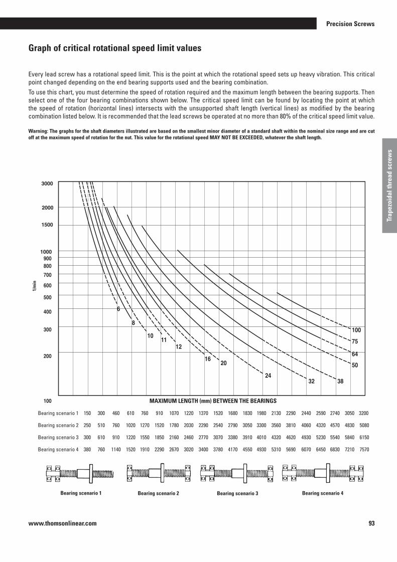
www.thomsonlinear.com 93
Trap
ezoi
dal t
hrea
d sc
rew
s
Precision Screws
Graph of critical rotational speed limit values
Every lead screw has a rotational speed limit . This is the point at which the rotational speed sets up heavy vibration . This critical point changed depending on the end bearing supports used and the bearing combination .To use this chart, you must determine the speed of rotation required and the maximum length between the bearing supports . Then select one of the four bearing combinations shown below . The critical speed limit can be found by locating the point at which the speed of rotation (horizontal lines) intersects with the unsupported shaft length (vertical lines) as modified by the bearing combination listed below . It is recommended that the lead screws be operated at no more than 80% of the critical speed limit value .
Warning: The graphs for the shaft diameters illustrated are based on the smallest minor diameter of a standard shaft within the nominal size range and are cut off at the maximum speed of rotation for the nut. This value for the rotational speed MAY NOT BE EXCEEDED, whatever the shaft length.
MAXIMALE LÄNGE (mm) ZWISCHEN DEN LAGERN
1/m
in
3000
2000
1500
1000
Bearing scenario 1 Bearing scenario 2 Bearing scenario 3 Bearing scenario 4
Bearing scenario 1 150 300 460 610 760 910 1070 1220 1370 1520 1680 1830 1980 2130 2290 2440 2590 2740 3050 3200
Bearing scenario 2 250 510 760 1020 1270 1520 1780 2030 2290 2540 2790 3050 3300 3560 3810 4060 4320 4570 4830 5080
Bearing scenario 3 300 610 910 1220 1550 1850 2160 2460 2770 3070 3380 3910 4010 4320 4620 4930 5230 5540 5840 6150
Bearing scenario 4 380 760 1140 1520 1910 2290 2670 3020 3400 3780 4170 4550 4930 5310 5690 6070 6450 6830 7210 7570
MAXIMUM LENGTH (mm) BETWEEN THE BEARINGS
1/m
in
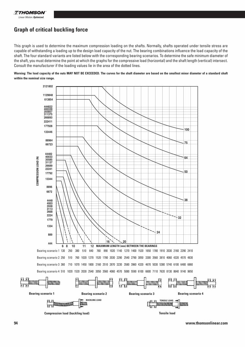
www.thomsonlinear.com94
MAXIMALE LÄNGE (mm) ZWISCHEN DEN LAGERN
DR
UC
KB
EAN
SPR
UC
HU
NG
(N)
Graph of critical buckling force
This graph is used to determine the maximum compression loading on the shafts . Normally, shafts operated under tensile stress are capable of withstanding a loading up to the design load capacity of the nut . The bearing combinations influence the load capacity of the shaft . The four standard variants are listed below with the corresponding bearing scenarios . To determine the safe minimum diameter of the shaft, you must determine the point at which the graphs for the compressive load (horizontal) and the shaft length (vertical) intersect . Consult the manufacturer if the loading values lie in the area of the dotted lines .
Warning: The load capacity of the nuts MAY NOT BE EXCEEDED. The curves for the shaft diameter are based on the smallest minor diameter of a standard shaft within the nominal size range.
Bearing scenario 1 Bearing scenario 2 Bearing scenario 3 Bearing scenario 4
Compression load (buckling load) Tensile load
Bearing scenario 1 130 250 380 510 640 760 890 1020 1140 1270 1400 1520 1650 1780 1910 2030 2160 2290 2410
Bearing scenario 2 250 510 760 1020 1270 1520 1780 2030 2290 2540 2790 3050 3300 3560 3810 4060 4320 4570 4830
Bearing scenario 3 360 710 1070 1450 1800 2160 2510 2870 3230 3580 3960 4320 4670 5030 5380 5740 6100 6480 6860
Bearing scenario 4 510 1020 1520 2030 2540 3050 3560 4060 4570 5080 5590 6100 6600 7110 7620 8130 8640 9140 9650
TENSILE LOADBUCKLING LOAD
MAXIMUM LENGTH (mm) BETWEEN THE BEARINGS
COM
PRES
SIO
N L
OA
D (N
)

www.thomsonlinear.com 95
Trap
ezoi
dal t
hrea
d sc
rew
s
Precision Screws
Bearing scenario 1 130 250 380 510 640 760 890 1020 1140 1270 1400 1520 1650 1780 1910 2030 2160 2290 2410
Bearing scenario 2 250 510 760 1020 1270 1520 1780 2030 2290 2540 2790 3050 3300 3560 3810 4060 4320 4570 4830
Bearing scenario 3 360 710 1070 1450 1800 2160 2510 2870 3230 3580 3960 4320 4670 5030 5380 5740 6100 6480 6860
Bearing scenario 4 510 1020 1520 2030 2540 3050 3560 4060 4570 5080 5590 6100 6600 7110 7620 8130 8640 9140 9650
2 3 4 5 6 8 10 12 15 16 20 25 35 45
10 • • • • • • •
12 • • • • • • • •
16 • • • • • •
20 • • • • • •
24 •
Inch
Dia
met
er (i
nche
s)
Series Thomson Neff precision lead screw
Lead screw product features
Lead screw product availabilityMetric
• = size with right hand thread in stock = size with left hand thread in stock
Lead (mm)
Dia
met
er (m
m)
0 .050 0 .063 0 .083 0 .100 0 .125 0 .167 0 .200 0 .250 0 .375 0 .500 0 .800 1 .000 1 .200 2 .000
3/8 • • • • • • • • • • •
7/16 • • •
1/2 • • • • • • •
5/8 • • • • •
3/4 • • • • • • •
1 • • • • • •
Lead (inches)
Lead precision
Diameter
Lead
Backlash
Dynamic load
Maximum static load
Catalog page
Standard - 250 µm/300 mmPrecision - 75 µm/300 mm
10 to 24 mm
2 to 45 mm
0 .02 to 0 .25 mm (standard nut) backlash-free version available
up to 1550 N
up to 6675 N
70 to 72
Lead screws in inch dimensions are also available . Further information may be found on the Internet at www.thomsonlinear.com
Note: Miniature sizes are also available . Information may be found on the Internet at www.thomsonlinear.com Customized diameters and leads on request .

www.thomsonlinear.com96
Ordering information
Thomson Neff designs the lead screws for optimum performance . To ensure correct operation, it is recommended that our nuts and shafts are used only with the appropriate Thomson Neff products, as manufactured by Thomson Neff . This is of particular importance in the case of our own thread dimensions . Select a shaft size complying with DIN from page 99 if interchangeability is a requirements criterion .
The use of a lubricant is recommended for the operation of a lead screw with a plastic nut . This increases the service life of the unit and the permissible operating load . Note: The load indications in the catalog are based on the use of a lubricant . See pages 100 and 101 for lubrication options .
Nut part number (see pages 97 and 98)
Example
Note: Make sure that nut you selected is offered for use with the shaft diameter selected . See “Shaft series” on pages 97 and 98 to verify .
Shaft part numbers (see page 99)
Example
Shaft length (please state units - preferably mm)
Prefix for nut style number (letters only - 2 or 3 characters)
Shaft size from table on page 99. (No statement of precision prefix)
Precision prefix (3 letters for precision or standard accuracy)
Shaft size (indication of diameter and lead)
X C B 10x2M
S P T 10x2M 150 mm
-
The shaft and nut are designed to work together properly where these two components have the same suffix for the shaft size (see examples listed above) .
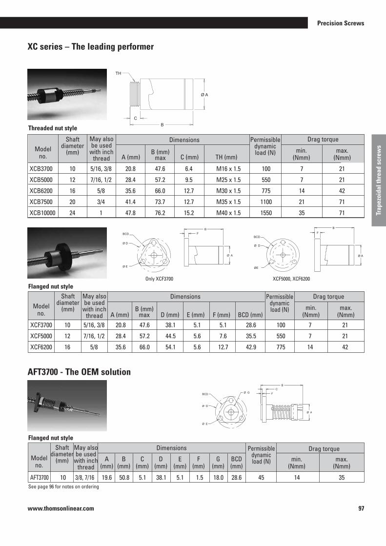
www.thomsonlinear.com 97
Trap
ezoi
dal t
hrea
d sc
rew
s
Precision Screws
XC series – The leading performer
AFT3700 - The OEM solution
CB
Ø A
TH
Threaded nut style
Ø G FC
B
Ø E
BCD
Ø D
Ø A
Only XCF3700
See page 96 for notes on ordering
BF
BCD
Ø D
ØE
Ø A
XCF5000, XCF6200
BCD
Ø D
BF
Ø E
Ø A
Model no .
Shaft diameter
(mm)
May also be used
with inch thread
Permissible dynamic load (N)
A (mm)B (mm)
max C (mm) TH (mm)min .
(Nmm)max .
(Nmm)
Drag torque
XCB3700 10 5/16, 3/8 20 .8 47 .6 6 .4 M16 x 1 .5 100 7 21
XCB5000 12 7/16, 1/2 28 .4 57 .2 9 .5 M25 x 1 .5 550 7 21
XCB6200 16 5/8 35 .6 66 .0 12 .7 M30 x 1 .5 775 14 42
XCB7500 20 3/4 41 .4 73 .7 12 .7 M35 x 1 .5 1100 21 71
XCB10000 24 1 47 .8 76 .2 15 .2 M40 x 1 .5 1550 35 71
Model no .
Shaft diameter
(mm)
May also be used
with inch thread A (mm)
B (mm)max D (mm) E (mm)
min . (Nmm)
max . (Nmm)
Drag torque
XCF3700 10 5/16, 3/8 20 .8 47 .6 38 .1 5 .1 5 .1 28 .6 100 7 21
XCF5000 12 7/16, 1/2 28 .4 57 .2 44 .5 5 .6 7 .6 35 .5 550 7 21
XCF6200 16 5/8 35 .6 66 .0 54 .1 5 .6 12 .7 42 .9 775 14 42
Flanged nut style
Dimensions
F (mm) BCD (mm)
Model no .
Shaft diameter
(mm)
May also be used
with inch thread
A (mm)
B (mm)
C (mm)
D (mm)
min . (Nmm)
max . (Nmm)
Drag torque
AFT3700 10 3/8, 7/16 19 .6 50 .8 5 .1 38 .1 5 .1 1 .5 18 .0 28 .6 45 14 35
Flanged nut style
Dimensions
E (mm)
F (mm)
G (mm)
BCD (mm)
Dimensions
Permissible dynamic load (N)
Permissible dynamic load (N)

www.thomsonlinear.com98
No preloading
CB
Ø A
TH
SB series – Compact screw nuts
Model no .
Shaft diameter
(mm)
May also be used
with inch thread A (mm) B (mm) C (mm) TH (mm)
Maximum static load (N)
Drag torque
SB3700 10 5/16, 3/8 19 .1 19 .1 6 .4 M16 x 1 .5 310 1550
SB5000 12, 16 7/16, 1/2 25 .4 25 .4 9 .5 M22 x 1 .5 445 2225
SB1000 20, 24 3/4, 1 38 .1 38 .1 12 .7 M35 x 1 .5 1335 6675
Threaded nut style
MTS series - Simple to fit flanged nut
Model no .
Shaft diameter
(mm)
May also be used
with inch thread
Permissible dynamic
load (N)A (mm) B (mm) D (mm) E (mm)
Drag torque
MTS3700 10 3/8, 7/16 18 .0 38 .1 38 .1 5 .1 5 .1 28 .6 325
MTS5000 12 1/2 19 .1 38 .1 38 .1 5 .1 6 .4 28 .6 550
MTS6200 16 5/8 22 .4 41 .4 38 .1 5 .1 7 .6 30 .2 775
MTS7500 20 3/4 28 .6 44 .5 50 .8 5 .1 7 .6 36 .5 1200
F (mm) BCD (mm)
0.469
Ø D
Ø E
F
B
Ø A
BCD
B
FBCD
Ø D
Ø E
Ø A
Flanged nut style
Dimensions
Dimensions
See page 96 for notes on ordering
MTS3700 solo MTS5000, MTS6200, MTS7500
No preloading
Note: The permissible loading describes the maximum operating load with lubrication at room temperature, 50 % duty time and 500 rpm . Increasing the speed of rotation will lead to a reduction in the maximum operating load . At 1000 rpm, the operating load is approximately 50 % of the permissible load .
Permissible dynamic load (N)

www.thomsonlinear.com 99
Trap
ezoi
dal t
hrea
d sc
rew
s
Precision Screws
Rolled precision trapezoidal thread lead screws have a polished finish and thus offer optimum efficiency and low wear . All shafts are made from stainless steel to ensure resistance to corrosion and a smooth finish . SPT and SRT shafts comply with the requirements of DIN 103, while SPR and SRA shafts have improved thread forms for high performance .
Shaftdiameter
(mm)Lead (mm)
10
12
16
20
24
Efficiencywith coefficient of friction of 0 .1
(%)
Part numberPrefix for precision accuracy
Prefix for standard accuracy
Minor diameter(mm)
Size
*complies with the requirements specified in DIN 103 Parts 1 and 2 . Tolerance class 7e .^*complies with the requirements specified in DIN 103 Part 1, not defined in Parts 2 and 3 . See page 92 for maximum available shaft lengths See page 96 for notes on ordering
Metric stainless steel precision trapezoidal thread lead screw shafts
2* SPT SRT 10 x 2M 7 .4 42
3^ SPT SRT 10 x 3M 6 .4 53
5 SPR SRA 2-10 x 2 .5M 7 .1 64
6 SPR SRA 4-10 x 1 .5M 8 .2 66
10 SPR SRA 5-10 x 2M 7 .5 76
20 - SRA 6-10 x 3 .3M 8 .4 81
35 - SRA 10-10 x 3 .5M 7 .4 81
3* SPT SRT 12 x 3M 8 .0 48
4 SPR SRA 2-12 x 2M 9 .2 54
5^ SPT SRT 2-12 x 2 .5M 8 .9 59
6 SPR SRA 3-12 x 2M 9 .1 63
10^ SPT SRT 4-12 x 2 .5M 8 .9 73
15 SPR SRA 6-12 x 2 .5M 8 .7 78
25 - SRA 10-12 x 2 .5M 9 .2 82
45 - SRA 15-12 x 3M 9 .6 81
4* SPT SRT 16 x 4M 11 .3 48
5 SPR SRA 2-16 x 2 .5M 12 .2 52
8 SPR SRA 4-16 x 2M 13 .0 63
16 SPR SRA 7-16 x 2 .3M 12 .6 75
25 - SRA 5-16 x 5M 11 .5 80
35 - SRA 7-16 x 5M 12 .2 82
4* SPT SRT 20 x 4M 15 .3 42
8 SPR SRA 2-20 x 4M 14 .8 59
12 SPR SRA 3-20 x 4M 15 .0 67
16 SPR SRA 4-20 x 4M 15 .0 72
20 - SRA 5-20 x 4M 15 .0 76
45 - SRA 9-20 x 5M 15 .8 82
5* SPT SRT 24 x 5M 18 .5 42

www.thomsonlinear.com100
Lubrication
OverviewWe offer a complete range of lubricants including our greases for clean room and vacuum uses . The TriGel product range has been especially developed to provide a lubrication solution for a wide range of applications in linear motion systems . Select the lubricant suited to your requirements . This will ensure that you get the best performance from your Thomson Neff products .
Lubrication selection table for trapezoidal thread lead screws
* Maximum temperature for continuous exposure . Higher temperatures may be permissible but should be validated in the actual end use by the OEM . Low temperature limits are -15°C or lower . Further information may be obtained from Thomson Neff .
Thomson Neff TriGel-300S TriGel-450R TriGel-600SM TriGel-1200SC TriGel-1800RC
Application Lead screws, Supernuts, plastic nuts
Ball screw linear bearings
Bronze nuts Lead screws, plastic nuts clean room, high vacuum
Ball screw linear bearings, bronze nuts, clean room, vacuum
Maximum temperature 200 °C(392 °F)
125 °C(257 °F)
125 °C(257 °F)
250 °C(482 °F)
125 °C(257 °F)
Loaded material plastic on plastic or metal
Metal on metal Metal on metal bronze on steel
plastic or metal, combination
Metal on metal
Mechanical load slight medium medium to heavy slight to medium medium
Very low torque change in relation to the temperature
yes — — yes —
Very low starting torque yes yes — yes yes
Compatibility with reactive chemicals
not recommended without OEM testing
not recommended without OEM testing
not recommended without OEM testing
possible not recommended without OEM testing
Compatibility with plastics and
can lead to swelling of the silicon rubber seal
can lead to swelling of the EPDM seal
can lead to swelling of the EPDM seal
possible can lead to swelling of the EPDM seal
elastomers Clean room use
not recommended not recommended not recommended possible possible
Use in high vacuum not recommended not recommended not recommended possible possible
Vapor pressure (25 °C) changes with volume changes with volume changes with volume 1 x 10⁻⁶ Pa 0 .5 x 10-6 Pa
Packaging 10 cc syringe 0 .45 kg tube
TriGel-300STriGel-300S-1
7832867/TriGel-450R7832868/TriGel-450R-1
0 .1 kg tube/TriGel-600SM
TriGel-1200SCn .a . 7832869/TriGel-1800RC

www.thomsonlinear.com 101
Trap
ezoi
dal t
hrea
d sc
rew
s
Precision Screws
Type: Connection with solid lubricant
Aim: Increased lubrication, reduced friction/wear
Appearance: Black coating
Thickness: Approximately 13 – 25 µm
Active lubricant: Polytetrafluorethylene
Coefficient of friction: 0 .06 to 0 .12
Operating temperature range for the coating: -250 °C to 290 °C
Acid resistance: Outstanding
Resistance to alkali: Very good
Resistance to solvents: Outstanding
PTFE dry lubricant Developed for trapezoidal lead screw applications with plastic on metal
Typical features
*Some particles are generated by the wear between the nut and the shaft . Over time, the shaft can show signs of a polished finish . This is not necessarily an indication of a malfunction .
A PTFE coating comprises a dry coating, forming a lubricating and barrier layer between the metal substrate and the polymer nut or ball nut . This means that the application of an additional lubricant that must be renewed is unnecessary in many cases .The coating is very well suited to our XC (SuperNut) series, comprising plastic nuts and stainless steel lead screws . Service intervals for lubrication are no longer necessary, and the coating does not attract particles of dirt as a lubricant does . Although lower coefficients of friction are possible with a lubricant than with a dry lubricant, lubrication must be maintained to avoid a drop in performance . Coating with PTFE is an attractive and cleaner* alternative to greases and oils .
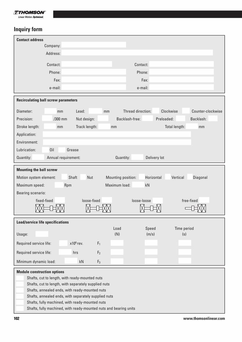
www.thomsonlinear.com102102
Module construction options Shafts, cut to length, with ready-mounted nuts Shafts, cut to length, with separately supplied nuts Shafts, annealed ends, with ready-mounted nuts Shafts, annealed ends, with separately supplied nuts Shafts, fully machined, with ready-mounted nuts Shafts, fully machined, with ready-mounted nuts and bearing units
Company:
Address:
Contact: Contact:
Phone: Phone:
Fax: Fax:
e-mail: e-mail:
Contact address
Recirculating ball screw parameters
Diameter: mm Lead: mm Thread direction: Clockwise Counter-clockwise
Precision: /300 mm Nut design: Backlash-free: Preloaded: Backlash:
Stroke length: mm Track length: mm Total length: mm
Application:
Environment:
Lubrication: Oil Grease
Quantity: Annual requirement: Quantity: Delivery lot
Mounting the ball screw
Motion system element: Shaft Nut Mounting position: Horizontal Vertical Diagonal
Maximum speed: Rpm Maximum load: kN
Bearing scenario:
fixed-fixed loose-fixed loose-loose free-fixed
Load/service life specifications
Usage: %
Required service life: x106 rev .
Required service life: hrs
Minimum dynamic load: kN
Load Speed Time period (N) (m/s) (s)
F1
F2
F3
Inquiry form
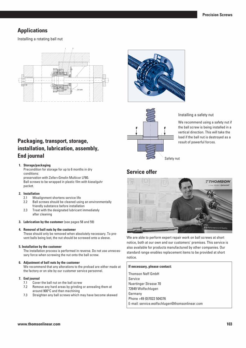
www.thomsonlinear.com 103
Precision Screws
Applications
1 2
Ölbad
Safety nut
Installing a rotating ball nut
1. Storage/packaging Precondition for storage for up to 6 months in dry
conditions: preservation with Zeller+Gmelin Multicor LF80. Ball screws to be wrapped in plastic film with kieselguhr packet.
2. Installation 2.1 Misalignment shortens service life 2.2 Ball screws should be cleaned using an environmentally
friendly substance before installation 2.3 Treat with the designated lubricant immediately after cleaning
3. Lubrication by the customer (see pages 58 and 59)
4. Removal of ball nuts by the customer These should only be removed when absolutely necessary. To pre-
vent balls being lost, the nut should be screwed onto a sleeve.
5. Installation by the customer The installation process is performed in reverse. Do not use unneces-
sary force when screwing the nut onto the ball screw.
6. Adjustment of ball nuts by the customer We recommend that any alterations to the preload are either made at
the factory or on site by our customer service personnel.
7. End journal 7.1 Cover the ball nut on the ball screw 7.2 Remove any hard areas by grinding or annealing them at
around 900°C and then machining 7.3 Straighten any ball screws which may have become skewed
Installing a safety nut
We recommend using a safety nut if the ball screw is being installed in a vertical direction. This will take the load if the ball nut is destroyed as a result of powerful forces.
We are able to perform expert repair work on ball screws at short notice, both at our own and our customers' premises. This service is also available for products manufactured by other companies. Our standard range enables replacement items to be provided at short notice.
If necessary, please contact:
Thomson Neff GmbHServiceNuertinger Strasse 7072649 WolfschlugenGermanyPhone +49 (0)7022 504376E-mail: [email protected]
Service offer
Packaging, transport, storage, installation, lubrication, assembly,End journal
Oil bath
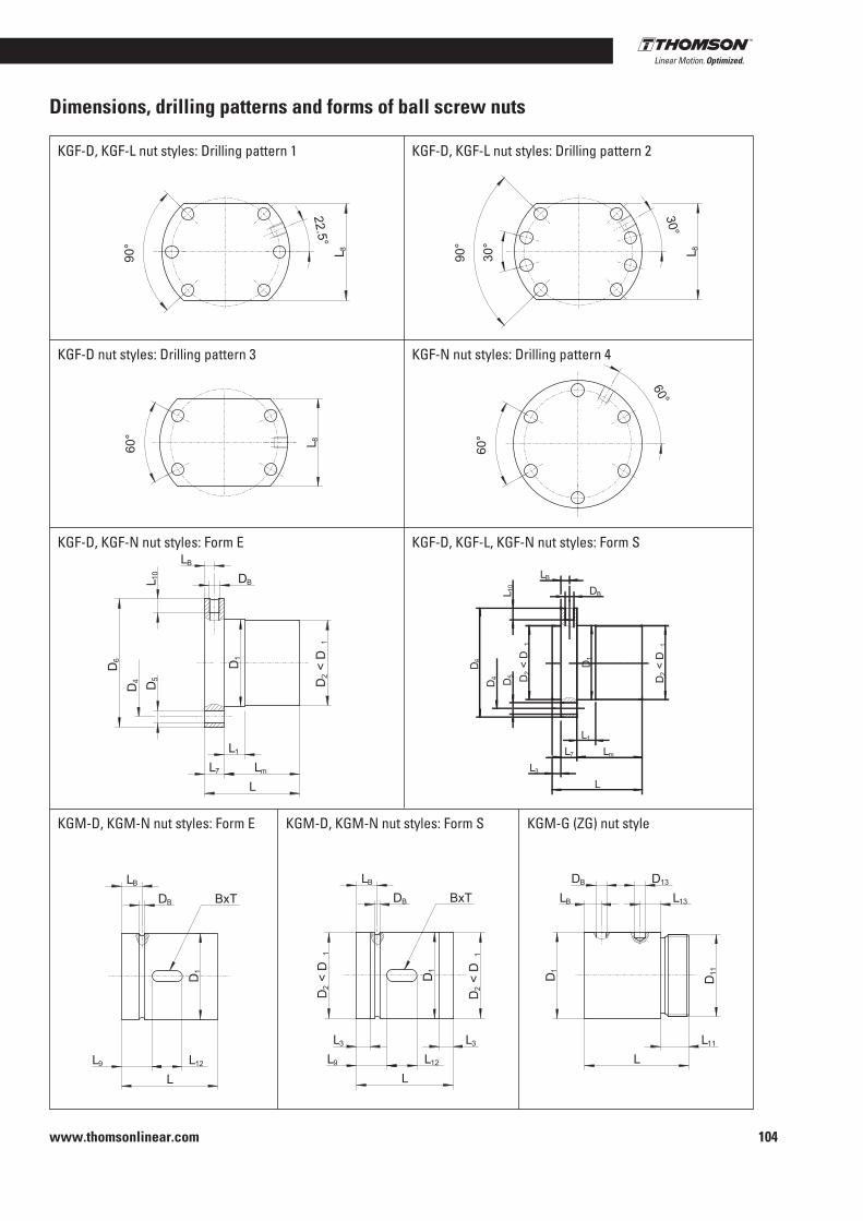
104www.thomsonlinear.com
Dimensions, drilling patterns and forms of ball screw nuts
L 8
22.5°
°09 L 8
30°
°09
°03
L 8
°06
60°
°06
L
L7
LB
DB
L1
Lm
D4 D5
D6
L 10
D2 <
D1
D1
L
L7
LB
DB
L1
Lm
D4 D5
D6
L 10
D2 <
D1
D1
L3
D2 <
D1
BxT
L12L9
L
D1
DB
LB
BxT
L12L9
L
D2 <
D1
D1
L3
D2 <
D1
DB
LB
L3
L
D11
LB
L11
L13
DB
D1
D13
KGF-D, KGF-L nut styles: Drilling pattern 1
KGF-D nut styles: Drilling pattern 3
KGF-D, KGF-N nut styles: Form E
KGM-D, KGM-N nut styles: Form E KGM-D, KGM-N nut styles: Form S KGM-G (ZG) nut style
KGF-D, KGF-L nut styles: Drilling pattern 2
KGF-N nut styles: Drilling pattern 4
KGF-D, KGF-L, KGF-N nut styles: Form S

www.thomsonlinear.com
Notes
Precision Screws

August 2014
www.thomsonlinear.comPrecision_Ball_Screws_CTUK-0004-02A | 20140815 SKSpecifications are subject to change without notice. It is the responsibility of the product user to determine the suitability of this product for a specific application. All trademarks property of their respective owners. © Thomson Industries, Inc. 2013
Precision Screws
EUROPEUnited KingdomThomsonPhone: +44 (0) 1271 334 500Fax: +44 (0) 1271 334 501E-mail: [email protected]
GermanyThomsonNürtinger Straße 7072649 WolfschlugenPhone: +49 (0) 7022 504 0Fax: +49 (0) 7022 504 405E-mail: [email protected]
FranceThomsonPhone: +33 (0) 243 50 03 30Fax: +33 (0) 243 50 03 39E-mail: [email protected]
ItalyThomsonLargo Brughetti20030 Bovisio MasciagoPhone: +39 0362 594260Fax: +39 0362 594263E-mail: [email protected]
SpainThomsonRbla Badal, 29-31 7th, 1st08014 BarcelonaPhone: +34 (0) 9329 80278Fax: + 34 (0) 9329 80278E-mail: [email protected]
SwedenThomsonEstridsväg 1029109 KristianstadPhone: +46 (0) 44 24 67 00Fax: +46 (0) 44 24 40 85E-mail: [email protected]
SOUTH AMERICA Thomson Sao Paulo, SP Brazil Phone: +55 11 3879-6600 Fax: +55 11 3879 6656 E-mail: [email protected]
USA, CANADA and MEXICO Thomson 203A West Rock RoadRadford, VA 24141, USAPhone: 1-540-633-3549Fax: 1-540-633-0294E-mail: [email protected]: literature.thomsonlinear.com
ASIAAsia PacificThomson750, Oasis, Chai Chee Road,#03-20, Technopark @ Chai Chee,Singapore 469000E-mail: [email protected]
ChinaThomsonRm 2205, Scitech Tower22 Jianguomen Wai StreetBeijing 100004Phone: +86 400 6661 802Fax: +86 10 6515 0263E-mail: [email protected]
IndiaThomson1001, Sigma Building Hiranandani Business Park Powai , Mumbai – 400076 Phone: +91 22 422 70 300 Fax: +91 22 422 70 338E-mail: [email protected]
JapanThomsonMinami-Kaneden 2-12-23, SuitaOsaka 564-0044 JapanPhone: +81-6-6386-8001Fax: +81-6-6386-5022E-mail: [email protected]
KoreaThomsonF12 Ilsong Bldg, 157-37Samsung-dong, Kangnam-gu,Seoul, Korea (135-090)Phone: +82 2 6917 5049Fax: +82 2 6917 5007E-mail: [email protected]


