PRE-STRESSED LINTELS CONCRETE CILLS STEPS COPES...
8
PRE-STRESSED LINTELS CONCRETE CILLS STEPS COPES EDGING T-BEAM FLOORING
Transcript of PRE-STRESSED LINTELS CONCRETE CILLS STEPS COPES...

PRE-STRESSED LINTELS
CONCRETE CILLS
STEPS
COPES
EDGING
T-BEAM FLOORING

TYPE A (100 X 70mm) Permissable U.D.L. in kN/m per layer of brickwork 50m/ton
CLEAR SPAN (mm) 600 900 1200 1500 1800 2100 2400 2800 3100
Without Brickwork 9.00 6.37 3.86 2.58 1.85 1.39 1.08 - -
1 Layer of Brickwork 10.50 9.00 7.01 5.00 2.75 1.62 1.31 - -
2 Layers 12.00 10.21 10.21 8.00 4.38 2.75 1.46 1.35 1.31
3 Layers 16.25 16.25 16.25 9.37 5.75 4.44 2.50 2.25 2.00
5 Layers 30.00 30.00 30.00 15.37 12.00 8.00 4.75 4.50 4.25
TYPE B (150 X 70mm) Permissable U.D.L. in kN/m per layer of brickwork 36m/ton
CLEAR SPAN (mm) 600 900 1200 1500 1800 2100 2400 2800 3100
Without Brickwork 10.00 7.24 4.49 3.01 2.15 1.62 1.26 - -
1 Layer of Brickwork 13.61 13.61 9.26 6.50 3.02 2.31 1.81 - -
2 Layers 28.00 28.00 10.26 8.25 5.00 3.30 2.78 1.71 1.44
3 Layers 29.50 29.50 25.00 10.00 6.00 4.66 3.98 2.60 2.19
5 Layers 32.00 32.00 30.00 16.50 13.00 9.15 8.00 5.00 4.75
COMPOSITE LINTELS
Composite lintels, Type A and Type B, are best used in conjunction with brickwork or blockwork - see tables for loadbearing capacities.
1. It is essential that the first two layers of brickwork, or one layer of blockwork, are laid with special care and that the mortar joints both vertical and horizontal are properly
filled, leaving no voids. (1:3 cement, sand mortar is recommended).
2. Building blocks may be used if they are solid and have a minimum crushing strength of 3.0N/mm2.
3. In lintels over 1.500m props must be used at the quarter points until mortar work has matured.
4. Where a D.P.C. is used it must be placed over the second layer of the blockwork - see sketch detail.
5. Minimum bearing of 150mm each side, or as directed by the structural engineer.
LinteL ArrAngement ForCAvity WALL
LinteL in SingLe WALL LinteL in BLoCkWork PiPeS And ServiCeS PAdStoneS (rSj or uB)tyPiCAL CAvity WALL detAiL
CONCRETE
ROBESLEE
CONCRETE LINTELS
CAN BE MADE
TO ARCHITECTS
PRECISE
SPECIFICATIONS

NON COMPOSITE LINTELS Permissable U.D.L. in kN/m
CLEAR SPAN (mm) 900 1200 1500 1800 2100 2400 2700 3000 3300 3600 3900
TYPE C (100 X 145mm) 27m/ton 32.60 23.30 18.10 13.90 10.50 8.15 6.53 5.34 4.39 3.42 2.71
TYPE D (145 X 100mm) 27m/ton 30.10 20.00 13.40 9.58 7.20 5.17 3.70 2.74 2.09 1.62 1.29
TYPE E (100 X 100mm) 38m/ton 13.00 7.88 5.27 3.78 2.84 2.21 1.77 1.05 - - -
TYPE F (145 X 145mm) 18m/ton 41.60 29.80 22.70 16.20 12.20 9.49 7.59 6.22 5.18 4.39 3.19
TYPE K9 (100 X 215mm) 18m/ton 54.70 38.10 29.20 23.70 19.90 17.20 14.70 12.10 10.00 8.51 7.29
TYPE G8 (140X 215mm) 14m/ton 64.10 56.80 44.67 32.18 24.95 19.58 15.91 13.04 10.42 8.79 7.57
TYPE U2 (100 X 145mm) 27m/ton 31.20 21.20 14.20 10.20 7.65 5.95 4.77 3.90 - - -
TYPE U2 (145 X 100mm) 27m/ton 23.40 14.20 9.48 6.79 5.10 3.97 3.18 2.60 - - -
These lintels are designed to withstand direct imposed loads. Rafters, wall plates and floor joists may be accommodated as directly imposed loads -see tables for loadbearing capacities.
BEARING: Minimum of 150mm each side or as directed by the structural engineer. PROPPING: Propping is not required with this type of lintel.
BRICKWORK: Non-composite lintels do not require brickwork bonded to them. POSITIONING: Lintels must be placed with wire in correct position.
Point loads from girders, trusses, steel beams ect. require to be referred Lintels are marked top.
to our Customer Advisory Service. ORDERING: All sizes listed are normal stock sizes.
All lintels are designed in accordance with -BS 5977: Part 1: 1981, BS 5977: Part 2: 1983, BS 8110: Part 1: 1985, BS 8110: Part 2:
Concrete used is Grade 50. Fire resistance is 1/2 hour. Fire resistance can be improved by the application of non-combustible finishes.
The evolution of new designs is continuous, and information is subject to change without notice. Customers should check with the supplier to ensure that they have the latest details. No liability or responsibility of any kind (including liability for negligence ) is accepted in respect of advice, recommendations or specifications supplied by the company, its Servants or its Agents.
BeAring direCt LoAdS, SuCh AS joiStS
CONCRETE LINTELS
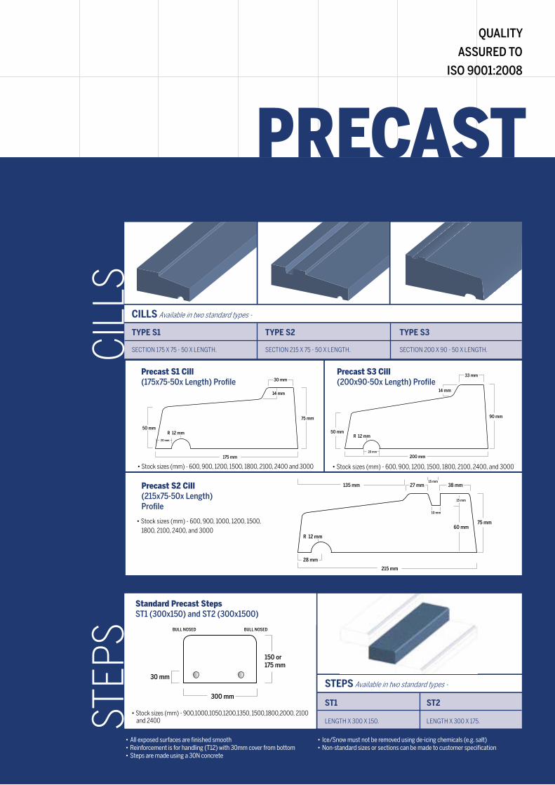
FLOORINGCILLS Available in two standard types -
TYPE S1 TYPE S2 TYPE S3
SECTION 175 X 75 - 50 X LENGTH. SECTION 215 X 75 - 50 X LENGTH. SECTION 200 X 90 - 50 X LENGTH.
50 mmR 12 mm
20 mm
75 mm
175 mm
30 mm
14 mm
38 mm27 mm
10 mm
15 mm
15 mm135 mm
R 12 mm
215 mm
28 mm
75 mm60 mm
Precast S1 Cill (175x75-50x Length) Profile
• Stock sizes (mm) - 600, 900, 1200, 1500, 1800, 2100, 2400 and 3000
CIL
LS
STEPS Available in two standard types -
ST1 ST2
LENGTH X 300 X 150. LENGTH X 300 X 175.
300 mm
150 or175 mm
30 mm
BULL NOSED BULL NOSED
• All exposed surfaces are finished smooth • Reinforcement is for handling (T12) with 30mm cover from bottom • Steps are made using a 30N concrete
STEP
S
Standard Precast Steps ST1 (300x150) and ST2 (300x1500)
PRECAST
QUALITY
ASSURED TO
ISO 9001:2008
• Ice/Snow must not be removed using de-icing chemicals (e.g. salt) • Non-standard sizes or sections can be made to customer specification
R 12 mm
33 mm
14 mm
90 mm
200 mm20 mm
50 mm
Precast S2 Cill (215x75-50x Length) Profile
• Stock sizes (mm) - 600, 900, 1000, 1200, 1500, 1800, 2100, 2400, and 3000
• Stock sizes (mm) - 600, 900, 1200, 1500, 1800, 2100, 2400, and 3000
Precast S3 Cill (200x90-50x Length) Profile
• Stock sizes (mm) - 900,1000,1050,1200,1350, 1500,1800,2000, 2100 and 2400
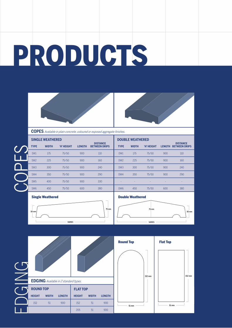
FLOORINGCOPES Available in plain concrete, coloured or exposed aggregate finishes.
75 mm50 mm
VARIES
COPE
S
VARIES
75 mm50 mm
EDGING Available in 2 standard types.
ROUND TOP
EDG
ING
HEIGHT WIDTH LENGTH
152 51 900
FLAT TOP
HEIGHT WIDTH LENGTH
152 51 900
205 51 900
152 mm
51 mm
152 mm
51 mm
Round Top Flat Top
PRECAST PRODUCTS
Single Weathered Double Weathered
SINGLE WEATHERED
COPE
S TYPE WIDTH ‘H’ HEIGHT LENGTH BETWEEN DRIPS
SW1 175 75/50 900 110
SW2 225 75/50 900 160
SW3 300 75/50 900 240
SW4 350 75/50 900 290
SW5 400 75/50 900 330
SW6 450 75/50 600 380
TYPE WIDTH ‘H’ HEIGHT LENGTH BETWEEN DRIPS
DW1 175 75/50 900 110
DW2 225 75/50 900 160
DW3 300 75/50 900 240
DW4 350 75/50 900 290
- - - - -
DW6 450 75/50 600 380
DOUBLE WEATHERED DISTANCE DISTANCE

T-BEAMSTANDARD CENTRES SECTIONS Maximum Spans (m) for imposed load kN/m2
1.5 2.0 2.5 3.0 5.0 7.0
SINGLE 520 (1.8kN/m 2) 4.40 4.10 3.90 3.80 3.20 2.80
SINGLE 408 (1.9kN/m 2) 4.90 4.60 4.40 4.20 3.60 3.20
SINGLE 295 (2.2kN/m 2) 5.60 5.30 5.10 4.90 4.20 3.80
DOUBLE 644 (2.2kN/m 2) 5.40 5.10 4.90 4.70 4.10 3.60
DOUBLE 532 (2.4kN/m 2) 5.80 5.60 5.30 5.10 4.40 4.00
DOUBLE 420 (2.7kN/m2) 6.00 6.00 5.90 5.60 4.90 4.40
TREBLE 770 (2.5kN/m2) 5.90 5.60 5.40 5.20 4.50 4.00
TREBLE 658 (3.0kN/m 2) 6.00 6.00 5.80 5.50 4.80 4.30
T-BEAM FLOORS
440 440
520
440
408
215
215
295
215
440
644
440
440
532
215
420
215215
770
440 440
658
215 215
440 440
520
440
408
215
215
295
215
440
644
440
440
532
215
420
215215
770
440 440
658
215 215
440 440
520
440
408
215
215
295
215
440
644
440
440
532
215
420
215215
770
440 440
658
215 215
440 440
520
440
408
215
215
295
215
440
644
440
440
532
215
420
215215
770
440 440
658
215 215
440 440
520
440
408
215
215
295
215
440
644
440
440
532
215
420
215215
770
440 440
658
215 215
440 440
520
440
408
215
215
295
215
440
644
440
440
532
215
420
215215
770
440 440
658
215 215
440 440
520
440
408
215
215
295
215
440
644
440
440
532
215
420
215215
770
440 440
658
215 215
440 440
520
440
408
215
215
295
215
440
644
440
440
532
215
420
215215
770
440 440
658
215 215
The above table shows maximum clear spans in metres for the Robeslee T42 Floor Beam (120x150) under uniformly distributed live loads using 1350 kg/m3 solid blocks. An allowance of 1.20 kN/m2 for finishes has been made when calculating the table.
80mm
120mm
150mm
50mm
HIGH STRENGTH,
EFFECTIVE
AND EASY TO INSTALL
FLOORING SYSTEM

FLOORINGT - BEAM Illustration
TECHNICAL INFORMATIONThe T42 Floor Beam, combines concrete beams and infill blocks to provide a highly effective and easy to install flooring system.
The T42 Beam is nominally 150 deep and weighs 40kg/m. It is manufactured using concrete with a strength of 50 N/mm2.
INFILL BLOCKSInfill blocks can be any standard building blocks (440x215x100) complying with BS6073:Part 1-1981. They must have a minimum density of 1350 kg/m3 and have 3.5 N/mm2 - minimum strength. For increased sound resistance we recommend using blocks with a density of 1800 kg/m3.
BEARINGSAll beams should be placed perpendicular to the end supports unless otherwise shown. Each beam requires a minimum end bearing of 100mm to each end when supported by brickwork/blockwork and 75mm when supported by steelwork.
GROUTING A 3:1 sand:cement should be brushed into the joints between the beams and the blocks.
FLOOR FINISHESWhen laid the floor can take a wide variety of finishes. We would recommend the use of a sand:cement levelling screed before the application of final finishes. Garage floors require a 50mm concrete screed using a Grade 25 concrete and suitable reinforcement.
CUT BLOCKSAll blocks are to be cut using suitable mechanical means to leave a clean, vertical square edged face.
SLIP BLOCKSSlip Blocks 440 x 100x 40 (nominal) are used around the perimeter of the floor to make up the difference in level between the underside of the blocks.
SERVICE HOLESInfill blocks may be omitted as necessary to accommodate services.
AIR VENTSVoid ventilators are required by the NHBC and the spacings may vary. Please consult vent manufacturers for details and supply.
HANDLINGCare should be taken to ensure all beams are lifted horizontally. Beams should not be lifted upside down or allowed to rotate while being handled.
CAMBERAs the beams are made from prestressed concrete they have slight upward camber. Due allowance must be made for this in determining finishes an overall floor thickness.
The T42 Floor beam has been designed using our ‘STAR’ technology system (in accordance with BS 5977 Part 1: 1981 and Part 2: 1983 and BS 8110 Part 1: 1985 and Part 2: 1985) and is manufactured using an advanced extrusion method at our factory in Kirkintilloch.
The T42 Floor beam can be made to any required length up to 6 metres within given limits.
Robeslee offer a free technical and computer aided design service (telephone 0141 775 2677) to assist you in the use of the T42 Floor Beam. The service provides comprehensive details of floor layouts, working drawings and quantity requirements.
Slip blocks or split courseunder infill block at walls
Block cut to suit
Split course bybuilder
100mm block
Prestressed beam
DPC by builder
Non-loadbearing wallsbuilt off floor
Additional beams belowwalls depending upon spans etc.
Support wall
DPC
Beams overlap on 100mmsupport walls
Main loadbearing walls built over support walls

NATIONWIDE COVERAGE
THROUGH OUR
TRANSPORT FLEET
& LEADING
BUILDERS MERCHANTS
ROBESLEE CONCRETE COMPANY LTD.
SOUTHBANK ROAD, KIRKINTILLOCH,
GLASGOW G66 1UA
T_ 0141 775 2677
F_ 0141 777 8120
WWW.ROBESLEE.CO.UK


![Untitled-2 []2.00 4.00 Help Miles 12.00 15.00 12.00 20.00 12.00 My Dashboard $25.00 Edit/ View $30.00 Edit 'View $20.00 Edit 'View $30.00 Echt/View $30.00 Ecfit/View Logout Case JD](https://static.fdocuments.net/doc/165x107/5f2be5c6b977734cf21d1279/untitled-2-200-400-help-miles-1200-1500-1200-2000-1200-my-dashboard-2500.jpg)