PRE-INSTALLATION INFORMATION AND CHECKLIST (SG5…€¦ · Installation area ... Static loads...
23
PRE-INSTALLATION INFORMATION AND CHECKLIST (SG5/SG6) With Sinumerik 840D or Fanuc 16P control Edition 2.0/1999-07-30/GB
Transcript of PRE-INSTALLATION INFORMATION AND CHECKLIST (SG5…€¦ · Installation area ... Static loads...

PRE-INSTALLATION INFORMATION AND CHECKLIST (SG5/SG6) With Sinumerik 840D or Fanuc 16P control Edition 2.0/1999-07-30/GB

2.0/1999-07-30/GB
FINN-POWER Lillbacka Corporation Pre-Installation information and checklist for SG5/SG6 with Sinumerik 840D or Fanuc 16P control 2
Dear Finn-Power Turret Punch Press Customer, to ensure that the installation of the turret punch press will progress smoothly and without delay, we would kindly ask you to familiarise yourselves with these instructions. Please fill in carefully the checklist on the following page and send or fax the following documents to your Finn-Power Dealer not later than five weeks before the given delivery time: 1 Completed and signed checklist 2 Signed layout 3 Completed enc. 2 The Dealer must have received these documents before the installation of the turret punch press can start.
2.0/1999-07-30/GB
FINN-POWER Lillbacka Corporation Pre-Installation information and checklist for SG5/SG6 with Sinumerik 840D or Fanuc 16P control 3
CHECKLIST Customer name: ___________________________________________________ Address: ___________________________________________________ ___________________________________________________ Phone: ___________________________________________________ Fax : ___________________________________________________ Contact person: ___________________________________________________ The Customer answers for the following items: 1 Installation site is empty before the delivery arrives (see system layout). 2 Floor flatness and load capacity as well as other conditions on the installation
site have been checked (see item 1). 3 Hoisting equipment for unloading the lorries is available and the transport
routes for the goods are checked (see item 2). 4 Power and compressed air supplies are ready (see item 3). 5 Programming unit and data transfer connection are ready (see items 4 and 5).
Operators are familiarised with Microsoft operating systems and have basic knowledge about computer systems.
6 Hydraulic oil is available (see item 6). 7 Crane and/or forklift truck is available during the installation (see item 7). 8 Tools and accessories listed in these instructions are available (see item 7). 9 Telephone line is available 10 Punching tools are available on ______________________ Please write date 11 Raw materials are available (see item 8) 12 Programming and operating training has been completed on ______________________ Please write date 13 Part programs prepared to test the equipment (see item 8) . _________________________ ___________________________ Time and place Signature ___________________________ Name and position in block letters
2.0/1999-07-30/GB
FINN-POWER Lillbacka Corporation Pre-Installation information and checklist for SG5/SG6 with Sinumerik 840D or Fanuc 16P control 4
CONTENTS 1. Floor and other conditions on installation site ................................................... 6
1.1. Requirements on floor............................................................................................... 6 1.1.1. Floor description............................................................................................. 6 1.1.2. Floor flatness.................................................................................................. 6 1.1.3. Installation area .............................................................................................. 6 1.1.4. Density ........................................................................................................... 6
1.2. Operation environment.............................................................................................. 6 2. Receiving the delivery ........................................................................................... 6
2.1. Transport routes and order ....................................................................................... 7 2.2. Hoisting the punch press and right angle shear ........................................................ 7 2.3. Hoisting the control unit............................................................................................. 7 2.4. Hoisting the hydraulic unit ......................................................................................... 7 2.5. Insurance .................................................................................................................. 7 2.6. Hoisting points of turret punch press......................................................................... 8 2.7. Hoisting points of right angle shear ........................................................................... 8 2.8. Storing....................................................................................................................... 8
3. Power and compressed air supplies..................................................................... 9 3.1. Supply voltage .......................................................................................................... 9 3.2. Power supply ............................................................................................................ 9 3.3. Phase order ............................................................................................................ 10 3.4. Power supply for CS storage .................................................................................. 10 3.5. Use of a leakage current switch .............................................................................. 10 3.6. Compressed air supply (P1).................................................................................... 10
4. Programming computer and data transfer connection ..................................... 12 4.1. PowerLink MMC (option) ...................................................................................... 12
4.2. Description of PowerLink MMC for SG 5/SG6 delivery ........................................... 12 4.3. Jetcam computer and software (option) .................................................................. 12
4.3.1. Jetcam software ........................................................................................... 12 4.3.2. Power to Programming Computer Station (Jetcam) ..................................... 12 4.3.3. Hardware requirements for Jetcam: ............................................................. 12
5. Networking the computers ..................................................................................... 14 5.1. Network software .................................................................................................... 14 5.2. Network hardware................................................................................................... 14
5.2.1. Network adapter cards ................................................................................. 14 5.2.2. Network cable............................................................................................... 14 5.2.3. Switching hub concentrator item 2................................................................ 15 5.2.4. Wall socket RJ-45......................................................................................... 15
6. Hydraulic oil .......................................................................................................... 16 6.1. General ................................................................................................................... 16
6.1.1. Filling up the oil tank..................................................................................... 17 7. Installation ............................................................................................................. 19
7.1. Equipment and tools required ................................................................................. 19 7.2. Assisting personnel ................................................................................................. 19 7.3. Telephone connection............................................................................................. 19
8. Preparations for system start-up......................................................................... 20

2.0/1999-07-30/GB
FINN-POWER Lillbacka Corporation Pre-Installation information and checklist for SG5/SG6 with Sinumerik 840D or Fanuc 16P control 5
8.1. Test programs......................................................................................................... 20 8.2. Punching tools ........................................................................................................ 20 8.3. Raw materials ......................................................................................................... 20

2.0/1999-07-30/GB
FINN-POWER Lillbacka Corporation Pre-Installation information and checklist for SG5/SG6 with Sinumerik 840D or Fanuc 16P control 6
1. Floor and other conditions on installation site 1.1. Requirements on floor
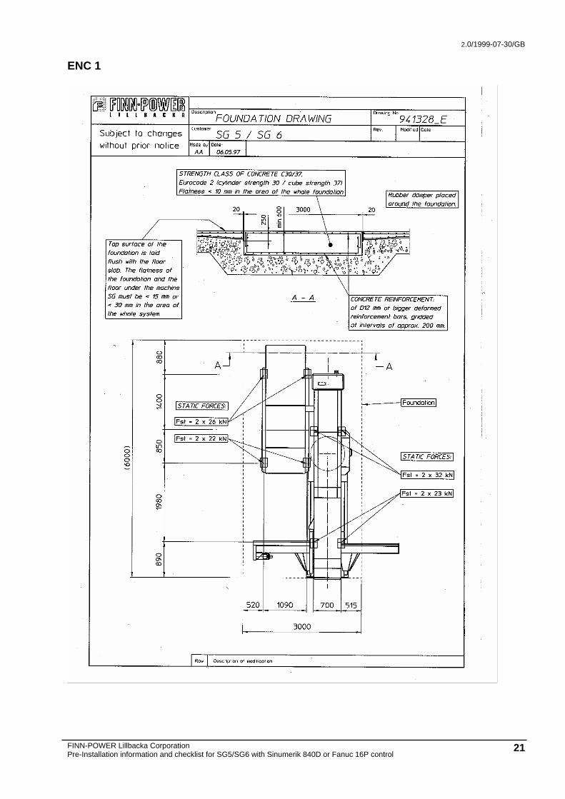
Static loads caused by the equipment (Fst) are marked in the installation / load diagram (Enc. 1). Prior to the installation, ensure the floor's load capacity within the area of the whole equipment. When required, a single foundation must be laid for the machine (see foundation drawing). Use a building specialist to estimate the floor's load capacity if necessary. The turret punch press and the right angle shear must locate on the same concrete floor tile.
1.1.1. Floor description Concrete slab • Strength class of concrete C30/37, Eurocode 2 • minimum thickness 200 mm
1.1.2. Floor flatness Floor flatness must be <15 mm under the machine feet and <30 mm elsewhere in the system.
1.1.3. Installation area No joints within the machine area
1.1.4. Density Surface of concrete has to be oilproof.
1.2. Operation environment The machine must be installed in a dry and dust-free space with even temperature. There must not be any machines or equipment generating vibration nearby, or precautions must be taken to isolate the machine from outside vibration sources. Temperature range allowed +15°C ... +30°C (59°F ...86°F) (Siemens 880N/840D) Temperature range allowed +15°C ... +38°C (59°F ...100°F) (Fanuc 16P) Relative air humidity 20 %...75 %, temporary max. 90 % With an optional cooler installed in the servo cabinet, max. +38°C (100°F) ambient temperature is allowed. With Fanuc 16P the cooler is not needed. The accuracy specified in the LKP-7100 standard is guaranteed within temperatures +17°C ... +23°C (63°F ... 73°F).
2. Receiving the delivery The Customer is totally responsible for unloading and transferring the goods from lorry or container to installation site. In general, the turret punch press and
2.0/1999-07-30/GB
FINN-POWER Lillbacka Corporation Pre-Installation information and checklist for SG5/SG6 with Sinumerik 840D or Fanuc 16P control 7
right angle shear are unloaded from the trailer lorry by an autocrane. On the shop floor, they can be moved by transportation rollers or a factory crane if the autocrane is too big to be used inside the factory building.
2.1. Transport routes and order The machine needs 2.3 m of free space in horizontal and 2.2 m in vertical direction. Examine carefully the load carrying capacity of both the floor and hoisting and transportation equipment. Kindly specify, together with representatives of the FP sales organisation, the order in which goods are to be delivered to the installation site. Fill in enclosure 2 and return it to the FP representative.
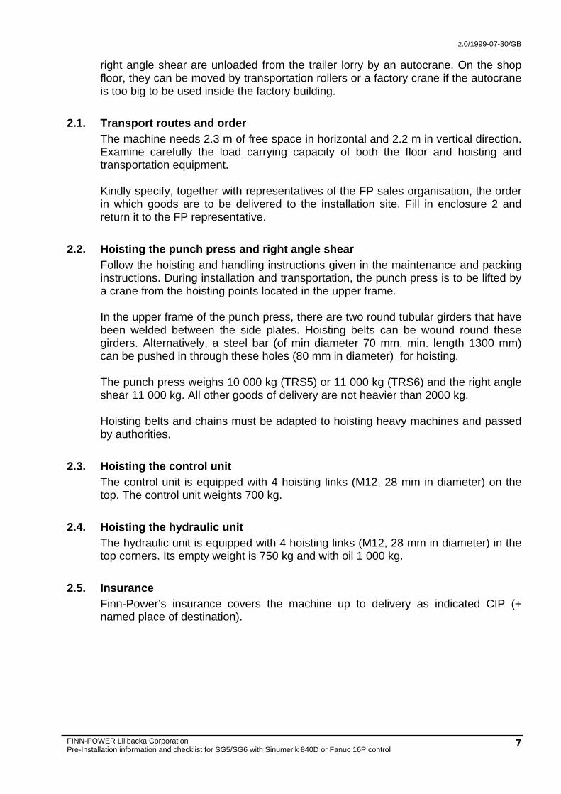
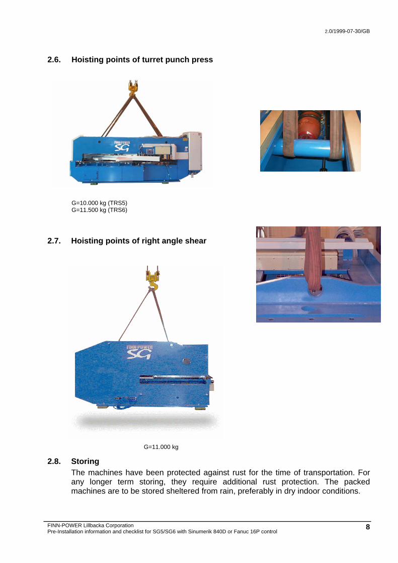
2.2. Hoisting the punch press and right angle shear Follow the hoisting and handling instructions given in the maintenance and packing instructions. During installation and transportation, the punch press is to be lifted by a crane from the hoisting points located in the upper frame. In the upper frame of the punch press, there are two round tubular girders that have been welded between the side plates. Hoisting belts can be wound round these girders. Alternatively, a steel bar (of min diameter 70 mm, min. length 1300 mm) can be pushed in through these holes (80 mm in diameter) for hoisting. The punch press weighs 10 000 kg (TRS5) or 11 000 kg (TRS6) and the right angle shear 11 000 kg. All other goods of delivery are not heavier than 2000 kg. Hoisting belts and chains must be adapted to hoisting heavy machines and passed by authorities.
2.3. Hoisting the control unit The control unit is equipped with 4 hoisting links (M12, 28 mm in diameter) on the top. The control unit weights 700 kg.
2.4. Hoisting the hydraulic unit The hydraulic unit is equipped with 4 hoisting links (M12, 28 mm in diameter) in the top corners. Its empty weight is 750 kg and with oil 1 000 kg.
2.5. Insurance Finn-Power’s insurance covers the machine up to delivery as indicated CIP (+ named place of destination).
2.0/1999-07-30/GB
FINN-POWER Lillbacka Corporation Pre-Installation information and checklist for SG5/SG6 with Sinumerik 840D or Fanuc 16P control 8
2.6. Hoisting points of turret punch press
G=10.000 kg (TRS5) G=11.500 kg (TRS6)
2.7. Hoisting points of right angle shear
G=11.000 kg
2.8. Storing The machines have been protected against rust for the time of transportation. For any longer term storing, they require additional rust protection. The packed machines are to be stored sheltered from rain, preferably in dry indoor conditions.

2.0/1999-07-30/GB
FINN-POWER Lillbacka Corporation Pre-Installation information and checklist for SG5/SG6 with Sinumerik 840D or Fanuc 16P control 9
3. Power and compressed air supplies The Customer is responsible for connecting the system to the factory's power and compressed air supplies.
3.1. Supply voltage Supply voltage required by the machine: 3 x 400 V and PE Supply voltage frequency: 50 Hz or 60 Hz Supply voltage fluctuation: max. +/- 7 % If the supply voltage at the Customer deviates from the voltage mentioned above, an auto-transformer is needed to convert the supply voltage into 400 VAC. With the auto-transformer (75 kVA, 50/60 Hz, 3~+PE) delivered by Finn-Power, the following voltages can be converted into 400 VAC: 200V, 208V, 220V, 230V, 380V, 415V, 440V and 460V.
3.2. Power supply Cables and front fuses must be selected in accordance with the electrical safety regulations valid in the country concerned. Sizes of cables cross-sections and fuses given in this document are based on EN and IEC regulations. A machine without auto-transformer has to be equipped with a fast front fuse. The front fuse and cable size for PVC-insulated copper cable in mounting method E when mounting one 3-phase cable loaded with alternating current in the cable rack in + 40°C ambient temperature. Supply voltage Supply cable Front fuse 3 x 400 V 4 x 35 mm2 3 x 100 A A machine with auto-transformer has to be equipped with fast front fuses according to specifications below. It describes the front fuse and cable sizes for PVC-insulated copper cable in mounting method E when mounting one 3-phase cable loaded with alternating current in the cable rack in + 40°C (200V, +30°C) ambient temperature. The machine can be protected by cables and front fuses of smaller size, given in parentheses below, but the protection will no longer be selective. However, we recommend a selective protection. Voltage Supply cable Front fuse 200 V 4 x (95) 95 mm2 (160 A) 200 A (+ 30 °C) 208 V 4 x (95) 95 mm2 (160 A) 200 A (+ 30 °C) 220 V 4 x (95) 95 mm2 (160 A) 200 A (+ 30 °C) 230 V 4 x (95) 95 mm2 (160 A) 200 A (+ 30 °C) 380 V 4 x (35) 70 mm2 (100 A) 125 A 415 V 4 x (25) 35 mm2 (80 A) 100 A 440 V 4 x (25) 35 mm2 (80 A) 100 A

2.0/1999-07-30/GB
FINN-POWER Lillbacka Corporation Pre-Installation information and checklist for SG5/SG6 with Sinumerik 840D or Fanuc 16P control 10
460 V 4 x (25) 35 mm2 (80 A) 100 A Cable between auto-transformer and equipment: 4 x 35 mm2. The connectors for the power supply of the transformer are intended for connecting copper cables only.
3.3. Phase order The phase order must be correct. If it is wrong, the motor of the hydraulic unit will rotate in the wrong direction and the hydraulic system will not work. Correct by interchanging any two phases at the main switch.
3.4. Power supply for CS storage The CS storage needs its own separate power supply as follows;
without auto-transformer
Supply voltage Supply cable Front fuse
3 x 400V 4 x 4mm2 3 x 20A
with auto-transformer
Supply voltage max Supply cable F1-F3
200V 43,3 A 4 x 10 mm2 40 A 208V 41,6 A 4 X 10 mm2 40 A 220V 39,4 A 4 X 10 mm2 35 A 230V 37,7 A 4 X 10 mm2 35 A 400V 21,6 A 4 X 4 mm2 20 A 415V 20,9 A 4 X 4 mm2 20 A
440V 19,7 A 4 X 4 mm2 20 A
460V 18,8 A 4 X 4 mm2 20 A 480V 18,0 A 4 X 4 mm2 20 A
3.5. Use of a leakage current switch We do not recommend to use a leakage current switch in the network before the power supply for the machine.
If the local law requires a leakage current switch, make sure - to use an electronic leakage current switch so that only the phase conductors and the neutral (if any) are taken through the sum current transformer (toroid). - that leakage current tripping limit is set at least at 500 mA. - that a tripping delay of ∼ 100 ms is set for leakage current tripping. Do not use electromechanical leakage current switches as they trigger false alarms.
3.6. Compressed air supply (P1) Compressed air supplies for all devices are gathered together by a connection block. There is a G1 IN nut thread in the block for the external supply (P1) to the
2.0/1999-07-30/GB
FINN-POWER Lillbacka Corporation Pre-Installation information and checklist for SG5/SG6 with Sinumerik 840D or Fanuc 16P control 11
compressed air supply system. The minimum inside diameter of the supply hose must be 25 mm (1 IN). The flexible connection hose of approx. 1 m included in the delivery is to be mounted between the pipework and connection block. The various devices have their own compressed air supply unit (shut-off valve, drop separator, filter, pressure regulator and pressure gauge) after the connection block as follows: load and unload device has a common unit, suction cup lifter and punch press have a unit each. The drop separators have an automatic emptying system. Compressed air consumption is given in atmospheric pressure. Minimum compressed air pressure is 6 bar. Filtration efficiency of compressed air must be 60 μm or better and the dew point under 5°C. Equipment Compressed air consumption max. SG 110 Nl/s SG+UD 125 Nl/s SG+C 1500+STS 110 Nl/s SG 64 125 Nl/s CS25*) 60 Nl/s (G3/4) CS30*) 80 Nl/s (G3/4) SGR**) 200NI/s In case more devices (eg a right angle shear or sorting units) are integrated into the system, all compressed air supplies can be made with the connection block which has additional outlet ports for this purpose. Air consumption of the optional devices must be considered in the total consumption of the supply (P1). *) The CS storage has its own separate compressed air connection. **) The SGR has its own separate compressed air connection.

2.0/1999-07-30/GB
FINN-POWER Lillbacka Corporation Pre-Installation information and checklist for SG5/SG6 with Sinumerik 840D or Fanuc 16P control 12
4. Programming computer and data transfer connection
4.1. PowerLink MMC (option) Items included: Hardware • Software • Operation systems Items excluded • Network software on customers side • Network cabling
4.2. Description of PowerLink MMC for SG 5/SG6 delivery PowerLink MMC computers comes with the operation systems, Powerlink MMC software application manager and network adapter installed. Delivery includes: • 3COM Etherlink XL PCI network adapter installed • Microsoft Windows NT 4.0 • Back-up tape with the contents of the hard disk
4.3. Jetcam computer and software (option) Normally the Jetcam software is delivered with each stand alone, especially when PowerLink is delivered. Those two computers should be connected to a network to enable fast and easy NC program transfer between the two computers. In most cases the Jetcam computer is separately purchased by the Customer and also connected to the Customer's main network to allow access to geometry files located in CAD computers.
4.3.1. Jetcam software Jetcam software delivery includes only software. When Jetcam software and hardware are included in the delivery, the delivery include 3Com Etherlink III Combo or XL PCI network adapter card for the Jetcam computer. Finn-Power training personnel can support the installation of network software in the Jetcam computer.
4.3.2. Power to Programming Computer Station (Jetcam) Duplex receptacle 220 VAC, 10 A, 50 Hz, single phase, dedicated circuit, isolated ground. Surge protection and uninterrupted power supply (UPS) is recommended.
4.3.3. Hardware requirements for Jetcam: Pentium, 300 MHz or better

2.0/1999-07-30/GB
FINN-POWER Lillbacka Corporation Pre-Installation information and checklist for SG5/SG6 with Sinumerik 840D or Fanuc 16P control 13
64 MB of RAM or more 500 MB hard disk or more 3 button mouse ( Logitech MouseMan ™) or any other pointing device two serial ports with 25-pin connector display 17’’ or larger Laser printer HP
NOTE! Please ensure that the personal involved to the machine is familiarised with Microsoft operating systems and have basic knowledge about computer systems.
2.0/1999-07-30/GB
FINN-POWER Lillbacka Corporation Pre-Installation information and checklist for SG5/SG6 with Sinumerik 840D or Fanuc 16P control 14
5. Networking the computers The Customer is totally responsible for the network cabling. Preferred topology is Ethernet with 10Base-T twisted pair cables according to Cat5 and Hewlett Packard J3200A stackable switching hub or similar.
5.1. Network software The recommended network software is Microsoft NT with NETBEUI protocal.
5.2. Network hardware Network hardware including cables, connectors, network adapter cards and switching hub can be purchased from FINN-POWER. It is however recommended to use a local network distributor.
The following components listed or similar are preferred.
5.2.1. Network adapter cards PowerLink terminal computer comes with the adapter card installed. The type of card used by Finn-Power is 3Com Etherlink XL PCI. An adapter card of the same type is delivered with Jetcam computer (if include in the delivery). Use of identical adapter cards simplifies installation and configuration of the network.
5.2.2. Network cable Finn-Power recommends Category 5 unshielded twisted pair cable (S-UTP), that meets 100 Mbit/s speed. Each computer is connected to the switching hub with a max. 100 m long cable. The computer end of the cable is connected to a RJ45 wall socket. The computer backplane is connected to the socket with a 1 m flexible RJ45 connection cable Network cable • Manufacturer LK-NES • Class ANSI/TIA/EIA-568-A CAT5 2*(4*2*24AWG). • Code 119Y7993 • Item: 7 Flexible connection cable, 1 m • Manufacturer LK-NES • Code 119Y8741 • Item 5
2.0/1999-07-30/GB
FINN-POWER Lillbacka Corporation Pre-Installation information and checklist for SG5/SG6 with Sinumerik 840D or Fanuc 16P control 15
5.2.3. Switching hub concentrator item 2 As the hub, Finn-Power recommends a switchable hub • Hewlett Packard 12-port HPJ3201A HP Advancestack 12R/SNMP with switching
module J3212A or • Hewlett Packard 12-port ProCurve Switch 212M (J3298A)
The hub can be installed in the control cabinet or in a dust-free cabinet. When specifying the location of the hub, observe that the maximum distance from computer backplane to the hub is 100 m cable length.
5.2.4. Wall socket RJ-45 The wall socket is mounted close to the computer. The 1 m long flexible connection cable (Item 5) is connected from computer backplane to the wall socket. Manufacturer LK-NES • Part code 510Y7050 washer • 510Y6080 wall socket • 510Y7662 assembly plate + connector • 510Y6000 cover • Item 3
When using these parts, no special tools are needed.
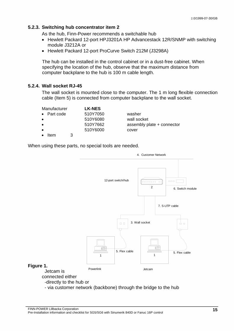
Figure 1. Jetcam is
connected either -directly to the hub or - via customer network (backbone) through the bridge to the hub
6. Switch module
4. Customer Network
7. S-UTP cable
3. Wall socket
1
Powerlink
1
Jetcam
5. Flex cable 5. Flex cable
2
12-port switch/hub
2.0/1999-07-30/GB
FINN-POWER Lillbacka Corporation Pre-Installation information and checklist for SG5/SG6 with Sinumerik 840D or Fanuc 16P control 16
6. Hydraulic oil 6.1. General
The punch press comes with purified hydraulic oil in the tank. The results of the oil purity analysis done during the machine's start-up at the manufacturer's plant are also delivered together with the machine. Only exceptionally, the hydraulic oil is not delivered together with the turret punch press. In that case, the person who installs the punch press is in charge of purifying the oil and sending the results of the oil purity analysis to the manufacturer (Lillbacka Corporation/Service manager); otherwise the warranty will not cover the hydraulics and the punching cylinder. Hydraulic oil requirements Mineral based hydraulic oil, oil types are HLP and HVLP according to DIN 51524 or HM and HV according to ISO 6743/4. Vegetable oil type is HETG according to DIN 51524. Viscosity class is ISO VG 46 for mineral oils and ISO VG 32 for vegetable oils. Oil purity requirement is ISO 16/13 according to ISO 4406 or NAS 7 according to NAS 1638. Use e.g. following oils: • AVIA
- Avilub RSL 46 - Avilub HVI 46 - Avilub Hydraulic BIO32
• BP - Energol HLP 46 - Bartran HV 46
• CASTROL - Hyspin AWS 46 - Hyspin AWH 46 - Biotec HVX
• ESSO - Nuto H 46 - Univis N46 - Hydraulic Öl PFL
• MOBIL - Mobil DTE 25 - Mobil DTE 15 - EAL 224 H
• SHELL - Tellus Oil 46 - Tellus Oil T46 - Naturelle HF-R32
Volume: 330 l Do not use synthetic hydraulic oil!
2.0/1999-07-30/GB
FINN-POWER Lillbacka Corporation Pre-Installation information and checklist for SG5/SG6 with Sinumerik 840D or Fanuc 16P control 17
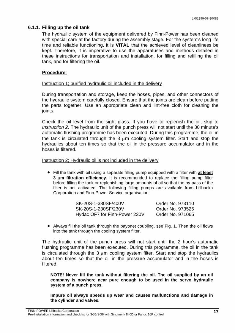
6.1.1. Filling up the oil tank The hydraulic system of the equipment delivered by Finn-Power has been cleaned with special care at the factory during the assembly stage. For the system's long life time and reliable functioning, it is VITAL that the achieved level of cleanliness be kept. Therefore, it is imperative to use the apparatuses and methods detailed in these instructions for transportation and installation, for filling and refilling the oil tank, and for filtering the oil. Procedure: Instruction 1; purified hydraulic oil included in the delivery During transportation and storage, keep the hoses, pipes, and other connectors of the hydraulic system carefully closed. Ensure that the joints are clean before putting the parts together. Use an appropriate clean and lint-free cloth for cleaning the joints. Check the oil level from the sight glass. If you have to replenish the oil, skip to Instruction 2. The hydraulic unit of the punch press will not start until the 30 minute's automatic flushing programme has been executed. During this programme, the oil in the tank is circulated through the 3 μm cooling system filter. Start and stop the hydraulics about ten times so that the oil in the pressure accumulator and in the hoses is filtered. Instruction 2; Hydraulic oil is not included in the delivery • Fill the tank with oil using a separate filling pump equipped with a filter with at least
3 μm filtration efficiency. It is recommended to replace the filling pump filter before filling the tank or replenishing large amounts of oil so that the by-pass of the filter is not activated. The following filling pumps are available from Lillbacka Corporation and Finn-Power Service organisation:
SK-20S-1-380SF/400V Order No. 973110 SK-20S-1-230SF/230V Order No. 973525 Hydac OF7 for Finn-Power 230V Order No. 971065
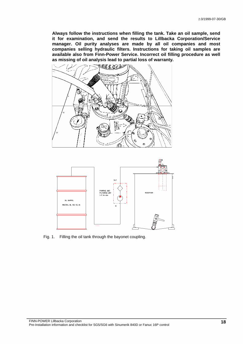
• Always fill the oil tank through the bayonet coupling, see Fig. 1. Then the oil flows
into the tank through the cooling system filter. The hydraulic unit of the punch press will not start until the 2 hour's automatic flushing programme has been executed. During this programme, the oil in the tank is circulated through the 3 μm cooling system filter. Start and stop the hydraulics about ten times so that the oil in the pressure accumulator and in the hoses is filtered.
NOTE! Never fill the tank without filtering the oil. The oil supplied by an oil company is nowhere near pure enough to be used in the servo hydraulic system of a punch press. Impure oil always speeds up wear and causes malfunctions and damage in the cylinder and valves.
2.0/1999-07-30/GB
FINN-POWER Lillbacka Corporation Pre-Installation information and checklist for SG5/SG6 with Sinumerik 840D or Fanuc 16P control 18
Always follow the instructions when filling the tank. Take an oil sample, send it for examination, and send the results to Lillbacka Corporation/Service manager. Oil purity analyses are made by all oil companies and most companies selling hydraulic filters. Instructions for taking oil samples are available also from Finn-Power Service. Incorrect oil filling procedure as well as missing of oil analysis lead to partial loss of warranty.
Fig. 1. Filling the oil tank through the bayonet coupling.
2.0/1999-07-30/GB
FINN-POWER Lillbacka Corporation Pre-Installation information and checklist for SG5/SG6 with Sinumerik 840D or Fanuc 16P control 19
7. Installation The Finn-Power turret punch press is installed and commissioned under the supervision of the manufacturer’s representative and according to his instructions. The machine must not be used before the commissioning and initial service have been carried out. The machine operators must have sufficient operator and safety before they are allowed to operate the system on their own.
.
7.1. Equipment and tools required The equipment mentioned below has to be available for the installation personnel during the entire installation process. Waiting for equipment causes excessive costs and delays in commencing the production.
Forklift truck with a minimum lifting capacity of 1800 kg and a min. lifting height of 2m
Rotary hammer drill, e.g. Hilti. Bit sizes 8, 10, 12, 14, 16 mm. Vacuum cleaner Manually-operated hydraulic jack of 10 t Approved hoisting belts or sling chains Hand grinder Lock-up cabinet for keeping the tools
7.2. Assisting personnel One or two assistants are needed for erecting the system. This is a unique occasion for the operating and service personnel to make themselves familiar with the machine.
7.3. Telephone connection If the delivery includes FINN-POWER Teleservice capability, the system control cabin must be equipped with a telephone connection. This is recommended also for systems without the teleservice option.

2.0/1999-07-30/GB
FINN-POWER Lillbacka Corporation Pre-Installation information and checklist for SG5/SG6 with Sinumerik 840D or Fanuc 16P control 20
8. Preparations for system start-up After the installation, production has to be run for 20-30hrs with the equipment to check the final adjustments. To be able to commence the production without delay, the Customer has to arrange the items mentioned below already during the first days of installation.
8.1. Test programs The Customer prepares test programs of his own production pieces for approx. 4 days run. If the Customer has not previous experience of programming a Finn-Power turret punch press, the Dealer's programming training engineer will assist in preparing the programs. The programming training engineer has to check all the programs before production run.
8.2. Punching tools The start-up engineer informs you at the beginning of installation when the punching tools can be mounted in the turret. The Customer has to assemble all the tools required for the test runs already before the installation or during the first days of installation. The Dealer's training engineer will assist and guide in assembling and mounting the tools if necessary.
8.3. Raw materials The Customer supplies raw material for at least 4 days production. Test blank sheets (e.g. 1.5 x 1250 x 2500) are needed already at the initial installation stage for testing purposes.
2.0/1999-07-30/GB
FINN-POWER Lillbacka Corporation Pre-Installation information and checklist for SG5/SG6 with Sinumerik 840D or Fanuc 16P control 21
ENC 1
2.0/1999-07-30/GB
FINN-POWER Lillbacka Corporation Pre-Installation information and checklist for SG5/SG6 with Sinumerik 840D or Fanuc 16P control 22
ENC 2
Please specify the optimal order in which the modules of the system should be brought to the installation site.
Turret punch press __________
Right angle shear (RS) __________
Stacking system (STS) __________
Automatic storage (CS) ________
2.0/1999-07-30/GB
FINN-POWER Lillbacka Corporation Pre-Installation information and checklist for SG5/SG6 with Sinumerik 840D or Fanuc 16P control 23
ENC 3
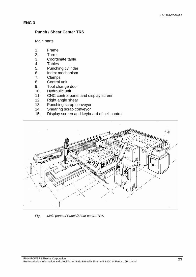
Punch / Shear Center TRS Main parts 1. Frame 2. Turret 3. Coordinate table 4. Tables 5. Punching cylinder 6. Index mechanism 7. Clamps 8. Control unit 9. Tool change door 10. Hydraulic unit 11. CNC control panel and display screen 12. Right angle shear 13. Punching scrap conveyor 14. Shearing scrap conveyor 15. Display screen and keyboard of cell control
Fig. Main parts of Punch/Shear centre TRS