PRE-FEASIBILITY REPORT Onenvironmentclearance.nic.in/writereaddata/FormB/TOR/PFR/...PRE-FEASIBILITY...
34
PRE-FEASIBILITY REPORT On Addition of Electronic Carousel Filling System At Plot no. 144 to 148, & 115 to 119, Baikampady Industrial area, Mangalore, Dakshina Kannada District Karnataka Project Proponents M/s. Bharat Petroleum Corporation limited Mangalore Environmental Consultants M/s. Aqua Tech Enviro Engineers, (Environmental Engineers & Consultants) # 3391, 6th Main, 3rd Cross, RPC Layout, Vijayanagar II Stage, Bangalore – 560 040 Tele Phone: 080: 23141679 Fax: 080:23148166 E-mail: [email protected]
Transcript of PRE-FEASIBILITY REPORT Onenvironmentclearance.nic.in/writereaddata/FormB/TOR/PFR/...PRE-FEASIBILITY...
Contents
Particulars
INTRODUCTION
PRE-FEASIBILITY REPORT
On
Addition of Electronic Carousel Filling System
At
Plot no. 144 to 148, & 115 to 119, Baikampady Industrial area, Mangalore, Dakshina Kannada District
Karnataka
Project Proponents
M/s. Bharat Petroleum Corporation limited Mangalore
Environmental Consultants
M/s. Aqua Tech Enviro Engineers,
(Environmental Engineers & Consultants)
# 3391, 6th Main, 3rd Cross, RPC Layout,
Vijayanagar II Stage, Bangalore – 560 040
Tele Phone: 080: 23141679
Fax: 080:23148166
E-mail: [email protected]

M/s. Bharat Petroleum Corporation Limited
Project Report
Contents
Sl.No Particulars Page No.
Chapter-1 Executive Summary
1.1 Introduction 1
1.1.1 Preamble 1
1.1.2 Location Of The Project 1
1.1.3 Project At A Glance: 1
1.1.4 Summary Of The Project 2
Chapter-2 Introduction To project proponent/ project
2.1 Introduction Of Project Proponent 3
2.2 Brief Description Of Nature Of The Project 3
2.3 Need For The Additional Carousal 3
2.4 Demand Supply Gap 4
2.5 Imports Vs. Indigenous Production 4
2.6 Export Possibility 4
2.7 Employment Generation 4
Chapter-3 Process Description
3.1 Type of project 5
3.2 Location of the project 5
3.3 Basis For Selecting The Proposed Site 6
3.4 Size Or Magnitude Of Operation 6
3.5 Process Description 7
3.5.1 Technical Specifications Of - 24 Station Carousel & Associated Upstream & Downstream Equipment
8
3.6 Water Requirement And Wastewater Treatment And Discharge Details
13
3.7 Air Pollution Details: 14
3.8 Noise Pollution Details 15
3.9 Solid Waste Details 15
3.10 Hazardous Waste Generation And Its Management During Operation Phase:
16
3.11 Rain Water Harvesting 16
3.12 Solar Lighting Facility 16
3.13 Schematic representation of the feasibility drawing which give information of EIA purpose
17
Chapter-4 Site Analysis
4.1 Connectivity 18
4.2 Land Form, Land Use & Ownership: 19
4.3 Topography 19
4.4 Existing Infrastructure: 20
4.5 Assessment Of Infrastructure Demand 20
4.6 Soil Classification 20

M/s. Bharat Petroleum Corporation Limited
Project Report
4.7 Climatic Data From Secondary Sources 21
Chapter-5 Planning Brief
5.1 Planning Concept 27
5.2 Population Projection 27
5.3 Land use planning 27
5.4 Assessment Of Infrastructure Demand 27
5.5 Amenities/Facilities 27
Chapter-6 Proposed Infrastructure
6.1 Industrial Area (Processing Area) 28
6.2 Green-Belt 28
6.3 Drinking Water Management 28
6.4 Connectivity 28
6.5 Sewerage System 28
6.6 Solid Waste Management 28
6.7 Power Requirement & Supply Source 28
Chapter-7 Rehabilitation & Resettlement Plan
29
Chapter-8 Project Schedule And Cost Estimates
8.1 Time Schedule: 29
8.2 Estimated Project Cost 29 Chapter-9
Analysis of Proposal 30
Tables Contents
3.1 Land-Use Pattern 6
3.2 Water Consumption And Sewage Discharge 13
3.3 Sewage/Wastewater Treatment And Discharge
14
3.4 Air Pollution Sources, Fuel Consumption And Chimney Height Details
15
3.5 Solid Waste Generation During The Operation Phase 16
3.6 Hazardous Waste Generation 16
4.1 Connectivity from the Project Site 18
4.2 Meteorological data of Mangalore for the year 2014 21
5.1 Land Use Pattern 27
8.1 Capital Investment On The Project 29
Figures
3.1 Goggle Map Showing The Project Site
5 3.2 Location Map Of The Project Site
6
3.3 Photograph Of Typical Carousal System
8 4.1 Google Map showing site Connectivity 18 4.2 Land Use Map 19
4.3 Wind rose diagrams 23

M/s. Bharat Petroleum Corporation Limited
Project Report
M/s. Bharat Petroleum Corporation Limited
Project Report
1
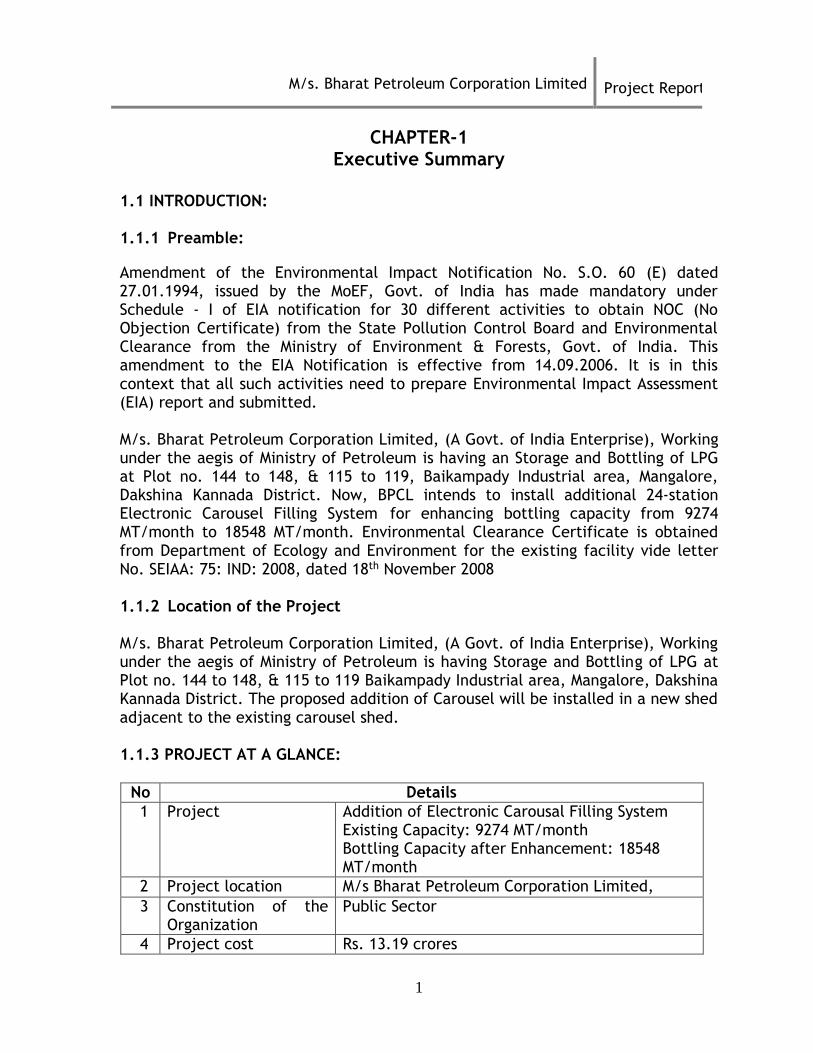
CHAPTER-1 Executive Summary
1.1 INTRODUCTION: 1.1.1 Preamble:
Amendment of the Environmental Impact Notification No. S.O. 60 (E) dated 27.01.1994, issued by the MoEF, Govt. of India has made mandatory under Schedule - I of EIA notification for 30 different activities to obtain NOC (No Objection Certificate) from the State Pollution Control Board and Environmental Clearance from the Ministry of Environment & Forests, Govt. of India. This amendment to the EIA Notification is effective from 14.09.2006. It is in this context that all such activities need to prepare Environmental Impact Assessment (EIA) report and submitted. M/s. Bharat Petroleum Corporation Limited, (A Govt. of India Enterprise), Working under the aegis of Ministry of Petroleum is having an Storage and Bottling of LPG at Plot no. 144 to 148, & 115 to 119, Baikampady Industrial area, Mangalore, Dakshina Kannada District. Now, BPCL intends to install additional 24-station Electronic Carousel Filling System for enhancing bottling capacity from 9274 MT/month to 18548 MT/month. Environmental Clearance Certificate is obtained from Department of Ecology and Environment for the existing facility vide letter No. SEIAA: 75: IND: 2008, dated 18th November 2008 1.1.2 Location of the Project M/s. Bharat Petroleum Corporation Limited, (A Govt. of India Enterprise), Working under the aegis of Ministry of Petroleum is having Storage and Bottling of LPG at Plot no. 144 to 148, & 115 to 119 Baikampady Industrial area, Mangalore, Dakshina Kannada District. The proposed addition of Carousel will be installed in a new shed adjacent to the existing carousel shed. 1.1.3 PROJECT AT A GLANCE:
No Details
1 Project Addition of Electronic Carousal Filling System Existing Capacity: 9274 MT/month Bottling Capacity after Enhancement: 18548 MT/month
2 Project location M/s Bharat Petroleum Corporation Limited, 3 Constitution of the
Organization Public Sector
4 Project cost Rs. 13.19 crores

M/s. Bharat Petroleum Corporation Limited
Project Report
2
1.1.4 Summary of the Project
Sl.No
Particulars Existing Additional
1 Bottling Capacity 9274 MT/month 9274 MT/Month
2 Land 40 acres No additional Land required
3 Storage capacity of LPG
1750 MT 1750 MT
4 Man power 150 35
5 Project cost 41.18 crores 13.19 crores
6 Water requirement Domestic: 5500 LPD Cylinder washing: 2000LPD Oil water separation unit provided for cylinder conveyor system: 1000 LPD
Domestic: 1300 LPD Cylinder washing: 2000LPD Oil water separation unit provided for cylinder conveyor system: 1000 LPD
7 Solid waste Domestic: 27 Kg/d Domestic: 7 Kg/d
8 Power 1x500 KVA, 1x250 KVA, 1x200 KVA, 1x125 KVA,1X62.5 kVA,1X7.5kVA
1x600 KVA. (1x250 KVA, 1x200KVA shall be dismantled) after putting up new DG
5 Total Man power requirement during operation
Existing: 150 Proposed: 35

M/s. Bharat Petroleum Corporation Limited
Project Report
3
CHAPTER-2 Introduction of the Project/Background Information
2.1 INTRODUCTION OF PROJECT PROPONENT
Bharat Petroleum Corporation Limited (BPCL) is an Indian state-controlled oil and
gas company headquartered in Mumbai, Maharashtra. BPCL has been ranked 280th
in the Fortune Global 500 rankings of the world's biggest corporations for the year
2015.
BPCL, is a leading player in the Petroleum Sector in the country. BPCL currently
has Refineries at Mumbai and Kochi, BPC's subsidiary at Numaligarh for refining
crude oil.
Also, Bharat Oman Refineries Ltd. (BORL) a joint venture of BPCL, a state-of-art,
grass root refinery at Bina, Dist. Sagar, Madhya Pradesh is also a part of BPCL. This
Refinery is on stream and completely operational from 2011.
2.2 BRIEF DESCRIPTION OF NATURE OF THE PROJECT
M/s Bharat Petroleum Corporation Limited intend to install Additional 24-station
Electronic Carousel Filling System for bottling additional 9274 MT/month (i.e.
22,000 Cylinders per day). Whereas, the Bulk LPG storage and cylinder storage
capacity of the installation remains the same.
2.3 NEED FOR THE ADDITIONAL CAROUSEL
The existing 24 station Carousal can bottle 9274 MT/month (i.e 22,000 cylinders
per day) which is meeting the demand of 9 districts of Karnataka Udupi, Dakshina
Kannada, Shimoga, Davangere, Mysore, Chamarajanagar, Kodagu, Hassan,
Chikmagalur and 2 districts of Kerala Kannur & Kasaragod. Due to the increased
demand of LPG and having adequate LPG storage capacity M/s. BPCL intend to
install Additional 24-station Electronic Carousel Filling System for bottling
additional 9274 MT/month (i.e 22,000 Cylinders per day). Whereas, the Bulk LPG
storage and cylinder storage capacity of the installation remains the same. The
LPG is stored in Bullets of capacity 125MT (4nos), Spheres of capacity 650MT (1
no.) and Mounded Storage Vessel of capacity 600MT (1 no.)

M/s. Bharat Petroleum Corporation Limited
Project Report
4
2.4 DEMAND SUPPLY GAP
The LPG demand is increasing so to meet the demand of the local market M/s.
Bharat Petroleum Corporation Limited intend to install Additional 24-station
Electronic Carousel Filling System for bottling additional 9274 MT/month (i.e.
22,000 Cylinders per day).
2.5 IMPORTS VS. INDIGENOUS PRODUCTION
LPG will be imported from Kochi Port to Mangalore for bottling.
2.6 EXPORT POSSIBILITY
The export possibility is not being contemplated and the filled LPG cylinders will
be marketed to cater to meet the needs of local market.
2.7 EMPLOYMENT GENERATION Existing man power in the unit are 150, in the proposed expansion about 35 people
will be employed.

M/s. Bharat Petroleum Corporation Limited
Project Report
5
Chapter-3
PROJECT DESCRIPTION
3.1 TYPE OF PROJECT
M/s. Bharat Petroleum Corporation Limited, (A Govt. of India Enterprise), Working under the aegis of Ministry of Petroleum is having a Storage and Bottling of LPG at Plot no. 144 to 148, & 115 to 119, Baikampady Industrial area, Mangalore, Dakshina Kannada District. Now, BPCL intends to install additional 24-station Electronic Carousel Filling System for enhancing bottling capacity from 9274 MT/month to 18548 MT/month. 3.2 LOCATION OF THE PROJECT
Figure 3.1 Goggle Map Showing the Project Site Latitude: 12056’55.19 N Longitude: 74049’26.28”E MSL: 32m

M/s. Bharat Petroleum Corporation Limited
Project Report
6
Figure 3.2 Location Map of the project site
3.3 BASIS FOR SELECTING THE PROPOSED SITE
The site is located at Plot no. 144 to 148, & 115 to 119, Baikampady Industrial
area, Mangalore, Dakshina Kannada District. The site is well connected with
roadways and it is located near to the port Mangalore with which the material
transportation is easy. The proposed expansion will be installed adjacent to the
old carousal. No alternative sites have been considered as the expansion of
carrousel is being planned in the existing plant.
3.4 SIZE OR MAGNITUDE OF OPERATION
The BPCL Plant is located in a total area of 40 Acres and is sufficient for the
proposed addition and it also maintains adequate green belt area. The land use
pattern of the industry is as follows.
Table: - 3.1 Land-use pattern
Sl. No.
Particulars Area in Acres Percentage (%)
1 Total plot area 40 100
2 Ground coverage area / Storage area
2 5
3 Hard paved area 8.5 21.25
4 Landscape area 29.5 73.75
Project site

M/s. Bharat Petroleum Corporation Limited
Project Report
7
3.5 PROCESS DESCRIPTION:
Flow diagram of Plant:
Flow Diagram For Receipt Of Product:
Flow Diagram for Receipt Filling & Dispatch of Cylinder:
Checking of empty cylinder lorry at main gate & frisking of driver for any inflammable
material
Counting of cylinder at empty shed and segregation of cylinder (DPT,HR, Dent, Bulge,
Corroded, cut)
Filling of the cylinder in carousel and post quality check (Weight check, valve leak check, Bung leak check, O ring leak check, body leak check) and sealing of
the cylinder
Dispatching of the cylinder as per ‘Plan Delivery
Program’
RECEIVES LPG THROUGH PIPELINE / TANK TRUCKS
STORAGE OF LPG IN PRESSURE VESSEL (4 X 125 MT, 1 X650MT &1X600
MT)
FILLING LPG IN CYLINDER (5 KG, 14.2 KG, 19 KG, 35 KG.47.5 KG, LOT 35 KG & 19 KG BMCG)
DISPATCH OF CYLINDER TO
DISTRIBUTOR
Checking ullage
in storage vessel
Indenting for the product required based on the ullage
available
Lining up of the vessel to which product will be
taken
Coordinating with MLIF and receiving of the product in storage vessel

M/s. Bharat Petroleum Corporation Limited
Project Report
8
Figure 2.1 Photograph of Typical Carousal System
3.5.1 TECHNICAL SPECIFICATIONS OF - 24 STATION CAROUSEL & ASSOCIATED
UPSTREAM & DOWNSTREAM EQUIPMENT
SL
NO
ITEM BPCL’S SPECIFICATIONS
I. Operating Conditions : 24 Station Electronic machine carousel suitable
for filling 14.2/19 KG SC Type Valve cylinders simultaneously
1 System performance parameters
i) Production Capacity
ii) Filling Accuracy
iii) Valve Leak Detection
iv) O-Ring Leak
Detection
1570 Cylinders per hour for filling of 14.2 Kgs capacity at a carousel speed of 55 seconds per revolution and 1000 Cylinders per hour for filling of 19 Kgs capacity filling 95% of cylinders within +/- 50 gms or better 0.5 gm / hr
0.5 gm / hr

M/s. Bharat Petroleum Corporation Limited
Project Report
9
2 Cylinder
Dimensions
As per Cylinder Data Sheet provided at the end of this data sheet
3 Installation Under covered roof all sides open 4 Duty Continuous
5 No. of hrs/day 16 hrs /day for 300 days in a year
II Carousel Filling Machines :
1 Type Electronic type with individual Gas stops valve
and filling head.
2 Platform Level + 550 mm from floor level.
3. LPG Cylinder 14.2 Kg and 19 Kg
4 Working Pressure of LPG
Max. 8.5 Kg/cm2 (Differential pressure)
5. Filling Time
(Max.) at
working pressure
of 16 Kg/cm2
Vendor to Specify considering rotation time 55 Seconds
6. Valve Details Refer to enclosed drawing
7 Type of Filling
Gun required
Automatic lowering and centering type for SC Valve
with pin travel of 2.8 +/- 0.2mm.
8 Accuracy of filling
(Min.)
+/- 50 gms. Or better
9 Filter 40 Mesh SS Strainer.
10 Bourden type 0-25 Kg Pressure Gauge
To be provided before & after the filter
11 Guide Rail I – Section/Square Section.
12 Carousel drive (Anti
Static)
Preferable – Tyre/Belt driven with hydraulic motor or
Gear type with electric motor driven. Vendor to
specify.
13 Introduction unit Pneumatic / hydraulic operated or Gear type with
electric motor driven unit with automatic
introduction of cylinders synchronous with the speed of
the carousal. A safety device to be provided to prevent
introduction of cylinders to the carousal if there is
already a cylinder present on the filling machines i.e.
Introduction only when machines platform empty.

M/s. Bharat Petroleum Corporation Limited
Project Report
10
14 Ejection unit Pneumatic / hydraulic operated unit or Gear
type with electric motor driven for automatic ejection
of cylinders from the carousal to the chain conveyor.
A safety device to be provided such that if the filling
head has not detached from the cylinder then
carousel should stop gradually . By this Anti
jamming output is ensured i.e.
Ejection only when cylinders are filled and
gun released. Also the ejection has to operate only
when the conveyor is free.
15 Emergency stop Easily accessible from front & distinctly visible.
16 Earthing connection
a) Filling gun - braided copper wire along
with hose with insert
b) Central column.
c) Guide Rail
d) Platform
e) Frame 17 Safety Guard Mesh or M.S. Flat on angle iron frames all
around 1" above the platform.
18 Filling accuracy +/- 50 gm. Or better.
19 Utilities required
& consumption
per hour of
operation.
Compressed Air
requirement in
LPM
& Air pressure in
Kg/cm2
(To be specified by vendor) Air pressure supplied
is 5-6 Kg/cm2
20 Paint High quality anti-corrosive
21 Working height Tare weight controls to be accessible from floor
level. III Details of Central Column & Rotary Table Design
1 Product feed
distribution & by-pass
LPG thru Top and air through bottom of
column preferred
2 Sealing arrangement
details
To be provided for positive segregation of
LPG and Air
3 Table supporting
arrangement
Should be supported on rails

M/s. Bharat Petroleum Corporation Limited
Project Report
11
4 Table construction
arrangement.
Steel frame
5 Leveling arrangement Preferably by tripod
6 Material of
construction.
Steel
IV Drive Arrangement :
1 Drive motor type
rating &
characteristics
Hydraulic or electric with tyre/gear drive
Rating & characteristics to be specified by
vendor
2 Speed reducing gearbox
make type size &
complete details.
Through Frequency control
3 Final anti-static drive
arrangement details.
Arrangement to be indicated
V Filling Head :
1 Release Smooth release with hinged arrangement in jaws
to facilitate little downward movement of jaws
at the time of release
2 Liquid pressure 8.5 Kg/Cm2 (Differential) 3 Pin travel 2.8 + /- 0.2 mm 4 Flow rate 150 LPM
5 Material Gun metal 6 Head cap Gun metal threaded
SL
NO
ITEM BPCL'S REQUIREMENT
VI General :
1 Wheel details Steel wheel with sealed bearings.
2 LPG and Air hoses Should be anti-static 3 All safety features Should be built in by design.
4 Gas cut off system Should be automatic with pneumatic actuator
mounted on ball valves. VII Other Requirements 1 Air Quality (Moisture
Content) 5 Degree Below the Minimum Ambient Temperature. For all other parameters such as dust etc, vendor to provide suitable Air Filter Regulators

M/s. Bharat Petroleum Corporation Limited
Project Report
12
DATA SHEETS
FOR FLP ENCLOSURES
SR.
NO.
SPECIFICATIONS
1 Type of enclosure
for electronics
FLP conforming to IEC - 60079 or
Equivalent
a) Size As required
b) Cover Threaded Gaskets having an opening of
suitable dia. with toughened flat glass
sealed in the cover on the both sides.
c) Isolation switch 2Nos. switches for power ON/OFF
d) Interconnection to top
and bottom enclosure
Through FLP nipples
e) Mounting plate Suitable mounting plate shall be provided
for electronics f) Cable entry Back / bottom entry for 3/4" NT
2 Area of use Hazardous zone-1 Group IIA/IIB
3 Material LM6 4 Protection Class IP 65 5 Glands Flame proof double compression made of
brass and chrome plated type
6 Mounting To be mounted on cold bent pipe structure
at about 1.5 M from floor level.
SPECIFICATION FOR FLP GLANDS
Sl.NO
.
SPECIFICATIONS
1. Type FLP Double Compression conforming to IEC 60079.
2. Type of Armour Round GI wire
3. Area of use Hazardous Zone-GI Group IIA/IIB 4. Material
a) Gland Brass with Chrome Plating / Aluminium
5. Protection Class IP 66 6. Size As per requirement.
DATA SHEETS
FOR INTRINSICALLY SAFE ZENNER BARRIERS
Sl.
NO.
SPECIFICATIONS
1 Type Double channel. MTL/STAHL make
(Replaceable fuse types preferred)

M/s. Bharat Petroleum Corporation Limited
Project Report
13
2 Application & model for
limit switches
For interfacing limit & keyboard
switches/key boards & load cells
installed in hazardous area should be in
FLP enclosures. Both the channels
should be separate from the earth
circuit of the zener barrier. 3 Area of installation of
limit switches
Zone-I Class IIA/IIB
4 Area of installation of
zener barriers
At safe area in FLP enclosures
5 Supply Voltage 10 to 35 V DC positive with respect
to earth 6 Output current Up to 35 mA
7 Polarity Positively polarized
8 Terminals Should accommodate 1.5 sq. mm
Conductors. 9 Operating Temperature -20 to + 55 degree Celsius
10 Humidity limit 95% RH 11 Conformity standard IS 10398 of 1982 or equivalent 12 Conformity Certification PESO Nagpur India
13 Mounting Suitable to mount on the bus bar
inside FLP enclosure. 3.6 WATER REQUIREMENT AND WASTEWATER TREATMENT AND DISCHARGE DETAILS i) QUANTITY OF WATER REQUIRED AND WASTEWATER GENERATED: The total quantity of water requirement for the industry is about 8.5 KLD. The break-up of the consumption of water is as presented in table below.
Table 3.2 Water Consumption and Sewage Discharge
Description Consumption
(m3/day)
Discharge
(m3/day)
(a) Domestic (toilet,
canteen etc.)
5.5 4.4
(b) Cylinder washing 2 2
(c) Oil water
separation unit
provided for cylinder
conveyor system
1 1

M/s. Bharat Petroleum Corporation Limited
Project Report
14
ii) WASTEWATER TREAMENT AND DISPOSAL DETAILS:
The treatment methods and the final disposal of each type of wastewater generated is appended in the table below
Table3.3 Sewage/Wastewater Treatment and Discharge
Sewage/effluent generated from
Treatment units provided Final disposal point
(a) Domestic Septic tank Soak pit
(b) Cylinder washing
Sedimentation treatment Overflow of sedimentation tank will be led to green belt development
(c) Oil water separation unit provided for cylinder conveyor system
Cylinder conveying system will be frequently lubricated for smooth movement of cylinders through soap water, spillages will be taken to ETP consisting of Oil water separation unit
Recycled
3.7 AIR POLLUTION DETAILS: The major air pollution sources from the industry are DG set. These sources are
provided with stacks of adequate height so as to disperse the emanating flue gases
containing SPM, oxides of sulfur and nitrogen without affecting the ground level
concentrations.
The sources of air pollution, type of fuel used, fuel consumption and chimney
heights for air pollution sources of the proposed project are indicated in the
following Table-3.4.

M/s. Bharat Petroleum Corporation Limited
Project Report
15
Table3.4 Air pollution sources, fuel consumption and chimney height details
SI. no.
Stack attached to
Fuel used
Sulfur content
Fuel consumption L/h
Stack/s height
Air pollution control unit
Predicted emissions
1 D.G. set:
Existing:,
1x500 KVA,
1x250 KVA,
1x200 KVA
1x125 KVA
1X62.5 KVA
1X7.5 KVA
Proposed
1x600 KVA.
(1x250 KVA,
1x200KVA
will be
dismantled)
after putting
up new DG
HSD <0.025%
100 30 30 20 10 1 120
7m 5m 5m 5m 5m
1.5m
7m
Stack
SOx, NOx, SPM
3.8 NOISE POLLUTION DETAILS The major source of noise pollution in the industry is the DG set. The DG are with
integral acoustic measures. Also ambient noise levels will be ensured within the
ambient standards by inbuilt design of mechanical equipment and building apart
from vegetation (tree plantations) along the periphery and at various locations
within the industry premises.
3.9 SOLID WASTE DETAILS The quantity of solid waste generated from the proposed industry is detailed in the following table.

M/s. Bharat Petroleum Corporation Limited
Project Report
16
Table3.5 Solid Waste Generation during the Operation Phase
Total no. of employees 185
Assuming per capita solid waste generation rate as 0.20 kg/capita/day
Quantity of solid waste generated 37 kg/day
Organic solid waste : 60 % of the total waste 22.2 kg/day
Inorganic solid waste : 40 % of the total waste 14.8 kg/day
3.10 Hazardous waste Generation and Its Management during Operation Phase: The hazardous wastes generated is spent oil from DG set which is stored in MS
drums and sent to authorized preprocessors. The type and quantities of Hazardous
waste generated from various processes are shown in the following Table
Table 3.6 Hazardous Waste Generation
Hazardous waste Quantity of hazardous
waste generated
1. Used oil from DG Set 1000 L/A
3.11 Rain Water Harvesting Rain water harvesting has been implemented in the project the runoff water from
the open area is diverted to the ground water recharge pits for ground water
recharge. About 4 numbers of recharge pits have been constructed in the
installations.
3.12 Solar Lighting Facility
Solar street lights have been provided in the installations.

M/s. Bharat Petroleum Corporation Limited
Project Report
17
3.13 Schematic representation of the feasibility drawing which give information of EIA purpose

M/s. Bharat Petroleum Corporation Limited
Project Report
18
Chapter-4 SITE ANALYSIS
4.1 CONNECTIVITY The well laid road network is available till the project site. National highway
17(Edapally Panvel highway) is about 1.1 km from project site, railway
connectivity from most of the parts which is about 10 km. The major connectivity
to the project is provided with distance and site bearing in table 4.1 as under.
Table 4.1: Connectivity from the Project Site
Sl. No.
Road Distance from the project site (km) aerial distance
Direction w.r.t. project
site
1 Edapally Panvel highway 1.1 West
2 Mangalore Port 1.8 South west
3 Mangalore airport 5.15 East
4 Thokur railway station 1.75 North East
5 Gurupura River 1.5 South
6 Mangalore City 3 South
7 Mangalore railway station 10 South
Fig 4.1: Google Map Showing Connectivity
Project Site

M/s. Bharat Petroleum Corporation Limited
Project Report
19
4.2 LAND FORM, LAND USE & OWNERSHIP: M/s. Bharat Petroleum Corporation Limited, (A Govt. of India Enterprise), Working under the aegis of Ministry of Petroleum is having Storage and Bottling of LPG at Plot no. 144 to 148, & 115 to 119, Baikampady Industrial area, Mangalore, Dakshina Kannada District. The proposed addition of Carousal will be installed adjacent to the existing carousal.
Land-use pattern
Sl. No.
Particulars Area in Acres Percentage (%)
1 Total plot area 40 100
2 Ground coverage area / Storage area
2 5
3 Hard paved area 8.5 21.25
4 Landscape area 29.5 73.75
Fig 4.2 Land Use Map
4.3 TOPOGRAPHY
M/s. Bharat Petroleum Corporation Limited is located at Latitude: 12056’55.19 N
Longitude: 74049’26.28”E at an elevation of 32 m above MSL.

M/s. Bharat Petroleum Corporation Limited
Project Report
20
4.4 EXISTING INFRASTRUCTURE: The list of existing infrastructure at the project site is 1. Water supply from Bore well 2. Power supply from MESCOM 3. Storm water drainage system is existing 4. Domestic sewage & domestic garbage treatment is provided.
4.5 ASSESSMENT OF INFRASTRUCTURE DEMAND M/s. Bharat Petroleum Corporation Limited has proposed to enhance the bottling capacity from 9274 MT/month to 18548 MT/month. The infrastructure demand for the project is detailed in the following sections 4.5.1 Roadways Roadways are required for
Roads are already available for the transportation of the cylinders 4.5.2 Water Supply & Sewerage Infrastructure: Water demand for the industry will be met by Bore well. The domestic sewage
generated is treated in septic tank & discharged into soak pit within the industry
premises.
4.6 SOIL CLASSIFICATION The soil in the district is mostly lateritic type, found distributed in the Pedi plain
area characterised by high iron and aluminium content. Lateritic soil is mostly red
in color and yellow loamy, pale to bright red colours are also seen. Lateritic soil is
suitable for Paddy, Sugarcane, Arecanut and Plantation crops, viz. crops like
Cardamom & plantains. Loamy red soils are distributed in the lower reaches of
valleys. Red lateritic soil is the most dominant soil type in the area. The texture of
the soil varies from fine to coarse. The soil in valleys and intermediate slopes is
rich in loam whereas in upper slopes it is much coarse in nature. The soil responds
well to irrigation and other soil - management practices. Silty and loamy soils are
of transported origin and are found mostly along river banks and in valley plains.
They have good infiltration capacity and are well-suited for agriculture due to
their fertility.

M/s. Bharat Petroleum Corporation Limited
Project Report
21
4.7 CLIMATIC DATA FROM SECONDARY SOURCES
Table 4.2: Meteorological data of Mangalore for the year 2014
Month Temperature 0C
Relative
humidity
%
Precipitation
rate
(mm/hr)
Atmospheric
pressure
(mb)
Wind
Speed
(m/s)
Inversion /
mixing
height
(m)
Cloud
cover
(tenths)
Min Max Min Max Min Max Min Max Average Day Night Min Max
Jan 20.5 28.3 61 71 0 0 1002 1012 7.7 1769 2554 2 10
Feb 21.3 28.9 66 75 0 2.29 1001 1011 6.2 1800 2021 2 10
Mar 22.7 30.4 67 75 0 2.54 1001 1011 7.7 1848 2563 2 10
Apr 24.1 32.4
69 73 0 1.78 1000 1010 6.2 2024 1459 2 10
May 25.1 32.5 72 77 0 4.32 1001 1008 7.7 1705 1459 2 7
June 24.7 29.3 85 89 0 7.62 1000 1008 9.8 1893 1449 2 10
July 23.8 28.7 88 91 0 4.57 999 1009 7.7 1822 950 3 10
Aug 24.1 28.1 87 91 0 4.83 999 1008 7.7 1766 1028 3 10
Sept 22.1 28.1 83 89 0 27.43 999 1010 7.7 1780 1439 2 10
Oct 21.0 31.1 79 85 0 1.52 1002 1010 6.2 1949 2156 2 10
Nov 22.8 31.5 69 77 0 0.51 1000 1010 8.7 1949 3139 2 10
Dec 20.4 30.3 62 69 0 0.51 1003 1011 7.7 1850 2697 2 10
1. TEMPERATURE
The mean maximum temperature is observed at (32.5°C) in the month of May and
the mean minimum temperature at (20.4°C) is observed in the month of
December.
In the summer season the mean minimum temperature is observed during the
month of March (22.7°C). During the monsoon the mean maximum temperature is
observed to be 32.5°C in the month of May with the mean minimum temperature
at 22.1°C during September. By the end of September with the onset of post
monsoon season (October - November), day temperatures drop slightly with the
mean maximum temperature at 31.5°C in November and mean minimum
temperature is observed at 21°C & 22.80 for both October & November. The values
are presented in table 4.2.
2 RELATIVE HUMIDITY
Minimum and maximum values of relative humidity have been recorded. The
minimum humidity is observed to be at 61 % in the month of January and the
maximum is 91 % in the month of July to August. The mean minimum values of
humidity during summer, monsoon, post-monsoon and winter seasons are 67%,
22.1%, 69 % & 61% during the months of March, September, November and January
respectively. Similarly the maximum values are 77%, 91%, 85%, 66% in the months

M/s. Bharat Petroleum Corporation Limited
Project Report
22
of May, July, October & February during the summer, monsoon and post monsoon
& winter seasons. The values are presented in table 4.2.
3 RAINFALL
The monsoon in this region usually occurs twice in a year i.e. from June to
September and from October to November. The maximum annual rate of
precipitation over this region ranges between 0.51 to 27.43 mm/hr. the Annual
rain fall in Mangalore is 3479 mm.
4 ATMOSPHERIC PRESSURE
The maximum and the minimum atmospheric pressures are recorded during all
seasons. In the summer season, the mean maximum and minimum pressure values
are observed to be 1011 mb in the month of March and 1000 mb in the month of
April respectively. During monsoon season, the maximum pressure is 1009 mb and
minimum 999 mbin July and August. The maximum pressure during the post-
monsoon season is observed to be 1011 mb in December and minimum pressure is
1000 mb in the month of November. During the winter season the minimum
atmospheric pressure is 1000 mb in November and the maximum is 1012 mb in the
month of January. The values are presented in table 4.2
5 INVERSION HEIGHT
The maximum inversion heights at the project site during the day time & night
time for all the months of the year is as given in the table 3.1. The maximum
mixing height of 3139 m is observed during the month of November during the
night time and 2024 m during the month of April during the day time. The
minimum inversion heights are 1705 m in the month of May during the day and 950
m during the night in the month of July.
6 CLOUD COVER
The minimum cover measured in the unit of tenths is 2 and the maximum observed
cloud cover is 10.
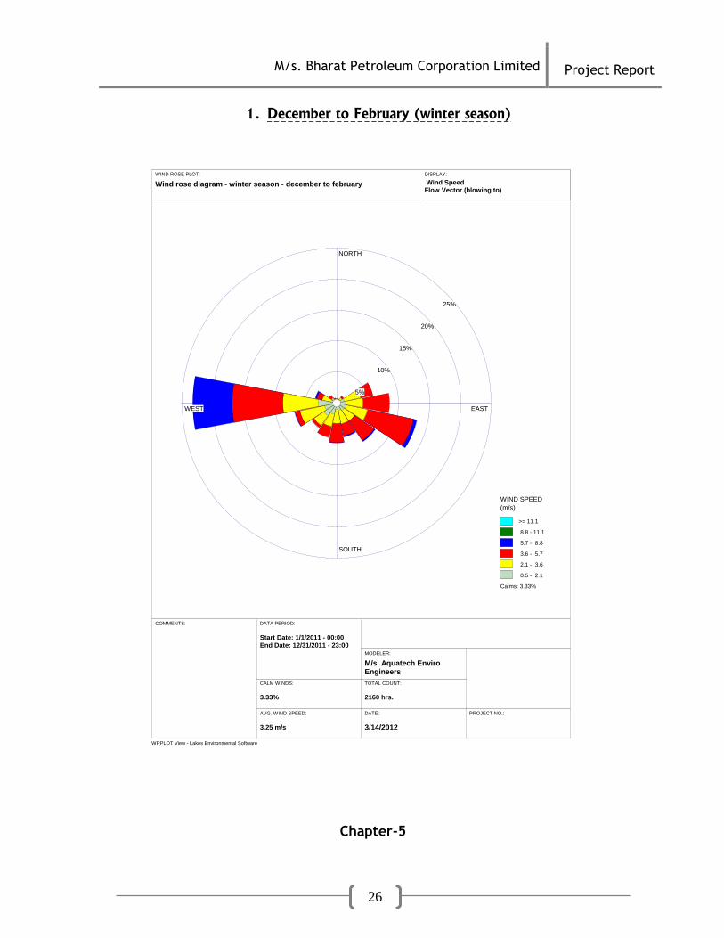
7 WIND
The data on wind patterns are pictorially represented by means of wind rose
diagrams for the entire year as figure 4.3 (for different seasons).

M/s. Bharat Petroleum Corporation Limited
Project Report
23
Fig 4.3: Wind rose diagrams
1. March to May (summer season)
WRPLOT View - Lakes Environmental Software
WIND ROSE PLOT:
Wind rose diagram - summer season - march to may
COMMENTS:
MODELER:
M/s. Aquatech Enviro Engineers
DATE:
3/14/2012
PROJECT NO.:
NORTH
SOUTH
WEST EAST
3%
6%
9%
12%
15%
WIND SPEED
(m/s)
>= 11.1
8.8 - 11.1
5.7 - 8.8
3.6 - 5.7
2.1 - 3.6
0.5 - 2.1
Calms: 4.71%
TOTAL COUNT:
2208 hrs.
CALM WINDS:
4.71%
DATA PERIOD:
Start Date: 3/1/2011 - 00:00End Date: 5/31/2011 - 23:00
AVG. WIND SPEED:
3.07 m/s
DISPLAY:
Wind SpeedFlow Vector (blowing to)

M/s. Bharat Petroleum Corporation Limited
Project Report
24
1. June to September (monsoon season)
WRPLOT View - Lakes Environmental Software
WIND ROSE PLOT:
Wind rose diagram - monsoon season - june to september
COMMENTS:
MODELER:
M/s. Aquatech Enviro Engineers
DATE:
3/14/2012
PROJECT NO.:
NORTH
SOUTH
WEST EAST
4%
8%
12%
16%
20%
WIND SPEED
(m/s)
>= 11.1
8.8 - 11.1
5.7 - 8.8
3.6 - 5.7
2.1 - 3.6
0.5 - 2.1
Calms: 2.87%
TOTAL COUNT:
2928 hrs.
CALM WINDS:
2.87%
DATA PERIOD:
Start Date: 6/1/2011 - 00:00End Date: 9/30/2011 - 23:00
AVG. WIND SPEED:
3.32 m/s
DISPLAY:
Wind SpeedFlow Vector (blowing to)

M/s. Bharat Petroleum Corporation Limited
Project Report
25
1. October to November (post monsoon season)
WRPLOT View - Lakes Environmental Software
WIND ROSE PLOT:
Wind rose diagram - post monsoon season - october to november
COMMENTS:
MODELER:
M/s. Aquatech Enviro Engineers
DATE:
3/14/2012
PROJECT NO.:
NORTH
SOUTH
WEST EAST
5%
10%
15%
20%
25%
WIND SPEED
(m/s)
>= 11.1
8.8 - 11.1
5.7 - 8.8
3.6 - 5.7
2.1 - 3.6
0.5 - 2.1
Calms: 5.12%
TOTAL COUNT:
1464 hrs.
CALM WINDS:
5.12%
DATA PERIOD:
Start Date: 10/1/2011 - 00:00End Date: 11/30/2011 - 23:00
AVG. WIND SPEED:
3.29 m/s
DISPLAY:
Wind SpeedFlow Vector (blowing to)
M/s. Bharat Petroleum Corporation Limited
Project Report
26
1. December to February (winter season)
WRPLOT View - Lakes Environmental Software
WIND ROSE PLOT:
Wind rose diagram - winter season - december to february
COMMENTS:
MODELER:
M/s. Aquatech Enviro Engineers
DATE:
3/14/2012
PROJECT NO.:
NORTH
SOUTH
WEST EAST
5%
10%
15%
20%
25%
WIND SPEED
(m/s)
>= 11.1
8.8 - 11.1
5.7 - 8.8
3.6 - 5.7
2.1 - 3.6
0.5 - 2.1
Calms: 3.33%
TOTAL COUNT:
2160 hrs.
CALM WINDS:
3.33%
DATA PERIOD:
Start Date: 1/1/2011 - 00:00End Date: 12/31/2011 - 23:00
AVG. WIND SPEED:
3.25 m/s
DISPLAY:
Wind SpeedFlow Vector (blowing to)
Chapter-5

M/s. Bharat Petroleum Corporation Limited
Project Report
27
PLANNING BRIEF
5.1 Planning Concept
M/s. Bharat Petroleum Corporation Limited, (A Govt. of India Enterprise), Working under the aegis of Ministry of Petroleum is having Storage and Bottling of LPG at Plot no. 144 to 148, & 115 to 119 Baikampady Industrial area, Mangalore, Dakshina Kannada District. The proposed addition of Carousel will be installed in a new shed adjacent to the existing carousel shed. 5.2 Population Projection
The population projection of Dakshina Kannada District as per 2011 census is
2,089,649.
5.3 Land use planning
5.1 Land-use pattern
Sl. No.
Particulars Area in Acres
Percentage (%)
1 Total plot area 40 100
2 Ground coverage area / Storage area
2 5
3 Hard paved area 8.5 21.25
4 Landscape area 29.5 73.75
5.4 ASSESSMENT OF INFRASTRUCTURE DEMAND
Interior roads are already available for dispatch of material for local
consumers.
Locally available man power will be utilized
The transport vehicle will be hired based on requirement.
5.5 AMENITIES/FACILITIES
Proper site services such as with Drinking water, safety equipments & first Aid will
be provided to the workers.
Chapter-6

M/s. Bharat Petroleum Corporation Limited
Project Report
28
PROPOSED INFRASTRUCTURE
6.1 INDUSTRIAL AREA (PROCESSING AREA) M/s. Bharat Petroleum Corporation Limited has proposed to enhance the bottling
capacity from 9274 MT/month to 18548 MT/month.
6.2 GREEN-BELT An area of 29.5 acres (i.e. 73.75 % of the total plot area) is reserved exclusively
for green-belt/landscape development where plantations of indigenous species are
grown
6.3 DRINKING WATER MANAGEMENT The source of water supply for the industry is Bore well. The total water requirement is about 5.5 KLD. 6.4 CONNECTIVITY The project site is well connected with roadways. National highway 17(Edapally
Panvel highway) is about 1.1 km from project site, railway connectivity from most
of the parts which is about 10 km.
6.5 SEWERAGE SYSTEM
The domestic sewage generated from the project is treated in septic tank &
discharged into soak pit. No Industrial effluent is generated in the project other
than cylinder washings which is treated in sedimentation tanks
6.6 SOLID WASTE MANAGEMENT The domestic garbage, solid waste generated goes to soak pit.
6.7 POWER REQUIREMENT & SUPPLY SOURCE The total power requirement for the installation is about 500KVA which is obtained
from MESCOM.
Further diesel generators are installed to serve as alternative sources of power
supply to this unit in emergencies during power failure.
Chapter-7

M/s. Bharat Petroleum Corporation Limited
Project Report
29
REHABILITATION & RESETTLEMENT PLAN
M/s. Bharat Petroleum Corporation Limited has proposed to enhance the bottling
capacity from 9274 MT/month to 18548 MT/month (i.e from 22,000 cylinders per
day to 44,000 cylinders per day). Addition of Carousel will be done in new shed
adjacent to the existing carousel shed. So Rehabilitation & Resettlement Plan is
not envisaged
Chapter-8
PROJECT SCHEDULE & COST ESTIMATES
8.1 TIME SCHEDULE: The plant is existing and is under operation, the proposed Addition expected to be completed by Aug, 2016. 8.2 ESTIMATED PROJECT COST:
Total capital investment on the Project is detailed as under
Table 8.1 Capital Investment on the Project
Sl. no.
Cost of In Rupees
1 Construction 100 Lakhs
2 Plant and machinery 1210 Lakhs
Total 1319 Lakhs
Rupees Thirteen Crore nineteen lakhs only
Chapter-9

M/s. Bharat Petroleum Corporation Limited
Project Report
30
ANALYSIS OF PROPOSAL
M/s. Bharat Petroleum Corporation Limited has proposed to enhance the bottling
capacity from 9274 MT/month to 18548 MT/month (i.e from 22,000 cylinders per
day to 44,000 cylinders per day). Following are the benefits of the project.
1. Substantial Socio-economic benefits.
2. Good Techno-commercial viability.
3. Around the project site semi-skilled and unskilled workmen are expected to
be available from local population in these areas to meet the manpower
requirement during construction and Operational phase.
4. There will be employment opportunity for local people during construction
and operation phase.
5. Critical analyses of the existing socio-economic profile of the area indicate
that the impacts of the Project is expected to be of varying nature. The
following are the impacts predicted.
6. Secondary employment will be generated thereby benefiting locals.
7. Thus a significant benefit to the socio-economic environment is likely to be
created due to the project.
8. Improve in Import and Export Business.