Pre Feasibility Report for In
79
Pre Feasibility Report for Capacity Expansion In Grain & Molasses Based Distillery From 120 KLD to 200 KLD (Cogeneration Power Plant from 04 MW) Through up-gradation & Addition of New Grain & Molasses Based unit of 300 KLD (Cogeneration Power Plant of 06 MW) At M/s Som Distilleries Pvt Limited Village –Sehatganj Tehsil- Raisen Dist – Raisen (MP) Proposed By M/s Som Distilleries Pvt Limited 23 Zone- II – M.P. Nagar Bhopal (MP) -462011
Transcript of Pre Feasibility Report for In

Pre Feasibility Report
for
Capacity Expansion
In
Grain & Molasses Based Distillery
From 120 KLD to 200 KLD
(Cogeneration Power Plant from 04 MW)
Through up-gradation
&
Addition of New Grain & Molasses Based unit of
300 KLD (Cogeneration Power Plant of 06 MW)
At
M/s Som Distilleries Pvt Limited
Village –Sehatganj
Tehsil- Raisen
Dist – Raisen (MP)
Proposed By
M/s Som Distilleries Pvt Limited
23 Zone- II – M.P. Nagar
Bhopal (MP) -462011

1. Identification of project and project proponent
M/s Som Distilleries Pvt Limited has engaged in RS/ENA/ IMFL production since
several years. The management has proposed to expand it’s capacity of grain &
molasses based distillery from 120 KLD to 200 KLD Through up-gradation of
existing plant & machineries and addition of new unit of grain & molasses based
distillery of 300 KLD for production of RS/ENA/-Ethanol/Glycol. Total capacity
of the Unit will 500 KLD and will have two units of 200 KLD and 300 KLD which
will be based on grain and molasses base as feed stock.
Som being a major bottler of IMFL and also having its own brands. SOM’s
management has decided to install world class Grain /Molasses based Distillery
unit to produce super fine alcohol (Extra Neutral Alcohol) and also Absolute
alcohol considering the local fuel ethanol demand
The company is having well defined board of directors followed by managerial and
technical team looking after entire operation. Shri B K Goel is the Sr. Vice
President of the company and shall be look after entire project under his
supervision.
Brief Description of Nature of the Project
M/s Som is operating grain & molasses based distillery having capacity of 120
KLD for production of RS/ENA along with 4 MW Co gen plant , CO2 generation
18,000 MT/Annum. Unit is also having IMFL bottling plant with capacity of
86,400 KL/Annum.
The present proposal is for expansion of grain & molasses based distillery from
120 KLD to 200 KLD through up-gradation of existing plant & machineries as well
as addition of new unit of grain & molasses based distillery of 300 KLD. After
expansion, total capacity of the Unit will 500 KLD and will have two units of 200
KLD and 300 KLD for production of RS/ENA/-Ethanol/Glycol at Village
Sehatganj , Tehsil- Raisen, Dist Raisen in the State of Madhya Pradesh. The
existing cost of the project 239.88 crores whereas for 200 KLD plant it will be Rs
243 ( Existing & Proposed). The project cost of 300 kLD plant will be Rs 855
Crores. Total cost after proposed expansion will be Rs 1098 Crores.
Most of the infrastructure facility is already available with the industry as present
distillery operation is being continued from several years.
The Products will specified as RS/ENA/-Ethanol/Glycol for total configuration of
project. .The by product is identified as CO2 which will generate at about 75,000

MT/Annum, DWGS as 1250 TPD shall also be recovered from the proposed unit
wherever it will be operated grain basis.
The existing unit is facilitated with MEE, PCTP, and Slope fired boiler and
maintaining ZLD condition as per norms of SPCB and same status shall be
maintained with the proposed expansion also. . The proposed Industrial Complex
shall process waste and coarse grains as well as Molasses as its raw material to
produce ENA, R.S. Fusel oil, CO2 etc. :
Silent feature of the project
Plant can be operated on different Grain feedstock like broken rice, Corn,
Sorghum, Millet etc. and Molasses as per the availability of raw material
• Provided with most efficient Fed batch Fermentation technology
Distillation operating on Multi-Pressure Technology -a efficiently heat integrated
system, operating on fully automated PLC control system
On line cleaning system is provided for distillation equipment's to minimize plant
shut down period.
Process equipment's are designed as per TEMA/ ASME standards
Imported Buhler makes Mill and efficient Grain handling system is considered.
Closed water recycles system and plant process is designed to minimize fresh
water requirement by recycling various effluents.
Drier is considered to dry distillery wet grain soluble (DWGS ), a mixture of spent
grain and evaporated thick slops:
C02 is discharged as a byproduct of the Fermentation process which in turn can
be utilized after further treatment (Co2 Plant) in industrial or food grade
application which further would contribute to enhance Revenue Generation.
Zero Effluent Discharge norms is applied while designing the plant
TABLE-2.3 – Existing and Proposed Project of 120 KLD
Particular For120 KLD Plant For 200 KLD plant
( 120+80 KLD)
For New Unit
of 300 KLD Plant
Total
Site Address Khasra No. 76/1,2,3 , 77/1,
77/2, 76/4 Village-
Sehatganj, Dist-
Raisen (M.P.)
Khasra No. 76/1,2,3 , 77/1, 77/2, 76/4
Village- Sehatganj,
Dist- Raisen (M.P.)
Khasra No. 76/1,2,3 ,
77/1, 77/2,
76/4 Village-
Sehatganj,
Dist- Raisen (M.P.)
-
Production Capacity 120 KLD of Total Spirit ( RS/ENA)
200 KLD of Total Spirit RS/ENA/-
Ethanol/Glycol
300 KLD of Total Spirit (
Glycol)
500 KLD RS / ENA /
Ethanol / Glycol
No of operation days 300 300 300 300
Cost of Project Rs 239.88 Cr Rs 243 Cr ( 239.88 + Rs 855 Cr 1098 Cr

3.15 Cr)
Grain Requirement 300 MT/day 500 MT/day
( 300 MT+200 MT)
750 MT/day 1250 MT/day
Molasses
Requirement
480 MT/day 800 MT/day 1200 MT/day 2000 MT/day
Boiler capacity at
MCR (100% Load)
40 TPH – 01 nos
25 TPH – 01 nos
Total = 65 TPH
40 TPH – 01 nos
25 TPH – 01 nos
Total = 65 TPH
(Existing)
75 TPH
40 TPH – 01 nos
25 TPH – 01 nos
75 TPH – 01 nos
Total = 140 TPH
Steam Requirement Molasses- 20 TPH Grain- 22.5 TPH
Molasses- 33 TPH Grain- 37.5 TPH
Molasses- 50 TPH
Grain- 56 TPH
Fuel Coal= 60 TPD Coal= 95 TPD Coal=125 TPD (95+125)=220
TPD
Net fresh Water
Requirement
1400 KL 2200 KL
(1400 + 700 KL)
3000 KL
2200 + 3000 KL
Source of water
supply
Borewell Borewell + Surface
Water
Borewell +
Surface Water
Borewell +
Surface Water
Raw Spent wash
Generation
(Molasses)
1200 KLD 2000 KLD 3000 KLD 5000 KLD
Power Requirement 3-3.5 MW 3.5-4.0 MW 6.0 MW 10 MW
Capacity of Co Gen
Plant
4.0 MW 4 MW 6MW 10 MW
Details of DG sets 06 nos x 500 KVA each = 3000 KVA
06 nos x 500 KVA each = 3000 KVA
06 nos x 500 KVA each =
3000 KVA
06 nos x 500 KVA each =
3000 KVA
Effluent Treatment
System
For Molasses Based
: Spent wash will
be concentrated
b y u s i n g multi
effect evaporator and concentrated
spent wash 58%
w/w will be fed to
Incineration Boiler.
P r o c e s s
C o n d e n s a t e T r e a t m e n t
P l a n t ( P C T P )
will treat spent
lees, and process
condensate.
For Grain Based : Spent wash will be
concentrated b y
u s i n g
I n t e g r a t e d
evaporator followed
by DWGS system
Same Same
Quantity of DWGS Generation
300 TPD 500 TPD 750 TPD 1250 TPD
Quantity of coal ash
generation
21 TPD 35 TPD 52 TPD 87 TPD
Quantity of ash from 40 TPD 66 TPD 99 TPD 165 TPD

slope fired boiler
Alternative Source of Power
TG- 4.0 MW TG- 4.0 MW TG- 06 MW Total TG 04+06 = 10 MW
Size of grain storage
silo
2000 MT x 03 nos 2000 MT x 03 nos 2000 MT x 06
nos
Coal & Husk Storage
area
730 sq. mtr 1100 sq. mtr 2000 sq. mtr
Number and
capacity of Molasses
storage tanks
16000 MT
02 No.
16000 MT
36000 MT 16000+36000
MT
No & Capacity of
spent wash holding
tank
1000 m³ 2200 m³ 1300 m³ 4500 m³
Direct employment generation
100 - 32 132
Land acquired
(owned)
160 Acre
Land required for
plant and building
89000 sq mtrs 89000 sq mtrs 242000 sq
mtrs
Existing area of
plantation 1,20,000 sq. mtr
-
1,20,000 sq. mtr
-
Proposed area for
plantation -
- 60,000 sq mtr 1, 80,000 sq mtr
3. Need for the project and its importance to the country and or region
The project will be an integrated grain/molasses -processing complex to process
about 1250 MT of grain as well as 2000 MT of molasses for total configuration of
unit as 500 KLD..
The existing and proposed unit will use either molasses or grain at a time as
feed stock. Molasses as by product of sugar industries shall be procured and is
traditional raw material for alcohol. Grain has about 60-68% of Starch will be
used for the manufacture of potable alcohol. The fibers, Protein, Fat, yeast sludge
etc will be utilized for manufacturing DDGS. And Effluent will be concentrated &
mix with dry solids in powder form.
(a) As a result of the integrated processing 100% utilization of input & output as a
raw material, the company will enjoy the unique advantage of being a low cost
of production with high quality.
(b) The required grain and ,molasses is easily available & purchase of such
magnitude would not result in any major fluctuations in prices.
(c) The proposed project may contribute to narrow the gap of demand/ supply of
Indian made foreign liquor. As project will base on modern technology, it will
have an edge over other competitors within & outside the state. Ethyl alcohol is
basically used for three purposes i.e.

Industrial alcohol for production of downstream chemicals,
Potable Alcohol for manufacture of alcoholic beverages (Country Liquor
and IMFL) and Fuel ethanol or Anhydrous alcohol, which can be blended
with petrol or diesel.
Sr. No. Ethanol Consumption for (%)
1 Industrial 21
2 Potable 11
3 Fuel 68
Alcohol production in the country has been lagging behind around 1500-
1700million liters per annum. Ethyl Alcohol, Alcohol, Ethanol, Spirit, Denatured
Spirit etc, these are various descriptions for this agriculture-based product. It is a
globally traded commodity, and finds its way in pharmaceutical and chemical
industries, across the world.
The molasses based alcohol was largely used for potable & industrial purpose in
the past. Hence there was always surplus alcohol available in the market. The use
of agro-based alcohol for manufacture of Industrial Chemicals and Fuel Ethanol
depends upon the crude oil prices. The recent trend of increase in the crude oil
prices shows possibilities of greater use of agro based alcohol for various
applications. This clearly indicates that all over the globe there will be tremendous
demand for agro-based alcohol for industrial as well fuel purpose. The company
proposes to manufacture ENA from either grains or molasses which is primarily
used for manufacture of IMFL.
4. Demand –Supply Gap
Demand-Supply Situation of ENA In India
Demand Of Alcohol: Projections (In Million Ltrs.)
Sr. No.
Year
IMFL
Country Liquor
Industrial
Ethanol @ 5%
Other Usage
Total Demand
1 2008-09 461 765 1536 477 74 3312
2 2009-10 516 803 1613 506 77 3515
3 2010-11 578 843 1694 536 81 3731
4 2011-12 647 885 1778 568 85 3964
5 2012-13
6 2013-14
6
Estimated growths are considered as follows.
For IMFL @ 12% P.A. from 103 Mn cases /year.
For Country liquor @ 5 % P.A. from 208 Mn cases.
For Ethanol @ 6% P.A for 5% blending.
For Industrial Chemicals @ 5% P.A.
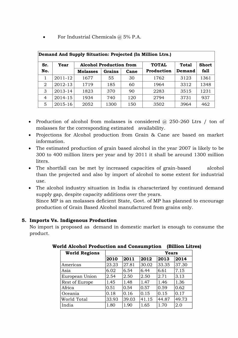
Demand And Supply Situation: Projected (In Million Ltrs.)
Sr.
No.
Year
Alcohol Production from TOTAL
Production
Total
Demand
Short
fall Molasses Grains Cane
1 2011-12 1677 55 30 1762 3123 1361
2 2012-13 1719 185 60 1964 3312 1348
3 2013-14 1823 370 90 2283 3515 1231
4 2014-15 1934 740 120 2794 3731 937
5 2015-16 2052 1300 150 3502 3964 462
Production of alcohol from molasses is considered @ 250-260 Ltrs / ton of
molasses for the corresponding estimated availability.
Projections for Alcohol production from Grain & Cane are based on market
information.
The estimated production of grain based alcohol in the year 2007 is likely to be
300 to 400 million liters per year and by 2011 it shall be around 1300 million
liters.
The shortfall can be met by increased capacities of grain-based alcohol
than the projected and also by import of alcohol to some extent for industrial
use.
The alcohol industry situation in India is characterized by continued demand
supply gap, despite capacity additions over the years.
Since MP is an molasses deficient State, Govt. of MP has planned to encourage
production of Grain Based Alcohol manufactured from grains only.
5. Imports Vs. Indigenous Production
No import is proposed as demand in domestic market is enough to consume the
product.
World Alcohol Production and Consumption (Billion Litres)
World Regions Years
2010 2011 2012 2013 2014
Americas 23.23 27.81 30.02 33.35 37.30
Asia 6.02 6.54 6.44 6.61 7.15
European Union 2.54 2.50 2.50 2.71 3.13
Rest of Europe 1.45 1.48 1.47 1.46 1.36
Africa 0.51 0.54 0.57 0.59 0.62
Oceania 0.18 0.16 0.15 0.15 0.17
World Total 33.93 39.03 41.15 44.87 49.73
India 1.80 1.90 1.65 1.70 2.0

* Projected
Source: F. O. Lichfs World Ethanol and Biofuels Report, Vol.4, No.17, 09/05/2006
Ethyl alcohol is basically used for three purposes i.e. 1) Industrial alcohol for
production of downstream chemicals, 2) Pptable Alcohol for mamifacture of
alcoholic beverages (Country Liquor and IMFL) and 3) Fuel ethanol or
Anhydrous alcohol, which can be blended with petrol or diesel.
Sr. No. Ethanol Consumption for (%)
1 Industrial 21
2 Potable 11
3 Fuel 68
Industrial Alcohol: -
Ethyl Alcohol is an Important feedstock for the manufacture of chemicals.
World ethyl alcohol consumption for the production of chemicals is
around 1%. These chemicals are primarily the basic carbon based products
like Acetic acid, Butanol, Butadiene, Acetic Anhydride, Vinyl Acetate, PVC
etc. The existing plants such as synthetic rubber requiring large quantities
of alcohol will certainly grow to a large capacity. Acetic acid & Butanol,
which are needed in pharmaceuticals, paints & in many other areas are
important industries as they are value added products. Ethylene, Ethylene
oxide & Mono-ethylene glycol are also produced from petrochemical route.
However latest technological development & taking into account the
increasing cost of petrochemical raw material, it is now possible toproduce
Ethylene oxide, Mono-ethylene glycol etc. starting from ethanol.
During the last 5-6 years, a number of alcohol-based industries have come up&
the existing has marginally expanded. The raw material needs of the
alcohol based chemical industry have to be niet to facilitate maximum capacity
utilization of these units in order to meet the domestic demands for the end
products. These units are starving for want of raw materials. The shortage is
wide spread & it has hit a most of chemical drug & other industries. The drug
industry is also bedeviled by scarcity of industrial alcohol. Producers of insulin,
antibiotics, tonics & several other essential bulk drugs & finished formulations
are unable to obtain their quota of industrial alcohol, which is a vital
raw material for them. Thus, even in Maharashtra, which should be a
State with surplus production of alcohol, drug & chemical units are in the
group of acute shortage of industrial alcohol.

It follows that the supply of industrial alcohol to chemical and drugs units in
the country will remain below normal for some more time. In order to
maintain proper rate of growth of industries, production of alcohol must
increase.
6 Export Possibility
The company is setting up grain base RS/ENA plant, to supply the finish goods in
the country at present is no export possibility at this capacity is envisaged.
7 Domestic/Export Markets
As above
8 Employment generation (direct and indirect) due to the project
Existing & Proposed Employment : 132 Nos.
Apart from that indirect employment generation is envisaged from the project.
Total manpower requirement
Sr no. Permanent Staff Existing Proposed for Total configuration of 500 KLD 1. Distillery manager 1 1
2. Production manager 4 4
3. ETP in-charge 1 1
4. Lab chemist 6 6
5. Operators 12 16
6. Project Engineer / Shift Engineer 6 10
7. Electrician 8 10
8. Mechanical fitters 14 18
9. Office Peon 6 8
10. Office assistant 4 6
11. Excise officer 2 2
12. Waterman/ Pump man 6 10
13. Other Contractual staff 30 40
14. Total 100 132
9 Project Description
i. Type of the project including interlinked and interdependent project, if any
No interlinked and interdependent project with the proposed plant. This existing
Co Gen Plant is 4.0 MW whereas proposed Co-gen plant of 06 MW is proposed.
Incineration Boiler of 75 TPH is also proposed for implementation of zero
discharge concept whenever [plant will be operated on Molasses base. CO2 will
also generate as by product from the fermentation process which is turn can be

utilized after further treatment at CO2 plant in industrial or food grade application.
It is also proposed Evaporation plant/ Slope fired Boilers of effluent to provide
better environment conservation and pollution control arrangement in the unit as
well as for the surrounding area.
ii. Location (map showing general location, specific location, and project
boundary & project site layout) with Coordinates:
The unit is spreaded over 160 acres of land in village Sehatganj Tehsil, Raisen
Dist. – Raisen of MP. The latitude and longitude of the site is as below
1. 23°15' 18 "N- 77°38'05"E 2. 23°15' 24 "N- 77°37'55"E
3. 23°15' 27 "N- 77°38'01"E 4. 23°15' 11 "N- 77°37'59"E
A. Satellite Image of the Project area

B. Satellite Image of the Study area
C. Location Map

D. Topographical Base Map
iii. Details of Alternate Site:
The site is proposed on the piece of land where existing distillery unit 120 KLD is
already in operation. The total acquired land is about 160 acres. No additional
land is required for 200 KLD plant as it will be achieved through up gradation in
existing plant of 120 KLD, proposed unit of 300 KLD will require 90 acres of land.
Most of the infrastructure is already available. Therefore proposed site suitable for
the project configuration.

iv. Size Or Magnitude Of Operation:
M/s Som is operating grain & molasses based distillery having capacity of 120
KLD for production of RS/ENA along with 4.0 MW co gen plant , Co2 18,000
MT/Annum. Unit is also having IMFL bottling plant with capacity of 86,400
KL/Annum
The present proposal is for expansion of grain & molasses based distillery from
120 KLD to 200 KLD through up-gradation of existing plant & machineries as
well as addition of new unit of grain & molasses based distillery of 300 KLD .
After expansion, total capacity of the Unit will 500 KLD and will have two units of
200 KLD and 300 KLD for production of RS/ENA/Ethanol/Glycol
v. Project Description With Process Details: The overall process is shown on the attached Block Flow Diagram, and Process
Flow Diagrams. The following describes the production of Rs/ENA/ Ethanol /
Glycol and co-products from grain and molasses .
PROCESS DESCRIPTION FOR GRAIN BASED OPERATION 1. Grain Storage Silos, Cleaning, Handling And Milling Section:
Grain is received from various sources and is pre-cleaned off Stones, husk, straws
and iron metals etc. and then Stored in specially designed Storage Silos. Grains
are continuously lifted from the bottom of the Silos and screened followed by
removal of stones in De-stoner and iron metals in Magnetic Separators. Cleaned
Grains are then milled using dry milling process in Hammer Mills. The flour is fed
through the bucket elevator and conveyed to the Batch Machine through a Screw
Conveyor.
2. Slurry Preparation / Liquefaction
Slurry from pre-masher is taken to Initial liquefaction tank where liquefying
enzyme is added. The mixture of slurry and steam is then passed through the
retention vessel (cook tube) having sufficient capacity to provide the desired
retention time at a given flow rate. The cooked mash is discharged to a flash tank
for liquefaction.
The gelatinized mash from the flash tank is further liquefied in a final liquefaction
tank where liquefying enzyme is added. Then the liquefied mash is passed through
plate heat exchanger and cooled slurry transferred to Fermentation section.
3. Fermentation Section
The purpose of fermentation is to convert the fermentable substrate into alcohol.
At the start of the cycle, the fermenter is charged with mash and contents of the
Yeast Activation Vessel. Significant heat release takes place during fermentation
and Co2 is generated as by Product. This is removed by passing cooling water

through the Fermenter PHE's to maintain an optimum temperature. The
recirculating pumps also serve to empty the fermenter into Beer Well.
5. DistillationSection
Wash to ENA Multi-pressure: -
Pre-heated fermented wash is fed into a series of Distillation Columns to increase
the alcohol concentration and remove various impurities including Fusel oil as by
product .The columns are termed as below:
a. Analyzer
b. Degasifier
c. Pre Rectifier
d. Extractive Distillation
e. Rectifier cum Exhaust
f. Recovery
g. Simmering
ENA drawn from the Simmering Column is taken to the receiver after cooling in
ENA cooler.
5. Evaporation Section
The Spent Wash discharged from the Analyzer column bottom is taken to the
Decanter for separation of suspended solids then thin slop to evaporation section
for concentrating the slop up to 40%w/w solids. Treatment scheme is a series of
evaporation effects working on the principle of falling film Evaporation & Forced
circulation.
6. Dryer Section
The concentrated syrup is mixed with the wet cake from the decantation section
.This mixture is termed as DWGS which either sold as cattle feed or fed in Dryer to
reduce the moisture up to 10%. This by product is termed as DDGS which is in a
powder form.
7. Process Condensate Treatment Section
The process condensate from the evaporation section is partially recycled in
making Grain Slurry and balance qty treated in this unit and this treated
condensate is then recycled back to process thus reducing the fresh water
consumption.
Product Specification Extra Neutral Alcohol (ENA):

S.No Parameter Unit Value
1. Specific Gravity at 15.6 deg C 0.80692
2. Ethanol content at 20 deg C % v/v 96
3. Acid as acetic acid by GC Analysis ppm ≤ 3
4. Butanol ppm Nil 5. Diacetal ppb 200 max
6. Aldehyde as acetaldehyde, ppm <1
7. Esters as ethyl acetate ppm <1
8. Copper ppm Nil
9. Lead as Pb, ppm Nil
10. Methanol ppm <2
11. Furfural ppm Nil
12. N-Propanol & iso-Propanol ppm Nil 13. Dry Extract ppm Negligible
14. Permanganate Time at 15 Deg C IS 1049
minutes 50
Typical DWGS Product Specification
Crude Protein, wt. percent, dry basis, min 30.0
Crude Fat, wt. percent, dry basis, min 6.0
Crude Fiber, wt. percent, dry basis, min 8.5
Ruminant TDN, wt. percent, dry basis, min 88.0
Note: This may vary depending on the quality of raw material.
Process Flow Chart For Grain Based Operation

PROCESS DESCRIPTION FOR MOLASSES BASED OPERATION
FERMENTATION
Molasses, diluted with water to the desired concentration is metered continuously
into a single tank fermenter. Additives likes urea (in the form of pellets or prills)
and defoaming oil are also introduced in the fermenter as required. There is an
automatic foam level sensing and dosing system for defoaming oil.

Every Kilogram of alcohol produced, generates about 290 Kcal of heat. This excess
heat is removed by continuous circulation of fermenting wash through an
external plate heat exchanger called the Fermenter Cooler. The fermenter
temperature is always maintained between 32 and 35 deg. C, the range optimum
for efficient fermentation.
The yeast for the fermentation is initially (i.e. during start-up of the plant)
developed in the Propagation Section described further on. Once propagated, a
viable cell population of about 500 million cells/ml is maintained by yeast
recycling and continuous aeration of the fermenter. Fluctuations in the yeast
count of +/- 20% have little effect on the overall fermenter productivity. Yeast cell
vitality which is usually above 70% may, in times of stress (such as prolonged
shut-downs) drop to 50% without affecting the fermentation.
Fermented wash passes through a series of hydro cyclones (one to three or
move in number depending on plant capacity), which remove grit, iron filings
and similar heavy particulate matter. This rejected material along with some
wash, is taken to the bottom portion of the wash column for alcohol recovery.
The overflow from the first hydro cyclone is taken a wash tank, also provided
with an arrangement to facilitate removal of heavy settable particulate matter.
Overflow from the wash tank is taken to the yeast separator, which clarifies the
wash. The hydro cyclone and the wash tank protect the separator from erosion
damage by removing grit and similar hard particles.
Wash Preparation
For the plant mash, molasses is diluted with water to give a sugar concentration
of 14 to 18% and pumped directly into the fermenter. This mash is usually not
sterilized, although in certain cases it has been pasteurised with a resultant
slight increase in efficiency. The fermenter is issued when it is one eighth to one
fourth full with a large volume of active yeast. 2 to 4% of the final volume to
allow development of the yeast during the entire filling period, which may
amount to 8 hours and to avoid growth of contaminating organisms during
this period.
Nutrients
Blackstrap molasses usually contains enough yeast nutrients to give a fast,
efficient fermentation. In some cases, however, it is desirable to add small
quantities of ammonium salts, such as ammonium sulphate, to the mash to
increase the rate and efficiency of the fermentation. In such cases, the amount
of ammonium sulphate added varies between 0.5 liters and 3 liters per 10,000
liters of mash, depending on the molasses used, the optimum amount being
determined by laboratory in a blackstrap molasses fermentation.

Fermentation Temperatures
Fermenters are usually set at a temperature between 270 C and 300 C and are
held a 320 C by the use of water sprays on the rank internal cooling coils, or by
circulation of the mash through external coolers. It is desirable to maintain the
temperature of the mash below 350 C. The amount of heat liberated during
the fermentation agrees with the theoretical value.
C2H12O 2C2H5OH + 2CO2+26.0 Calories
The heat produced from a fermentation involving 100 kg of sugar is 260 cal.
If the fermenters are not cooled the temperature of the mash will rise as much as
400 C.
• Yeast Recycling:
The yeast in the fermented wash is removed as a 45 to 55 v/v slurry, and is
returned to the fermenter. This feature ensures that a high yeast cell
concentration is achieved and maintained in the fermenter. By recirculating
grown, active yeast, sugar that would have otherwise been consumed in yeast
growth, is made available for alcohol production, ensuring high process
efficiency.
• Propagation:
The propagation section is a feeder unit to the fermenter. Yeast, either
Saccharomyees cereviseae or Schizosaccharomyees (the choice being
determined by other process parameters, mainly the downstream effluent
treatment system) is grown in 3 stages. The first two stages are designed for
aseptic growth. Propagation vessel III develops the inoculum using pasteurized
molasses solution as the medium. This vessel has a dual function. During
propagation, it serves for inoculum build-up. When the fermenter enters the
continuous production mode, Propagation Vessel III is used as an intermediate
wash tank. Propagation is carried out only to start up the process initially or
after very long shut-downs during which the fermenter is emptied.
• CO2 Scrubbing and Recovery:
The carbon-di-oxide produced during fermentation is scrubbed with water in
packed- bed scrubber, to recover alcohol. The water from the scrubber is
returned to the fermenter. About 1.0% of the total alcohol production is saved
by scrubbing the fermenter off gas. In plants where it is desired to recover
carbon-di-oxide, a part of the wash is drawn into a separate vessel and is
aerated there. This external aeration allows the recovery of CO2 uncontaminated
with air. More details of this system can be supplied on request.
• Fermentation Parameters (Typical):

The pH of the fermenter is maintained between 4.0 & 4.8 usually without addition
of any acid. The alcohol concentration is maintained between 7.0 & 7.5 % v/v,
unless a highly concentrate effluent is to be produced. To reduce the effluent
volume, the fermenter is operated at a very high dissolved solids level by
increasing the proportion of weak wash recycle. Under these conditions, alcohol
concentration is reduced to between 5.5 to 6.0% v/v.
Conversion of sugar to alcohol is instantaneous, and the residual sugar
concentration is maintained below 0.2 % w/w as glucose. This usually
corresponds to a residual reducing substances concentration of 2.0 to 2.5 %
w/w in wash.
All the nutrient elements necessary for yeast growth exist in adequate quantities
as impurities in molasses. Occasionally, Nitrogen may have to be supplemented.
Defoaming oil (DFO), say Turkey Red Oil is added to the fermenter by an
automated DFO dosing system, to control foaming. Usually no other additives are
required.
• Flexibility:
This process accords tremendous flexibility to the operator. Process conditions
and plant design can be varied to suit individual requirements of alcohol quality,
effluent concentration and characteristics. This unit can give spent wash
suitable for use in any effluent treatment process.
2. Distillation:
Clarified or de-yeasted wash flows by gravity to the propagation vessel No. III,
which during continuous production, operates as an intermediate wash tank.
From here, fermented wash is pumped to the wash preheater, which uses vapors
from the rectifying column to preheat wash. Further heating is done in an
exchange of heat with weak wash and spent wash (see flow sheet for primary
distillation). Preheated wash then enters the degasifying column of the
distillation section.
• Primary Distillation: The CO2 and the degasifying section help remove the CO2
and other non-condensable entrained in the wash. The wash column is first
column in the distillation section. It is also called the analyzer. Wash is boiled in
this column with steam either supplied as live steam from the boiler (after
pressure reduction and desuperheating) or from a reboiler which generates
steam by evaporating effluent wash.
Alcohol in wash vapourises and is carried, along with water vapor, to the top of
the wash column from where it goes to the rectification column. As wash travels
down the analyzer, it is progressively ‘stripped’ of its alcohol content. At a
point in the column, where the alcohol concentration is 0.5 to 1.0% v/v, a
portion of the wash is drawn off. This is called weak wash.
• Weak Wash Recycling :

Weak wash recycling of weak wash helps maintain the desired level of
dissolved solids in the fermenter, so that an adequately high osmotic pressure
is achieved. Osmotic pressure and the concentration of alcohol in the fermenter,
together keep off infection and minimize sugar losses. Weak wash recycling also
reduces the quantity of effluent spent wash and reduces the process water
requirement of the plant.
Spent wash is the wash from which all alcohol has been removed, this emerges
from the bottom of the wash column at about 105 deg C. Some of the heat is
recovered to preheat fermented wash entering the degasifying column.
Spent wash may also be passed through a forced circulation reboiler to
generate vapors. This concentrates the effluent and reduces the volume further.
Multi Pressure Vacuum Distillation:
After fermentation the next stage in the manufacture of alcohol is to separate
alcohol from fermented wash and to concentrate it to 95% alcohol called as
rectified spirit. For this purpose, distillation process is employed.
Distillation step consumes a considerable amount of energy and is also a
deciding factor in the quality of ENA produced. Hence, in line with the demand of
the industry, efforts have always been to minimize requirement of energy and to
improve the basic quality of alcohol produced. Ease of operation, reliability,
lower down time and flexibility of operations are other parameters considered
during the design.
Three basic types of plant are designed:
a) One is to produce primary quality of alcohol, usually referred to as 'Rectified
Spirit' (R.S.) from the fermented wash. Such plants are also referred to as
‘Primary distillation’ plants.
b) Second is to produce fine quality of spirit usually referred to as 'Extra Neutral
Alcohol' (ENA) starting from R.S. Such plants are also referred to as 'secondary
distillation' plants.
c) Third is to directly produce fine quality alcohol (ENA) from fermented wash.
Such plants are referred to as 'wash (mash) to ENA' plants, where the two steps
of primary and secondary distillation are combined. Such plants usually have
lower consumption of energy than two separate plants
Multi-pressure vacuum distillation system for production of Rectified Spirit
/ ENA consists of following distillation columns namely
1. Degasifying cum analyzer column – Operation under vacuum
2. Pre-rectification column – Operation under vacuum
3. Rectification cum Exhaust Column - Operated under pressure
4. Recovery column - Operated under atmospheric
5. Extractive distillation column – Operated under vacuum
6. Simmering column – Operated under atmospheric
Benefits of Pressure Vacuum Distillation: -
Following are the advantages of pressure vacuum distillation.
• Since the analyzer column operates under vacuum, the formation of byproducts
such as acetal may minimize there by improvement in quality of alcohol.
• Pre-rectification column ensure removal of sulfur compounds/mercaptans and
also reduces load of lower boiling volatile compounds passing on to Rectifier cum
exhaust column.
• The chances of scaling due to invert solubility of certain precipitating inorganic
salts are minimized in vacuum distillation.
• Vacuum distillation requires low steam consumption with re-boiler
Integrated Multi-products Concept: -
It is now possible to install a distillation system, which can produce different
products. In the proposed scheme; the production of rectified spirit have been
considered. This allows flexibility of operation and various products can be
manufactured depending on the market demand. This integrated multi-product
system involves less capital investment as compared to independent system.
In this type of system, switching over from one product to another is quite easy
and there is no chance of contamination of one product with another. The system
can work under multi-pressure principle with few columns operating under
vacuum and few under pressure/atmospheric.
3. Dehydration of Alcohol: Molecular Sieve:
The process drives the rectified feed though a bed of desiccant beds. To allow for
bed regeneration in continuous operation, twin beds are provided of which one
is in dehydration mode while the other is regenerating. Depending on feed
and product specifications, the dehydration-regeneration process releases the
adsorbed water together with contained ethanol, it is recycled back to
regeneration column for reprocessing.
The feed is pumped to regeneration column after preheating in feed preheater.
The overhead vapor of regeneration column is superheated to the required
operating temperature and circulated to sieve bed 1 assumed in the description to
be in dehydration mode. After passing though the desiccant, the vapor is
condensed, cooled and sent to storage.
A small portion of the product vapor is sent, under high vacuum, through bed
2, in regeneration mode, to prepare the desiccant for cycle changeover when bed 2
goes online. The regeneration operation forces the release of the moisture from

the desiccant, making the bed 2 ready for the next cycle. The recovered low
strength vapors are condensed and recycled back to the Regeneration column.
4. Evaporation for Spent wash Treatment
As per recent Environmental Protection Norms from Ministry of Environment
and Forests (MoEF), it is Corporate Responsibility to achieve Zero Discharge in
Inland Surface Water. For 120/200/300 KLPD distillery plant nearly about 1200
, 2000, 3000 M3/Day Raw spent wash is/will produced. Considering the large
volume of spent and achieve Zero liquid discharge plant operation following three
stage process is proposed.
Multi pressure distillation – In this steam is utilized in direct way for heating.
Hence, spent wash quantity generated is less as compared to traditional
distillation technology. Integrated and Standalone Multi effect evaporation - The
spent wash evaporation technology is a multiple effect evaporator system in which
heat recovered from one effect is used to concentrate spent wash in second effect
evaporator with continuous recirculation of concentrated spent wash within the
system until desired concentration is obtained. This entire concentration process
is carried out under vacuum leading to less consumption of steam and maximum
concentration of spent wash with in less period of time. This is the 3rd stage of
effluent treatment wherein spent wash after integrated evaporation is
concentrated and used in incineration boiler.
5. Spent wash Incineration Technology:
After spent wash evaporation, concentrated spent wash with desired
concentration is obtained is feed to incineration type of boiler. The
concentrated spent wash generated after entire process of evaporation is then
sprayed in a furnace with auxiliary fuel such as coal and is then burnt in a
boiler.
6. Process Condensate Treatment and Recycle:
The condensate polishing unit is also envisaged to take care of spent lees, cooling
tower blow down, washing and process condensate from evaporation plant. After
treatment all the stream at CPU, treated condensate can be recycled to process
for dilution and as cooling tower make up and will achieve zero liquid discharge
(ZLD) Due to recycle of process condensate back to process, fresh water demand
can be reduced at large extent
Process flow diagramme ( Molasses Based )

Existing & Proposed Co-generation Power Plant [4.0 & 6.0 MW]
Proposed 6 MW co-generation plant consists of high pressure AFBC water tube
steam boiler & back pressure steam turbine. Fuel in the steam boiler will be burnt
with the help of air in the boiler furnace. Water will be circulated in the boiler
drum and tubes thus getting heated by the flame burning in the boiler furnace.
Water comes out of the boiler drum located at the top of the boiler as steam. Flue
gases rise in the boiler furnace and come in contact with the steam coming out of
boiler drum. Steam after coming in contact with flue gases gets heated up further
thus getting superheated. Super heated steam leaves the boiler in a pipe. Flue
gases after super heating the steam pass through economizer where they pre-heat
the boiler feed water before it enters the boiler drum. After economizer, flue gases
pass through air pre-heaters where they heat the air which is fed to the boiler
furnace for burning the fuel. After air pre heaters flue gases pass through a bag
house filter where the dust particles are collected in filter bags & discharge from
the bottom of the bag house filter. Dust will be collected in the Ash Silo through
pneumatic conveying system.
High pressure superheated steam from boiler is passed through a steam turbine
and low pressure goes to Low pressure header, which is used for distillery. While
passing through the turbine, the high pressure and temperature steam rotates the
turbine rotor and an electric alternator mounted on the same shaft. Electric power
is generated by the alternator. This electric power generated is consumed in house
i.e. for running the distillery and utilities like boilers auxiliaries etc.

Process Flow Chart of Exiting project of 120 KLD (CPP)
Power
Steam
To MEE Plant
DWGS
To Distillation
To Hydro heater/Jet cooker
Working Pressure
3.5 Kg/Cm2
(g)
Working Pressure
3.5 Kg/Cm2
(g)
BOILER – 40 TPH
Pressure – 45 Kg/Cm2
(g)
Temp – 400º C ± 05º C
Turbine 4 MW
Exhaust Steam Header
Pressure 4.0 Kg/Cm2(g)
11 KV Voltage
Alternator
Sub Station Step down
Transformer
Power Control
Circuit Panel
Motor Control Circuit Panel
Field Equipment

Process Flow Chart of proposed project of 200 KLD (CPP)
Power
Steam
To MEE Plant
DWGS
To Distillation
To Hydro heater/Jet cooker
Working Pressure
3.5 Kg/Cm2
(g)
Working Pressure
3.5 Kg/Cm2
(g)
BOILER – 40 TPH
Pressure – 45 Kg/Cm2
(g)
Temp – 400º C ± 05º C
11 KV Voltage
Alternator
Sub Station Step down
Transformer
Power Control
Circuit Panel
Turbine 4 MW
Exhaust Steam Header
Pressure 4.0 Kg/Cm2(g)
Motor Control Circuit Panel
Field Equipment

Process Flow Chart of proposed project of 300 KLD (CPP)
Power
Steam
To MEE Plant
DWGS
To Distillation
To Hydro heater/Jet cooker
Working Pressure
3.5 Kg/Cm2
(g)
Working Pressure
3.5 Kg/Cm2
(g)
Quantity of Raw Materials Required;
Raw Material Quantity Per Day Source
Mode of
Transportat
ion
For 120 KLD For 200 KLD
120+80 KLD
For 300
KLD Total
Grain / Flour
300 MT 500 MT 750 MT 1250
MT
Local Anaj
Mandi /
Private
Supplier
Trucks
Molasses 480 MT 800 MT 1200 MT 2000
MT
Sugar Mills By Road
Tankers
BOILER – 75 TPH
Pressure – 45 Kg/Cm2
(g)
Temp – 400º C ± 05º C
Turbine 6 MW
Exhaust Steam Header
Pressure 4.0 Kg/Cm2(g)
11 KV Voltage
Alternator
Sub Station Step down
Transformer
Power Control
Circuit Panel
Motor Control Circuit Panel
Field Equipment

Coal 60 MT 95 MT 125 MT
220
MT
Local
supplier /
Private
Supplier
Trucks
Antifoam Agent In Mol-
200 kg/ltr
In Grain-
100 kg/ltr
In Mol-
333 kg/ltr
In Grain-
166 kg/ltr
In Mol-
500 kg/ltr
In Grain-
250 kg/ltr
Bhopal Tanker /
Drums or Barrels in
Trucks/Mini
Trucks
NaOH (50%) In Mol-
350 kg/ltr
In Grain-
350 kg/ltr
In Mol-
583 kg/ltr
In Grain-
583 kg/ltr
In Mol-
875 kg/ltr
In Grain-
875 kg/ltr
Bhopal Trucks /
Drums or
Barrels in Trucks/Mini
Trucks
Phosphoric acid
(75%0 - - -
Bhopal Mini Truck
Enzymes like
Liquizime Mol- Nil
Grain-100 kg
Mol- Nil
Grain-166 kg
Mol- Nil
Grain-250
kg
Enzymes like
Spzyme Mol- Nil Grain-120 kg
Mol- Nil Grain-200 kg
Mol- Nil
Grain-300 kg
Yeast (In Grain
Only) 40 kg 66 kg 100 kg
Bhopal Mini Truck
Urea (In Molasses) 375 Kg 625 Kg 937 Kg
Alcorise Biocide (In
Molasses) 9 kg 15 kg 22 kg
vii. Resource optimization/ recycling and reuse
Advantages of Grain Plant over the Molasses Plant
1. Water consumption is reduced by 30 to 40% % in the system adopted for MEE,
CPU and Slope fired boiler
2. Effluent generation is also reduced by 30% in the Grain based plant as
compare to Molasses based plant
3. Hydraulic Load is also reduced by 40-50%
4. By adaptation of such technology for production of ENA , reduction in pollution load
is proven fact..
• Centrifuge Decanter is used for separation of suspended solid from the spent wash
coming out of the distillation plant when plant is operated on grain basiselse MEE
followed by slope fired boiler will be used when plant will be operated on Molasses
basis.
• Wet cake has 30-35% w/w solids as removed from the bottom of the Decanter.
Thin slops coming out from decanter will be collected in a tank & transferred for
the partial recycling & remaining for Evaporation. The separated solid shall be
converted as DWGS, which is protein reach cattle feed having good market value.
The ash generated form incinerator boiler is rich in potash content and having
good value to be used as manure in the field.

Multi Pressure Distillation system has lower steam consumption as it is designed
for maximum heat integration to conserve energy.
Energy efficient Multi-Pressure Distillation system with a Steam Consumption 16
TPH for spirit only of Total Spirit (depending on mode of operation).
Vacuum operation nearly eliminates scaling problem in Analyzer Column and
ensures better separation of impurities, which results into better quality product.
Well-engineered Plants with high efficiency trays to ensure elaborate separation
and removal of impurities ensuring superior quality of Extra Neutral Alcohol.
Analyzer Column with Hyper-stat Rh-Grid trays ensure high turbulence on tray,
this minimizes chances of scaling. Also, this special construction of trays and
accesNos to each tray helps in easier cleaning column internals.
Condensers are designed with multiple passes to ensure high velocity and to
minimize scaling inside tubes.
viii.: Availability of Water its source, energy / power requirement and source:
Water requirement:
Construction Phase – 20-30 kld
Operational Phase – Water requirement for the existing and proposed project is ass
follows :
Feed Stock Molasses Grain
S
No
Plat
Capacity
KLD
Description Water
Requirement
without
recycle in KLD
Water
Requirement
with recycle
in KLD
Water
Requirement
without
recycle in KLD
Water
Requirement
with recycle
in KLD
1 120 Process water 1075 200 728 12
Soft water 862 455 810 622
DM water 1232 278 1274 363
Total water 3169 933 2812 997
Water
Requirement
Kl/KL
26.4 7.8 23.4 8.3
2 200 Process water 1765 313 1175 11
Soft water 1430 771 1345 1026
DM water 2050 464 2120 604
Total water 5245 1548 4640 1641
Water
Requirement Kl/KL
26.2 7.7 23.2 8.2
3 300 Process water 2625 486 1736 8
Soft water 2140 1152 2013 1537
DM water 3072 691 3176 901
Total water 7837 2311 6925 2446
Water
Requirement
Kl/KL
26.1 7.7 23.1 8.15
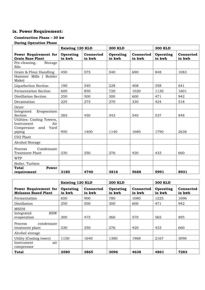
ix. Power Requirement:
Construction Phase – 30 kw
During Operation Phase
Power Requirement for
Grain Base Plant
Existing 120 KLD 200 KLD 300 KLD
Operating
in kwh
Connected
in kwh
Operating
in kwh
Connected
in kwh
Operating
in kwh
Connected
in kwh
Pre-cleaning, Storage
Silo
Grain & Flour Handling 450 575 540 690 848 1083
Hammer Mills ( Buhler
Make)
Liquefaction Section 190 340 228 408 358 641
Fermentation Section 600 850 720 1020 1130 1601
Distillation Section 250 500 300 600 471 942
Decantation 225 275 270 330 424 518
Dryer
Integrated Evaporation Section 285 450 342 540 537 848
Utilities: Cooling Towers,
Instrument Air
Compressor and Yard
piping 950 1400 1140 1680 1790 2638
C02 Plant
Alcohol Storage
Process Condensate Treatment Plant 230 350 276 420 433 660
WTP
Boiler, Turbine
Total Power
requirement 3180 4740 3816 5688 5991 8931
Power Requirement for Molasses Based Plant
Existing 120 KLD 200 KLD 300 KLD
Operating in kwh
Connected in kwh
Operating in kwh
Connected in kwh
Operating in kwh
Connected in kwh
Fermentation 650 900 780 1080 1225 1696
Distillation 250 500 300 600 471 942
MSDH
Integrated RSW
evaporation 300 475 360 570 565 895
Process condensate
treatment plant 230 350 276 420 433 660
Alcohol storage
Utility (Cooling tower) 1150 1640 1380 1968 2167 3090
Instrument air
compressor
Total 2580 3865 3096 4638 4861 7283

During operation phase , the required power will be taken from cogeneration
power plant. Details of co gen plant and turbine is a s follws :
Turbine for Existing Co-Generation Power Plant of 4 MW for 120 KLD
Parameters Details
Turbine Back Pressure Type
Back Pressure 4.0 kg/cm²
Turbine RPM 7500
Capacity 4.0 MW
Alternator 4.0 MW
Turbine Efficiency 90 %
Alternator Efficiency 85 %
Turbine for Co-Generation Power Plant of 4 MW for 200 KLD
Parameters Details
Turbine Back Pressure Type
Back Pressure 4.0 kg/cm²
Turbine RPM 7500
Capacity 4.0 MW
Alternator 4.0 MW
Turbine Efficiency 90 %
Alternator Efficiency 85 %
Turbine for Proposed Co-Generation Power Plant of 6 MW for 300 KLD
Parameters Details
Turbine Back Pressure Type
Back Pressure 4.0 kg/cm²
Turbine RPM 7500
Capacity 4.0 MW
Alternator 4.0 MW
Turbine Efficiency 90 %
Alternator Efficiency 85 %
Existing DG set of 3000 KVA is kept as standby arrangement. For capacity
expansion same arrangements are proposed.
Details of DG
S. No. Details
Existing Proposed
1. Type of Fuel HSD HSD
2. Capacity 500 KVA X 6 NOS SAME
3. Stack Height 5 MTR 5 MTR
4. Pollution Control Equipment Measures
Adequate stack height/ Acoustic
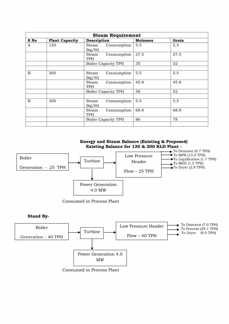
Steam Requirement
S No Plant Capacity Description Molasses Grain
A 120 Steam Consumption
(kg/lit)
5.5 5.5
Steam Consumption TPH
27.5 27.5
Boiler Capacity TPH 35 32
B 200 Steam Consumption
(kg/lit)
5.5 5.5
Steam Consumption
TPH
45.8 45.8
Boiler Capacity TPH 58 52
B 300 Steam Consumption
(kg/lit)
5.5 5.5
Steam Consumption
TPH
68.8 68.8
Boiler Capacity TPH 86 78
Energy and Steam Balance (Existing & Proposed) Existing Balance for 120 & 200 KLD Plant -
To Dearator (0.7 TPH) To MPR (13.0 TPH) To Liquification (1.7 TPH) To MEE (1.5 TPH) To Dryer (2.8 TPH)
Consumed in Process Plant
Stand By- To Dearator (7.0 TPH) To Process (29.1 TPH) To Dryer (9.0 TPH)
Consumed in Process Plant
Boiler
Generation - 25 TPH
Pressure - 45
Kg/Cm2(g)
Turbine
Low Pressure
Header
Flow – 25 TPH
Pressure – 3.5
Kg/Cm2(g) Power Generation
4.0 MW
Boiler
Generation - 40 TPH
Pressure - 67
Kg/Cm2(g)
Turbine
Low Pressure Header
Flow – 40 TPH
Pressure – 4.0
Kg/Cm2(g) Power Generation 4.0
MW

Proposed Balance for 300 KLD- To Dearator (7.0 TPH) To Process (29.1 TPH) To Dryer (9.0 TPH)
Consumed in Process Plant
X. Quantity of wastes to be generated (liquid and solid) and Scheme for their
management/ disposal
For Liquid Waste
Following are details of spent wash and process condensate generation for
existing and proposed configuration .
Spent Wash Generation to MEE
S
No
Plant Capacity
KLD
Description Molassees Grain
A 120 Raw Spent
Wash/Thin Slop -
TPD
Raw Spent
wash : 1308
Conc Spent wash : 158
511
Solid In spent wash
-%w/w
14 7.77
Conc Product –TPD 305.2 113
Solid in Conc
product -% w/w
60 35
Evaporation duty
TPD
1002.8 398
B 200 Raw Spent
Wash/Thin Slop -TPD
Raw Spent
wash : 2179 Conc Spent
wash : 264
853
Solid In spent wash
-%w/w
14 7.77
Conc Product –TPD 508.4 189
Solid in Conc
product -% w/w
60 35
Evaporation duty
TPD
1670.6 664
C 300 Raw Spent Wash/Thin Slop -
TPD
Raw Spent wash : 3268
Conc Spent 3sh
: 396
1280
Solid In spent wash
-%w/w
14 7.76
Boiler
Generation - 75 TPH
Pressure - 67
Kg/Cm2(g)
Turbine
Low Pressure Header
Flow – 75 TPH
Pressure – 4.0
Kg/Cm2(g) Power Generation
6.0 MW
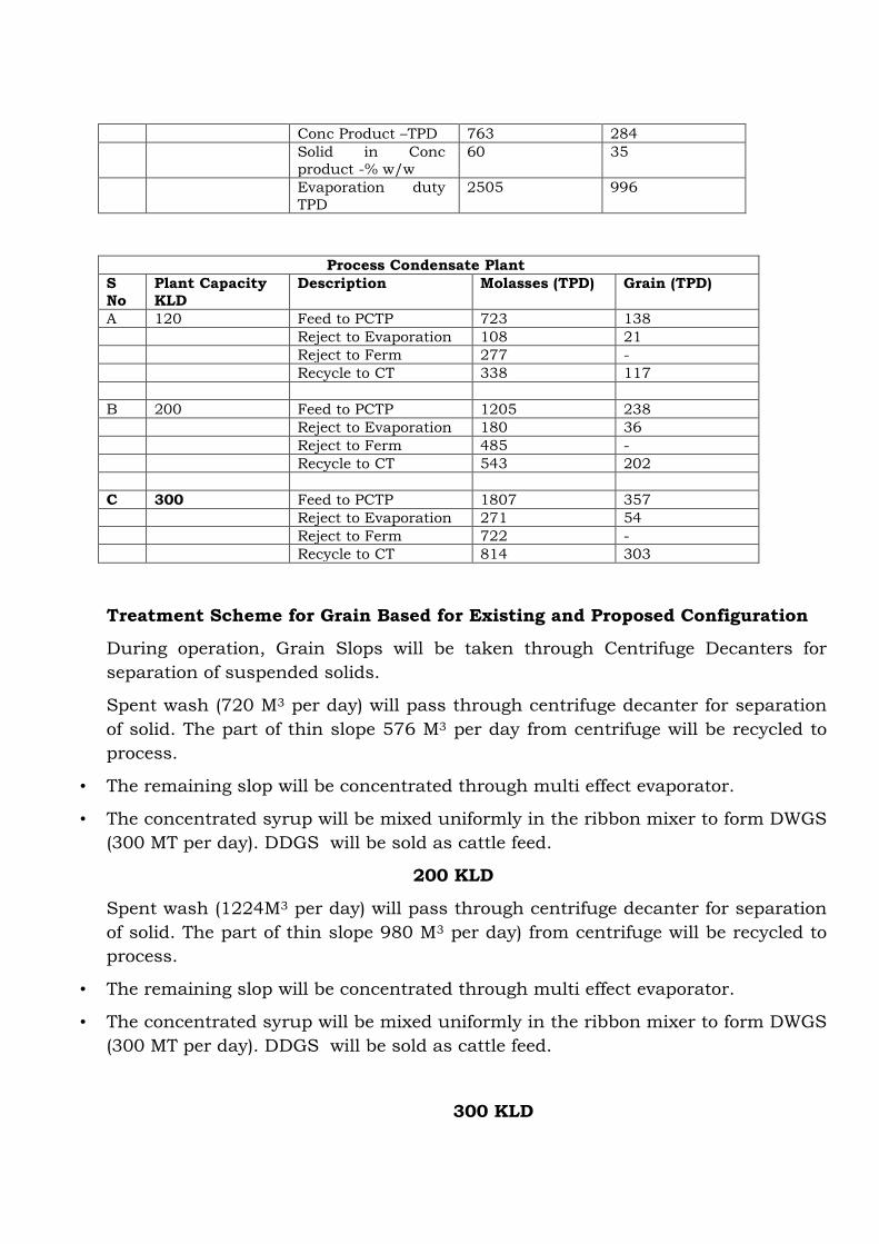
Conc Product –TPD 763 284
Solid in Conc
product -% w/w
60 35
Evaporation duty
TPD
2505 996
Process Condensate Plant
S
No
Plant Capacity
KLD
Description Molasses (TPD) Grain (TPD)
A 120 Feed to PCTP 723 138
Reject to Evaporation 108 21
Reject to Ferm 277 -
Recycle to CT 338 117
B 200 Feed to PCTP 1205 238
Reject to Evaporation 180 36
Reject to Ferm 485 -
Recycle to CT 543 202
C 300 Feed to PCTP 1807 357
Reject to Evaporation 271 54
Reject to Ferm 722 -
Recycle to CT 814 303
Treatment Scheme for Grain Based for Existing and Proposed Configuration
During operation, Grain Slops will be taken through Centrifuge Decanters for
separation of suspended solids.
Spent wash (720 M3 per day) will pass through centrifuge decanter for separation
of solid. The part of thin slope 576 M3 per day from centrifuge will be recycled to
process.
• The remaining slop will be concentrated through multi effect evaporator.
• The concentrated syrup will be mixed uniformly in the ribbon mixer to form DWGS
(300 MT per day). DDGS will be sold as cattle feed.
200 KLD
Spent wash (1224M3 per day) will pass through centrifuge decanter for separation
of solid. The part of thin slope 980 M3 per day) from centrifuge will be recycled to
process.
• The remaining slop will be concentrated through multi effect evaporator.
• The concentrated syrup will be mixed uniformly in the ribbon mixer to form DWGS
(300 MT per day). DDGS will be sold as cattle feed.
300 KLD

Spent wash (1836 M3 per day) will pass through centrifuge decanter for separation
of solid. The part of thin slope 1469 M3 per day) from centrifuge will be recycled to
process.
• The remaining slop will be concentrated through multi effect evaporator.
• The concentrated syrup will be mixed uniformly in the ribbon mixer to form DWGS
(300 MT per day). DDGS will be sold as cattle feed.
Treatment Scheme
Decantation Section
• Centrifuge Decanter is used for separation of suspended solid from the spent wash
coming out of the distillation plant.
• Wet cake has 30-35% w/w solids as removed from the bottom of the Decanter.
• Thin slops coming out from decanter will be collected in a tank & transferred for
the partial recycling & remaining for Evaporation.
Evaporation section
The suggested treatment scheme is a Multi Effect Evaporator with thermal
recompression for Thin Slops Evaporation. The following points will elucidate the
basic working principal:
• Shell & Tube type Evaporators with highly efficient liquid distributor working on
the principal of Falling Film Evaporation.
• Analyzer vapors are fed to the 1st effect evaporator shell side at the given pressure
& temperature as the heating medium.
• The Feed is fed from the top of the 1st effect evaporator which is Falling Film
Evaporator-1
• Vapors generated in the 1st effect VLS (Vapour Liquid Separator) are used as heat
source in the 2nd effect. 3rd effect(finisher) is on steam.Vapours generated in the
2nd & 3rd effects VLS are condensed on shell side of Surface Condenser for
Evaporator.
• The Total Solid will be obtained at the outlet of the 3rd effect evaporator. A shell &
tube type multi pass surface condenser is employed for condensing the shell side
vapors.
• The operation of the plant will be under vacuum. Vacuum will be created with the
help of a water ring vaccum pump. Cooling water from the cooling tower is used
in the surface condensers for condensing the vapors.
• Lees of 100 m3/day is recycled back for Molasses dilution . Balance 100 m3/day
lees sent to CT make up after heat recovery. 600 m3/day of Process condensate is
fed to PCTP unit.
3. 510 m3/day treated water will return back to process for utilization in
liquefaction/fermentation/cooling tower etc.

4. Rainwater will be utilized to recharge the underground resource through
scientifically designed rainwater harvesting system.
5. 7 M3/day of boiler blow down will be sent for ash quenching.
Treatment Scheme for Molasses Based for Existing and Proposed
Configuration
Spent wash Incineration Technology:
After spent wash evaporation, concentrated spent wash with desired concentration is
obtained is feed to incineration type of boiler. The concentrated spent wash generated
after entire process of evaporation is then sprayed in a furnace with auxiliary fuel such
as coal and is then burnt in a boiler.
Integrated and Standalone Multi effect evaporation - The spent wash evaporation
technology is a multiple effect evaporator system in which heat recovered from one effect is
used to concentrate spent wash in second effect evaporator with continuous
recirculation of concentrated spent wash within the system until desired concentration is
obtained. This entire concentration process is carried out under vacuum leading to less
consumption of steam and maximum concentration of spent wash with in less period of
time. This is the 3rd stage of effluent treatment wherein spent wash after integrated
evaporation is concentrated and used in incineration boiler.
The concentrated spent wash generated after entire process of evaporation is then
sprayed in a furnace with baggass as support fuel and is then burnt in a boiler. Som
proposes to employ spent wash Concentration and Incineration Technology,
simultaneously generating Steam and Power required for the Distillery process. With
effective utilization of such a technology, major hurdle of spent wash disposal will be
solved and the propose distillery will become a ZLD unit
Process Condensate Treatment and Recycle:
The condensate polishing unit is also envisaged to take care of spent lees, cooling tower
blow down, washing and process condensate from evaporation plant. After treatment the
entire stream at CPU, treated condensate can be recycled to process for dilution and as
cooling tower make up and will achieve zero liquid discharge (ZLD) Due to recycle of
process condensate back to process, fresh water demand can be reduced at large extent

Solid And Hazardous Waste Management
Solid Waste Management
S
No
Plant Capacity
KLD
Description Molasses (TPD) Grain (TPD)
A 120 DWGS - 300
Boiler ash (Coal Ash) 21 45
Waste papers/Boxes
Yeast Sludge NIL NIL
Lime Sludge NIL NIL
WTP Sludge NIL NIL
ETP Sludge -
Incinerated Ash 40 -
B 200 DWGS - 500
Boiler ash (Coal Ash) 35
Waste papers/Boxes
Yeast Sludge NIL NIL
Lime Sludge NIL NIL
WTP Sludge NIL NIL
ETP Sludge
Incinerated Ash 66

C 300 DWGS - 800
Boiler ash (Coal Ash) 61 131
Waste papers/Boxes
Yeast Sludge NIL
Lime Sludge NIL
WTP Sludge NIL
ETP Sludge
Incinerated Ash 116
4.0 Site Analysis:
i. Connectivity
Location : Own land at Village Sehatganj
Tehsil –Sanchi, District- Raisen (MP)
Khasara No : 76/1,2,3 , 77/1, 77/2, 76/4
Details of Environmental Settings
S. No. Particulars Details
1. Locations
A. Village Sehatganj
B. Tehsil Sanchi
C. District Raisen
D. State Madhya Pradesh
Toposheet No. 55-E/11 & 55-E/12
2. General ground level 445-439m above MSL
3. Nearest National/ State Highway Bhopal- Sagar National Highway-86 – 0.01km- N
4. Nearest Railway Station Habibganj – 20km Bhadbhada Ghat – 16.50km
5. Nearest Airport Bhopal – 30.75km
6. Nearest Religious place Kankali Mandir- 6.25km- SW
7. Archaeological Important Place None within 10km radius
8. Ecological Sensitive Areas (Wild Life Sanctuaries)
None within 10km radius
9. Reserved / Protected Forest within 10km radius
Raisen RF - 0.50km - NE Goharganj RF - 0.25km - S Bilarkhoh PF - 0.75 km - W Bhopal RF - 5.00km - W
10. Nearest major city >50000 population
None
11. Nearest Town/City within 10km radius
Bhopal – 13.00 km
12. Dist. Head quarter Raisen- 15.50km
13. Other Industry within 10km radius Pipalkhiriya Industrial Area- 1.00km- E
14. Surrounding village within 1 km area of the project.
Sehatganj – 0.5km – N Pipalkhiriya – 0.75km- E
15. Nearest village Sehatganj – 0.5km – N
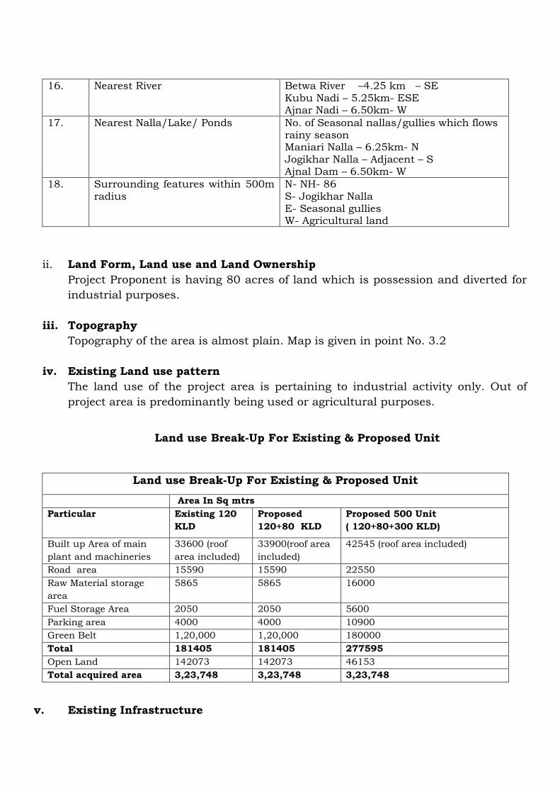
16. Nearest River Betwa River –4.25 km – SE Kubu Nadi – 5.25km- ESE Ajnar Nadi – 6.50km- W
17. Nearest Nalla/Lake/ Ponds No. of Seasonal nallas/gullies which flows rainy season Maniari Nalla – 6.25km- N Jogikhar Nalla – Adjacent – S Ajnal Dam – 6.50km- W
18. Surrounding features within 500m radius
N- NH- 86 S- Jogikhar Nalla E- Seasonal gullies W- Agricultural land
ii. Land Form, Land use and Land Ownership
Project Proponent is having 80 acres of land which is possession and diverted for
industrial purposes.
iii. Topography
Topography of the area is almost plain. Map is given in point No. 3.2
iv. Existing Land use pattern
The land use of the project area is pertaining to industrial activity only. Out of
project area is predominantly being used or agricultural purposes.
Land use Break-Up For Existing & Proposed Unit
Land use Break-Up For Existing & Proposed Unit
Area In Sq mtrs
Particular Existing 120
KLD
Proposed
120+80 KLD
Proposed 500 Unit
( 120+80+300 KLD)
Built up Area of main
plant and machineries
33600 (roof
area included)
33900(roof area
included)
42545 (roof area included)
Road area 15590 15590 22550
Raw Material storage
area
5865 5865 16000
Fuel Storage Area 2050 2050 5600
Parking area 4000 4000 10900
Green Belt 1,20,000 1,20,000 180000
Total 181405 181405 277595
Open Land 142073 142073 46153
Total acquired area 3,23,748 3,23,748 3,23,748
v. Existing Infrastructure

The required infrastructure is already in place as proposed site is in operation.
State Highway is passing at 50 mtrs from the industry.
vi. Soil Classification
The soils in the area are generally of sedimentary type soil.
vii. Climate data from Secondary Source:
Meteorological data month of 15th March, 14 to 14th April, 2017
Date
Temperature OC Relative
Humidity %
Morning
km/hr 8.00hr
Evening
km/hr
17.00hr
Cloudiness
%
Max Avg Min Max Avg Min Wind Dirt
Wind Speed
Wind Dirt
Wind Speed
Mor Eve
15 35 27 18 64 48 32 SE 7.4 WNW 14.8 10 -
16 34 27 19 66 45 30 E 5.6 NE 9.3 - -
17 37 28 19 51 40 29 SE 14.8 WNW 24.1 - -
18 35 28 22 51 38 30 C 0 WSW 18.5 10 -
19 33 24 16 61 40 27 ENE 14.8 WNW 14.8 - -
20 34 26 17 55 36 23 SE 11.1 WNW 22.2 - 10
21 35 26 16 71 37 21 S 9.3 W 27.8 - -
22 34 25 16 64 43 28 WSW 7.4 NW 14.8 - -
23 36 26 17 61 41 30 NNW 3.7 WSW 3.7 10 -
24 36 28 19 55 39 20 SE 9.3 WSW 18.5 20 -
25 36 29 22 60 32 12 C 0 C 0 - 30
26 36 28 19 37 24 9 WNW 14.8 W 18.5 - -
27 38 29 21 41 27 11 SSE 7.4 WNW 22.2 - -
28 38 29 19 41 24 11 N 5.6 W 18.5 10 -
29 38 30 22 32 19 10 NW 14.8 WSW 20.4 - -
30 38 29 20 30 20 9 NW 14.8 W 18.5 - 10
31 37 29 21 48 23 11 ENE 18.1 W 18.5 - -
1 36 28 19 39 19 9 WNW 9.3 W 22.8 - -
2 36 28 19 27 18 10 W 18.5 WSW 11.1 - -
3 37 29 21 39 22 12 WNW 18.5 NNW 14.8 - -
4 37 29 22 35 22 12 C 0 NW 5.6 - -
5 39 30 21 38 20 7 S 14.8 WSW 11.1 10
6 39 30 21 33 18 11 NNW 14.8 WSW 22.8 -
7 38 30 23 30 21 12 C 0 C 0 -
8 37 29 22 33 25 13 C 0 C 0 -
9 37 29 21 47 22 8 E 5.6 WNW 18.5 -
10 37 28 19 33 18 10 NE 9.3 WSW 9.3 -

11 37 28 19 35 19 10 NNE 7.4 SW 11.1 -
12 37 28 18 31 18 7 C 0 SSE 9.3 -
13 38 30 21 35 22 10 SE 7.4 SSW 5.6 - -
14 39 30 21 39 27 13 S 18.5 SW 9.3 - -
Meteorological data month of 15th April, to 14th May, 2017
Date
Temperature OC Relative
Humidity %
Morning km/hr
8.30hr
Evening km/hr
17.30hr
Cloudiness
%
Max Avg Min Max Avg Min Wind
Dirt
Wind
Speed
Wind
Dirt
Wind
Speed Mor Eve.
15 39 30 22 42 25 13 SW 7.4 W 9.3 - -
16 40 32 25 31 21 12 WSW 5.6 NNW 18.5 - -
17 39 31 24 48 29 15 C 0 C 0 - -
18 39 31 23 44 32 14 C 0 C 0 40 40
19 35 29 23 56 36 25 WSW 9.3 ENE 11.1 - -
20 36 29 22 56 35 19 NE 5.6 SSE 13.0 - -
21 37 29 22 49 30 17 SSE 9.3 W 7.4 - -
22 38 30 23 62 33 13 C 0 C 0 40 -
23 38 29 20 72 40 14 C 0 C 0 - 40
24 38 30 21 48 23 11 NNE 9.3 N 5.6 - -
25 41 31 22 40 21 9 E 7.4 WSW 9.3 - 10
26 42 33 24 25 16 7 NW 14.8 W 16.7 - -
27 42 33 24 24 16 6 NW 5.6 NNW 14.8 40 -
28 41 33 26 32 19 9 NE 11.1 NNW 18.5 - -
29 41 33 26 28 18 8 SE 11.1 SSE 9.3 - -
30 42 34 27 30 20 8 W 11.1 NNW 22.2 30 40
1 42 34 27 28 14 8 WNW 22.2 W 22.2 - -
2 42 33 25 20 13 6 WNW 22.2 W 22.2 - -
3 39 33 27 25 17 9 WNW 22.2 W 24.1 - -
4 38 31 24 29 21 10 W 14.8 SW 14.8 - -
5 39 31 23 38 25 13 WSW 22.2 WSW 22.2 10 -
6 38 30 23 45 26 13 S 7.4 SW 44.4 - 10
7 40 32 24 47 25 10 S 5.6 NW 14.8 - 20
8 41 33 26 45 30 14 SSW 9.3 NW 14.8 - -
9 38 32 27 47 27 11 C 0 C 0 40 -
10 40 32 24 30 16 7 WSW 18.5 W 29.6 - -
11 39 31 24 31 17 9 NW 27.8 W 22.2 - -
12 38 32 25 41 23 13 WNW 14.8 WNW 29.6 - -
13 38 32 26 31 21 10 WNW 35.2 WSW 9.3 40 -
14 37 31 24 57 32 16 C 0 C 0 40 -

Meteorological data month of 15th May, to 14th June, 2017
Date
Temperature OC Relative
Humidity %
Morning km/hr
8.30hr
Evening km/hr
17.30hr
Cloudiness
%
Max Avg Min Max Avg Min Wind
Dirt
Wind
Speed
Wind
Dirt
Wind
Speed Mor Eve.
15 39 30 22 58 30 11 C 0 C 0 - -
16 38 32 26 30 23 12 WNW 16.7 W 9.3 10 -
17 39 32 25 47 28 15 NW 24.1 NNW 22.2 - 20
18 39 32 26 39 24 15 WNW 22.2 NNW 9.3 - -
19 42 33 26 37 20 10 E 14.8 N 5.6 - 40
20 41 34 23 47 23 10 NNW 11.1 W 11.1 - -
21 41 34 28 26 15 7 NW 14.8 WNW 25.9 40 40
22 42 33 24 26 15 7 W 14.8 NNW 18.5 - -
23 42 34 28 19 14 9 WNW 22.2 S 9.3 20 40
24 42 36 28 21 16 12 C 0 C 0 10 -
25 39 33 27 36 27 18 C 0 C 0 20 -
26 39 33 28 64 36 21 C 0 C 0 - -
27 40 33 26 50 28 10 C 0 C 0 - -
28 42 34 26 46 23 10 S 11.1 NNW 18.5 - -
29 44 37 29 32 20 9 WNW 27.8 WNW 22.2 40 -
30 44 38 31 32 19 9 WNW 25.9 W 22.2 - -
31 44 36 28 37 21 13 W 29.6 W 11.1 - -
1 43 35 27 53 25 13 WSW 11.1 NNE 14.8 30 -
2 43 36 28 37 21 13 C 0 NNW 18.5 60 -
3 43 35 27 43 20 9 WBW 7.4 NNW 22.2 - -
4 44 36 28 33 18 9 W 11.1 NNE 14.8 - -
5 44 37 29 27 20 10 NW 25.9 NNE 22.2 10 -
6 45 38 30 34 24 13 NNW 22.2 NWN
W 18.5 - -
7 44 39 33 26 21 13 WNW 29.6 WNW 11.1 - 40
8 44 37 31 38 23 13 W 25.9 N 14.8 - 40
9 44 37 31 37 25 18 WNW 40.7 W 5.6 - 10
10 43 37 30 41 29 19 NNW 11.1 WNW 5.6 - -
11 43 37 28 47 31 14 WNW 11.1 WNW 5.6 - -
12 37 30 22 94 56 27 WNW 11.1 WNW 25.9 - -
13 38 32 26 56 36 21 W 18.5 W 25.9 - -
14 38 32 27 54 36 22 NNE 3.7 W - -

43
viii. Social Infrastructure available
Social infrastructure like community center, hospital and electricity is available
in Sehatganj as well as in Bhopal and Raisen. Industry has also developed
school, Hospital (Asha Mohan Trust) etc in Sehatganj Itself.
5.0 Planning Brief:
i. Planning Concept :
The grain/molasses base unit shall be installed after receiving environment
clearance and consent under air and water act from the MPPCB. Total
configuration shall be achieved within two years time.
Ii Population Projection:
The project is small in magnitude. No influx of population is expected as labour
shall be deployed from the local villages.
iii Land use planning
As above
Amenities / facilities
First aid facility has already been provided at site.
The area shall not being used at all by general public.
A rest shelter is there for workers.
Guards during day & night has already been deputed at site to prevent
unauthorized entry.
In case of natural hazards such as earthquake we will take assistance from the
local competent authority of Govt.

44
6.0 Proposed Infrastructure
The major plant & machinery required for the proposed project is as given under.
Outline Technical Specifications for Molasses/Grain based 120+200 KLPD Ethanol plant
Storage & Handling:
Sr.No. Equipment Technical Specifications Qty. MOC
1 Raw Molasses transfer
pump
Type- Screw/Gear type Capacity-
60 MT/hr 2+1 CI
2 Day Molasses Tank Capacity- 900 MT 1 MS
3 Molasses Transfer
Pump
Type- Screw/Gear type Capacity-
60 MT/hr 2+1 CI
4 Molasses Filter Type- Basket Strainer 1+1 MS
5 Molasses Receiving
Tank
Type - Cyl/Vert. shell with Open
Top & Conical Bottom, Capacity-
5 MT
1 MS
6 Molasses Weighing
System
Type- Load Cell Capacity 10 MT
Per Trip 1 MS
7 Weighed Molasses Tank Type- Cyl/Vert. Shell with Conical Top & Sloping Bottom, Capacity-
200 MT
1 MS
8
Weighed Molasses
Transfer Pump with
Motor
Type- Screw/Gear type Capacity-
45 MT/hr 1+1 CI
9 Molasses Diluter For
Yeast Vessel Type- Static Mixer 1 AISI304
Fermentation Section:
Sr.No. Equipment Technical Specification Qty. MOC
1 CO2 Scrubber Type: Sieve Trays Dia: 600 mm 1 AISI 304
2 Culture Vessel-I with Air Sparger
Type - Cyl/Vert Shell, Jacketed with Dished Ends.
1 AISI 304
3 Culture Vessel-II with
Air Sparger
Type - Cyl/Vert Shell, Jacketed
with Dished Ends. 1 AISI 304

45
4 Culture Vessel-III with Air Sparger
Type - Cyl/Vert Shell, Jacketed with Dished Ends. Capacity- 6 m3
1 AISI 304
5 Cell Mass Transfer Pump with Motor
Type- Centrifugal with Trolley Capacity- 20 m3
1
6 Fermenter with
Agitator, SG, LG
Type- Cyl/Vert. Shell with Conical
Top & Sloping Bottom, Capacity-
1600 m3
4 AISI 304
7 Molasses Broth Mixer
for Fermenter Type- Static Mixer 3 SS 304
8 Fermenter Recirculation
Pump with Motor
Type- Centrifugal Capacity- 1250
m3/hr 4+1 CF8
9 Fermenter Wash Cooler Type- PHE 4 AISI 316
10
Pre-fermenter/Yeast
Activation Vessel with SG,LG
Type- Cyl/Vert. Shell with Conical
Top & Sloping Bottom, Capacity- 200 m3
2 AISI 304
11
Molasses Broth Mixer
for Yeast Activation
Vessel
Type- Static Mixer 2 AISI 304
12
Yeast Activation Vessel
Transfer Pump with Motor
Type- Centrifugal Capacity- 30
m3/hr 1+1 CF8
13 Yeast Activation Vessel Cooler
Type- PHE 1 AISI 316
14 Wash Holding Tank Type – Cyl/Vert. Shell with Conical Top & Sloping Bottom, Capacity –
1600 m3
1 MS Epoxy
15 Wash Transfer Pump Type- Centrifugal Capacity- 50
m3/hr 1+1 CF8
16 Air Filter Type- HEPA 1+1 MS
17 Air Blower with Motor Type- Watering Capacity- 420 A
m3/hr 1+1 CI
18 Nutrient Dosing Tank
with Agitator Capacity- 5 m3 1 AISI 304
19 Nutrient Dosing Pump Type- Centrifugal Capacity- 5 1+1 CI

46
m3/hr
20 Acid Dosing Tank Type- Cylindrical, Vertical Capacity- 2 m3
1 MS
21 Acid Dosing Pump Type- Centrifugal Capacity- 2
m3/hr 1+1 Alloy 20
22 Antifoam Dosing Tank Type- Cylindrical, Vertical
Capacity- 2 m3 1 MS
23 Antifoam Dosing Pump Type: Gear Capacity- 2 m3/hr 1+1 CI
24 CIP tank Type- Cylindrical, Vertical
Capacity- 25 m3 1+1 AISI304
25 CIP Pump Type- Centrifugal Capacity- 20
m3/hr 1+1 Alloy 20
26 Piping, Valves
Instrumentation As Per Standards Lot
Re boilers
1 Analyzer Column Reboiler
Shell & Tube Type AISI 304 2+1
2 ED Column Reboiler Shell & Tube Type AISI 304 1
3 Rectifier Cum Exhaust
Column Reboiler Shell & Tube Type AISI 304 1
4 Pre Rectifier Column
Reboiler Shell & Tube Type AISI 304 1
Condensers & Coolers
5 DG Condenser I Shell & Tube Type AISI 304 1
6 DG Condenser II Shell & Tube Type AISI 304 1
7 Analyser Condenser I &
II Shell & Tube Type AISI 304 2
8 ED Condenser I & II Shell & Tube Type AISI 304 2
9 Recovery Condenser Shell & Tube Type AISI 304 1
10 Vent Condenser for
Analyzer Shell & Tube Type AISI 304 2

47
11 PCV Condenser Shell & Tube Type AISI 304 2
12 Product Alcohol Cooler Shell & Tube Type DOW Cu 1
13 Product (RS) Cooler Shell & Tube Type AISI 304 1
14 TA Cooler Shell & Tube Type AISI 304 1
15 FO Cooler Shell & Tube Type AISI 304 4
16 R/E Alcohol Cooler Shell & Tube Type AISI 304 1
17 ED Feed Cooler Shell & Tube Type AISI 304 1
PHE's, Pumps
18 DM Water Preheater PHE, SS 316 Plates /MS Frame SS 1
19 Rectifier Feed Preheater PHE, SS 316 Plates /MS Frame SS 1
20 PR Feed Preheater PHE, SS 316 Plates /MS Frame SS 1
21 Analyser Bottom
Transfer Pump
Centrifugal Type, CF8 (Wetted
Parts Only) CF8 1+1
22 Rectifier Lees Pump Centrifugal Type, CF8 (Wetted
Parts Only) CF8 1+1
23 PR Lees Pump Centrifugal Type, CF8 (Wetted
Parts Only) CF8 1+1
24 Pre Rectifier Feed Pump Centrifugal Type, CF8 (Wetted Parts Only)
CF8 1+1
25 PR Refux Pump Centrifugal Type, CF8 (Wetted
Parts Only) CF8 1+1
26 Rectifier Reflux Pump Centrifugal Type, CF8 (Wetted
Parts Only) CF8 1+1
27 FO Washing Pump Centrifugal Type, CF8 (Wetted
Parts Only) CF8 1+1
28 ED Bottom Transfer
Pump
Centrifugal Type, CF8 (Wetted
Parts Only) CF8 1+1
29 Alcohol Transfer Pump Centrifugal Type, CF8 (Wetted
Parts Only) CF8 1+1

48
30 Recovery Feed Pump Centrifugal Type, CF8 (Wetted
Parts Only) CF8 1+1
31 Steam Condensate
Pump Centrifugal Type CI 1+1
32 Vacuum Pump Water Ring Type CI 1+1
33 Emergency Water
Supply Set Standard 1
Others
Sr. Description Tech. Specs. Qty.
No.
1 FO Decanters As Per Standard 2
2 Mixing Bottle (For
ED/Purifier Column) As Per Standard 1
3 Vapour Bottles As Per Standard Lot
4 Manometer Bottles As Per Standard 2
5 Seal Pot As Per Standard 1
6 Pump capacity 6 cu.m
For Recovery Column As Per Standard 1+1
7 TA Mixing Bottle As Per Standard 1
8 Pipes & Fittings, Valves
and Instrument As Per Standard Lot
SN Description Technical Specifications Qty. MOC
1 Absorber Bed AS per standard (Suitable) 2 AISI 304
2 Evaporator Column AS per standard (Suitable) 1 AISI 304
3 Evaporator Column Re
boiler AS per standard (Suitable) 1 AISI 304
4 Feed Preheater AS per standard (Suitable) 1 AISI 304
5 Regeneration Preheater AS per standard (Suitable) 1 AISI 304
6 Product Condenser AS per standard (Suitable) 1 AISI 304
7 Product Cooler AS per standard (Suitable) 1 AISI 304
8 Regeneration AS per standard (Suitable) 1 AISI 304

49
Condenser
9 Regeneration Cooler AS per standard (Suitable) 1 AISI 304
10 Super heater AS per standard (Suitable) 1 AISI 304
11 Regeneration Receiver AS per standard (Suitable) 1 AISI 304
12 Product Receiver AS per standard (Suitable) 1 AISI 304
13 Vacuum Educator AS per standard (Suitable) 1 AISI 304
14 Feed Pump with Motor AS per standard (Suitable) 1+1 AISI 304
15 Regeneration Pump
with Motor AS per standard (Suitable) 1+1 AISI 304
16 Product Pump with
Motor AS per standard (Suitable) 1+1 AISI 304
17 Filters 3 CS
18 RS Feed Tank Capacity : 200 m3 1 MS
19 Instrumentation Standard Lot
20 Piping and Valves Standard Lot
21 Electricals Standard Lot
Reveiver and Storage (W.H.):
Sr.No. Equipment Technical Specification MOC Qty.
1 RS Receivers Capacity: 210 m3 MS 3
2 IS Receivers Capacity: 25 m3 MS 1
3 Ethanol Receiver Capacity: 210 m3 MS 3
4
RS Storage Tank with
Vent Condenser &
Flame Arrestors
Capacity: 900 m3 MS 2
5 Ethanol Storage Tank with Vent Condenser &
Flame Arrestors
Capacity: 900 m3 MS 1
6
IS Bulk Storage Tank
with Vent Condenser & Flame Arrestors
Capacity: 400m3 MS 1
7 FO Storage Capacity: 40 m3 MS 1

50
8 Alcohol Pumps with
Flameproof Motor Centrifugal,Wetted Parts CF 8 CF8 1+1
9 Issue Measures PD Flow
meters Standard 3
10 Piping & Fittings Standard Standard 1 Lot
11 FO Purification Tank Capacity 25 KL CF8 2
Integrated
Evaporator:
Sr.No. Description Technical data Qty. M.O.C.
1 Multiple effect
evaporator Shell & Tube type, Falling Film 1 SS304
2 Vapor Separator Cylindrical 1 SS304
3 Surface condenser Sheet & Tube type 1 SS304
4 Circulation pump Double Mech Shaft 1 SS 304
5 Process Condensate
pump 1+1 SS 304
6 Concentrate Spent
wash transfer pump 1+1 SS 304
7 Condensate Pump 1+1 SS 304
8 Vacuum pump 1+1 SS 304
9 Piping & Valves Lot
10 Electrical &
Instrumentation Lot
Independent
Evaporator:
r. No Description Technical data Qty. M.O.C.
1 Feed and Product Tank Type:- Rectangular 2 SS304
2 Feed Pump & Spent wash pump
Type - Centrifugal type 1+1 SS 316
3 Evaporators Type : Forced circulation SS304
4 Vapor Liquid Separators Type : Gas liquid separator type SS304
5 Evaporation Pump Recirculation pump SS 316

51
6 Surface Condenser Type : shell & tube; 1 SS 304
9 Vacuum Pump Type - Water ring type 1+1 SS 316
10 Condensate Tank Capacity – Suitable 1 SS 304
11 Condensate Pump Type - Centrifugal type 1+1 SS 316
12 Piping and Valve, Electrical and Instruments
Utilities:
Cooling
Tower:
Sr.No. Equipment Description
Specifications Qty.
1 Cooling tower for Fermentation plant
as per standard 1
2 Cooling tower for
Distillation as per standard 1
3 Cooling tower for Ethanol
as per standard 1
4 Cooling tower for evaporation
as per standard 1
5 CW Recirculation pump
for Fermentation Suitable. Centrifugal, 1+1
6 CW Recirculation pump
for Distillation Suitable. Centrifugal, 1+1
7 CW Recirculation pump
for evaporation Suitable. Centrifugal, 1+1
8 CW Recirculation pump
for Ethanol Suitable. Centrifugal, 1+1
9 PRDS Suitable. 2
10 Instrument Air compressor & dryer
Suitable capacity 1+1
11 Piping, Valves standard Lot
12 Instrumentation standard Lot
13 Liqufication Cooling standard Lot

52
Tower
Slop Fired Incinerator Boiler & Turbine:
Sr. No. Particulars Specification Qty.
1
Slop fired incinerator
boiler with coal as
supporting fuel
Capacity 40 TPH, working pressure
45 Kg/Cm2 (g) 1
2 Turbine
Capacity of 4 MW back pressure
with exhaust pressure of 4.5 Kg/Cm2(g)
1
Water Treatment Area Filtration Plant:
Sr. No. Particulars MOC Qty.
1 Multi grade Sand
Filter 1 No.
Pressure vessel
internally painted with
black bituminous and
externally with red
oxide primer
MS with epoxy coating 1 No.
Piping work with valves 1 No.
Graded filtering sand specifically selected and
graded
1 No.
2 Activated Carbon
Filter 1 No.
Pressure vessel
internally painted with black bituminous and
externally with red
oxide primer
MS with epoxy coating 1 No.
Piping works with
valves 1 No.
3 Softener 1 No.

53
Pressure with rubber
lining from inside and
externally with red
oxide primer
1 No.
Piping works with
valves 1 Set
Cation Exchange resign 1 Set
Hardness test kit 1 Set
Brine saturated tank of MS construction
1 No.
Brine distribution system
1 Lot
4 D.M. PLANT ( 1 No.) 1 No.
1 Strong acid cation 1 No.
2 Degasser tower & pump 1 No.
3 Strong acid anion 1 No.
4 Mixed bed exchanger 1 No.
grain receipt & cleaning, milling & flour handling section:
I Section Grain Receipt / Cleaning Section Qty.
1. Receiving Hopper
Duty – To feed Grains to Chain Conveyor
1
Bags to be dumped manually in the hopper.
Safety Grill on the top
Manual Slide Gate at Bottom.
Provided with hood on top for
dedusting.
2. Bucket Elevator #1
Duty – For feeding grains to Pre-Cleaner 1
Capacity – 45 TPH
3. Bag Dump Station
Fitted on the receiving hopper to
avoid dusting in receiving area.
Filter bags and pulse valve for
1

54
cleaning
M.O.C. – M. S.
4. Chain Conveyer
Duty – For feeding grains to Pre-
Cleaner 1
Capacity – 45 TPH
5. Drum Cleaner
Duty – For screening the
impurities. 1
Capacity – 45 TPH
6. Bucket Elevator #2
Duty – For Feeding Grains to Storage Silos
1
Capacity – 45 TPH MOC-Mild steel,
II Section Grain Storage Section Qty.
1. Bulk Storage GIC Silos
Galvanised Flat Bottom Silos
2+1
Capacity – 5000 MT with Level
Sensors, Aeration System, Sweep
Auger. Discharge Gates
III Section Common Systems For Section I
& III
1. Electrical
Starter Panel for all Electrical drives With Necessary interlocks,
Mimic, and control push button
station.
1
MCC Panel
2. Electrical
Power cabling from MCC to field
drive.
Local push button station for all
the drives.
3. Ducting Chutes &
Supports
All the equipments supports,
ducting / piping connection between the equipments
LOT
IV Section Mill Feed, Milling, Flour Sieving Qty.
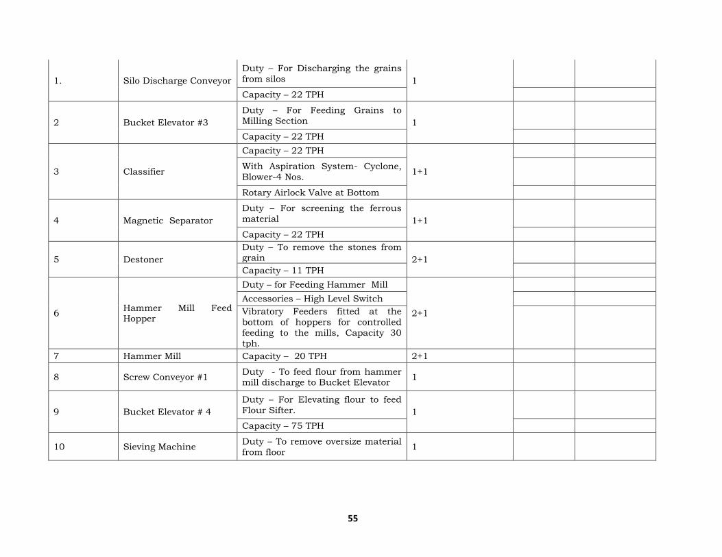
55
1. Silo Discharge Conveyor
Duty – For Discharging the grains
from silos 1
Capacity – 22 TPH
2 Bucket Elevator #3
Duty – For Feeding Grains to Milling Section 1
Capacity – 22 TPH
3 Classifier
Capacity – 22 TPH
1+1
With Aspiration System- Cyclone,
Blower-4 Nos.
Rotary Airlock Valve at Bottom
4 Magnetic Separator
Duty – For screening the ferrous
material 1+1
Capacity – 22 TPH
5 Destoner
Duty – To remove the stones from grain 2+1
Capacity – 11 TPH
6 Hammer Mill Feed Hopper
Duty – for Feeding Hammer Mill
2+1
Accessories – High Level Switch
Vibratory Feeders fitted at the
bottom of hoppers for controlled
feeding to the mills, Capacity 30 tph.
7 Hammer Mill Capacity – 20 TPH 2+1
8 Screw Conveyor #1 Duty - To feed flour from hammer mill discharge to Bucket Elevator
1
9 Bucket Elevator # 4
Duty – For Elevating flour to feed
Flour Sifter. 1
Capacity – 75 TPH
10 Sieving Machine Duty – To remove oversize material
from floor 1

56
(Oversize flour of 1.0 mm and
above shall be diverted to buffer hopper of hammer mill.)
11 Screw Conveyor #2 Duty – To feed flour from Sifter
discharge to Flour Storage Silos. 1
V Section Flour Storage, Flour Weighing Qty.
1. Flour Storage Silo
Duty – for Storing Grain Flour for 8
hours.
1
Capacity – 100 Tons of Flour,
MOC– Mild steel
with high & Low level switch
Bin activator fitted at bottom for
smooth discharge.
2. Screw Conveyor # 3
Duty - To feed flour to bucket
elevator 1
Capacity – 45 TPH
3. Bucket Elevator # 5 Duty – For Elevating Stored flour to Weighing system. Capacity – 45
TPH
1
4. Buffer Hopper Duty – To Feed flour to Weigh
Hopper. 1
5. Weigh Hopper
Capacity –25 TPH
1
Duty: To weigh Material
Duty – Weighing, MOC – SS 304
Accessories – Load cells with
Microprocessor based
programmable batch controller with built in batch counter and
totaliser.
Electro Pneumatic slide gate at
discharge.
6. Discharge Hopper with Duty – To feed Premasher Hopper
1
Screw Feeder Screw Feeder Capacity – 30 TPH

57
VI Section Common Systems For Section I
& II
1. Flour Dust Extraction
System
Duty – To avoid dusting at various
points in flour handling section
and to recycle the flour to buffer
hopper of flour weighing system.
1
2. MCC Panel for Milling Starter Panel for all Electrical
drives. 1
3
PLC Control Panel
To operate the grain milling system
in desired sequence in Auto Mode.
1
PC and PLC based Control System
SCADA is considered for Display of
Graphics
Electrical
Power Cabling from MCC to field
drive.
LOT
4
Local push button station for all
the drives
Cable trays as per layout.
5
Ducting Chutes &
Supports
All the equipments supports,
ducting / piping connection
between the equipments
LOT
Decantation Section :
Sr. Description Tech. Data M.O.C. Qty
No.
1. Thin Slop Holding Tank
after decanter Capacity : 60 M3 AISI 304 1
2. Decanter Centrifuge
AISI 304 Internals 4+1
Capacity : 15 M3
3. Thin Slops Transfer
Pump Centrifugal Type Wetted parts CF8 1+1
4. Ribbon Mixer Ribbon type AISI 304 1+1

58
5. Pipes and Fittings &
Valves
As per mentioned in respective
Annexure Lot
6. Electrical As per mentioned in respective
Annexure Lot
7. Instrumentation As per mentioned in respective
Annexure Lot
Multi-Effect Integrated Evaporator :
Integrated Evaporation Plant :
Sr. No. Equipment Description Material of
Construction Qty
1.
Falling Film Designed based on FF principle Shell: SS 304
4
Evaporator Construction: Shell & Tube Type. Tubes : SS 304 Tube
sheet: SS 304
2.
Falling Film Designed based on Forced
Circulation principle Shell: SS 304
1
Evaporator as Finisher Construction: Shell & Tube Type. Tubes : SS 304
Tube sheet: SS 304
Vapor Liquid Separators
Construction: Vertical, with
tangential entry for effective vapor
separation.
Shell : SS 304 5
Surface Condenser Shell and Tube heat exchanger Shell : SS 304 1
Thin Slop feed tank
Cylindrical / Vertical Shell with
Dished Ends SS 304 1
(Feed Tank) Cap: 50 M3
S/B/T 3/3/3
Process condensate pot
Cylindrical / Vertical Shell with
Dished Ends SS 304 1
Cap: 20 M3
S/B/T 3/3/3
Steam Condensate Pot
Horizontal MS 1
S/B/T 6/6/6

59
Feed Pump Type - Centrifugal Pump Wetted Parts : CF8 1+1
Recycle cum Transfer
pump Type - Centrifugal Pump Wetted Parts : CF8 4+ 4
Process condensate pump
Type - Centrifugal Pump Wetted Parts : CF8 1+1
Steam condensate
pump Type - Centrifugal Pump Wetted Parts : CF8 1+1
Vacuum Pump with
Motor Water Ring Type CI 1+1
CIP Tank
Cylindrical / Vertical Shell with
Dished Ends SS 304 1
Cap: 2 M3
S/B/T, 3/3/3
CIP pump Type - Centrifugal Pump Wetted Parts : CF8 1
Piping + Valves
As described in respective
annexure 1 Lot
Instrumentation
As described in respective
annexure 1 Lot
Electrical (MCC and onwards)
As described in respective annexure
1 Lot
Molasses Bulk Storage Section :
Sr.No. Description Equipment Capacity Qty. M.O.C.
1
For 120 KLD
Molasses Storage Tank 16000 MT storage capacity.
2 Mild steel, painted
Nos.
2 Raw molasses Transfer pumps. Gear type positive
displacement pumps
2+2 C.S.
Nos.
3 Interconnecting piping. Carbon steel pipes. LOT MS
4 For 200 KLD Molasses Storage Tank 16000 MT storage 2 Mild steel,

60
capacity. Nos. painted
5 Raw molasses Transfer pumps. Gear type positive displacement pumps
2+2 C.S.
Nos.
6 Interconnecting piping. Carbon steel pipes. LOT MS
Outline Technical Specifications for Molasses/Grain based 300 KLPD Ethanol plant
Storage & Handling:
Sr.No. Equipment Technical Specifications Qty. MOC
1 Raw Molasses transfer
pump
Type- Screw/Gear type Capacity-
90 MT/hr 2+1 CI
2 Day Molasses Tank Capacity- 1400 MT 1 MS
3 Molasses Transfer
Pump
Type- Screw/Gear type Capacity-
90 MT/hr 2+1 CI
4 Molasses Filter Type- Basket Strainer 1+1 MS
5 Molasses Receiving
Tank
Type - Cyl/Vert. shell with Open
Top & Conical Bottom, Capacity-
7.5 MT
1 MS
6 Molasses Weighing
System
Type- Load Cell Capacity 15 MT
Per Trip 1 MS
7 Weighed Molasses Tank
Type- Cyl/Vert. Shell with Conical
Top & Sloping Bottom, Capacity- 300 MT
1 MS
8
Weighed Molasses
Transfer Pump with
Motor
Type- Screw/Gear type Capacity-
68 MT/hr 1+1 CI
9 Molasses Diluter For
Yeast Vessel Type- Static Mixer 1 AISI304
Fermentation Section:
Sr.No. Equipment Technical Specification Qty. MOC
1 CO2 Scrubber Type: Sieve Trays Dia: 900 mm 1 AISI 304
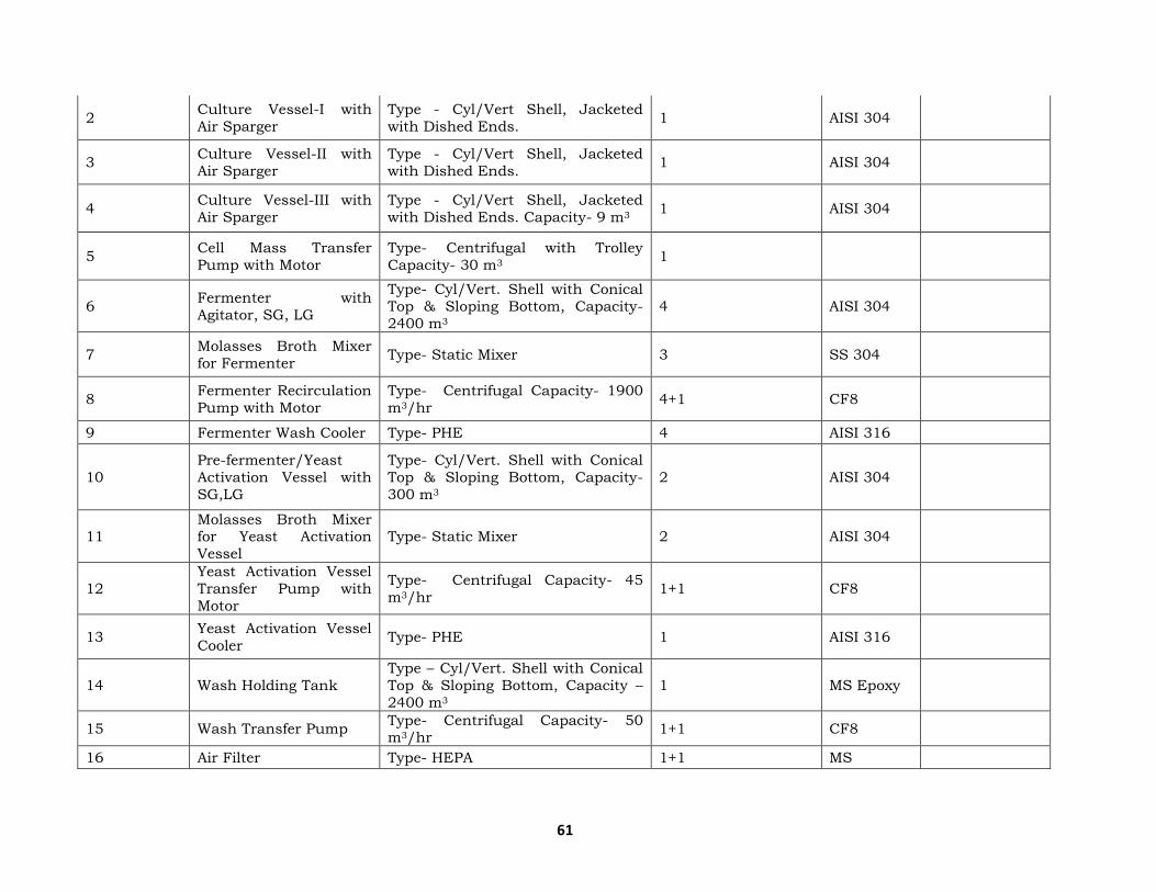
61
2 Culture Vessel-I with
Air Sparger
Type - Cyl/Vert Shell, Jacketed
with Dished Ends. 1 AISI 304
3 Culture Vessel-II with
Air Sparger
Type - Cyl/Vert Shell, Jacketed
with Dished Ends. 1 AISI 304
4 Culture Vessel-III with
Air Sparger
Type - Cyl/Vert Shell, Jacketed
with Dished Ends. Capacity- 9 m3 1 AISI 304
5 Cell Mass Transfer
Pump with Motor
Type- Centrifugal with Trolley
Capacity- 30 m3 1
6 Fermenter with
Agitator, SG, LG
Type- Cyl/Vert. Shell with Conical
Top & Sloping Bottom, Capacity-
2400 m3
4 AISI 304
7 Molasses Broth Mixer
for Fermenter Type- Static Mixer 3 SS 304
8 Fermenter Recirculation
Pump with Motor
Type- Centrifugal Capacity- 1900
m3/hr 4+1 CF8
9 Fermenter Wash Cooler Type- PHE 4 AISI 316
10
Pre-fermenter/Yeast
Activation Vessel with
SG,LG
Type- Cyl/Vert. Shell with Conical
Top & Sloping Bottom, Capacity-
300 m3
2 AISI 304
11 Molasses Broth Mixer for Yeast Activation
Vessel
Type- Static Mixer 2 AISI 304
12
Yeast Activation Vessel
Transfer Pump with
Motor
Type- Centrifugal Capacity- 45
m3/hr 1+1 CF8
13 Yeast Activation Vessel
Cooler Type- PHE 1 AISI 316
14 Wash Holding Tank
Type – Cyl/Vert. Shell with Conical
Top & Sloping Bottom, Capacity –
2400 m3
1 MS Epoxy
15 Wash Transfer Pump Type- Centrifugal Capacity- 50 m3/hr
1+1 CF8
16 Air Filter Type- HEPA 1+1 MS

62
17 Air Blower with Motor Type- Watering Capacity- 630 A
m3/hr 1+1 CI
18 Nutrient Dosing Tank
with Agitator Capacity- 7.5 m3 1 AISI 304
19 Nutrient Dosing Pump Type- Centrifugal Capacity- 7.5
m3/hr 1+1 CI
20 Acid Dosing Tank Type- Cylindrical, Vertical
Capacity- 3 m3 1 MS
21 Acid Dosing Pump Type- Centrifugal Capacity- 3
m3/hr 1+1 Alloy 20
22 Antifoam Dosing Tank Type- Cylindrical, Vertical
Capacity- 3 m3 1 MS
23 Antifoam Dosing Pump Type: Gear Capacity- 3 m3/hr 1+1 CI
24 CIP tank Type- Cylindrical, Vertical Capacity-38 m3
1+1 AISI304
25 CIP Pump Type- Centrifugal Capacity- 30
m3/hr 1+1 Alloy 20
26 Piping, Valves
Instrumentation As Per Standards Lot
Re boilers
1 Analyzer Column
Reboiler Shell & Tube Type AISI 304 2+1
2 ED Column Reboiler Shell & Tube Type AISI 304 1
3 Rectifier Cum Exhaust
Column Reboiler Shell & Tube Type AISI 304 1
4 Pre Rectifier Column
Reboiler Shell & Tube Type AISI 304 1
Condensers & Coolers
5 DG Condenser I Shell & Tube Type AISI 304 1
6 DG Condenser II Shell & Tube Type AISI 304 1
7 Analyser Condenser I &
II Shell & Tube Type AISI 304 2

63
8 ED Condenser I & II Shell & Tube Type AISI 304 2
9 Recovery Condenser Shell & Tube Type AISI 304 1
10 Vent Condenser for Analyzer
Shell & Tube Type AISI 304 2
11 PCV Condenser Shell & Tube Type AISI 304 2
12 Product Alcohol Cooler Shell & Tube Type DOW Cu 1
13 Product (RS) Cooler Shell & Tube Type AISI 304 1
14 TA Cooler Shell & Tube Type AISI 304 1
15 FO Cooler Shell & Tube Type AISI 304 4
16 R/E Alcohol Cooler Shell & Tube Type AISI 304 1
17 ED Feed Cooler Shell & Tube Type AISI 304 1
PHE's, Pumps
18 DM Water Preheater PHE, SS 316 Plates /MS Frame SS 1
19 Rectifier Feed Preheater PHE, SS 316 Plates /MS Frame SS 1
20 PR Feed Preheater PHE, SS 316 Plates /MS Frame SS 1
21 Analyser Bottom Transfer Pump
Centrifugal Type, CF8 (Wetted Parts Only)
CF8 1+1
22 Rectifier Lees Pump Centrifugal Type, CF8 (Wetted
Parts Only) CF8 1+1
23 PR Lees Pump Centrifugal Type, CF8 (Wetted
Parts Only) CF8 1+1
24 Pre Rectifier Feed Pump Centrifugal Type, CF8 (Wetted
Parts Only) CF8 1+1
25 PR Refux Pump Centrifugal Type, CF8 (Wetted
Parts Only) CF8 1+1
26 Rectifier Reflux Pump Centrifugal Type, CF8 (Wetted
Parts Only) CF8 1+1
27 FO Washing Pump Centrifugal Type, CF8 (Wetted Parts Only)
CF8 1+1

64
28 ED Bottom Transfer
Pump
Centrifugal Type, CF8 (Wetted
Parts Only) CF8 1+1
29 Alcohol Transfer Pump Centrifugal Type, CF8 (Wetted
Parts Only) CF8 1+1
30 Recovery Feed Pump Centrifugal Type, CF8 (Wetted Parts Only)
CF8 1+1
31 Steam Condensate Pump
Centrifugal Type CI 1+1
32 Vacuum Pump Water Ring Type CI 1+1
33 Emergency Water
Supply Set Standard 1
Others :
Sr.No. Description Tech. Specs. Qty.
1 FO Decanters As Per Standard 2
2 Mixing Bottle (For
ED/Purifier Column) As Per Standard 1
3 Vapour Bottles As Per Standard Lot
4 Manometer Bottles As Per Standard 2
5 Seal Pot As Per Standard 1
6 Pump capacity 6 cu.m
For Recovery Column As Per Standard 1+1
7 TA Mixing Bottle As Per Standard 1
8 Pipes & Fittings, Valves
and Instrument As Per Standard Lot
SN Description Technical Specifications Qty. MOC
1 Absorber Bed AS per standard (Suitable) 2 AISI 304
2 Evaporator Column AS per standard (Suitable) 1 AISI 304
3 Evaporator Column Re
boiler AS per standard (Suitable) 1 AISI 304
4 Feed Preheater AS per standard (Suitable) 1 AISI 304
5 Regeneration Preheater AS per standard (Suitable) 1 AISI 304
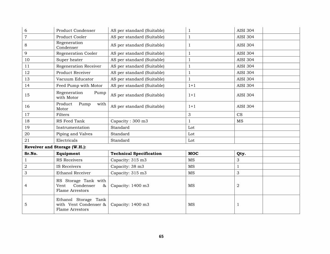
65
6 Product Condenser AS per standard (Suitable) 1 AISI 304
7 Product Cooler AS per standard (Suitable) 1 AISI 304
8 Regeneration
Condenser AS per standard (Suitable) 1 AISI 304
9 Regeneration Cooler AS per standard (Suitable) 1 AISI 304
10 Super heater AS per standard (Suitable) 1 AISI 304
11 Regeneration Receiver AS per standard (Suitable) 1 AISI 304
12 Product Receiver AS per standard (Suitable) 1 AISI 304
13 Vacuum Educator AS per standard (Suitable) 1 AISI 304
14 Feed Pump with Motor AS per standard (Suitable) 1+1 AISI 304
15 Regeneration Pump
with Motor AS per standard (Suitable) 1+1 AISI 304
16 Product Pump with
Motor AS per standard (Suitable) 1+1 AISI 304
17 Filters 3 CS
18 RS Feed Tank Capacity : 300 m3 1 MS
19 Instrumentation Standard Lot
20 Piping and Valves Standard Lot
21 Electricals Standard Lot
Reveiver and Storage (W.H.):
Sr.No. Equipment Technical Specification MOC Qty.
1 RS Receivers Capacity: 315 m3 MS 3
2 IS Receivers Capacity: 38 m3 MS 1
3 Ethanol Receiver Capacity: 315 m3 MS 3
4
RS Storage Tank with
Vent Condenser &
Flame Arrestors
Capacity: 1400 m3 MS 2
5
Ethanol Storage Tank
with Vent Condenser &
Flame Arrestors
Capacity: 1400 m3 MS 1
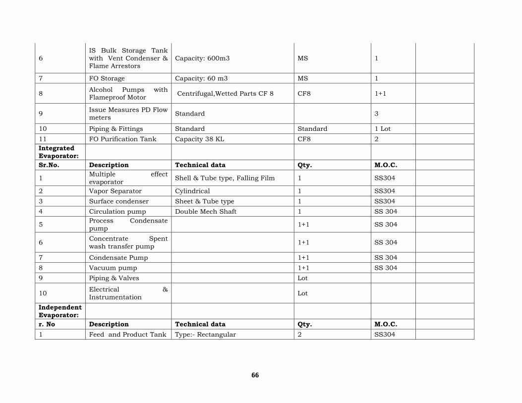
66
6
IS Bulk Storage Tank
with Vent Condenser & Flame Arrestors
Capacity: 600m3 MS 1
7 FO Storage Capacity: 60 m3 MS 1
8 Alcohol Pumps with Flameproof Motor
Centrifugal,Wetted Parts CF 8 CF8 1+1
9 Issue Measures PD Flow
meters Standard 3
10 Piping & Fittings Standard Standard 1 Lot
11 FO Purification Tank Capacity 38 KL CF8 2
Integrated
Evaporator:
Sr.No. Description Technical data Qty. M.O.C.
1 Multiple effect
evaporator Shell & Tube type, Falling Film 1 SS304
2 Vapor Separator Cylindrical 1 SS304
3 Surface condenser Sheet & Tube type 1 SS304
4 Circulation pump Double Mech Shaft 1 SS 304
5 Process Condensate
pump 1+1 SS 304
6 Concentrate Spent
wash transfer pump 1+1 SS 304
7 Condensate Pump 1+1 SS 304
8 Vacuum pump 1+1 SS 304
9 Piping & Valves Lot
10 Electrical &
Instrumentation Lot
Independent
Evaporator:
r. No Description Technical data Qty. M.O.C.
1 Feed and Product Tank Type:- Rectangular 2 SS304
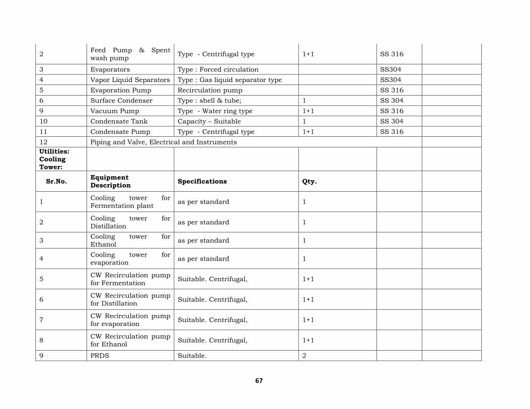
67
2 Feed Pump & Spent
wash pump Type - Centrifugal type 1+1 SS 316
3 Evaporators Type : Forced circulation SS304
4 Vapor Liquid Separators Type : Gas liquid separator type SS304
5 Evaporation Pump Recirculation pump SS 316
6 Surface Condenser Type : shell & tube; 1 SS 304
9 Vacuum Pump Type - Water ring type 1+1 SS 316
10 Condensate Tank Capacity – Suitable 1 SS 304
11 Condensate Pump Type - Centrifugal type 1+1 SS 316
12 Piping and Valve, Electrical and Instruments
Utilities: Cooling
Tower:
Sr.No. Equipment
Description Specifications Qty.
1 Cooling tower for Fermentation plant
as per standard 1
2 Cooling tower for
Distillation as per standard 1
3 Cooling tower for
Ethanol as per standard 1
4 Cooling tower for
evaporation as per standard 1
5 CW Recirculation pump
for Fermentation Suitable. Centrifugal, 1+1
6 CW Recirculation pump
for Distillation Suitable. Centrifugal, 1+1
7 CW Recirculation pump
for evaporation Suitable. Centrifugal, 1+1
8 CW Recirculation pump
for Ethanol Suitable. Centrifugal, 1+1
9 PRDS Suitable. 2

68
10 Instrument Air
compressor & dryer Suitable capacity 1+1
11 Piping, Valves standard Lot
12 Instrumentation standard Lot
13 Liqufication Cooling Tower
standard Lot
Slop Fired Incinerator Boiler & Turbine:
Sr. No. Particulars Specification Qty.
1
Slop fired incinerator
boiler with coal as supporting fuel
Capacity 75 TPH, working pressure 45 Kg/Cm2 (g)
1
2 Turbine
Capacity of 6 MW back pressure
with exhaust pressure of 4.5
Kg/Cm2(g)
1
Water Treatment Area Filtration Plant:
Sr. No. Particulars MOC Qty.
1 Multi grade Sand
Filter 1 No.
Pressure vessel
internally painted with
black bituminous and
externally with red oxide primer
MS with epoxy coating 1 No.
Piping work with valves 1 No.
Graded filtering sand
specifically selected and
graded
1 No.
2 Activated Carbon Filter
1 No.

69
Pressure vessel
internally painted with
black bituminous and externally with red
oxide primer
MS with epoxy coating 1 No.
Piping works with
valves 1 No.
3 Softener 1 No.
Pressure with rubber lining from inside and
externally with red
oxide primer
1 No.
Piping works with
valves 1 Set
Cation Exchange resign 1 Set
Hardness test kit 1 Set
Brine saturated tank of
MS construction 1 No.
Brine distribution
system 1 Lot
4 D.M. PLANT ( 1 No.) 1 No.
1 Strong acid cation 1 No.
2 Degasser tower & pump 1 No.
3 Strong acid anion 1 No.
4 Mixed bed exchanger 1 No.
grain receipt & cleaning, milling & flour handling section:
I Section Grain Receipt / Cleaning Section Qty.
1. Receiving Hopper
Duty – To feed Grains to Chain Conveyor
1
Bags to be dumped manually in the hopper.
Safety Grill on the top

70
Manual Slide Gate at Bottom.
Provided with hood on top for
dedusting.
2. Bucket Elevator #1
Duty – For feeding grains to Pre-
Cleaner 1
Capacity – 68 TPH
3. Bag Dump Station
Fitted on the receiving hopper to
avoid dusting in receiving area.
Filter bags and pulse valve for cleaning
1
M.O.C. – M. S.
4. Chain Conveyer
Duty – For feeding grains to Pre-Cleaner 1
Capacity – 68 TPH
5. Drum Cleaner
Duty – For screening the impurities. 1
Capacity – 68 TPH
6. Bucket Elevator #2
Duty – For Feeding Grains to
Storage Silos 1
Capacity – 68 TPH MOC-Mild
steel,
II Section Grain Storage Section Qty.
1. Bulk Storage GIC Silos
Galvanised Flat Bottom Silos
2+1
Capacity – 7500 MT with Level Sensors, Aeration System, Sweep
Auger. Discharge Gates
III Section Common Systems For Section I
& III
1.
Electrical Starter Panel for all Electrical
drives With Necessary interlocks, Mimic, and control push button
station.
1
MCC Panel
2. Electrical Power cabling from MCC to field
drive.

71
Local push button station for all
the drives.
3. Ducting Chutes &
Supports
All the equipments supports,
ducting / piping connection
between the equipments
LOT
IV Section Mill Feed, Milling, Flour Sieving Qty.
1. Silo Discharge Conveyor
Duty – For Discharging the grains
from silos 1
Capacity – 33 TPH
2 Bucket Elevator #3
Duty – For Feeding Grains to
Milling Section 1
Capacity – 33 TPH
3 Classifier
Capacity – 33 TPH
1+1
With Aspiration System- Cyclone, Blower-4 Nos.
Rotary Airlock Valve at Bottom
4 Magnetic Separator
Duty – For screening the ferrous
material 1+1
Capacity – 33 TPH
5 Destoner
Duty – To remove the stones from
grain 2+1
Capacity – 17 TPH
6 Hammer Mill Feed
Hopper
Duty – for Feeding Hammer Mill
2+1
Accessories – High Level Switch
Vibratory Feeders fitted at the
bottom of hoppers for controlled
feeding to the mills, Capacity 45
tph.
7 Hammer Mill Capacity – 30 TPH 2+1
8 Screw Conveyor #1 Duty - To feed flour from hammer
mill discharge to Bucket Elevator 1
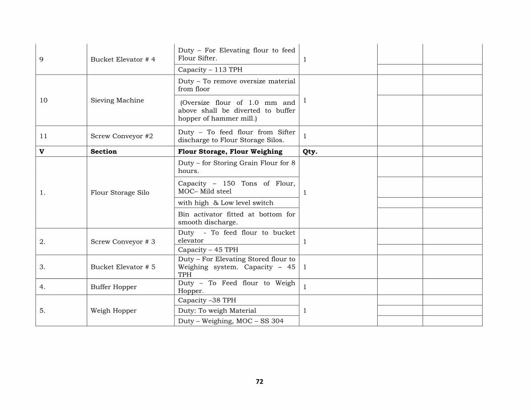
72
9 Bucket Elevator # 4
Duty – For Elevating flour to feed
Flour Sifter. 1
Capacity – 113 TPH
10 Sieving Machine
Duty – To remove oversize material from floor
1
(Oversize flour of 1.0 mm and
above shall be diverted to buffer
hopper of hammer mill.)
11 Screw Conveyor #2 Duty – To feed flour from Sifter
discharge to Flour Storage Silos. 1
V Section Flour Storage, Flour Weighing Qty.
1. Flour Storage Silo
Duty – for Storing Grain Flour for 8
hours.
1
Capacity – 150 Tons of Flour,
MOC– Mild steel
with high & Low level switch
Bin activator fitted at bottom for
smooth discharge.
2. Screw Conveyor # 3
Duty - To feed flour to bucket
elevator 1
Capacity – 45 TPH
3. Bucket Elevator # 5
Duty – For Elevating Stored flour to
Weighing system. Capacity – 45 TPH
1
4. Buffer Hopper Duty – To Feed flour to Weigh
Hopper. 1
5. Weigh Hopper
Capacity –38 TPH
1
Duty: To weigh Material
Duty – Weighing, MOC – SS 304
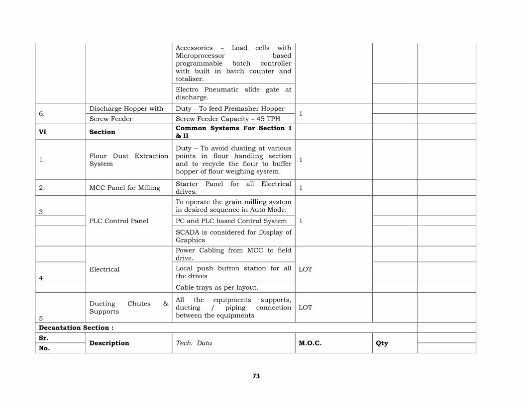
73
Accessories – Load cells with Microprocessor based
programmable batch controller
with built in batch counter and
totaliser.
Electro Pneumatic slide gate at
discharge.
6. Discharge Hopper with Duty – To feed Premasher Hopper
1
Screw Feeder Screw Feeder Capacity – 45 TPH
VI Section Common Systems For Section I
& II
1. Flour Dust Extraction
System
Duty – To avoid dusting at various
points in flour handling section
and to recycle the flour to buffer hopper of flour weighing system.
1
2. MCC Panel for Milling Starter Panel for all Electrical
drives. 1
3
PLC Control Panel
To operate the grain milling system
in desired sequence in Auto Mode.
1
PC and PLC based Control System
SCADA is considered for Display of
Graphics
Electrical
Power Cabling from MCC to field
drive.
LOT
4
Local push button station for all
the drives
Cable trays as per layout.
5
Ducting Chutes &
Supports
All the equipments supports,
ducting / piping connection
between the equipments
LOT
Decantation Section :
Sr. Description Tech. Data M.O.C. Qty
No.

74
1. Thin Slop Holding Tank
after decanter Capacity : 90 M3 AISI 304 1
2. Decanter Centrifuge
AISI 304 Internals 4+1
Capacity : 22.5 M3
3. Thin Slops Transfer
Pump Centrifugal Type Wetted parts CF8 1+1
4. Ribbon Mixer Ribbon type AISI 304 1+1
5. Pipes and Fittings & Valves
As per mentioned in respective Annexure
Lot
6. Electrical As per mentioned in respective Annexure
Lot
7. Instrumentation As per mentioned in respective
Annexure Lot
Multi-Effect Integrated Evaporator :
Integrated Evaporation Plant :
Sr. No. Equipment Description Material of
Construction Qty
1.
Falling Film Designed based on FF principle Shell: SS 304
4
Evaporator Construction: Shell & Tube Type. Tubes : SS 304 Tube
sheet: SS 304
2.
Falling Film Designed based on Forced
Circulation principle Shell: SS 304
1
Evaporator as Finisher Construction: Shell & Tube Type. Tubes : SS 304
Tube sheet: SS 304
Vapor Liquid Separators Construction: Vertical, with tangential entry for effective vapor
separation.
Shell : SS 304 5
Surface Condenser Shell and Tube heat exchanger Shell : SS 304 1
Thin Slop feed tank
Cylindrical / Vertical Shell with Dished Ends
SS 304 1

75
(Feed Tank) Cap: 75 M3
S/B/T 3/3/3
Process condensate pot
Cylindrical / Vertical Shell with
Dished Ends SS 304 1
Cap: 30 M3
S/B/T 3/3/3
Steam Condensate Pot
Horizontal MS 1
S/B/T 6/6/6
Feed Pump Type - Centrifugal Pump Wetted Parts : CF8 1+1
Recycle cum Transfer
pump Type - Centrifugal Pump Wetted Parts : CF8 4+ 4
Process condensate
pump Type - Centrifugal Pump Wetted Parts : CF8 1+1
Steam condensate pump
Type - Centrifugal Pump Wetted Parts : CF8 1+1
Vacuum Pump with Motor
Water Ring Type CI 1+1
CIP Tank
Cylindrical / Vertical Shell with Dished Ends
SS 304 1
Cap: 3 M3
S/B/T, 3/3/3
CIP pump Type - Centrifugal Pump Wetted Parts : CF8 1
Piping + Valves
As described in respective
annexure 1 Lot
Instrumentation
As described in respective annexure
1 Lot
Electrical (MCC and
onwards)
As described in respective
annexure 1 Lot
Molasses Bulk Storage Section :
Sr.No. Description Equipment Capacity Qty. M.O.C.
1 For 300 KLD Molasses Storage Tank 36000 MT storage
capacity.
3 Mild steel,
painted Nos.
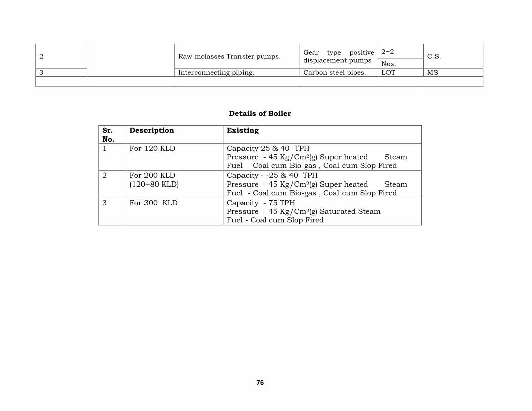
76
2 Raw molasses Transfer pumps. Gear type positive
displacement pumps
2+2 C.S.
Nos.
3 Interconnecting piping. Carbon steel pipes. LOT MS
Details of Boiler
Sr. No.
Description Existing
1 For 120 KLD Capacity 25 & 40 TPH Pressure - 45 Kg/Cm2(g) Super heated Steam Fuel - Coal cum Bio-gas , Coal cum Slop Fired
2 For 200 KLD (120+80 KLD)
Capacity - -25 & 40 TPH Pressure - 45 Kg/Cm2(g) Super heated Steam Fuel - Coal cum Bio-gas , Coal cum Slop Fired
3 For 300 KLD Capacity - 75 TPH Pressure - 45 Kg/Cm2(g) Saturated Steam Fuel - Coal cum Slop Fired

77
Details Of Existing And Proposed Stack
Capacity
of Boiler
Stack
Height
Flue gas
temp. 0C
Pollution
Control
Equipment
TPM
(mg/Nm3)
SOx
(mg/Nm3)
NOx
(mg/Nm3)
For 120 KLD Plant
40 TPH
25 TPH
82 MTR 160 ° C Air
Preheater,
Dust Collector,
Electrostatic
Precipitator,
50 (max) 80 μg/m3 80 μg/m3
For 200 ( 120 +80 ) KLD Plant
65 TPH 82 MTR 160–
170°C
Air
Preheater,
Dust
Collector,
Electrostatic Precipitator,
Bag Filters
50 (max) 80 μg/m3 80 μg/m3
For 300 KLD Plant
75 TPH 82 MTR 160–
180°C
Air
Preheater,
Dust Collector,
Electrostatic
Precipitator,
Bag Filters
50 (max) 80 μg/m3 80 μg/m3
ii Residential area (Non Processing area)
As the local people from nearby villages shall be engaged in project activity.
Therefore no housing / building is proposed.
iii Greenbelt
Approx 30 acres area ( inside and out side of the site ) has been covered with
the good green belt in with 40000 number of tress. Further it is proposed to
cover 45 acres in next 05 years of time.
iv Social Infrastructure
Company shall evaluate the need base program under CSR and shall execute as
per the given plan.
v Connectivity
Site is well connected with by State Highway Bhopal- Raisen- Sanchi Vidisha
road .

78
vi Drinking water management
Drinking water will be supplied through bore well with proper RO system.
vii Sewerage System
The domestic waste shall be taken to soak pit and septic tank.
viii Industrial waste management
As described earlier.
ix Solid waste management
As described earlier.
x Power Requirement and supply / source
As described earlier.
7.0 Rehabilitation & Resettlement Plan
No R & R plan is required.
8.0 Project Schedule and Cost estimate
i. Likely date of start of construction and likely date of completion
After obtaining environmental clearance and water / air consent the company
shall start the project. Proposed date shall be July 2019 (subject to clearances)
ii. Estimated project cost along with analysis in terms of economic viability
of the project
Estimated Investment for Design, Engineering, Manufacture, Supply, Erection
and Supervision of commissioning for proposed Plant as per the sections
mentioned below are as follows:
Project Cost of Proposed Unit
Description Particulars Distillery Plant (Rs. Lakh)
For Existing 120 KLD Plant Land and Site Development 4.52 Cr
Buildings 27.39 Cr
Indigenous Plant and Machinery
200 Cr
Miscellaneous Fixed Assets 7.42 Cr
Prelim. & Preoperative Expenses
Contingencies
Working capital margin
Total 239.88 Cr
Out of Above, The capital cost for Slope Fired boiler, MEE, CPU, Rain water harvesting is around - 4000Lacs.
For Existing 120+80 KLD Plant Land and Site Development -
Buildings -
Indigenous Plant and Machinery
3.15 Cr

79
Miscellaneous Fixed Assets -
Prelim. & Preoperative Expenses
-
Contingencies -
Working capital margin -
Total 239.88 + 3.15 Cr
Out of Above, The capital cost for Slope Fired boiler, MEE, CPU, Rain water harvesting is around - 4500Lacs.
For 300 KLD Plant
Land and Site Development 20 Cr
Buildings 35 Cr
Indigenous Plant and Machinery
500 Cr
Miscellaneous Fixed Assets 100 Cr
Prelim. & Preoperative Expenses
-
Contingencies 100
Working capital margin 100
Total 855 Cr
Out of Above, The capital cost for Slope Fired boiler, MEE, CPU, Rain water harvesting is around 6000 Lacs.
Total Project cost of 500 KLD plant will be 1098 Crore and out of that Rs 60 Crore will be incurred on Pollution control aspect as capital cost.
9.0 Analysis of Proposal (Final Recommendation)
Financial and social benefits with special emphasis on the benefit to the
local people including tribal population, if any, in the area.
From the foregoing analysis, it is observed that proposal is environmental
compatible and will helps to people improving their financial status,
performance and repayment capability. This also helps the company in
venturing into production of niche specialty products which will eventually
better their profits and also their ranking in the industry. CSR programme shall
be executed through the group discussion and need base programme will be
proposed for the area, by which people of the area will be benefitted.