Prague, 8-11 June 2009 - Smart grid€¢ Study new approaches to distribution ... Prague, 8-11 June...
20
Prague, 8-11 June 2009 Open Source Software for Open Source Software for Simulating Active Distribution Systems Roger C. Dugan Sr. Technical Executive EPRI, USA Prague, 8-11 June 2009 OpenDSS EPRI h l d it Di t ib ti S t • EPRI has released its Distribution System Simulator (DSS) program as open source • Called “OpenDSS” • Can be found at: WWW SOURCEFORGE NET – WWW.SOURCEFORGE.NET – (Search for OpenDSS)
Transcript of Prague, 8-11 June 2009 - Smart grid€¢ Study new approaches to distribution ... Prague, 8-11 June...

Prague, 8-11 June 2009
Open Source Software forOpen Source Software for Simulating Active Distribution
SystemsRoger C. Dugan
Sr. Technical ExecutiveEPRI, USA
Prague, 8-11 June 2009
OpenDSS
EPRI h l d it Di t ib ti S t• EPRI has released its Distribution System Simulator (DSS) program as open source
• Called “OpenDSS”• Can be found at:
WWW SOURCEFORGE NET– WWW.SOURCEFORGE.NET– (Search for OpenDSS)

Prague, 8-11 June 2009
Why was DSS Developed?
DSS d l d t id• DSS was developed to provide a very flexible research platform and a foundation for special distribution analysis applications such as DG analysis
• Fills gaps left by other distribution system g p y yanalysis tools.
• Study new approaches to distribution system analysis.
Prague, 8-11 June 2009
Why OpenDSS?
EPRI h d th DSS t• EPRI has made the DSS open source to:– Cooperate with other open source efforts in the
USA in Smart Grid research– To encourage new advancements in distribution
system analysis– To provide Smart Grid researchers a tool for
testing algorithms

Prague, 8-11 June 2009
Current Related EPRI Activities
• Intelligrid– Distribution Fast Simulation & Modeling– DSE – Distribution State Estimator
• CIM/DCIM• OpenDSS – Distribution System SimulatorOpenDSS Distribution System Simulator
– Multipurpose distribution system analysis tool– Open source version released – 5 Sept 2008– Official release – November 2008
Prague, 8-11 June 2009
DSS Background• Under development for more than 10 Years
St t d t El t t k C t i 1997– Started at Electrotek Concepts in 1997 – Purchased by EPRI in 2004
• Objectives in 1997– Tool to support all distribution planning aspects of
distributed generation– Implement a flexible research platformImplement a flexible research platform– Incorporate object-oriented data ideas
• Key Future work– Platform for DSE for North American Systems– Research platform for reliability tools

Prague, 8-11 June 2009
Distribution System Simulator (DSS)
The DSS is designed to sim late tilit distrib tionThe DSS is designed to simulate utility distribution systems in arbitrary detail for most types of analyses related to distribution planning.– It performs its analysis types in the frequency domain,
• Power flow, • Harmonics, and • Dynamics.
– It does NOT perform electromagnetic transients (time domain) studies.
Prague, 8-11 June 2009
Overall Model Concept
Inf. Bus(Voltage, Angle)
Power DeliverySystem
ControlCenter
Control
Power ConversionElement
("Black Box")
CommMsg Queue 1
CommMsg Queue 2
Prague, 8-11 June 2009
Example DSS Applications• Neutral-to-earth (stray) voltage • Distribution automation controlNeutral to earth (stray) voltage
simulations. • Loss evaluations due to unbalanced
loading.• Development of DG models for the
IEEE Radial Test Feeders.• High-frequency harmonic and
interharmonic interference.
Distribution automation control algorithm assessment.
• Impact of tankless water heaters on flicker and distribution transformers.
• Wind farm collector simulation.• Wind farm impact on local
transmission.• Losses, impedance, and circulating
currents in unusual transformer bank configurations.
• Transformer frequency response analysis.
• Wind generation and other DG impact on switched capacitors and voltage regulators.
• Open-conductor fault conditions with a variety of single-phase and three-phase transformer connections.
Prague, 8-11 June 2009
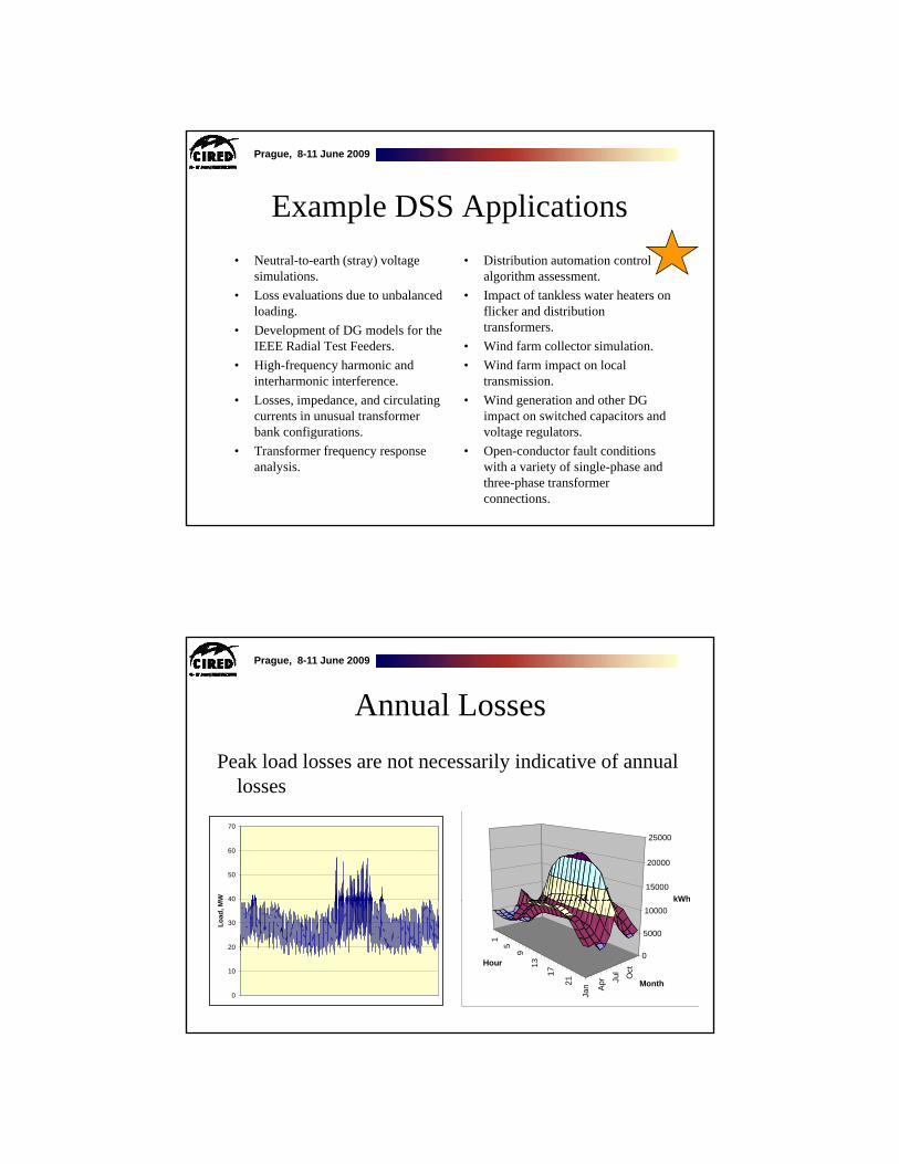
Annual LossesPeak load losses are not necessarily indicative of annual y
losses
40
50
60
70
W
15000
20000
25000
kWh
0
10
20
30
40
Load
, M
15
9
13
17
21
Jan Apr Ju
l Oct
0
5000
10000kWh
Hour
Month

Prague, 8-11 June 2009
Solar PV Simulation5 5
Without PV With PV
2
3
4M
W 2
3
4
Diff
eren
ce, M
W
Difference
-1
0
1
2 Weeks-1
0
1
Prague, 8-11 June 2009
Power Distribution Efficiency
0
50
100
150
200
250
300
350
0 50 100 150
Hour (1 Week)
Loss
es, k
W
Total Losses
Load Losses
No-Load Losses
250
300
350
kW
Total Losses
Peak Load Week
Hour (1 Week)
0
50
100
150
200
5200 5250 5300 5350
Hour (1 Week)
Loss
es, k
Load Losses
No-Load Losses
Light Load Week

Prague, 8-11 June 2009
Wind Plant 1-s Simulation4000
Active and Reactive Power
0.99
1.00
1.01
1.02
1.03Feeder Voltage and Regulator Tap Changes
0
1000
2000
3000
91
-491
-391
-291
-191
-91
P3-
(kW
) (W
)Q
3-(k
var)
(V
Ar)
0.97
0.98
0.96
0.98
1.00
1.02
0 20000 40000 60000 80000
Electrotek Concepts® TOP, The Output Processor®
Ta
p-(
pu
) (
V)
Time (s)
-5910 20000 40000 60000 80000
Electrotek Concepts® TOP, The Output Processor®Time (s)
Prague, 8-11 June 2009
Architecture

Prague, 8-11 June 2009
DSS StructureScripts
Main Simulation EngineCOM Interface
Scripts,
User-Written DLLsp
Results
Prague, 8-11 June 2009
DSS Object StructureDSS Executive
Commands Options
Circuit
PDElement PCElement Controls Meters General
Solution
V [Y] I
LineTransformerCapacitorReactor
LoadGeneratorVsourceIsource
RegControlCapControlRelayRecloseFuse
MonitorEnergyMeterSensor
LineCodeLineGeometryWireDataLoadShapeGrowthShapeSpectrumTCCcurve

Prague, 8-11 June 2009
Power Delivery Elements Power Delivery
Element
Iterm = [Yprim] Vterm
Terminal 2Terminal 1
Prague, 8-11 June 2009
Power Conversion ElementsITerm(t) = F(VTerm, [State], t)
VF∂∂
Power ConversionElement
V∂

Prague, 8-11 June 2009
Load (a PC Element)
YprimCompensation CurrentYprimCompensation Current
(One-Line Diagram)
Prague, 8-11 June 2009
Putting it All TogetherYprim 1 Yprim 2 Yprim 3 Yprim n
ALL Elements
Yprim 1 Yprim 2 Yprim 3 Yprim n
Y=IinjI2
I1
PC Elements
V Node
Im
Voltages
Iteration Loop

Prague, 8-11 June 2009
Scripting Basics
Prague, 8-11 June 2009
A Basic ScriptLINE1
TR1
Sourcebus Sub_busLoadbus
LOAD1
Source
115 kV12.47 kV
1000 kW0.95 PF
1 Mile, 336 ACSR
New Circuit.Simple ! Creates voltage source (Vsource.Source)
Edit Vsource.Source BasekV=115 pu=1.05 ISC3=3000 ISC1=2500 !Define source V and Z
New Transformer.TR1 Buses=[SourceBus, Sub_Bus] Conns=[Delta Wye] kVs= [115 12.47]
~ kVAs=[20000 20000] XHL=10
New Linecode.336ACSR R1=0.058 X1=.1206 R0=.1784 X0=.4047 C1=3.4 C0=1.6 Units=kft
New Line.LINE1 Bus1=Sub_Bus Bus2=LoadBus Linecode=336ACSR Length=1 Units=Mi
New Load.LOAD1 Bus1=LoadBus kV=12.47 kW=1000 PF=.95
Solve
Show Voltages
Show Currents
Show Powers kVA elements

Prague, 8-11 June 2009
Solution Modes
Prague, 8-11 June 2009
Distribution System Analysis Tools
• DSS has the basic tools for Planning built in:• DSS has the basic tools for Planning built in:– Power Flow– Short Circuit Calculations
• In Addition, it has Several Advanced Capabilities– “Dynamic” Power Flow– Other power flow modes
Dynamics– Dynamics– Harmonics
• If it is not built in, you can drive it from another program such as Matlab– For example: Reliability Analysis

Prague, 8-11 June 2009
Classes of Solution Modes• Power Flow • Other Power Flow• Power Flow
– Snapshot– Direct
• Dynamic Power Flow– Daily– Yearly
DutyCycle
• Other Power Flow– LD1– LD2– Monte Carlo
• M1• M2• M3
– DutyCycle– Peakday
• Dynamics• Harmonics
• Short Circuit– Faultstudy– MF - Monte Carlo Fault
Prague, 8-11 June 2009
Introduction to Driving the COM Server from another Application

Prague, 8-11 June 2009
Active objects concept• There is one registered In Process COM interface:• There is one registered In-Process COM interface:
– OpenDSSEngine.DSS• That is, the DSS interface is the one you instantiate• The DSS interface creates all the others.
• The interfaces generally employ the idea of an ACTIVE object– Active circuitActive circuit, – Active circuit element, – Active bus, etc.– The interfaces generally point to the active object
• To work with another object, change the active object.
Prague, 8-11 June 2009
DSS InterfaceThis interface is instantiated upon loading O DSSE i DSS d thOpenDSSEngine.DSS and then instantiates all other interfaces
Call the Start(0) method to initialize the DSS
DSS Class Functions (methods) and Properties

Prague, 8-11 June 2009
Instantiate the DSS Interface and Attempt Start
Public Sub StartDSS()
' Create a new instance of the DSS
Set DSSobj = New OpenDSSengine.DSS
' Start the DSS
If Not DSSobj.Start(0) Then
MsgBox "DSS Failed to Start"
Else
MsgBox "DSS Started successfully“
' Assign a variable to the Text interface for easier access
Set DSSText = DSSobj.Text
End If
End Sub
Prague, 8-11 June 2009
Accessing the COM Server
In MATLAB:• In MATLAB:– DSSobj = actxserver(‘OpenDSSEngine.DSS’);
• In VBA:– Public DSSobj As OpenDSSEngine.DSS
Set DSSobj = New OpenDSSEngine.DSS
• In PYTHON:– self.engine =
win32com.client.Dispatch("OpenDSSEngine.DSS")

Prague, 8-11 June 2009
TEXT Interface
Text interface is simplest
Interfaces as Exposed by VBA Object Browser in MS Excel
Text has two Properties
Prague, 8-11 June 2009
Assign a Variable to the Text Interface
Public Sub StartDSS()
' Create a new instance of the DSS
Set DSSobj = New OpenDSSengine.DSS
' Start the DSS
If Not DSSobj.Start(0) Then
MsgBox "DSS Failed to Start"
Else
MsgBox "DSS Started successfully“
' Assign a variable to the Text interface for easier access
Set DSSText = DSSobj.Text
End If
End Sub

Prague, 8-11 June 2009
Now Use the Text Interface …• You can issue any of the DSS script commands from the
Text interface
‘ Always a good idea to clear the DSS when loading a new circuit
DSSText.Command = "clear"
' Compile the script in the file listed under "fname" cell on the main form
DSSText.Command = "compile " + fname
‘ Set regulator tap change limits for IEEE 123 bus test case
With DSSText
.Command = "RegControl.creg1a.maxtapchange=1 Delay=15 !Allow only one tap change per solution. This one moves first"This one moves first
.Command = "RegControl.creg2a.maxtapchange=1 Delay=30 !Allow only one tap change per solution"
.Command = "RegControl.creg3a.maxtapchange=1 Delay=30 !Allow only one tap change per solution"
.Command = "RegControl.creg4a.maxtapchange=1 Delay=30 !Allow only one tap change per solution"
.Command = "RegControl.creg3c.maxtapchange=1 Delay=30 !Allow only one tap change per solution"
.Command = "RegControl.creg4b.maxtapchange=1 Delay=30 !Allow only one tap change per solution"
.Command = "RegControl.creg4c.maxtapchange=1 Delay=30 !Allow only one tap change per solution"
.Command = "Set MaxControlIter=30"
End With
Prague, 8-11 June 2009
Result Property
• The Result property is a Read Only property• The Result property is a Read Only property that contains any result messages the most recent command may have issued.– Error messages– Requested values
‘ Example: Query line length
DSSText.Command = “? Line.L1.Length”
S = DSSText.Result ‘ Get the answer
MsgBox S ‘ Display the answer

Prague, 8-11 June 2009
User-Written Controls
From the COM Interface
Prague, 8-11 June 2009
Basic Control Loop Flow ChartIf you set Number=1,
o can break in
You can single-step through this
Initialize Loop
Solve Circuit
Check ControlsNext Time Step
you can break in here
Control Actions Done?NO YES

Prague, 8-11 June 2009
Control Loop (Actual Pascal Code)FUNCTION TSolutionObj.SolveSnap:Integer; // solve for now onceVAR
TotalIterations :Integer;TotalIterations :Integer;Begin
SnapShotInit;TotalIterations := 0;REPEAT
Inc(ControlIteration);Result := SolveCircuit; // Do circuit solution w/o checking controls{Now Check controls}CheckControls;{For reporting max iterations per control iteration}If Iteration > MostIterationsDone THEN MostIterationsDone := Iteration;TotalIterations := TotalIterations + Iteration;
UNTIL ControlActionsDone or (ControlIteration >= MaxControlIterations);If Not ControlActionsDone and (ControlIteration >= MaxControlIterations) then Begin
DoSimpleMsg('Warning Max Control Iterations Exceeded. ' + CRLF + 'Tip: Show Eventlog to debug control settings.', 485);
SolutionAbort := TRUE; // this will stop this message in dynamic power flow modesEnd;If ActiveCircuit.LogEvents Then LogThisEvent('Solution Done');Iteration := TotalIterations; { so that it reports a more interesting number }
End;
Prague, 8-11 June 2009
External Script and COM Interface Options
• Take Immediate action or keep track of time• Take Immediate action or keep track of time yourself– Set Number=1 – Sample after solution step– Execute command to change element state
• Use the DSS Control Queue through COM Proxy– Set Number=1Set Number 1– Step through solution– Push control commands onto DSS control queue
• (Allows DSS to keep track of when control actions happen)– Write routines to handle pending actions

Prague, 8-11 June 2009
Control Proxy in COM InterfaceCOM Interface Control Proxy Operation
COM Interface
CONTROL OBJECT
ACTION 1
ACTION 2
CONTROL
DISPATCHER
DoPendingAction
POP
COM CONTROL Proxy
DoPendingAction
Action ListUSER CODE POP
PUSH
ALL PUSHES ARE SORTED
DSS Control Queue
ACTION 3
...
ACTION N
CONTROL OBJECT
DoPendingAction
TimeAction CodeProxy HandleControl Addr
BY TIME
Prague, 8-11 June 2009
For More Information
See Wiki
Download “Training” from SOURCEFORGE site