Practical work 6
26
EC202- Computer Aided Design PRACTICAL EVALUATION FORM NAME:………………………………………………………. CLASS.: ……………… REGISTRATION NO.: ……………………………………… PRACTICAL WORK: 6 APPLICATION OF AUTOCAD PACKAGE IN TECHNICAL AND ELECTRICAL DRAWINGS: LAYERS, BLOCK, INSERT COMMANDS & GENERATE DERAWING OUTPUTS. No . Skill i. Accuracy ii. Within time frame Excellent (8-10 marks) Average (5-7 Marks) Weak (0-4 Marks) Total 1. Layers created 2. Symbols created 3. Make Block command 4. Insert Block command 5. Print Command Sub-Total /50 No . Report Total amy/khk/jke/puo EC6.1
-
Upload
wkhairil80 -
Category
Education
-
view
86 -
download
0
Transcript of Practical work 6

EC202- Computer Aided Design
PRACTICAL EVALUATION FORM
NAME:………………………………………………………. CLASS.: ………………
REGISTRATION NO.: ………………………………………
PRACTICAL WORK: 6
APPLICATION OF AUTOCAD PACKAGE IN TECHNICAL AND ELECTRICAL
DRAWINGS: LAYERS, BLOCK, INSERT COMMANDS & GENERATE DERAWING
OUTPUTS.
No.
Skill
i. Accuracy
ii. Within time frame
Excellent
(8-10 marks)
Average
(5-7 Marks)
Weak
(0-4 Marks)Total
1. Layers created
2. Symbols created
3. Make Block command
4. Insert Block command
5. Print Command
Sub-Total /50
No. Report Total
1. Discussion /4
2. Question /4
3. Reflection /2
Sub-Total /10
Total /60
amy/khk/jke/puo EC6.1

EC202- Computer Aided Design
PRACTICAL WORK: 6
TITLE : APPLICATION OF AUTOCAD PACKAGE IN TECHNICAL AND
ELECTRICAL DRAWINGS
COURSE LEARNING OUTCOME:
CLO 4: Apply the draw and edit commands skillfully to produce simple and
complex technical drawings.
CLO 5: Produce with precision the drawings of graphics, electronic circuits
schematics and electrical wiring layout diagrams faster and neat.
OBJECTIVES: The students should be able to:
1. Create layers and set color and linetype for complicated drawings.
2. Create block by using the block command to transform a group of objects
into one object.
3. Create WBlock for insertion of .DWG files into other drawings/Insert and
Minsert objects to bring blocks into drawings.
4. Set Printing area, paper size, paper orientation and drawing scale by using
the Print Command.
THEORY :
The concept of layers is very important in AutoCAD and the correct use of layers can make
your drawing much easier to work with. Basically, layers are the computer equivalent of
tracing overlays on a drawing board. However, layers are much more powerful because you
can have many layers in a single drawing and you can control the visibility, colour and
linetype of layers independently. This makes working with very complicated drawings much
more efficient.
Block Command in Autocad is a collection of all of the line and arc entities that create an
object, 'moulded' together to make one selectable object. Selecting one particular entity will
select all objects contained within the block. They can be moved, rotated, mirrored etc and
will always be treated by Autocad as one whole object.
amy/khk/jke/puo EC6.2

EC202- Computer Aided Design
AutoCAD display drawing in two ways: as hardcopies or softcopies. A softcopy is the view
of drawing shown in the drawing window. AutoCAD uses pixels to convert into images seen
on the monitor screen.
A hardcopy is the plotted or printed version of your drawing on the paper. AutoCAD
produces hardcopies by converting data into raster or vector image that is read by a printer
or plotter. Hardcopies are generally used for finalized drawing or for drawing reviews.
Hardcopies can be scaled, unscaled, or real life representation of your work.
EQUIPMENT : 1. Desktop Computer/Laptop
2. AutoCAD 2004 Software
3. Printer for A4/A3 paper size
PROCEDURE :
Part A: Drawing Setup
1. Start AutoCAD to begin drawing.
2. Create a new drawing space using the Metric measurement.
3. Set the drawing limits to A4 paper size.
4. Display the grid to the extent of the drawing limits.
Part B: Layer Commands
When you start a new drawing, AutoCAD has only one layer. This layer is special and is
called layer "0" (zero). Layer 0 is special because you cannot change its name or delete it
and it has certain properties which we do not need to consider just now. By default layer 0 is
always the current layer when you start a new drawing and it is assigned by the following
options:
the colour number 7 ( black or white depending on the colour background)
the Continuous linetype
a lineweight of default(setting 0.01in or 0.25mm)
the normal plot style
The Layer Commands can be accessed in one of the three ways:
amy/khk/jke/puo EC6.3

EC202- Computer Aided Design
i. Selecting the Layer commands from the Pull-down Menu <FORMAT>
Fig. 6.1: Pull-down Menu <FORMAT> layer
ii. Selecting the icon from the Object Properties Toolbar
Fig. 6.2: Object Properties Toolbar
iii. Typing names or shortcuts at the Keyboard and press [Enter]
Fig. 6.3: Entering layer commands through Keyboard
To create Layers:
Select layers from the Pull-down menu <FORMAT>.
A dialogue box as in Fig. 6.3 appears on the screen.
Fig. 6.4: Layer Properties Manager
Each layer has the following options against it:
amy/khk/jke/puo EC6.4

EC202- Computer Aided Design
Name Displays the layer name.On Controls if the layer is on or off. Select the light bulb to turn the layer off
on the drawing.Freeze in all VP Pressing this will freeze the layer in all viewports as well as the current
model viewLock This handy feature locks a layer preventing any content of the layer from
being modified.Colour Change this to whichever colour you like. All objects drawn on the layer
will display the chosen colour provided that the objects colour setting in the object properties toolbar is set to 'By Layer'.
Linetype - Set the default linetype for all objects drawn on the layer. i.e continuous, dashed, dotted etc.
Lineweight Set the thickness a line appears .Default is no thickness. This option can be toggled on/off on the display by the LWT button above the command console.
Plot Select if the layer will be shown when the drawing is plotted (printed).
From the layer property manager, we can:
Add a New Layer : Press the New button to create a new layer.
Delete a Layer : select the layer and press the delete button to delete the selected
layer.
Set Current layer: Select the layer and press the current button to set the selected layer
current. All objects drawn will then be drawn on this current layer.
Click the New button.
A new layer named ‘layer 1’will added under the layer 0 and rename the layer as:
Resistor.
To set the color, click the small box under the Color
column aligned with the layer Resistor and a Select
color dialogue box as in Fig. 6.5 will appear.
Select a color and close the dialogue box by clicking the
OK button.
Fig. 6.5: Set color dialogue box
To set the linetype, click the linetype column aligned with the layer Resistor. A ‘Load or
Reload Linetype’ dialogue box will appear (as you had learned earlier).amy/khk/jke/puo EC6.5

EC202- Computer Aided Design
Click Load and a ‘Layer & Linetype Properties’ dialogue box consisting of a list of
possible linetypes appears. Select Hidden’ and click the OK button.
At the Layer Properties Manager dialogue box, you will see that aligned with the layer
Resistor has the Hidden layer added.
Fig. 6.6: Creating New layer with selected options
Select the layer Resistor and click the Current button to make this layer as the current
layer.
Close the dialogue by clicking the OK button.
You will now observe that at the Object Properties toolbars as seen in Fig. 6.7, that:
the current layer is ‘resistor’ ,
the current color layer will be the color you have selected, and
the current linetype layer will be the Hidden linetype.
Fig. 6.7: Object Properties Toolbar showing the current options
Part C: The Block Command
Symbols are created first by constructing the desired geometry objects into the desired shape
amy/khk/jke/puo EC6.6

EC202- Computer Aided Design
to be combined into the Block. Next, use the Block command or transform the objects into
one object ( A block).
The Layer Commands can be accessed in one of the three ways:
i. Selecting the Make Block commands from the Pull-down Menu <DRAW>
Fig. 6.8: Pull-Down Menu <DRAW> Make Block
ii. Selecting the icon from the Draw Toolbar
Fig. 6.9: Draw Toolbar
iii. Typing block at the Keyboard and press [Enter]
Fig. 6.10: Entering block commands through Keyboard
To create a block:
Firstly, you must have to create an object such as in Fig. 6.9.
amy/khk/jke/puo EC6.7

EC202- Computer Aided Design
Fig. 6.11: An Electronic symbol ‘Resistor’
Next, select the Block Command.
Command: BLOCK
A block definition box such as Fig. 6.12 appears on the screen.
Fig. 6.12: A block definition box
We need to name the new block that we create. Type Resistor into the Name box.
Click the ‘select objects’ button to select the separate entities that we wish to contain
within the block.
Select all the lines making the ‘Resistor’ and then press to return to the Block
definition box.
At the block definition box, we have 3 options to choose Retain, Convert to Block
and Delete.
Retain Once the OK button is clicked, the block will be created and stored
within the drawing, although the selected entities will not have been
turned into the block and will be kept as separate entities.
amy/khk/jke/puo EC6.8

EC202- Computer Aided Design
Convert to
Block
Its the opposite of retain, the selected entities will be converted into a
block, and will be the first instance of the block within the drawing.
Delete The block will be created, although not displayed. The separate
entities which make the block will be deleted.
Select the ‘convert to block’ button.
Next, click the ‘pick point’ button to insert a base point for the block.
At the object Resistor, choose a midpoint of one of the length and press to return
to the block definition block.
Click the OK button.
The WBlock Command
You can create drawing files for the purpose of inserting them into other drawings as blocks.
Individual drawing files are easy to create and manage as the source of block definitions.
Collections of AutoCAD symbols can be stored as individual drawing files and grouped in
folders. Using WBLOCK is recommended when you need to create several versions of a
symbol as separate drawing files, or when you want to create a drawing file without leaving
the current drawing.
To create WBlock
Firstly, create an object/ symbol.
Start the command WBlock
Command: WBLOCK
A Write Block dialogue box appears as in Fig. 6.13
amy/khk/jke/puo EC6.9

EC202- Computer Aided Design
Fig. 6.13: A <Write Block> dialogue box
Select Object from the source selection*
Click the Select object button: (at the screen, select the objects to be included in the
new drawing. Press to complete object selection
*Source selection
Block Specifies an existing block to save as a file. Select a
name from the list.
Entire Drawing Selects current drawing as a block.
Objects Specifies objects to be saved as a file.
Click the Base Point button:
Specify a point (on the object, origin point or X, Y, Z coordinate of the point).
In the File Name and Location boxes, specify a name and path for the new drawing.
Click OK button
A new drawing is created with the selected objects.
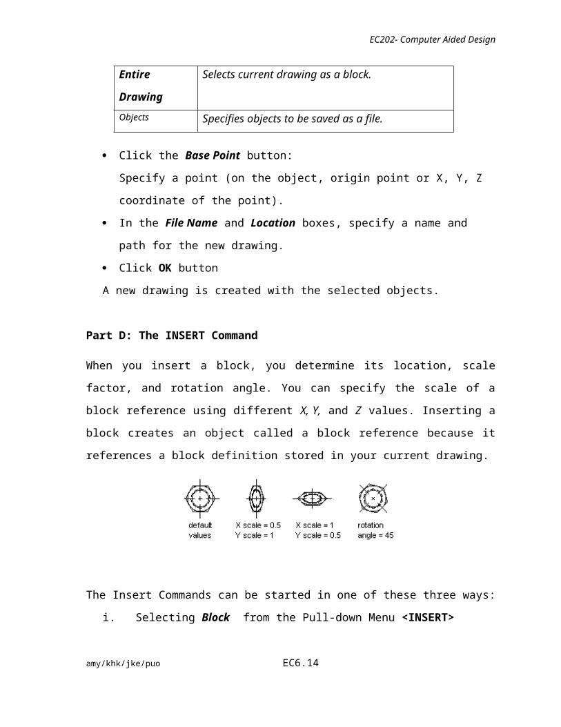
Part D: The INSERT Command
When you insert a block, you determine its location, scale factor, and rotation angle. You
can specify the scale of a block reference using different X, Y, and Z values. Inserting a
block creates an object called a block reference because it references a block definition
stored in your current drawing.
amy/khk/jke/puo EC6.10

EC202- Computer Aided Design
The Insert Commands can be started in one of these three ways:
i. Selecting Block from the Pull-down Menu <INSERT>
Fig. 6.14: Pull-Down Menu <INSERT> e Block
ii. Selecting the icon from the <Draw> Toolbar
Fig. 6.15: Draw Toolbar
iii. Typing insert at the Keyboard and press [Enter]
Fig. 6.16: Keyboard Entry
amy/khk/jke/puo EC6.11

EC202- Computer Aided Design
To INSERT BLOCK in the current drawing
Command: INSERT
An insert dialogue box appears as in Fig. 6.17
Fig. 6.17: An <insert> dialogue box
In the Name box, select a name from a list of block definitions.
The block must already be in the drawing. If you are inserting a drawing file, use the
browse button to locate it.
In the path section, specify the insertion point, scale, and rotation, select Specify
On-Screen. Otherwise, enter values in the Insertion Point, Scale, and Rotation boxes.
If you want the objects in the block to be inserted as individual objects instead of as a
single block, select Explode.
Click the OK button.
The MINSERT Command
The MINSERT command is typically used to insert multiple instances of a block in a
rectangular array. Blocks inserted using MINSERT cannot be exploded. The MINSERT
command is only available from the command line.
To Minsert a command
Create a new object/drawing and do the following command
Command: MINSERT
Enter block name or [?] <Resistor>: or (type for the block name)
amy/khk/jke/puo EC6.12

EC202- Computer Aided Design
Specify insertion point or [Scale/X/Y/Z/Rotate/PScale/PX/PY/PZ/PRotate]: (Click
the required insertion point)
Enter X scale factor, specify opposite corner, or [Corner/XYZ] <1>: 2
Enter Y scale factor <use X scale factor>:
Specify rotation angle <0>: 90
Enter number of rows (---) <1>: 4
Enter number of columns (|||) <1>: 6
Enter distance between rows or specify unit cell (---): 30
Specify distance between columns (|||):40
Up to now, the whole process is simply same with ‘Inserting a block’ which we have already
know. After that, the process proceeds exactly same with ARRAY (rectangular) command.
The EXPLODE Command
The Explode command is used to "explode" single objects back to their constituent parts. In
other words, the command is used to return blocks, polylines etc. (which may be composed
of a number of component objects) back to their individual component parts. The change has
no visible effect.
Toolbar Modify
Pull-down Modify Explode
Keyboard EXPLODE
a. Explode the object by following the instructions below:
Firstly, INSERT an object using the INSERT command.
Next, start the Explode command.
Command: EXPLODE
Select object: (pick the inserted object)
1 object found
Select Object:
Part E: The PRINT Command
amy/khk/jke/puo EC6.13
EC202- Computer Aided Design
There are two methods for producing plots or print in AutoCAD:
From Model Space
Plotting from Model Space is easier to set up, but it can only generate simpler plots.
Plotting from Model Space may also be more difficult to use as you may experience
problems with the margins of the plot being cut off.
From Layout/Paper Space
Plotting from Layout is much more flexible as it allows you to create a plot with many
viewports of different scale, with added raster images, a title block and so on.
Layout view shows the drawing exactly as it going to be printed by the plotter, and it can
also be edited as the normal drawing. Layout (Paper Space) is directly linked to Model
Space, so any change in one space is directly reflected in the other.
Toolbar Standard
Pull-down File Plot
Keyboard PRINT
To produce a plot, you need to follow these steps:
1. Select a plotting device and paper size.
2. Set the scale and select either all or part of the drawing to plot.
3. Preview the plot on the screen.
4. Send the plot to the plotter/printer
5. Monitor plotting progress.
To start the Print Command
1. Create a new drawing or you may open a saved drawing file.
2. Make sure the printer or plotter is turned on and the paper is loaded and ready to
accept the plot information from the computer.
3. Select the print command.
A Print dialogue box as seen in Fig. 7.1 appears on the screen.
amy/khk/jke/puo EC6.14

EC202- Computer Aided Design
Fig. 6.18: Print command setting <plot device)
4. Click the plot device tab and do the following instructions:
Plot Device Options1. Plotter Configuration Select the printer/plotter
(The printer can be selected from the drop down list)
2. Plot Style Table(can choose the colour of the plot, based on the on-screen colours)
None
3. What to plot Current Tab
4. Number of copies Depends on the user
5. Click the Plot Setting Tab and do the following instructions:
amy/khk/jke/puo EC6.15

EC202- Computer Aided Design
Fig. 6.19: Print command setting<plot settings>
Plot Setting OptionsSetting the Paper
size
Select the paper size of the print out (Usually it is the size of the
frame drawn in paper space. In our work, this should be set to A4.
Setting the Drawing
Orientation
Choose either landscape or portrait. For this example set it to
landscape, to match the paper space layout.
Setting the Plot scale This is where the entire paper space scale is set. For the print to
plot to scale, plot scale MUST be set to 1:1. If a quick 'not to
scale' plot is required of a drawing the plot scale can be set to
'scaled to fit' to fill the paper with the selected print area.
Setting the Plot Area We must select which part of the drawing we wish to plot. In this
case, we wish to plot the entire A4 frame in paper space:
Layout - this will plot the current layout/limits
Extents - Similar to zoom extents. The extents of the paper
space area will be plotted.
Display - The current screen display will be plotted.
Window - Similar to zoom window, plot window allows us
to select the exact area to be plotted by selecting
a rectangle around the required area.
amy/khk/jke/puo EC6.16

EC202- Computer Aided Design
Setting the Plot
offset
This enables us to select the position of the plot on the paper. For
best results, select 'centre the plot' to plot the drawing central to
the paper sheet.
Plot Options These settings can be left as they are.
Full preview We can preview the print, but only after we have chosen our plot
setup in 'plot settings'.
Partial preview Provides a simplified preview of the drawing, useful for
previewing large drawings which would take a while to
regenerate all the viewports for the preview.
6. Finally, to exit the preview, right click and select exit. This takes us back to the plot
dialogue box. Go back to the 'plot settings' tab and select the 'plot' button to send the
drawing to the printer.
PART F: EXERCISE
1. Create a new drawing space using the Metric measurement.
2. Set the drawing limits to A4 paper size.
3. Display the grid to the extent of the drawing limits.
4. Create layers and set colours for each layer as below:
i. Transformer
ii. NPN Transistor
iii. AC Generator
iv. Zener diode
v. Potentiometer
vi. Fuse
vii. Ceiling Fan
viii. Miniature Circuit Breaker
ix. Fan
x. Relay
5. Referring to the electronic and electrical symbols shapes at Fig. 6.18 redraw the
diagram at each of the layer created respectively.
6. Make block for each of the symbols created.
7. Print out your drawing on a A4 paper size.
8. Save the drawing file and exit AutoCAD.
amy/khk/jke/puo EC6.17

EC202- Computer Aided Design
Fig 6.18: Electronic and Electrical Schematic symbols
DISCUSSION :
1. When you renamed a layer, what are the characters that AutoCAD won’t accept?
…………………………………………………………………………………………
…………………………………………………………………………………………
2. How do you transfer an object in a layer to another layer?
…………………………………………………………………………………………
…………………………………………………………………………………………
QUESTION :
1. When you create Make Block for an object, what will happen if you give a name
similar to the one already created?
…………………………………………………………………………………………
…………………………………………………………………………………………
amy/khk/jke/puo EC6.18
(1 Marks)
(2 Marks)
(2 Marks)

EC202- Computer Aided Design
2. Before you placed an INSERTed object into its insertion point on the drawing space,
state two (2) ways how that object can be scaled twice than the original size.
.i. .................................................................................................................................
........................................................................................................................................
.......ii.
…………………………………………………………………………………………
…………………………………………………………………………………………
3. At the Print Command dialogue box, you will notice that Drawing Orientation is
already set to Landscape. Suggest a reason.
…………………………………………………………………………………………
…………………………………………………………………………………………
…………………………………………………………………………………………
REFLECTION:
At the end of this practical work, I have learnt that:
…………………………………………………………………………………………………
…………………………………………………………………………………………………
………………………………………………………………………………………………
amy/khk/jke/puo EC6.19
(1 Marks)
(1Marks)
(2 Marks)
(1 Marks)