Final Report: Embankment Quality, Phase 4: Application to Unsuitable Soils
Upload
hany-seif-aldien-nasserCategory
view
294download
17
ISSN 1151-1516
techniques et méthodesdes laboratoires des ponts et chaussées
Guide technique
Practical manualfor the use of soils
and rocky materialsin embankment construction


EXCERPTS from Guide technique “Réalisation des remblais
et des couches de formes” [acronym “GTR”]
(Technical Guideline on “Embankment
and Capping Layer Construction”)
Practical manual
for the
Use of soils and rocky materialsin embankment construction
September 2003
Laboratoire Central des Ponts et Chaussées
58, boulevard Lefebvre - 75732 PARIS Cedex 15 - France

This document has been produced under the joint responsability
of the LCPC and SETRA research organizations
The GTR was drawn up by the following work group:
MM J.-F. CORTÉ LCPC (Division Géotechnique mécanique des chaussées)S.H. EDME Entreprise Müller FrèresA. FÈVRE CETE Normandie-Centre (LRPC de Rouen)D. GILOPPE CETE Normandie-Centre (DESGI)J. GIROUY Direction des Infrastructures du Département de la Charente-MaritimeH. HAVARD CETE de l’Ouest (LRPC d’Angers)J.-P. JOUBERT SETRAG. MOREL CER de RouenA. PERROT CETE de l’Est (LRPC de Nancy)B. de PILLOT CETE de Lyon (DES)J.-P. PUECH ScétaurouteD. PUIATTI Société des Chaux et Dolomies du Boulonnais S.A.M. SCHAEFFNER LCPC (Division Géotechnique mécanique des chaussées)B. URCEL DDE des Hauts-de-Seine
and written by:
MM J.-F. CORTÉ LCPC (Division Géotechnique mécanique des chaussées)A. FÈVRE CETE Normandie-Centre (LRPC de Rouen)H. HAVARD CETE de l’Ouest (LRPC d’Angers)J.-P. JOUBERT SETRAM. KERGOET LRPC de l’Est parisienG. MOREL CER de RouenA. PERROT CETE de l’Est (LRPC de Nancy)A. QUIBEL CER de RouenM. SCHAEFFNER LCPC (Division Géotechnique mécanique des chaussées)J. VEYSSET CETE de Lyon (LRPC de Lyon)
Under responsibility of Scientific and Technical Network of the french Ministery of Equipement
This Practical Manual was prepared by:
MM J.-F. CORTÉ LCPC (Direction technique “Chaussées”)H. HAVARD LCPC (Direction technique “Géotechnique”)
And translated by:
NORTRAD
and the translation kindly reviewed by:
Mme J. DEZART Entreprise Guintoli (France)
The distribution of this document is supported by:
To order this publication:
Laboratoire Central des Ponts et Chaussées - IST - Diffusion des Editions - 58, boulevard Levebvre F - 75732 - Paris Cedex 15 - Phone: 01 40 43 50 20 - Fax: 01 40 43 54 95 - Internet: http://www.lcpc.frPrice: 23 Euros HT
This document is property of the LCPC organization and may not be copied or reproduced in any form, even partially,without the express authorization of the LCPC Managing Director (or one of the Director’s authorized representatives).© 2003 - LCPCISSN 1151-1516ISBN 2-7208-3116-4

3
Table of contents
Notice 5
1. Field of application 72. References 72.1 Bibliography and Technical References 72.2 Relevant Standards 83. Abbreviations and symbols 9
4. Classification of rocks and soils 10
4.1 Rock and Materials Displaying Special Behaviour 104.2 Soils 144.2.1 Grain size characteristics 144.2.2 Clay characteristics 144.2.3 State characteristics 154.3 Summary of classification 174.3.1 Summary table of the classification of rock and soil types 174.3.2 Classification according to type and state 18
5. Use of rocks and soils in embankment construction 26
5.1 Rock and Materials Displaying Special Behaviour 275.2 Soils 29
6. Compaction of fill 36
6.1 Definition of specifications 366.2 Classification of compaction plant 376.2.1 Pneumatic tyred rollers (Pi) 376.2.2 Smooth vibrating drum rollers (Vi) 376.2.3 Vibrating rollers (VPi) 406.2.4 Static tamping rollers (SPi) 406.2.5 Vibrating plate compactors (PQi) 406.3 Compaction specifications 416.3.1 Use of Tables - Examples of Application 416.3.2 Compaction tables 436.4 Continuous monitoring of compaction 546.4.1 Specifications 546.4.2 Monitoring Operations 55
7. Particular case of use of arid soils 57
7.1 Advantages of, and basis for dry compaction 577.2 Definition of arid soils - Application scope of the method 577.2.1 Nature of concerned soils 577.2.2 Definition of moisture state “arid” 577.2.3 “Arid” state classes of soils 587.2.4 Acceptable embankment height 587.3 Compaction tables 587.4 Particularities of dry compaction 587.5 “Dry compaction” trial embankments 597.6 Special site organisation for “Dry compaction” 59


5
Notice
This Manual is an excerpt from the Technical Guidelines on Embankmentand Capping Layers Construction (abbreviated to its French acronym GTR) issuedSeptember 1992 in France by LCPC 1 and SETRA 2. The Guidelines are the basic standard
engineering reference work in France on the construction of embankments and capping layers.This excerpt from the Guidelines concerns only the part dealing with the classification of naturalsoils and their use in embankments (excluding all reference to organic topsoils and industrial products)and requirements for their use in capping layers construction).
This Manual is a broader development of a more specific project undertaken in 1998 at the request of the Executive Council for Major Works in Lebanon with a view to compiling a Lebanesestandard on the construction of fill structures under the aegis of LIBNOR.
The GTR rock classification system (see section 4-1 below) addresses only those rockscommonly found in France. Experience has shown that the use of the Manual in another countrymay justify reducing or extending the classification system to adapt its content to the rocksencountered with respect to earthmoving work not included in GTR, if such changes wereconsidered relevant.These changes do not appear to be required in the soil classification system(see section 4-2).
Earthworks in specific meteorological area (for instance very hot or very cold ones) needadaptations to take into account difficulties produced by natural moisture content.
Caveat Language - This practice offers a set of instructions for performing one or more specificoperations. This document cannot replace education and experience and should be used inconjunction with professional judgment. Not all aspects of this practice may applicable in allcircumstances. This manual is not intended to represent or replace the standard of care by whichthe adequacy of a given professional service must be judged, nor should this document beapplied without consideration of a project’s many unique aspects.
1. Laboratoire Central des Ponts et Chaussées, 58 boulevard Lefebvre, 75732 Paris Cedex 15, France,
tel. (33) 1 40 43 50 00, fax (33) 1 40 43 54 98
2. Service d'Etudes des Routes et Autoroutes, Centre de Sécurité et des Techniques Routières, 46 avenue Aristide Briand, BP 100,
92223 Bagneux Cedex, France, tel. (33) 1 46 11 31 31, fax (33) 1 46 11 31 69


7
Use of soils and rocky materials in embankment construction • Field of application
1. Field of application
This Manual- classifies naturally-occurring soils on the basis of laboratory classification tests (chiefly with respect
to their potential use as a fill material),- specifies the soil categories suitable for incorporation in embankments and the relevant conditions
of use,- describes the main methods construction and any restrictions specific to categories.
The section dealing with compaction of fill puts forward a suggested classification of compactionmachinery offering a standard of construction compatible with the quality goals commonlyassociated with such work, and a method for continuously monitoring actual compaction performance.
A special method of compaction of “arid” soils often found in arid countries is also proposed inchapter 7. The particular precautions mentioned in this chapter are then required.
This method is not a substitute for proper design, which must address project-specific factors suchas available soil types and condition, balanced cut and fill, conditions in the underlying ground,embankment structure when the constituent soils are not uniform, embankment face slopes,drainage, local climate and weather conditions over the construction period, erosion risk, etc. In addition to the rules of the present document, it is necessary to carry out a specific stabilitystudy for embankments the height of which exceed 15 to 20 metres.
2. References
2.1 Bibliography and Technical References
This Manual is an excerpt from the Technical Guidelines on Embankment and Capping Layer
Construction (abbreviated to its French acronym GTR) issued September 1992 in France byLCPC3 and SETRA4. The Guidelines are substantially the only standard engineering referencework in France for the construction of embankments and capping layers. This Manual concernsonly the part of the Guidelines dealing with the classification of natural soils and their use inembankments. Reference should be made to the Guidelines for detailed explanation and in somecases engineering justification for the arrangements recommended herein, because the Manualtakes only the practical recommendations from the Guidelines, to avoid overburdening the work.It is however important to note that the Manual differs from the Guidelines in the following
respects:
- Organic topsoils and industrial products in the GTR classification have been ignored becausetheir use is too dependent on environmental legislation and cannot be readily transposed fromone country to another.
- Soil class D3 has been deleted from the classification (being not necessary).- Criteria for use which involves specific plant (full-depth excavation or bench excavation) or
modification of the soil moisture state (particularly wetting over-dry material) have not been keptbecause they are likely to be difficult to meet in the field. Nevertheless, if site conditions aresuch as to allow the soil moisture to be improved or even completely changed, this fact isaddressed in the Manual in the site condition classification.
3. Laboratoire Central des Ponts et Chaussées, 58 Boulevard Lefebvre, 75732 Paris Cedex 15, France,
tel. (33) 1 40 43 50 00, fax (33) 1 40 43 54 98
4. Service d'Etudes des Routes et Autoroutes, Centre de Sécurité et des Techniques Routières, 46 Avenue Aristide Briand, BP 100,
92223 Bagneux Cedex, France, tel. (33) 1 46 11 31 31, fax (33) 1 46 11 31 69

8
Use of soils and rocky materials in embankment construction • References
The engineering justification of the content of this document has been establishedexperimentally by the systematic use, from 1976 to 1992, of very similar rules to those in the GTR,laid down at the time by Recommendations on Road Earthworks (abbreviated RTR, a documentgiven official status in France at the time by the standard public contract specifications forhighways), which very broadly speaking, led to stable fill structures being built. Experienceacquired and records of construction conditions and performance of the structures built in thisway led to improvements to the RTR on several points when preparing the Technical Guidelineson Embankment and Capping Layer Construction (GTR). Apart from the experimental justificationoffered by successful projects, extensive trials had been conducted under controlled conditions,especially for drafting the compaction specifications.
The justifications of the particular method proposed for re-use of arid soils can be found in thechapter 7.
2.2 Relevant Standards
The Manual makes reference to the following French standards issued by AFNOR (AssociationFrançaise de Normalisation, Tour Europe, 92049 Paris La Défense Cedex, France):XP P 18-540 - Aggregate - Definitions, Compliance, Specifications (Oct. 1997)5 XP P 18-572 - Micro-Deval Abrasion Test (Dec. 1990)5 XP P 18-573 - Los Angeles Test (Dec. 1990)XP P 18-574 - Dynamic Fragmentation Test (Dec. 1990)XP P 18-576 - Determination of Sand Friability Coefficient (Dec. 1990)XP P 18-593 - Sensitivity to Frost (Dec. 1990)5XP P 18-598 - Sand Equivalent (Oct. 1991)
NF P 11-300 - Earthwork Construction - Classification of materials for use in the constructionof highway embankments and capping layers (Sept. 1992)NF P 11-301 - Earthwork Construction - Terminology (Dec. 1994)NF P 94-040 - Soils: Investigations and Tests - Simplified method of classifying the 0-50mm fraction of granular material - Determination of grain sizes and methyl blue value(Oct. 1993)NF P 94-049-1 - Soils: Investigations and Tests - Determination of moisture content (by weight) of materials - Part 1: Microwave oven drying method (Feb. 1996)NF P 94-049-2 - Soils: Investigations and Tests - Determination of moisture content (by weight) of materials - Part 2: Hotplate and radiator methods (Feb. 1996)NF P 94-050 - Determination of moisture content (by weight) of materials - Autoclavemethod (Sept. 1995)NF P 94-051 - Soils: Investigations and Tests - Determination of Atterberg Limits - Liquidlimit (cup method) - Plastic limit (roll method) - March 1993NF P 94-052-1 - Soils: Investigations and Tests - Determination of Atterberg Limits - Part1 - Liquid limit (cone penetration method) (Nov. 1995)NF P 94-054 - Soils: Investigations and Tests - Determination of unit weight of solid particles- Water pycnometer method (Oct. 1991)NF P 94-056 - Soils: Investigations and Tests - Grain size analysis - Wash, dry and screenmethod (March 1996)NF P 94-061-1 - Soils: Investigations and Tests - Determination of unit weight of in-placematerial - Part 1 - Direct transmission probe gammadensimeter method (Oct. 1996)NF P 94-061-2 - Soils: Investigations and Tests - Determination of unit weight of in-placematerial - Part 2 - Membrane densimeter method (March 1996)
NF P 94-061-3 - Soils: Investigations and Tests - Determination of unit weight of in-placematerial - Part 3 - Sand method (April 1996)
5. This standard remains valid but will be superseded on 1st December 2003 by a European standard already issued, designated NF EN.

9
Use of soils and rocky materials in embankment construction • Abbreviations and symbols
NF P 94-061-4 - Soils: Investigations and Tests - Determination of unit weight of in-placematerial - Part 4 - Method for coarse materials (Dmax > 50mm) (Dec. 1996)NF P 94-062 - Soils: Investigations and Tests - Determination of in-place unit weight - Twinprobe gamma diagraphy (11 pages) (Aug. 1997)XF P 94-063 - Soils: Investigations and Tests - Compaction testing - Constant energypenetrometer method - Principle and method of calibrating penetrodensitographs - Reductionof results - Interpretation (Aug. 1997)NF P 94-064 - Soils: Investigations and Tests - Dry unit weight of rock element - Hydrostaticweighing method (Nov. 1993)NF P 94-066 - Soils: Investigations and Tests - Fragmentation coefficient of rock material(Dec. 1992)NF P 94-067 - Soils: Investigations and Tests - Degradability coefficient of rock material(Dec. 1992)NF P 94-068 - Soils: Investigations and Tests - Determination of methyl blue absorptioncapacity of soil and rock material by the stain test (Oct. 1998)NF P 94-078 - Soils: Investigations and Tests - Post-immersion CBR - Immediate CBR -Immediate bearing index IPI - Determination on sample compacted in CBR mould (May 1997)NF P 94-093 - Soils: Investigations and Tests - Determination of compaction references ofmaterial - Proctor normal test - Modified Proctor test (Oct. 1999)NF P 94-100 - Soils: Investigations and Tests - Materials treated with lime and/or hydraulicbinders - Soil treatment suitability test (Aug. 1999)
NF P 98-705 - Highway construction and maintenance plant and equipment - Compactionplant and equipment - Terminology and trade specifications (1992)NF P 98-713 - Qualification of roadmaking plant and equipment - Methods for testingcompaction plant performanceNF P 98-736 - Highway construction and maintenance plant and equipment - Classificationof compaction plantNF P 98-760 - Highway construction and maintenance plant and equipment - Pneumatictyred rollers - Evaluation of soil contact pressure (1992)NF P 98-761 - Highway construction and maintenance plant and equipment - Compactionplant - Evaluation of eccentric moment (1992)NF P 98-234.2 - Carriageway tests - Frost performance - Part 2 - Frost swelling test fortreated and untreated soils and granular materials with Dmax = 20mm (Feb. 1996)
3. Abbreviations and symbols
The following abbreviations and symbols are used in this Manual.
LH Hydraulic binders
Soil state th very weth wetm moderately wets dryts very dry
Test results DG Degradability coefficient (%)Dmax Maximum soil grain size (mm)ES Sand equivalent (%)FR Fragmentation coefficient (%)FS Sand friability coefficient (%)Ic Consistency index

10
Use of soils and rocky materials in embankment construction • Classification of rocks and soils
Ip Plasticity index (%)IPI Immediate bearing index (%)LA Los Angeles coefficient (%) measured on 10-14mm fraction
(if unavailable, on 6.3-10mm fraction)MDE Micro-Deval coefficient in water (%) measured on 10-14mm fraction
(if unavailable, on 6.3-10mm fraction)VBS Methyl blue absorption of soil measured on 0-50mm fraction
(grams methyl blue per 100g soil)wn Natural moisture content (%) wOPN Standard Proctor optimum moisture content (%)ρd Bulk unit weight of dry rock sample
4. Classification of rocks and soils
4.1 Rock and materials displaying special behaviour
Prior to excavation, a material may often look like rock and one cannot decide just what type ofsoil it will form after removal. Some more or less loose materials may also display specialbehaviour on excavation, during placement and/or in the completed works, so that the classificationsystem presented below in section 4-2 cannot adequately describe them (chalk is an exampleof this).Such materials must nevertheless be characterised at the design stage in order to plan how theycan be used in the works and what difficulties their behaviour might present. Usually, engineerssimply classify the resulting soil except if the class assigned in this section to the original rock,juxtaposed with the soil classification, adds extra information which can be usefully preserved inview of the special behaviour of the resulting soil (as with chalk).
The characterisation of such materials (rock and materials displaying special behaviour)
begins by naming the material in geological terms.
The materials listing below is based on experience gained in France up to the present time,considered relevant to earthwork construction. It might be expanded as needs arise and moreknowledge is amassed.
R1
CHALKS
a - Description
Material formed by the accumulation offalling calcite particles of the order of 1 to10 μm in size.This structure is all the more fragile in thatthe material is very porous (or conversely,its dry density is low).During earthmoving operations, it producesa quantity of fines, directly related to thefragile accumulative structure.When chalk is saturated or near-saturated,the pore water wets these fines so that theybehave like a paste, hampering themovement of the construction plant and Earthworks in chalk.

11
Use of soils and rocky materials in embankment construction • Classification of rocks and soils
causing pore pressures to build up in the fill.Conversely, dry chalk is a rigid material with good load-bearing performance, but compactionis difficult.Some very wet low density chalks may continue to fragment after they are placed mainly dueto applied stresses and frost.
b - Classification
Chalks are classified according to their dry density ρd and moisture content wn as shown below
ρd > 1.7 R11
1.5 < ρd � 1.7 and wn � 27 R12 h1.5 < ρd � 1.7 and 22 � wn < 27 R12 m1.5 < ρd � 1.7 and 18 � wn < 22 R12 s1.5 < ρd � 1.7 and wn < 18 R12 ts
ρd � 1.5 and wn � 31 R13 thρd � 1.5 and 26 � wn < 31 R13 hρd � 1.5 and 21 � wn < 26 R13 mρd � 1.5 and 16 � wn < 21 R13 sρd � 1.5 and wn < 16 R13 ts
R2
SUNDRY CALCAREOUS ROCKS
(Coarse-grained limestone, travertine, massive limestone, etc.)
a - Description
This class contains the whole range of calcareous rock materials. Their predominant featurein respect of their use in fill is their friability and, for the more fragmentable materials, frostsusceptibility. Broadly speaking, the materials are not evolutive rock materials (see argillaceousrock below) and raise no particular problems when used in fill.Because of their friability, attrition and crumbling may produce fines liable to make thematerial sensitive to water under heavy traffic.
b - Classification
The more compact calcareous rocks areclassified according to their resistancein the micro-Deval test, while softer rocksare classified according to their bulk unitweight:
MDE � 45 R21
MDE > 45 and ρd > 1.8 R22
ρd � 1.8 R23
Earthworks in limestone.

12
Use of soils and rocky materials in embankment construction • Classification of rocks and soils
R3
ARGILLACEOUS ROCKS
(Marls, shales, claystone, pelite, etc.)
a - Description
They are characterised by a more or less resistant(usually carbonate) structure with a highly variableproportion (5 % to 95 % from what is generallyreported) of potentially swelling clay mineralsimprisoned. They fragment to varying degreeswhen worked, freeing plastic, water-sensitivefines. Breakdown of the structure may continuesubsequent to being placed, under the mechanicalstresses applied by the overlying fill, and throughweathering of large pieces of intact rock due toswelling of the clay minerals in contact with watercausing destruction of the rock skeleton. Thisprocess and associated distress to the fill is morelikely when the materials are less fragmentedand display uniform grain size in the completedfill.For the more fragmentable rocks (class R34),their 0-50mm fraction must be characterised.
b - Classification
The evolutive nature of these rocks is determinedby two tests:• Fragmentation test (to French standard NF P
94-066) to assess, from the FR results, thesensitivity of the rock to the fragmentation energyapplied on site.
• Degradability test (to French standard NF P 94-067) to evaluate, from the DG result, theweathering resistance in contact with water bymeasuring the effects of wetting and dryingcycles.
For the more fragmentable rocks (class R34
materials), the natural moisture content wn iscompared to their normal Proctor optimum wOPN
or their immediate bearing index IPI is measuredto determine their hydrous state.These rocks therefore classify as follows:
* Values in italics are recommended
Fragmentability Degradability Class
FR � 7 DG > 20 R31
5 < DG � 20 R32
DG � 5 R33
FR > 7 [wn � 1.3 wOPN or IPI < 2*] R34th[1.1 wOPN � wn < 1.3 wOPN or 2 � IPI > 5*] R34h
0.9 wOPN � wn < 1.1 wOPN R34m0.7 wOPN � wn < 0.9 wOPN R34s
Rocky marls evolving from a sound, just extracted state (1) to a clay (3) by the halfway of (2).
1
2
3

13
Use of soils and rocky materials in embankment construction • Classification of rocks and soils
R4
SILICEOUS ROCKS
(sandstone, puddingstone, breccia, etc.)
a - Description
This class of materials can be likened toassemblies of sand grains (as in sandstone)or stones (breccia and puddingstone)cemented together with silica or calcite.The strength of the binding material affectsthe behaviour of the rock (in particular thereis a risk of rearrangement after placementif not sufficiently compacted). If the rock isfragmentable, the ultimate evolution ceaseswith the release of the constituent grains orstones. Some also contain enough clay tomake them behave in a manner similar toclass R34 material.
b - Classification
The more compact rocks are classified according to their strength in the Los Angeles fragmentationtest and micro-Deval wear test, the softer rocks according to their fragmentability.
R5
SALINE ROCKS
(Gypsum, rock salt, anhydrite, etc.)
a - Description
In mechanical terms, this class of materials are like class R2 and R3 but they are more soluble inwater and are therefore liable to cause distress in the structure, especially when- the salt is highly soluble- it accounts for a high proportion of the rock- its fragmentability on placement is low (making the fill highly pervious).
b - Classification
R6
IGNEOUS AND METAMORPHIC ROCKS
(Granite, basalt, trachyte, andesite, etc., gneiss, schist, slate, etc.)
a - Description
This class of materials may have widely differing mechanical properties. Their fragmentability andfriability may be very variable (low to very high).Class R61 and R62 materials do not weather inthe fill due to stresses and water but class R63 displays similar behaviour to classes R34 or R43.
Cut in vosgian sandstone.
Soluble salt content (depending on degree of fragmentability):� 5-10 % in rock salt R51
� 30-50 % in gypsum
Soluble salt content (depending on degree of fragmentability):� 5-10 % in rock salt R52
� 30-50 % in gypsum
LA � 45 and MDE � 45 R41
LA > 45 or MDE > 45and FR � 7 R42
FR > 7 R43

14
Use of soils and rocky materials in embankment construction • Classification of rocks and soils
b - Classification
The more compact rocks are classifiedaccording to their strength in the LosAngeles fragmentation test and micro-Deval wear test, the softer rocks accordingto their fragmentability.
4.2 Soils
In attempting to classify a soil on the basis of criteria capable of determining its suitability as filland associated conditions for its placement, three parameters must be determined.
4.2.1 Grain size characteristic
These characteristics are derived simply from the grain size analysis.
Dmax: size of largest grains
Note. A D3 class is proposed in GTR for Csoils which have a methyl blue value(VBS) of less than 0.1 and less than12 % passing the 80 μm sieve.
4.2.2 Clay characteristics
These characteristics are evaluated fromthree tests:• Atterberg limits (plastic index Ip)• Methyl blue absorption value of soil (VBS)• Sand equivalent (ES)
Earthworks in basalt.
Methyl Blue Test.
100%
35%
12%
0 50mm Dmax*
0/50mm fractionpassing 80 μm
LA � 45 and MDE � 45 R61
LA > 45 or MDE > 45and FR � 7 R62
FR > 7 R63
FINE SOILS A
FINES-RICH SAND OR
GRAVEL SOILS
B5
or B6
Passing 2mm
> 70% < 70%
SAND SOILS GRAVEL SOILS
D1, B
1, B
2D
2, B
3, B
4
FINES-POOR
COARSE AND POORLY
STRUCTURED SOILS C1
(rounded grains or more than 60 to 80% fraction 0/50mm in the soil)
COARSE AND
STRUCTURED SOILS C2
(angular grains and less than 60 to 80% fraction 0/50mm in the soil)

15
Use of soils and rocky materials in embankment construction • Classification of rocks and soils
The grain size classification (section 4-2-1 above) can be completed as follows:
• Fine soils
2.5 6 8 VBS
12 25 40 Ip
A1
A2
A3
A4
• Fines-rich sand and gravel soils
1.5 VBS
12 Ip
B5
B6
• Fines-poor sand soils
0,1 0,2 VBS
35 ES
D1
B1
B2
• Fines-poor gravel soils
0,1 0,2 VBS
25 ES
D2
B3
B4
Note. Values in italics (e.g. 0,2) are recommended, especially for contract specifications, inpreference to other limit values.
4.2.3 State characteristics
Assessing the wetness of a soil (when itis “sensitive” to water) is based on its IPIvalue or on its natural moisture content wn
at a given time in relation to the optimummoisture content wOPN determined fromthe standard Proctor test on the fractionsmaller than 20mm, or on the value ofthe soil consistency index.
Five hydrous states are considered:
ts: (very dry) / s: (dry) / m: (normal) /
h: (wet) / th: (very wet)
The normal state (m) is the best condition for placement, in particular, it allows appropriatecompaction to be achieved. Wet (h) and very wet (th) states are soils for which trafficability andcompaction are difficult (a very wet soil is not normally trafficable for a standard earthmoving plant).The dry (s) and very dry (ts) states are soils which are difficult to compact to form stable fill structures(a very dry soil is considered as being impossible to compact properly by standard methods).
Soils in a very wet state.

16
Use of soils and rocky materials in embankment construction • Classification of rocks and soils
Soils are classified according to their hydrous state as follows.
Note. Values in italics (e.g. 0.9) are recommended, especially for contract specifications, inpreference to other limit values, when there is a choice.
EXAMPLES OF CLASSIFICATION
Rocks not extracted with explosives and materials displaying special behaviour
• R32: argillaceous rock (e.g. classified marl or claystone), may contain carbonate fraction, the 0-50mm fraction registers less than 7 in the fragmentation test and 5-20 in the degradability test.
• R41: siliceous rock (e.g. classified sandstone) with Los Angeles coefficient less than 45 and micro-Deval coefficient also less than 45.
• Rock classified limestone with MDE greater than 45 and bulk unit weight ρd 1.84 -> class R22.
Soils
• A2m: fine soil with plastic index between 12 and 25 with normal moisture content (IPI between5 and 15).
• C1-B5h: soil with a fraction larger than 50mm representing less than 20-40% of whole soil sampleand/or with large rounded particles. The fraction smaller than 50mm is sand or gravel with aplasticity index below 12 in the normally wet state.
• C2-D2: soil with a fraction larger than 50mm representing not less than 20-40% of whole soilsample with angular particles. The fraction smaller than 50mm is clean gravel and thereforeinsensitive to water, so its moisture content does not need to be characterised.
• Soil with:17% passing 80μm andDmax: 40mm -> class B5 or B6
VBS: 1,7 -> class B6
IPI: 7 -> class B6h
Soil type Reference testState threshold
ts s m h th
A1 IPI 25 8 3
wn/wOPN 0.7 0.9 1.1 1.25A2 IPI 15 5 2
wn/wOPN 0.7 0.9 1.1 1.3Ic 1.4 1.2 1.05 0.9
A3 IPI 10 3 1
wn/wOPN 0.7 0.9 1.2 1.4Ic 1.3 1.15 1 0.8
A4 Special study required
B1 No sens iv i ty to water content
B2 IPI 8 4
wn/wOPN 0.5 0.9 1.1 1.25
B3 No sens iv i ty to water contentB4 IPI 15 7
wn/wOPN 0.6 0.9 1.1 1.25B5 IPI 30 12 5
wn/wOPN 0.6 0.9 1.1 1.25B6 IPI 25 10 4
wn/wOPN 0.7 0.9 1.1 1.3Ic 1.3 1.2 1 0.8

17
Use of soils and rocky materials in embankment construction • Classification of rocks and soils
• Soil with:55% of 0-50mm fraction passing 80 μm and Dmax: 70mm andCoarse particles (> 50mm) are rounded -> class C1-AIp: 32 -> class C1-A3
wn/wOPN: 1 -> class C1-A3m
• Soil with:10% of 0-50mm fraction passing 80μm and55% of 0-50mm fraction passing 2mm andDmax: 100mm andCoarse particles (> 50mm) are angular and48% of the complete soil sample passing 50 mm -> class C2 (D2, B3 or B4)VBS: 0.13 -> class C2-B3
Material known to be almost completely insensitive to water, so its moisture content does notneed to be characterised.
4.3 Summary of classification
4.3.1 Summary table of the classification of rock and soil types
SoilsDmax � 50mm
SoilsDmax > 50mm
Rocks
A1 A2 A3 A4
B5 B6
D1 B1 B2
D2 B3 B4
Percent passing 80 μm
100%
35%
12%
0%0 0,1 0,2 1,5 2,5 6 8
12 25 40 Ip
Percent passing 2 mm
100%
70%
0%
C1 or C2
C1: poorly structured rounded or angular
materials with fraction
0/50mm > 60-80%
C2: strongly structured angular materials
with fraction
D3 0/50mm < 60-80%
Percent passing 80 μm
fraction 0/50mm
12 %
0 0,1 VBS
VBS
Carbonate rocks Chalk R1
Limestone R2
Sedimentary rocks Argillaceous rocks Marls, claystone, pelite, etc. R3
Siliceous rocks Sandstone, puddingstone, breccia, etc. R4
Saline rocks Rock salt, gypsum, etc. R5
Igneous and Granite, basalt, andesite, gneiss, schist, slate, etc. R6metamorphic rocks

18
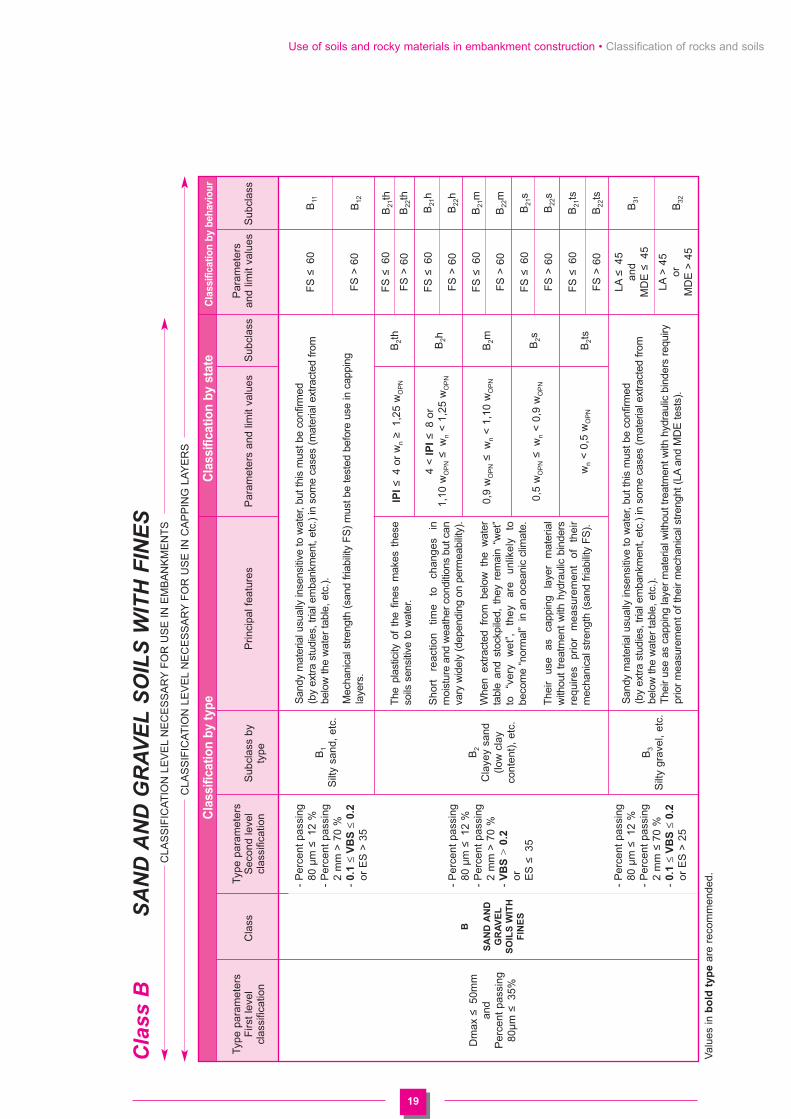
Use of soils and rocky materials in embankment construction • Classification of rocks and soils
4.3
.2 C
lassif
ica
tio
n a
cco
rdin
g t
o t
yp
e a
nd
sta
te
Cla
ss A
FIN
E S
OIL
SV
alu
es i
n b
old
typ
e a
re r
eco
mm
en
ded
IPI
≤3
or w
n�
1,25
wO
PN
3 <
IPI
≤8
or
1,10
wO
PN�
wn
< 1
,25
wO
PN
8 <
IP
I �
25 o
r
0,9
wO
PN�
wn
< 1
,10
wO
PN
0,7
wO
PN�
wn
< 0
,9 w
OP
N
wn
< 0
,7 w
OP
N
IPI
≤2 o
r Ic
≤0,9
orw
n�
1,3
wO
PN
2 <
IPI
≤5 o
r 0,9
<Ic
≤1,0
5
or 1
,1 w
OP
N�
wn
< 1
,3 w
OP
N
5 <
IP
I �
15 o
r 1,
05 <
Ic �
1,2
or 0
,9 w
OP
N�
wn
< 1
,1 w
OP
N
1,2
< I
c �
1,4
or0,
7 w
OP
N�
wn
< 0
,9 w
OP
N
Ic >
1,4
or
wn
< 0
,7 w
OP
N
IPI
≤1 o
r Ic
≤0,8
or
wn�
1,4
wO
PN
1 <
IPI
≤3 o
r 0,8
<Ic
≤1 o
r1,
2 w
OP
N�
wn
< 1
,4 w
OP
N
3 <
IP
I �
10 o
r 1
< I
c �
1,15
or
0,9
wO
PN�
wn
< 1
,2 w
OP
N
1,15
< I
c �
1,3
or0,
7 w
OP
N�
wn
< 0
,9 w
OP
N
Ic >
1,3
or
wn
< 0
,7 w
OP
N
The
hyd
rous
sta
te t
hres
hold
s ca
nbe
pro
vide
d by
a s
peci
al s
tudy
.
Sm
all c
hang
es in
moi
stur
e co
nten
t pr
oduc
e su
dden
cha
nges
in c
onsi
sten
cy,
espe
cial
ly w
hen
wnis
clo
se t
o w
OP
N.
Rel
ativ
ely
shor
t rea
ctio
n tim
e to
cha
nges
in m
oist
ure
and
wea
ther
con
di-
tions
but
per
mea
bilit
y m
ay v
ary
wid
ely
depe
ndin
g on
gra
ding
,pl
astic
ity a
nd c
ompa
ctne
ss,
so t
here
can
be
a w
ide
varia
tion
in r
eact
ion
time.
With
low
pla
stic
ity f
ine
soils
, it
is f
requ
ently
pref
erab
le t
o id
entif
y th
em b
y th
eir
met
hyl
blue
VB
S v
alue
beca
use
of th
e la
ck o
f pre
cisi
on in
mea
surin
g Ip
.
The
mid
-ran
ge n
atur
e of
thi
s su
bcla
ss m
eans
the
y ar
e su
ita-
ble
for
use
with
mos
t ty
pes
of c
onst
ruct
iona
l pl
ant
prov
ided
m
oist
ure
cont
ent
is n
ot t
oo h
igh.
Ip
is t
he b
est
iden
tific
atio
ncr
iterio
n.
The
se s
oils
are
hig
hly
cohe
sive
at
mod
erat
e to
low
moi
stur
eco
nten
ts a
nd s
ticky
or
slip
pery
in t
he w
et s
tate
mak
ing
them
di
fficu
lt to
wor
k w
ith o
n si
te (
or i
n th
e la
bora
tory
). T
heir
low
pe
rmea
bilit
y m
eans
that
in-p
lace
cha
nges
in m
oist
ure
cont
ent
take
pla
ce v
ery
slow
ly.
Moi
stur
e co
nten
t m
ust
be i
ncre
ased
si
gnifi
cant
ly b
efor
e th
ere
is a
ny s
igni
fican
t ch
ange
in
cons
is-
tenc
y.
The
se s
oils
are
ver
y co
hesi
ve a
nd a
lmos
t im
perm
eabl
e. T
heir
moi
stur
e c
onte
nt is
cha
ngin
g ve
ry s
low
ly w
ith la
rge
shrin
kage
or s
wel
ling.
The
ir us
e in
em
bank
men
t is
gen
eral
ly e
xclu
ded,
but
may
be
resu
lted
from
a s
peci
al s
tudy
with
eve
ntua
lly
in-s
ite tr
ials
.
A1
Low
pla
stic
ity s
ilts,
loes
s, a
lluvi
al s
ilts,
clea
n fin
e sa
nd, l
owpl
astic
ity g
rani
tesa
nd.
A2
Cla
yey
fine
sand
, si
lt, lo
w p
last
icity
clay
s an
d m
arls
, gr
anite
san
d, e
tc.
A3
Cla
y an
d m
arl c
lay,
high
pla
stic
ity s
ilts,
etc. A4
Cla
y an
d m
arl c
lay,
very
hig
h pl
astic
ity,
etc.
VB
S ≤
2,5
orIp�
12
12 <
Ip ≤
25
or2,
5 <
VB
S �
6
25 <
Ip ≤
40
or6
< V
BS
�8
Ip >
40
orV
BS
> 8
A
FIN
E
SO
ILS
Dm
ax �
50m
man
dP
erce
nt p
assi
ng80
μm >
35%
A1t
h
A1h
A1m A1s
A1t
s
A2t
h
A2h
A2m A2s
A2t
s
A3t
h
A3h
A3m A3s
A3t
s
A4t
h
A4h
A4m A4s
Cla
ssif
ica
tio
n b
y t
yp
eC
lassif
ica
tio
n b
y s
tate
Type
par
amet
ers
Type
par
amet
ers
Sub
clas
s by
Firs
t le
vel
Cla
ssS
econ
d le
vel
type
Prin
cipa
l fea
ture
sP
aram
eter
s an
d lim
it va
lues
Sub
clas
scl
assi
ficat
ion
clas
sific
atio
n
Val
ues
in b
old
typ
ear
e re
com
men
ded.
19
Use of soils and rocky materials in embankment construction • Classification of rocks and soils
Cla
ss B
SA
ND
AN
D G
RA
VE
L S
OIL
S W
ITH
FIN
ES
CLA
SS
IFIC
AT
ION
LE
VE
LN
EC
ES
SA
RY
FO
R U
SE
IN
EM
BA
NK
ME
NT
S
CLA
SS
IFIC
AT
ION
LE
VE
LN
EC
ES
SA
RY
FO
R U
SE
IN
CA
PP
ING
LA
YE
RS
Val
ues
in b
old
typ
ear
e re
com
men
ded.
B
SA
ND
AN
D
GR
AV
EL
SO
ILS
WIT
H
FIN
ES
Dm
ax �
50m
man
d P
erce
nt p
assi
ng
80μ
m �
35%
- P
erce
nt p
assi
ng
80 μ
m �
12 %
- P
erce
nt p
assi
ng
2 m
m >
70
%-
0.1
≤V
BS
≤0.2
or E
S >
35
- P
erce
nt p
assi
ng
80 μ
m �
12 %
- P
erce
nt p
assi
ng
2 m
m >
70
%-
VB
S >
0.2
or
ES
�35
- P
erce
nt p
assi
ng
80 μ
m �
12 %
- P
erce
nt p
assi
ng
2 m
m �
70
%-
0.1
≤V
BS
≤0.2
or E
S >
25
B1
Silt
y sa
nd,
etc.
B2
Cla
yey
sand
(low
cla
yco
nten
t),
etc.
B3
Silt
y gr
avel
, et
c.
The
pla
stic
ity o
f th
e fin
es m
akes
the
seso
ils s
ensi
tive
to w
ater
.
Sh
ort
re
act
ion
tim
e
to
cha
ng
es
in
moi
stur
e an
d w
eath
er c
ondi
tions
but
can
vary
wid
ely
(dep
endi
ng o
n pe
rmea
bilit
y).
Whe
n ex
trac
ted
from
bel
ow t
he w
ater
tabl
e an
d st
ockp
iled,
the
y re
mai
n “w
et”
to
“ve
ry
we
t”,
the
y a
re
un
like
ly
to
beco
me
“nor
mal
” in
an
ocea
nic
clim
ate.
The
ir us
e as
ca
ppin
g la
yer
mat
eria
lw
ithou
t tr
eatm
ent
with
hyd
raul
ic b
inde
rsre
quire
s pr
ior
mea
sure
men
t of
th
eir
mec
hani
cal s
tren
gth
(san
d fr
iabi
lity
FS
).
IPI�
4 or
wn�
1,25
wO
PN
4 <
IP
I�
8 or
1,10
wO
PN�
wn
< 1
,25
wO
PN
0,9
wO
PN�
wn
< 1
,10
wO
PN
0,5
wO
PN�
wn
< 0
,9 w
OP
N
wn
< 0
,5 w
OP
N
B2t
h
B2h
B2m B2s
B2t
s
FS
�60
FS
> 6
0
FS
�60
FS
> 6
0
FS
�60
FS
> 6
0
FS
�60
FS
> 6
0
FS
�60
FS
> 6
0
FS
�60
FS
> 6
0
LA�
45
and
MD
E �
45
LA>
45
orM
DE
> 4
5
B11
B12
B21
th
B22
th
B21
h
B22
h
B21
m
B22
m
B21
s
B22
s
B21
ts
B22
ts
B31
B32
San
dy m
ater
ial u
sual
ly in
sens
itive
to w
ater
, but
this
mus
t be
conf
irmed
(b
y ex
tra
stud
ies,
tria
l em
bank
men
t, et
c.)
in s
ome
case
s (m
ater
ial e
xtra
cted
from
belo
w th
e w
ater
tabl
e, e
tc.)
.
Mec
hani
cal s
tren
gth
(san
d fr
iabi
lity
FS
) m
ust b
e te
sted
bef
ore
use
in c
appi
ngla
yers
.
San
dy m
ater
ial u
sual
ly in
sens
itive
to w
ater
, but
this
mus
t be
conf
irmed
(b
y ex
tra
stud
ies,
tria
l em
bank
men
t, et
c.)
in s
ome
case
s (m
ater
ial e
xtra
cted
from
belo
w th
e w
ater
tabl
e, e
tc.)
.T
heir
use
as c
appi
ng la
yer
mat
eria
l with
out t
reat
men
t with
hyd
raul
ic b
inde
rs r
equi
rypr
ior
mea
sure
men
t of t
heir
mec
hani
cal s
tren
ght (
LAan
d M
DE
test
s).
Cla
ssif
ica
tio
n b
y t
yp
eC
lassif
ica
tio
n b
y s
tate
Cla
ssif
ica
tio
n b
y b
eh
avio
ur
Type
par
amet
ers
Type
par
amet
ers
Par
amet
ers
Firs
t le
vel
Cla
ssS
econ
d le
vel
Sub
clas
s by
Prin
cipa
l fea
ture
sP
aram
eter
s an
d lim
it va
lues
Sub
clas
s an
d lim
it va
lues
Sub
clas
scl
assi
ficat
ion
clas
sific
atio
nty
pe

20
Use of soils and rocky materials in embankment construction • Classification of rocks and soils
Cla
ss B
(co
nt'
d)
SA
ND
AN
D G
RA
VE
L S
OIL
S W
ITH
FIN
ES
(co
nt'
d)
CLA
SS
IFIC
AT
ION
LE
VE
LN
EC
ES
SA
RY
FO
R U
SE
IN
EM
BA
NK
ME
NT
S
CLA
SS
IFIC
AT
ION
LE
VE
LN
EC
ES
SA
RY
FO
R U
SE
IN
CA
PP
ING
LA
YE
RS
Val
ues
in b
old
typ
ear
e re
com
men
ded.
LA�
45 a
nd M
DE �
45LA
>45
or M
DE>
45
LA�
45 a
nd M
DE �
45
LA>4
5 or
MD
E>45
LA�
45 a
nd M
DE �
45LA
>45
or M
DE>
45LA�
45 a
nd M
DE �
45LA
>45
or M
DE>
45LA�
45 a
nd M
DE �
45LA
>45
or M
DE>
45LA�
45 a
nd M
DE �
45LA
>45
or M
DE>
45
LA�
45 a
nd M
DE �
45LA
>45
or M
DE>
45
LA�
45 a
nd M
DE �
45LA
>45
or M
DE>
45
LA�
45 a
nd M
DE �
45LA
>45
or M
DE>
45LA�
45 a
nd M
DE �
45LA
>45
or M
DE>
45
Pla
stic
fine
s m
ake
thes
e so
ils s
ensi
tive
to w
ater
. The
yco
ntai
n m
ore
grav
el t
han
B2
soils
and
les
s sa
nd,
soth
ey a
re g
ener
ally
per
viou
s. T
hey
reac
t qui
te q
uick
ly to
cha
ng
es
in
the
w
ate
r a
nd
cl
ima
tic
con
diti
on
s (w
ettin
g an
d dr
ying
). W
hen
extr
acte
d fr
om b
elow
the
wat
er
tabl
e,
it is
un
likel
y fo
r th
eir
moi
stur
e st
ate
to im
prov
e to
“no
rmal
.”T
heir
use
as c
appi
ng la
yer
mat
eria
l with
out
trea
tmen
tw
ith h
ydra
ulic
bin
ders
req
uire
s pr
ior
mea
sure
men
t of
thei
r m
echa
nica
l str
engt
h (L
Ate
st a
nd/o
r m
icro
-Dev
alin
pre
senc
e of
wat
er).
The
pro
port
ion
and
low
pla
stic
ity o
f fin
es in
thes
e so
ilsm
ake
them
beh
ave
muc
h lik
e A
1so
ils.
For
the
rea
son
men
tione
d in
con
nect
ion
with
A1
soils
,it
is p
refe
rabl
e to
use
the
VB
S c
riter
ion
rath
er t
han
Ip fo
r id
entif
icat
ion
purp
oses
.T
heir
use
as c
appi
ng la
yer
mat
eria
l with
out
trea
tmen
tw
ith h
ydra
ulic
bin
ders
req
uire
s pr
ior
mea
sure
men
t of
thei
r m
echa
nica
l str
engt
h (L
Ate
st a
nd/o
r m
icro
-Dev
alin
pre
senc
e of
wat
er).
The
inf
luen
ce o
f th
e fin
es i
s pr
epon
dera
nt.
The
soi
lbe
have
s si
mila
rly
to
fine
soil
havi
ng
the
sam
e pl
astic
ity a
s th
e so
il fin
es b
ut w
ith g
reat
er s
ensi
tivity
to
wat
er d
ue to
the
high
er p
ropo
rtio
n of
san
d.
- P
erce
nt p
assi
ng
80 μ
m �
12%
- P
erce
nt p
assi
ng
2 m
m �
70%
- V
BS
>0.2
or
ES
< 2
5
- P
erce
nt p
assi
ng
80 μ
m
betw
een
12 a
nd 3
5%-
VB
S ≤
1.5 or
Ip
�12
- P
erce
nt p
assi
ng
80 μ
m
betw
een
12 a
nd 3
5%-
VB
S >
1.5
or
Ip
> 1
2
B
SA
ND
AN
D
GR
AV
EL
SO
ILS
WIT
H
FIN
ES
Dm
ax �
50m
man
d P
erce
nt
pass
ing
80μ
m �
35%
B4
Cla
yey
grav
el (
low
clay
cont
ent)
,et
c. B5
Ver
y si
ltysa
nd a
nd
grav
el,
etc.
B6
Cla
yey
to
very
cl
ayey
sa
nd a
nd
grav
el
IPI
≤7
or w
n�
1,25
wO
PN
7 <
IPI
≤15
or
1,10
wO
PN�
wn
< 1,
25 w
OP
N
0,9
wO
PN�
wn
< 1
,10
wO
PN
0,6
wO
PN�
wn
< 0
,9 w
OP
N
wn
< 0
,6 w
OP
N
IPI
≤5
or w
n�
1,25
wO
PN
5 <
IPI
≤12
or
1,10
wO
PN�
wn
< 1,
25 w
OP
N
12 <
IPI �
30 o
r
0,9
wO
PN�
wn
< 1
,10
wO
PN
0,6
wO
PN�
wn
< 0
,9 w
OP
N
wn
< 0
,6 w
OP
N
IPI
≤4
or w
n�
1,3
wO
PN
or Ic
�0,
8
4 <
IPI
≤10
or 0
,8 <
Ic �
1
or 1
,1 w
OP
N�
wn
< 1
,3 w
OP
N
10 <
IPI �
25 o
r 1
< Ic
�1,
2
or 0
,9 w
OP
N ≤
wn
≤1,1
wO
PN
0,7
wO
PN
≤w
n<
0,9
wO
PN
or 1
,2 <
Ic �
1,3
wn
<0,7
wO
PN
or Ic
> 1
,3
B41
thB
42th
B41
h
B42
h
B41
mB
42m
B41
sB
42s
B41
tsB
42ts
B51
thB
52th
B51
h
B52
h
B51
m
B52
mB
51s
B52
sB
51ts
B52
ts
B4t
h
B4h
B4m B4s
B4t
s
B5t
h
B5h
B5m B5s
B5t
s
B6t
h
B6h
B6m B6s
B6t
s
Cla
ssif
ica
tio
n b
y t
yp
eC
lassif
ica
tio
n b
y s
tate
C
lassif
ica
tio
n b
y b
eh
avio
ur
Type
par
amet
ers
Type
par
amet
ers
Par
amet
ers
Firs
t le
vel
Cla
ssS
econ
d le
vel
Sub
clas
sP
rinci
pal f
eatu
res
Par
amet
ers
Sub
clas
san
d lim
it va
lues
Sub
clas
scl
assi
ficat
ion
clas
sific
atio
nby
typ
ean
d lim
it va
lues

21
Use of soils and rocky materials in embankment construction • Classification of rocks and soils
Cla
ss C
SO
ILS
CO
NTA
ININ
G F
INE
AN
D C
OA
RS
E P
AR
TIC
LE
S
C
So
ils
co
nta
inin
g
fin
e a
nd
co
ars
e
pa
rtic
les
Dm
ax >
50m
m
Ang
ular
mat
eria
l with
0-50
mm
fra
ctio
nex
ceed
ing
60-8
0 %
or Rou
nded
mat
eria
lsT
he 0
-50m
m f
ract
ion
is a
cla
ss A
soil
Ang
ular
mat
eria
l with
0-50
mm
fra
ctio
nex
ceed
ing
60-8
0 %
or Rou
nded
mat
eria
ls.
The
0-5
0mm
fra
ctio
nis
a c
lass
B o
r D
soi
l
Ang
ular
mat
eria
l with
0-50
mm
fra
ctio
n <
60-
80 %
.T
he 0
-50m
m f
ract
ion
is a
cla
ss A
soil
Ang
ular
mat
eria
l with
0-50
mm
fra
ctio
n <
60-
80 %
.T
he 0
-50m
m f
ract
ion
is a
cla
ss B
or
D s
oil
C1A
i
Flin
t cl
ays,
gr
itsto
ne c
lays
,sc
ree,
mor
aine
,co
arse
allu
vium
,et
c.
C1B
i
Flin
t cl
ays,
gr
itsto
ne c
lays
,sc
ree,
mor
aine
,co
arse
allu
vium
,et
c.
C2A
i
Flin
t cl
ays,
gr
itsto
ne c
lays
,sc
ree,
flin
t de
posi
ts,
etc.
C2B
i
Flin
t cl
ays,
gr
itsto
ne c
lays
,sc
ree,
flin
t de
posi
ts,
etc.
The
beh
avio
ur o
f th
is c
lass
can
be
adeq
uate
ly a
sses
sed
from
the
beha
viou
r of
the
0-50
mm
frac
tion.
The
pro
port
ion
of 0
-50m
m p
artic
les
mus
t be
eva
luat
edw
hen
the
soil
cons
ists
of
angu
lar
part
icle
s. T
his
can
bedo
ne b
y ey
e by
an
expe
rienc
ed g
eote
chni
cian
whe
n D
max
exce
eds
200m
m.
The
soi
ls in
this
cla
ss m
ust b
e id
entif
ied
by a
dou
ble
sym
bol,
e.g.
C1(
A1)
or
C1(
B1)
, whe
re A
1an
d B
1sh
ow th
e cl
ass
of th
e 0-
50m
m fr
actio
n in
the
C1
soil.
For
exa
mpl
e, a
soi
l cl
assi
fied
as C
1(A
3) i
s a
roun
ded
oran
gula
r so
il w
ith m
ore
than
60-
80%
of
part
icle
s sm
alle
rth
an 5
0mm
with
a 0
-50
mm
frac
tion
clas
sed
as A
3.
The
sub
clas
s cl
assi
ficat
ion
of th
ese
soils
on
the
basi
s of
thei
r m
oist
ure
stat
e m
ust r
efer
to th
eir
0-50
mm
frac
tion,
whi
ch m
ay b
e cl
ass
Aor
B.
Sub
clas
ses
in c
lass
C a
re a
s fo
llow
s.
The
beh
avio
ur o
f the
se s
oils
is g
over
ned
by th
e 50
-D fr
ac-
tion
also
and
can
not
be a
sses
sed
from
the
beh
avio
ur o
fth
e 0-
50m
m f
ract
ion
alon
e.T
he e
xten
t of
thi
s in
fluen
ce i
s al
way
s di
fficu
lt to
ass
ess
(dep
endi
ng o
n th
e co
ntin
uous
gra
ding
of
the
mat
eria
l and
the
angu
larit
y of
the
coar
ser
part
icle
s) b
ecau
se o
f pra
ctic
aldi
fficu
lties
invo
lved
in p
erfo
rmin
g la
bora
tory
test
s on
thes
em
ater
ials
.H
owev
er, a
s fo
r cl
ass
C1,
it is
use
ful t
o us
e a
doub
le id
en-
tific
atio
n sy
mbo
l, e.
g. C
2(A
1) o
r C
2(B
1) w
here
A1
and
B1
show
s th
e cl
ass
of t
he 0
-50m
m f
ract
ion.
Larg
e-sc
ale
or f
ull-s
cale
tes
ts a
re f
requ
ently
nee
ded
togu
ide
inte
rpre
tatio
n of
test
res
ults
on
the
0-50
mm
frac
tion.
Cla
ssif
ica
tio
n b
y t
yp
e
Type
par
amet
ers
Type
par
amet
ers
Firs
t le
vel
Cla
ssS
econ
d le
vel
Sub
clas
s by
Prin
cipa
l fea
ture
sC
lassif
ica
tio
n b
y s
tate
an
d b
eh
avio
ur
clas
sific
atio
ncl
assi
ficat
ion
type
C1A
1C
2A1
C1A
2C
2A2
Sta
teC
1A3
C2A
3th
, h,
m,
s or
ts
C1A
4C
2A4
C1B
11C
2B11
C1B
12C
2B12
Mat
eria
l gen
eral
ly
C1B
31C
2B31
not
sens
itive
C1B
32C
2B32
to m
oist
ure
stat
e
C1B
21C
2B21
C1B
22C
2B22
C1B
41C
2B41
Sta
teC
1B42
C2B
42th
, h,
m,
s or
ts
C1B
51C
2B51
C1B
52C
2B52
C1B
6C
2B6
C1D
1C
2D1
Mat
eria
ls n
ot
sens
itive
to
C1D
2C
2D2
moi
stur
e st
ate

22
Use of soils and rocky materials in embankment construction • Classification of rocks and soils
Cla
ss D
SO
ILS
NO
T S
EN
SIT
IVE
TO
WA
TE
RC
LAS
SIF
ICA
TIO
N L
EV
EL
NE
CE
SS
AR
YF
OR
US
E I
N E
MB
AN
KM
EN
TS
CLA
SS
IFIC
AT
ION
LE
VE
LN
EC
ES
SA
RY
FO
R U
SE
IN
CA
PP
ING
LA
YE
RS
D
So
ils n
ot
sen
sit
ive t
o
wa
ter
VB
S �
0.1
and
perc
ent
pass
ing
80 μ
m �
12 %
Dm
ax <
50m
man
dpe
rcen
t pa
ssin
g2m
m >
70
%
Dm
ax <
50m
man
dpe
rcen
t pa
ssin
g2m
m �
70 %
D1
Cle
an a
lluvi
alsa
nd,
dune
sand
, et
c.
D2
Cle
an a
lluvi
algr
avel
, co
arse
sand
, et
c.
The
se a
re c
ohes
ionl
ess
perv
ious
soi
ls.
Ofte
n fin
e gr
aine
d an
d po
orly
gra
ded,
they
are
hig
hly
erod
ible
and
hav
e po
ortr
affic
abili
ty.
Th
eir
u
se
as
cap
pin
g
laye
rm
ater
ial
with
out
trea
tmen
t w
ithhy
drau
lic b
inde
rs r
equi
res
prio
rm
easu
rem
ent
of t
heir
mec
hani
-ca
l st
reng
th
(LA
test
an
d/or
mic
ro-D
eva
l in
p
rese
nce
o
fw
ater
or
sand
fria
bilit
y).
FS
�60
FS
> 6
0
LA�
45
and
MD
E �
45
LA>
45
orM
DE
> 4
5
D11
D12
D21
D22
The
se a
re c
ohes
ionl
ess
perv
ious
soi
ls.
Ero
sion
res
ista
nce
and
traf
ficab
ility
are
bette
r if
the
com
pact
ed m
ater
ial i
s w
ell
grad
ed.
Cla
ssif
ica
tio
n b
y t
yp
eC
lassif
ica
tio
n b
y b
eh
avio
ur
Type
par
amet
ers
Type
par
amet
ers
Firs
t le
vel
Cla
ssS
econ
d le
vel
Sub
clas
s by
Prin
cipa
l fea
ture
sLi
mit
valu
esS
ubcl
ass
clas
sific
atio
ncl
assi
ficat
ion
type

23
Use of soils and rocky materials in embankment construction • Classification of rocks and soils
Cla
ss R
RO
CK
MA
TE
RIA
LS
(evo
luti
ve a
nd
no
n-e
vo
luti
ve)
Car
bona
tero
cks
Sed
imen
tary
ro
cks
R1
Cha
lk
R2
Mis
cella
neou
s ca
lcar
eous
roc
kse.
g.-
coar
se g
rain
edlim
esto
ne-
trav
ertin
e-
tufa
and
ha
rdpa
n, e
tc.
ρd >
1.7
1.5
< ρ
d �
1.7
and
wn�
27
1.5
< ρd
�1.
7 an
d 22
�w
n<
27
1.5
< ρd
�1.
7 an
d 18
�w
n<
22
1.5
< ρ
d �
1.7
and
wn
< 1
8
ρd �
1.5
and
wn�
31
ρd �
1.5
and
26 �
wn
< 3
1
ρd �
1.5
and
21 �
wn
< 2
6
ρd �
1.5
and
16 �
wn
< 2
1
ρd �
1.5
and
wn
<16
MD
E �
45
MD
E >
45
and ρd
> 1
.8
ρd �
1.8
R11
R12
h
R12
m
R12
s
R12
ts
R13
th
R13
h
R13
m
R13
s
R13
ts
R21
R22
R23
Thi
s cl
ass
com
pris
es th
e w
hole
ran
ge o
f cal
care
ous
rock
mat
eria
ls.
The
ir
pred
omin
ant
char
acte
rist
ics
with
re
spec
t to
th
eir
use
in
emba
nkm
ents
and
cap
ping
lay
er a
re t
heir
fria
bilit
y an
d, w
ith s
ome
frag
men
tabl
e ty
pes,
thei
r fro
st s
usce
ptib
ility
. In
gene
ral,
thes
e m
ater
ials
are
not
evol
utiv
e ro
ck m
ater
ials
and
rai
se n
o sp
ecia
l pr
oble
ms
inem
bank
men
ts.
Whe
n us
ed
as
capp
ing
laye
r m
ater
ial,
attr
ition
or
cr
umbl
ing
may
pro
duce
fine
s, m
akin
g th
e m
ater
ial s
ensi
tive
to w
ater
.
Cha
lk is
mad
e of
cal
cite
gra
ins
1-10
μm
in s
ize.
The
str
uctu
re o
f th
e m
ass
is f
ragi
le,
mor
e so
whe
n po
rosi
ty i
s hi
gh
(or
conv
erse
ly, w
hen
dry
dens
ity is
low
).Te
sts
and
field
exp
erie
nce
have
sho
wn
that
ear
thm
ovin
g op
erat
ions
pr
oduc
e la
rge
amou
nts
of f
ines
, di
rect
ly r
elat
ed t
o th
e fr
agili
ty o
f th
est
ruct
ure.
Whe
n ch
alk
is n
ear-
satu
rate
d or
com
plet
ely
satu
rate
d, t
he p
ore
wat
er
reac
hes
thes
e fin
es a
nd fo
rms
a pa
ste
whi
ch s
oon
inva
des
the
who
le
mat
eria
l, pr
even
ting
traf
fic o
f co
nstr
uctio
n pl
ant
and
gene
ratin
g po
repr
essu
res
in th
e st
ruct
ure.
Con
vers
ely,
at l
ow m
oist
ure
cont
ents
, cha
lk is
a r
igid
mat
eria
l with
hig
h be
arin
g ca
paci
ty b
ut c
ompa
ctio
n is
diff
icul
t.S
ome
low
den
sity
, ver
y w
et c
halk
s m
ay c
ontin
ue to
frag
men
t afte
r pl
a-ce
men
t, m
ainl
y du
e to
app
lied
stre
sses
and
fros
t.
Den
se c
halk
Mod
erat
ely
dens
e ch
alk
Loos
e ch
alk
Har
d lim
esto
ne
Mod
erat
ely
dens
e lim
esto
ne
Fra
gmen
tabl
elim
esto
ne
Cla
ssif
ica
tio
n b
y t
yp
eC
lassif
ica
tio
n b
y s
tate
an
d b
eh
avio
ur
Pet
rogr
aphi
c ty
pe o
f ro
ckP
rinci
pal f
eatu
res
Par
amet
ers
and
limit
valu
esS
ubcl
ass

24
Use of soils and rocky materials in embankment construction • Classification of rocks and soils
Cla
ss R
(co
nt’
d)
RO
CK
MA
TE
RIA
LS
(co
nt’
d)
(evo
luti
ve a
nd
no
n-e
vo
luti
ve)
Arg
illac
eous
rock
s
Sili
ceou
s ro
cks
Sal
ine
rock
s
Sed
imen
tary
ro
cks
FR
�7
and
DG
> 2
0
FR
�7
and
5 <
DG
� 2
0
FR
�7
and
DG
� 5
FR
> 7
and
wn�
1.3
wO
PN
or IP
I <
2
FR
> 7
and
1.1
wO
PN�
wn
< 1.
3 w
OP
N
or 2
≤IP
I <
5
FR
> 7
and
0.9
wO
PN�
wn
< 1.
1 w
OP
N
FR
> 7
and
0.7
wO
PN�
wn
< 0.
9 w
OP
N
FR
> 7
and
wn
< 0.
7 w
OP
N
LA�
45 a
nd M
DE
�45
LA>
45 o
rM
DE
> 4
5 an
d F
R �
7
FR
> 7
Sol
uble
sal
t con
tent
�5-
10%
for
rock
sal
t*�
30-5
0% fo
r gy
psum
*
Sol
uble
sal
t con
tent
> 5-
10%
for
rock
sal
t*>
30-5
0% fo
r gy
psum
*
*dep
endi
ng o
n fra
gmen
tatio
n po
tent
ial
Thi
s cl
ass
of m
ater
ial c
an b
e lik
ened
to a
con
glom
erat
ion
of s
and
grai
ns(a
s w
ith s
ands
tone
) or
sto
ne (
brec
cia
and
pudd
ings
tone
) ce
men
ted
toge
ther
by
silic
a or
cal
cite
.T
he s
tren
gth
of t
he c
emen
t is
var
iabl
e, m
akin
g th
e be
havi
our
of t
hese
mat
eria
ls v
aria
ble
(with
a ri
sk o
f pos
t-pl
acem
ent r
earr
ange
men
t if i
nade
-qu
atel
y co
mpa
cted
). I
f th
e ro
ck is
ver
y fr
agm
enta
ble,
its
ultim
ate
stag
eof
evo
lutio
n m
ight
be
the
indi
vidu
al g
rain
s. S
ome
mat
eria
ls c
onta
inen
ough
cla
y to
mak
e be
havi
our
sim
ilar
to c
lass
R34
.
In m
echa
nica
l ter
ms,
thi
s cl
ass
of m
ater
ials
is s
imila
r to
cla
ss R
2an
dR
3bu
t th
ey a
re m
ore
or le
ss s
olub
le in
wat
er,
with
ris
ks o
f di
stre
ss in
the
stru
ctur
e; th
e ris
k is
gre
ater
whe
n-
salt
solu
bilit
y is
hig
h-
the
prop
ortio
n of
sol
uble
sal
t is
high
- its
fra
gmen
tabi
lity
on p
lace
men
t an
d co
mpa
ctio
n is
low
(pr
oduc
ing
high
ly p
ervi
ous
fill).
Cla
ssif
ica
tio
n b
y t
yp
eC
lassif
ica
tio
n b
y s
tate
an
d b
eh
avio
ur
Pet
rogr
aphi
c ty
pe o
f ro
ckP
rinci
pal f
eatu
res
Par
amet
ers
and
limit
valu
esS
ubcl
ass
The
cha
ract
eris
tic f
eatu
re o
f th
is c
lass
of
mat
eria
ls i
s th
at t
hey
po
sse
ss
a
(usu
ally
ca
rbo
na
te)
stru
ctu
re
of
vary
ing
st
ren
gth
, im
pris
onin
g a
varia
ble
prop
ortio
n (5
-95%
in
the
gene
rally
acc
epte
dvi
ew)
of c
lay
min
eral
s w
hich
may
sw
ell.
The
y fr
agm
ent
to v
aryi
ngde
gree
s w
hen
wor
ked,
pr
oduc
ing
plas
tic,
wat
er
sens
itive
fin
es.
Col
laps
e of
the
roc
k st
ruct
ure
may
con
tinue
afte
r co
mpl
etio
n of
the
wor
ks d
ue t
o ap
plie
d st
ress
es,
wat
er a
nd f
rost
. T
his
evol
utiv
e ef
fect
is m
ore
pron
ounc
ed w
hen
ther
e ha
s be
en le
ss f
ragm
enta
tion
of t
hem
ater
ial d
urin
g co
nstr
uctio
n an
d gr
adin
g is
uni
form
at
this
sta
ge.
For
the
mor
e fr
agm
enta
ble
(cla
ss R
34),
the
sta
te o
f th
e 0-
50m
m
frac
tion
mus
t be
cha
ract
eris
ed.
Arg
illac
eous
roc
k: lo
w f
ragm
enta
tion,
high
deg
rada
bilit
y
Arg
illac
eous
roc
k: lo
wfr
agm
enta
tion,
mid
dle
degr
adab
ility
Arg
illac
eous
roc
k, lo
w fr
agm
enta
tion,
low
deg
rada
bilit
y
Cru
mbl
y, a
rgill
aceo
us r
ock
Har
d si
liceo
us r
ocks
Mod
erat
ely
hard
si
liceo
us r
ocks
Fra
gmen
tabl
e si
liceo
us r
ock
Low
sol
ubili
ty s
alin
e ro
cks
Hig
h so
lubi
lity
salin
e ro
cks
R31
R32
R33
R34th
R34h
R34m
R34s
R34ts
R41
R42
R43
R51
R52
R3
Mar
lS
hale
Cla
ysto
neP
elite
R4
San
dsto
neP
uddi
ngst
one
Bre
ccia
R5
Gyp
sum
Roc
k sa
ltA
nhyd
rite
Val
ues
in b
old
typ
ear
e re
com
men
ded.

25
Use of soils and rocky materials in embankment construction • Classification of rocks and soils
Cla
ss R
(co
nt’
d)
RO
CK
MA
TE
RIA
LS
(co
nt’
d)
(evo
luti
ve a
nd
no
n-e
vo
luti
ve)
R6
Gra
nite
, ba
salt,
tra
chyt
e,an
desi
te,
etc.
Gne
iss,
sch
ist,
slat
e, e
tc.
Igne
ous
and
met
amor
phic
rock
s
LA�
45 a
nd M
DE
�45
LA>
45
or M
DE
> 4
5 an
d F
R �
7
FR
> 7
Har
d ig
neou
s an
d m
etam
orph
ic r
ocks
Mod
erat
ely
hard
igne
ous
and
met
amor
phic
roc
ks
Cru
mbl
y or
wea
ther
ed ig
neou
san
d m
etam
orph
ic r
ocks
R61
R62
R63
Cla
ssif
ica
tio
n b
y t
yp
eC
lassif
ica
tio
n b
y b
eh
avio
ur
Pet
rogr
aphi
c ty
pe o
f ro
ckP
rinci
pal f
eatu
res
Par
amet
ers
and
limit
valu
esS
ubcl
ass
The
mat
eria
ls i
n th
is c
lass
may
dis
play
ver
y di
ffere
ntm
ech
an
ica
l ch
ara
cte
rist
ics;
in
p
art
icu
lar,
th
eir
fr
agm
enta
bilit
y an
d fr
iabi
lity
can
vary
wid
ely
(fro
m lo
wto
ver
y hi
gh).
R61
and
R62
mat
eria
ls d
o no
t w
eath
er i
n th
e fil
l fr
omap
plie
d st
ress
es a
nd w
ater
but
the
beh
avio
ur o
f cl
ass
R63
is c
lose
to
clas
s R
34an
d R
43be
havi
our.

26
Use of soils and rocky materials in embankment construction • Use of rocks and soils in embankment construction
5. Use of rocks and soils in embankmentconstruction
The following conventional definitions are used in this section.
Weather
++ means heavy rainfall+ means light rainfall= means weather conditions free from any significant rainfall or evaporation- means weather conditions causing significant evaporation.
Conditions of use
• h ≤ is an engineering requirement settinga limit on the height of the embankmentat the maximum height specified (if novalue is specified, embankments morethan around 15m high must have theirstability checked by a soil mechanicstype of approach. Deformability of theembankment foundation soil has to bechecked in addition.
• sprinkling is an engineering requirementfor the material to be wetted to maintainits natural moisture content within theenvelope applicable to the initial stateclassification.
• moisture correction means action tomaintain, reduce or increase the naturalmoisture content of a soil having a good moisture content despite weather conditions; if thesoil is too wet, this means benefiting from evaporative weather conditions and for a dry soil,exposing the soil to rainfall in wet weather, using appropriate field techniques such aswindrowing, excavation in thin layers, blending, slow placement rates, etc.
• protection is the opposite action, tokeep soil moisture near its initial valueby placement in the structure quicklyafter excavation, protecting excavationbench faces against evaporation orrainfall as appropriate (vertical or steepworking faces), early compaction to sealthe surface, drainage and sealing, etc.
• treatment, usually with lime butsometimes with other binders, renderssome over-wet soils suitable for use asa constructional material. A special studymust always be made to determine thebenefits and feasibility of treatment,application rates, and associateddifficulties if any6.
Binder spreading plant.
6. Details can be found in the Technical Guidelines on Treatment of Soils with Lime and/or Other Hydraulic Binders as Applied to the Construction
of Embankments and Capping layers, issued by LCPC - SETRA, Jan. 2000.
Plough mixing a wet clay with hot lime.
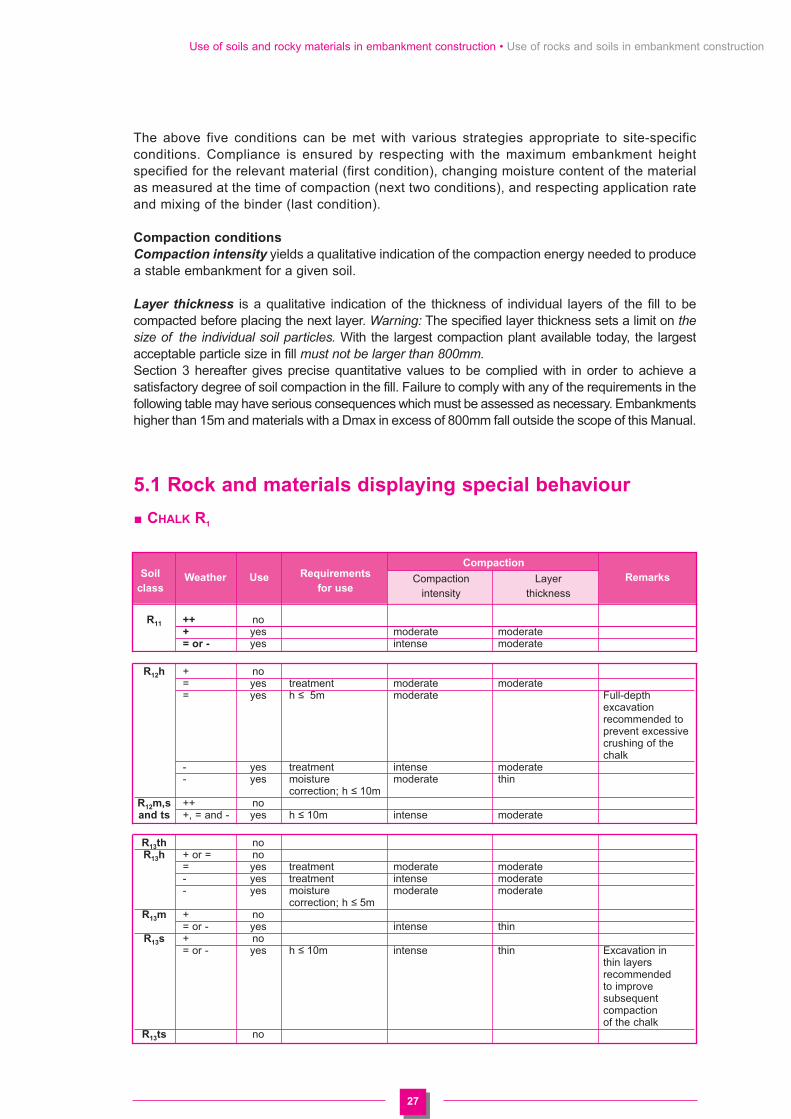
27
Use of soils and rocky materials in embankment construction • Use of rocks and soils in embankment construction
The above five conditions can be met with various strategies appropriate to site-specificconditions. Compliance is ensured by respecting with the maximum embankment heightspecified for the relevant material (first condition), changing moisture content of the materialas measured at the time of compaction (next two conditions), and respecting application rateand mixing of the binder (last condition).
Compaction conditions
Compaction intensity yields a qualitative indication of the compaction energy needed to producea stable embankment for a given soil.
Layer thickness is a qualitative indication of the thickness of individual layers of the fill to becompacted before placing the next layer. Warning: The specified layer thickness sets a limit on thesize of the individual soil particles. With the largest compaction plant available today, the largestacceptable particle size in fill must not be larger than 800mm.Section 3 hereafter gives precise quantitative values to be complied with in order to achieve asatisfactory degree of soil compaction in the fill. Failure to comply with any of the requirements in thefollowing table may have serious consequences which must be assessed as necessary. Embankmentshigher than 15m and materials with a Dmax in excess of 800mm fall outside the scope of this Manual.
5.1 Rock and materials displaying special behaviour
CHALK R1
Soil RequirementsCompaction
classWeather Use
for useCompaction Layer Remarks
intensity thickness
R11 ++ no+ yes moderate moderate= or - yes intense moderate
R12h + no= yes treatment moderate moderate= yes h � 5m moderate Full-depth
excavation recommended to prevent excessive crushing of the chalk
- yes treatment intense moderate- yes moisture moderate thin
correction; h � 10mR12m,s ++ noand ts +, = and - yes h � 10m intense moderate
R13th noR13h + or = no
= yes treatment moderate moderate- yes treatment intense moderate- yes moisture moderate moderate
correction; h � 5mR13m + no
= or - yes intense thinR13s + no
= or - yes h � 10m intense thin Excavation in thin layers recommended to improve subsequent compaction of the chalk
R13ts no

28
Use of soils and rocky materials in embankment construction • Use of rocks and soils in embankment construction
CALCAREOUS ROCKS R2, SILICEOUS ROCKS R
4, IGNEOUS AND METAMORPHIC ROCKS R
6
ARGILLACEOUS ROCKS R3
Soil RequirementsCompaction
classWeather Use
for useCompaction Layer Remarks
intensity thick
R21, ++, +, = yes moderateR41, R61 and -
R22, See soil classes R23, obtained on site R42, (cf. conditions of R43, use below)
R62, R63
Soil RequirementsCompaction
classWeather Use
for useCompaction Layer Remarks
intensity thick
R31 no
R32 ++ no+ yes extra fragmentation intense thin further thought
after extraction ; needed on field h � 10m fragmentation
method and embankment design
= or - yes extra fragmentation intense thin as aboveafter extraction ;h � 5m
= or - yes extra fragmentation intense thin as aboveafter extraction, sprinkling ;h � 10m
R33 ++ no+ yes moderate moderate as above= or - yes intense moderate as above
R34th no
R34h + no= yes treatment with moderate
lime alone= yes extra fragmentation moderate moderate as above
after extraction ;h � 5m
- yes moisture correction ; moderate thin as aboveextra fragmentation after extraction ; h � 10m
- yes treatment with moderatelime alone
R34m ++ no+ yes extra fragmentation moderate moderate as above
after extraction ;h � 10m
= or - yes extra fragmentation intense moderate as aboveafter extraction ;h � 10m
R34s ++ no+ yes moisture correction ; intense thin as above
extra fragmentation after extraction ; h � 5m
= yes sprinkling ; extra intense thin as abovefragmentation after extraction ; h � 5m
- no
R34ts no
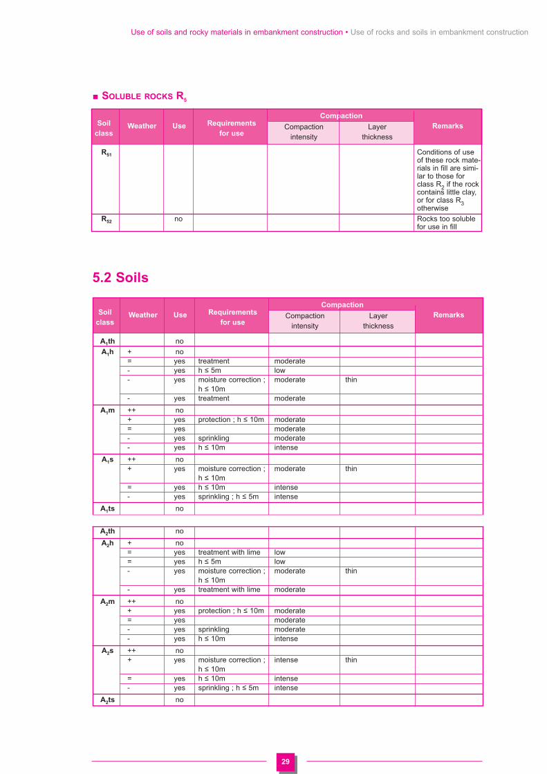
29
Use of soils and rocky materials in embankment construction • Use of rocks and soils in embankment construction
SOLUBLE ROCKS R5
5.2 Soils
Soil RequirementsCompaction
classWeather Use
for useCompaction Layer Remarks
intensity thickness
R51 Conditions of useof these rock mate-rials in fill are simi-lar to those forclass R2 if the rockcontains little clay,or for class R3otherwise
R52 no Rocks too solublefor use in fill
Soil RequirementsCompaction
classWeather Use
for useCompaction Layer Remarks
intensity thickness
A1th no
A1h + no= yes treatment moderate- yes h � 5m low- yes moisture correction ; moderate thin
h � 10m- yes treatment moderate
A1m ++ no+ yes protection ; h � 10m moderate= yes moderate- yes sprinkling moderate- yes h � 10m intense
A1s ++ no+ yes moisture correction ; moderate thin
h � 10m= yes h � 10m intense- yes sprinkling ; h � 5m intense
A1ts no
A2th no
A2h + no= yes treatment with lime low= yes h � 5m low- yes moisture correction ; moderate thin
h � 10m- yes treatment with lime moderate
A2m ++ no+ yes protection ; h � 10m moderate= yes moderate- yes sprinkling moderate- yes h � 10m intense
A2s ++ no+ yes moisture correction ; intense thin
h � 10m= yes h � 10m intense- yes sprinkling ; h � 5m intense
A2ts no

30
Use of soils and rocky materials in embankment construction • Use of rocks and soils in embankment construction
Soil RequirementsCompaction
classWeather Use
for useCompaction Layer Remarks
intensity thickness
A3th no
A3h ++ no+ yes h � 5m low= yes treatment with lime moderate= yes h � 5m low- yes treatment with lime moderate- yes moisture correction ; moderate thin
h � 10m
A3m ++ no+ or = yes h � 10m moderate- yes sprinkling ; h � 10m moderate thin- yes h � 5m intense
A3s ++ no+ yes moisture correction ; intense thin
h � 5m= yes sprinkling ; h � 5m intense thin- yes protection ; sprinkling ; intense thin
h � 5m
A3ts no
A4 no
B1 ++ no+, = or - yes moderate
B2th noB2h + no
= yes treatment moderate
= yes h � 5m low
- yes moisture correction ; moderate thin
h � 10m
- yes moisture correction moderate
and treatment
B2m + no
= yes moderate
- yes intense
- yes sprinkling moderate
B2s ++ no
+ yes moisture correction ; intense thin
h � 10m
= yes h � 10m intense
- yes sprinkling ; h � 10m intense
B2ts no
B3 yes moderate
B4th no
B4h + no
= yes treatment moderate
= yes h � 10m low
- yes moisture correction ; moderate thin
h � 10m
- yes treatment moderate
B4m ++ no
+ yes protection ; h � 10m moderate
= yes moderate
- yes intense
- yes sprinkling moderate

31
Use of soils and rocky materials in embankment construction • Use of rocks and soils in embankment construction
Soil RequirementsCompaction
classWeather Use
for useCompaction Layer Remarks
intensity thickness
B4s ++ no
+ yes moisture correction intense thin
= yes h � 10m intense
- yes sprinkling ; h � 10m intense
B4ts no
B5th noB5th + no
B5h + no
= yes treatment moderate
= yes h � 5m low
- yes moisture correction moderate thin layer
excavation
recommended
- yes moisture correction moderate
and treatment
B5m ++ no
+ yes protection ; h � 10m moderate
= yes moderate
- yes sprinkling moderate
- yes intense
B5s ++ no
+ yes moisture correction ; intense thin
h � 10m
= yes h � 10m intense
- yes protection, sprinkling ; intense
h � 10m
B5ts no
B6th no
B6h + no
= yes treatment with moderate
lime alone
= yes h � 5m low
- yes moisture correction ; moderate thin
h � 10m
- yes treatment with moderate
lime alone
B6m ++ no
+ yes protection ; h � 10m moderate
= yes moderate
- yes h � 10m intense
- yes sprinkling moderate
- yes protection intense
B6s ++ no
+ yes moisture correction ; intense thin
h � 10m
= yes h � 10m intense
- yes sprinkling ; h � 5m intense
- yes sprinkling ; protection ; intense
h � 10m
B6ts no

32
Use of soils and rocky materials in embankment construction • Use of rocks and soils in embankment construction
Soil RequirementsCompaction
classWeather Use
for useCompaction Layer Remarks
intensity thickness
C1A1th no
C1B5th
C1A1h + no
C1B5h
= yes treatment after moderate
removing
particles larger
than 250mm
= or - yes h � 5m low
- yes moisture correction moderate thin
C1A1m ++ no
C1B5m + yes protection ; h � 10m moderate
= yes moderate
- yes intense
- yes sprinkling moderate
C1A1s ++ no
C1B5s + yes h � 5 m intense
+ yes moisture correction ; intense thin
h � 10m
= yes h � 10m intense
- yes sprinkling ; h � 10m intense
C1A1ts no
C1B5ts
C1A2th no
C1A3th
C1B6th
C1A2h ++ no
C1A3h
C1B6h
+ yes protection ; h ≤ 5m low
= yes h ≤ 5m low
= yes treatment with moderate
lime alone after
removing
particles larger
than 250mm
- yes moisture correction ; moderate thin
h � 10m
C1A2m ++ no
C1A3m
C1B6m
+ yes protection ; h � 10m moderate
= yes moderate
- yes intense
- yes sprinkling moderate

33
Use of soils and rocky materials in embankment construction • Use of rocks and soils in embankment construction
Soil RequirementsCompaction
classWeather Use
for useCompaction Layer Remarks
intensity thickness
C1A2s ++ no
C1A3s
C1B6s
+ yes h � 5m intense
+ yes moisture correction ; intense
h � 10m
= yes h � 5m intense
- yes sprinkling: h � 5m intense
C1A2ts no
C1A3ts
C1B6ts
C1A4 no
C1B1 yes moderate
C1B3
C1B2th no
C1B4th
C1B2h + no
C1B4h
= yes treatment moderate
after removing
particles larger
than 250mm
= yes h ≤ 10m low
- yes moisture correction moderate thin
C1B2m ++ no
C1B4m
+ yes protection moderate
+ yes h ≤ 10m moderate
= yes moderate
- yes intense
- yes sprinkling moderate
C1B2s ++ no
C1B4s
+ yes moisture correction intense thin
= yes h ≤ 10m intense
- yes sprinkling ; h � 10m intense
C1B2ts
C1B4ts no

34
Use of soils and rocky materials in embankment construction • Use of rocks and soils in embankment construction
Soil RequirementsCompaction
classWeather Use
for useCompaction Layer Remarks
intensity thickness
C1D1 yes moderate
C1D2
C2A1th no
C2B2th
C2B4th
C2B5th
C2A1h ++ no
C2B2h
C2B4h
C2B5h
+ yes h ≤ 5m moderate
= yes h ≤ 10m moderate
- yes moisture correction moderate moderate
C2A1m ++ no
C2B2m
C2B4m
C2B5m
+ yes moderate
= yes moderate
- yes intense
- yes sprinkling moderate
C2A1s ++ no
C2B2s
C2B4s
C2B5s
+ yes intense moderate
= yes h � 10m intense
- yes sprinkling ; h � 10m intense moderate
C2A1ts no
C2B2ts
C2B4ts
C2B5ts

35
Use of soils and rocky materials in embankment construction • Use of rocks and soils in embankment construction
Soil RequirementsCompaction
classWeather Use
for useCompaction Layer Remarks
intensity thickness
C2A2th no
C2A3th
C2B6th
C2A2h + no
C2A3h
C2B6h
= yes h ≤ 10m low
- yes moisture correction moderate thin
C2A2m ++ no
C2A3m
C2B6m
+ yes h � 10m moderate
= yes moderate
- yes intense
- yes sprinkling moderate
C2A2s ++ no
C2A3s
C2B6s
+ yes moisture correction intense
= yes h � 10m intense
- yes sprinkling ; h � 10m intense moderate
C2A2ts no
C2A3ts
C2B6ts
C2A4 no
C2B1 yes moderate
C2B3
C2D1 yes moderate
C2D2
D1 and D2 yes moderate

36
Use of soils and rocky materials in embankment construction • Compaction of fill
6. Compaction of fill
6.1 Definition of specifications
The GTR method recommended in this Manual has the particular advantage of stating the meansof compaction required of compaction of fill. They are effectively described by specifying the plantand resources to be used, rather than by the standard approach of stipulating results whosedetermination is too uncertain.Where a soil is suitable for the Proctor test (i.e. soils containing less than 30 % particles largerthan 20mm), it has been possible to determine the objectives of densification by compaction ofthe constituent layers of fill, i.e.• dry unit weight averaged over the whole thickness of the compacted layer equal to or greater
than 95 % of the maximum dry unit weight from the standard Proctor test• dry unit weight over the bottom 8 centimetres of the compacted layer equal to or greater than
92 % of the maximum dry unit weight from the standard Proctor test,but this is not true for coarser materials not covered by the Proctor test. With such materials,it is impossible to specify densification objectives or to measure the in-place density achieved by anysimple test.Even with soils suitable for such testing, monitoring the results obtained on the completedembankment or on each layer by measuring the in-place bulk unit weight usually involves manydifficulties such as:- the need for a reference value for the bulk unit weight (generally a percentage of the standard
Proctor density),- the difficulty of measuring the in-place density achieved (mainly because density varies over
the thickness of the compacted layer),- the discrete nature of measurements and their statistical interpretation.Continuous compaction monitoring (section 6-4) has the merit of being based directly on compaction “specifications” which, provided they have a scientific foundation backed up by experience (see tables in section 6-3-2), guarantee the quality of the works at a compactioncost which the contractor can estimate quite closely before commencing the works.The GTR classification system according to type and state describes soil classes such that, within each class, the densification energy needed to obtain a stable fill is roughly the same. In this way, the compaction energy can be set beforehand for each specific job, along with appropriate construction method (see tabulated data in section 5 above).The next step is to classify the compaction plant according to its performance, with reference tothe principles set forth in section 6-2 below.These two items are used in the tables in section 6-3 below in which the required compactionenergy is expressed by two parameters:• maximum thickness (compacted thickness, not bulked thickness) of constituent layers of fill• Q/S ratio in m3 per m2, a measure of the ratio between the compacted soil
volume placed in a given time (say, one day) Q, and the area of fill covered by the compaction machine in the same time S. Volume Q is calculated from the number of round trips by haulage plant of known capacity or beforehand from the estimated geometricalvolume of the embankment to calibrate the haulage plant. Area S is obtained from the effectivewidth of the compaction machine multiplied by the distance covered by the machine, usuallyread from the mileage counter or, better, from a tachograph fitted to the machine. If there arerestrictions on machine use, such as a maximum forward speed, this information appears inthe table in section 6-3.
Controlled trials were the basis for drawing up the tables in section 6-3 below and for checkingthat compliance with:• the stipulated maximum compacted layer thickness, • the requirement that the Q/S ratio effectively obtained on the job is equal to or less than the
stipulated Q/S ratio, and

37
Use of soils and rocky materials in embankment construction • Compaction of fill
• the compaction machine class (ballast, weights and speed of the eccentrics in vibrating rollers)and any type-specific restrictions,
is an a priori assurance of the quality of the work. Since it is the method which is stipulated, theremust be no stipulations on final in-place density obtained (if possible) written into the contract,because of the problem of the accuracy of the reference tests, in order to avoid ambiguities.
6.2 Classification of compaction plant
Refers to French standard NF P 98-736. Basic principles are set forth below.
• Classification and use
The rollers considered have a compactionwidth of 1.30m or more. Classification andconditions of use of small compactingequipment (vibratory rollers, vibrating plates,tampers) is detailed in the TechnicalGuidelines “Trench Backfill and CarriagewayRepair” [SETRA-LCPC Ed. (May 1994)].However, the most efficient vibrating platecompactors are included.
The basic types of compacting plantaddressed are:- pneumatic tyred rollers Pi- smooth vibrating drum rollers Vi- tamping rollers VPi- static tamping rollers SPi- vibrating plate compactors PQi.i is the class number; it increases with compaction efficiency within each type category. Combinationtypes are dealt with in section 6-2-3 below.
6.2.1 Pneumatic tyred rollers (Pi)
• Classification is based on load per wheel CR
P1: CR between 25 and 40 kNP2: CR between 40 and 60 kNP3: CR greater than 60 kN
Pneumatic tyred rollers can be ballasted to obtain the maximum wheel load recommended by themanufacturer. They can usually be ballasted to twice their empty weight. Research into maximum efficiencyindicates that the highest wheel load compatible with trafficability should be used.
Where a roller falls into more than one class, the classification used should be selected with referenceto the effective wheel load used on the job.For best efficiency, it is also recommended that tyres be inflated to the highest pressure compatiblewith trafficability.Maximum forward speed is limited only by consideration of driving safety.
6.2.2 Smooth vibrating drum rollers (Vi)
• Classification and use
Smooth vibrating drum rollers are classified according to parameter (M1/L) �A0 and a minimum A0 value.M1/L7 expressed in kg/cm and A08 in mm lead to the five classes in the following table and the nearbyfigure.
A pneumatic tyred and a vibrating tamping rollers.
7. M1 is the total mass (in kg) acting on the full width of the vibrating or static drum. L is the width (in cm) of the vibrating or static drum
8. A0 is the theoretical empty amplitude calculated as A0 = 1000 (me/M0) in which me is the eccentric moment (in mkg) and M0 is the
mass (in kg)of the vibrating part excited by the eccentric.

38
Use of soils and rocky materials in embankment construction • Compaction of fill
CL
AS
SIF
ICA
TIO
N O
F V
IBR
AT
ING
RO
LL
ER
SS
ing
le d
rum

39
Use of soils and rocky materials in embankment construction • Compaction of fill
A0 can be tested by the “cushion” method described in French standard NF P 98-761 “VerificationTest of Moment of Vibrating Roller Eccentrics.”Many vibrating rollers have more than one empty nominal amplitude value (by changingeccentric moment) and/or, less frequently, can be ballasted. This may cause machines toappear in more than one class according to their A0 and/or M1/L value.
Vibrating rollers are assumed to operateat the maximum frequency set by themanufacturer for a given eccentric system.
Except for classes V1 and V2, a range offorward speeds is assumed, with a bearingon compaction practice (Appendix 4.1.2).However, while high speeds are attractivein that they speed up work rates, this isonly permitted with machines fitted witha speedometer on the instrument paneland a recording system for monitoringpurposes.
• Single and tandem drum rollers
The two most common types are singledrum designated VMi and tandems, VTi(Vi is the efficiency class defined above).
- Category VMi contains all singlevibrating drum types, twin drum types(two drums on the same axle) andtandems in which only one drumvibrates. Tables (e, Q/S) are directlyapplicable to these types.
- Category VTi is for tandems with twovibrating drums.
In most cases, the efficiency class is thesame for both the front and rear drums.Compared to single drum types, the Q/Sand number of load applications are thesame, but the number of passes ishalved.
Empty amplitude A0 can be measured with a vibrographwhile vibrating the roller on air-filled cushions (Frenchstandard NF P 98-761).
Class VM4 single smooth vibrating drum roller.
V1 (M1/L) x �A0 { between 15 and 25 and A0 � 0.6{ greater than 25 and A0 between 0.6 and 0.8
V2 (M1/L) x �A0 { between 25 and 40 and A0 � 0.8{ greater than 40 and A0 between 0.8 and 1.0
V3 (M1/L) x �A0 { between 40 and 55 and A0 � 1.0{ greater than 55 and A0 between 1.0 and 1.3
V4 (M1/L) x �A0 { between 55 and 70 and A0 � 1.3{ greater than 70 and A0 between 1.3 and 1.6
V5 (M1/L) x �A0 { greater than 70 and A0 � 1.6

40
Use of soils and rocky materials in embankment construction • Compaction of fill
6.2.3 Vibrating Tamping rollers (VPi)
Tamping rollers are mostly derived from smooth vibrating drum rollers discussed in section 6-2-2 above, and are classified on the same criteria.
Compaction methods only differ from smooth drum rollers in class VP3 and beyond. They seekto extract the most benefit from both vibration and the tamping feet. The tamping rollers in thecompaction tables are single drum types designated VPi in French standard NF P 98-736.
6.2.4 Static Tamping rollers (SPi)
Static tamping rollers are classified according to the average static load per unit width of drum(s)with tamping feet.
SP1: M1/L between 30 and 60 kg/cmSP2: M1/L greater than 60 kg/cm
but less than 90 kg/cm
Machines with provision of ballasting are classified according to their configuration on site.
They should be driven at maximum allowedspeed and final compaction should be doneat 10-12 kph. The first passes shouldgenerally be made at distinctly slowerspeeds but never less than 2-3 kph.
The time that rollers fitted with a bladespend as bulldozers and graders is notconsidered compaction time.
If average speed recorded on site (whichshould not be less than 6 kph) is less thanthe average shown in the compaction tables,this fact must be considered to recalculatethe rate.
Tandem rollers frequently have the same Q/S and number of load applications as single drumtypes (values in table). The number of passes must be halved.
6.2.5 Vibrating plate compactors (PQi)
All plate compactors are classified as PQ1 to PQ4 in the Technical Guidelines on Trench Backfilland Carriageway Repair. [SETRA - LCPC Ed. /May 1994]
They are classified on the basis of the static pressure under the plate Mg/S in kPa (Mg is theweight of the plate).
The smallest plates PQ1 and PQ2 are ignored. Those included are
PQ3: Mg/S between 10 and 15 kPaPQ4: Mg/S greater than 15 kPa.
S is the contact area between plate and soil, not the overall area. S varies on models which canbe fitted with extensions and this may alter the classification.
SP1 static tamping roller. When used as a grader as inthe photograph, it is not considered.

41
Use of soils and rocky materials in embankment construction • Compaction of fill
6.3 Compaction specifications
6.3.1 Use of tables - Examples of application
* Classes Pi, V1, V2, VPi, SPi and PQi (single column)
Example: B1 soil in embankment (quality q4)
Same value (in m) for all thicknesses
Actual compacted thickness e < e (in m)V is max speed for vibratory plant, average speed forother plant (in kph)
Number of load applications: rounded up from actualthickness/(Q/S) given for e of the tableIf e = 0.30, then N = 5
Rate per metre widthQ/L = 1000 x V x (Q/S)Practical rate of compacting operations with an efficiencyratio k (between 0.5 et 0.75)Qpract = k x (Q/L x L x (N/n)If k = 0.6 L = 2m N/n = 1, thenQpract = 360 m3/hr
* Classes V3 to V5 (double columns: possible envelope)
Example: B1 soil in embankment
Same value for all combinations of thickness and speed
Right column: choice of low V 2.0 kph to maximise e (0.80m)Left column: max rate with high V limited to 5 kph maxand e set at 0.30m
Same design rules as before in each column
It can be seen that a higher forward speed is necessarily associated with a lesser layer thicknessbecause of the steeper density gradient in the layer. Providing these conditions are complied with,the compaction rate is still higher.It is of course unacceptable to mix values from both columns (greatest thickness and highest speed).
Method ClassP1
Code 2 Q/S 0.060
Applicable code e 0.35comes from soil V 5.0use tables (basedon moisture
N 6content and weather)
Q/L 300
Method ClassV3
Code 2 Q/S 0.135
e 0.30 0.80
V 5 2
N 3 6
Q/L 675 270

42
Use of soils and rocky materials in embankment construction • Compaction of fill
If the nominal thickness e for the job (ejob) falls between the above two values, optimumcompaction conditions can be calculated as follows:
- average vibrating roller speed calculated from V x e = constant (values considered are takenfrom the right hand column: V min and e max)
V =V x eejob
- Q/L calculated withQ/L = 1000 x V x Q/S
- N is always taken as equal to ejob/ (Q/S)
The values calculated in this way are then used as requirements as if they came directly fromthe tables.
In the above example, if the planned layer thickness for the job is 0.50m, V is defined as
V = (0.80 x 2)/0.5 = 3.2 rounded off to 3
N = 0.5 / 0.135 = 3.7 rounded off to 4
Q/L = 1000 x 3 x 0.135 = 405
* Case of different classes of plant working on same fill
Compaction energy applied by a machine is taken as
Ci = [Q/S]table / [Q/S]i
in which [Q/S]table is the Q/S value prescribed for machine i for the soil to attain a satisfactorydegree of compaction[Q/S]i is the Q/S value obtained by machine i in the time considered.
The requirement for obtaining the compaction with n compacting plants is:
i = n
C(i � 1)i = 1
Method V3
Code 2 Q/S 0.135
e 0.50
V 3
N 4
Q/L 405

43
Use of soils and rocky materials in embankment construction • Compaction of fill
A1,
C1A
1(*
)
6.3
.2 C
om
pacti
on
ta
ble
s
Co
mp
acti
on
ta
ble
s f
or
use o
fm
ate
rials
in
fill
Ma
ch
ine
Me
tho
dP
1P
2P
3V
1V
2V
3V
4V
5V
P1
VP
2V
P3
VP
4V
P5
SP
1S
P2
PQ
3P
Q4
Q/S
0.08
00.
120
0.18
00.
055
0.08
50.
125
0.16
50.
205
0.05
50.
085
0.16
50.
205
0.26
50.
070
0.10
00.
065
Low
e0.
300.
450.
600.
250.
350.
300.
500.
350.
650.
400.
800.
250.
300.
300.
350.
400.
250.
400.
20co
mpa
ctio
n (1
)(1
)(1
)(1
)(1
)(1
)(2
)(2
)(2
)(2
)(2
)(2
)(2
)0
(1)
ener
gyV
5.0
5.0
5.0
2.0
2.5
4.0
2.5
5.0
2.5
5.0
2.5
2.0
3.0
4.0
5.0
5.0
8.0
8.0
1.0
Cod
e 3
N4
44
55
34
34
24
54
22
24
43
Q/L
400
600
900
110
215
500
315
825
415
1025
515
110
255
660
1025
1325
560
800
65
Q/S
0.04
50.
065
0.09
50.
040
0.06
50.
085
0.10
00.
040
0.08
50.
100
0.13
00.
040
0.07
0
Mod
erat
e e
0.25
0.35
0.45
0.25
0.30
0.40
0.30
0.50
0.30
0.60
0.25
0.30
0.30
0.30
0.20
0.30
com
pact
ion
00
(2)
(2)
(2)
(2)
(2)
(2)
00
ener
gyV
5.0
5.0
5.0
2.0
2.5
2.0
3.5
2.0
4.0
2.0
2.0
2.5
3.5
4.0
8.0
8.0
Cod
e 2
N6
65
75
74
63
67
43
35
5
Q/L
225
325
475
8016
513
030
017
040
020
080
215
350
520
320
560
Q/S
0.03
50.
050
0.02
50.
040
0.05
00.
065
0.02
50.
050
0.06
50.
085
0.03
5
Hig
h e
0.20
0.30
0.20
0.30
0.30
0.40
0.30
0.45
0.20
0.30
0.30
0.30
0.25
com
pact
ion
00
00
00
ener
gyV
5.0
5.0
2.0
2.0
2.5
2.0
3.0
2.0
2.0
2.0
2.5
3.0
8.0
Cod
e 1
N6
68
86
85
78
65
48
Q/L
175
250
5080
125
100
195
130
5010
016
525
528
0
Q/S
(m)
(*)
Req
uire
d D
max
< 2
/3rd
s co
mpa
cted
laye
r th
ickn
ess
e(m
)(1
) C
heck
tra
ffica
bilit
y fo
r m
achi
neV
(km
/h)
(2)
Pro
vide
for
rem
ovin
g ru
ts w
hen
ther
e is
a r
isk
of r
ain
at c
lose
of
N-
wor
king
day
(pl
ane
off
top
few
cen
timet
res
or u
se a
noth
er t
ype
of r
olle
rQ
/L(m
3/h.
m)
if it
prod
uces
the
des
ired
resu
lt)0
Mac
hine
typ
e un
suita
ble

44
Use of soils and rocky materials in embankment construction • Compaction of fill
A2,
C1
A2
(*)
Co
mp
acti
on
ta
ble
s f
or
use o
fm
ate
rials
in
fill
Ma
ch
ine
Me
tho
dP
1P
2P
3V
1V
2V
3V
4V
5V
P1
VP
2V
P3
VP
4V
P5
SP
1S
P2
PQ
3P
Q4
Q/S
0.05
00.
080
0.12
00.
040
0.06
00.
090
0.12
00.
145
0.04
00.
060
0.12
00.
145
0.19
00.
065
0.10
0
Low
e0.
250.
350.
450.
200.
300.
300.
350.
300.
450.
300.
600.
200.
300.
300.
300.
300.
250.
40co
mpa
ctio
n (2
)(2
)(2
)(2
)(2
)(2
)(2
)0
0
ener
gyV
5.0
5.0
5.0
2.0
2.0
3.0
2.5
4.0
2.5
5.0
2.5
2.0
2.0
3.0
4.0
5.0
8.0
8.0
Cod
e 3
N5
54
55
44
34
35
55
33
24
4
Q/L
250
400
600
8012
027
022
548
030
072
536
580
120
360
580
950
520
800
Q/S
0.03
00.
050
0.07
00.
035
0.05
00.
065
0.08
00.
035
0.06
50.
080
0.10
50.
035
0.06
0
Mod
erat
e e
0.20
0.25
0.35
0.20
0.30
0.30
0.40
0.30
0.45
0.20
0.30
0.30
0.30
0.20
0.30
com
pact
ion
00
(2)
(2)
(2)
(2)
(2)
(2)
00
ener
gyV
5.0
5.0
5.0
2.0
2.0
2.5
2.0
3.0
2.0
2.0
2.0
2.5
3.0
8.0
8.0
Cod
e 2
N7
55
66
57
46
65
43
65
Q/L
150
250
350
7010
016
513
024
016
070
130
200
315
280
480
Q/S
0.03
00.
040
0.03
50.
045
0.05
50.
045
0.05
50.
070
0.03
0
Hig
h e
0.20
0.30
0.25
0.35
0.30
0.40
0.25
0.30
0.30
0.20
com
pact
ion
00
00
00
00
ener
gyV
5.0
5.0
2.0
2.0
2.5
2.0
2.0
2.0
2.5
8,0
Cod
e 1
N7
88
86
86
65
7
Q/L
150
200
7090
140
110
9011
017
524
0
Q/S
(m)
(*)
Req
uire
d D
max
< 2
/3rd
s co
mpa
cted
laye
r th
ickn
ess
e(m
)(1
) C
heck
tra
ffica
bilit
y fo
r m
achi
neV
(km
/h)
(2)
Pro
vide
for
rem
ovin
g ru
ts w
hen
ther
e is
a r
isk
of r
ain
at c
lose
of
N-
wor
king
day
(pl
ane
off
top
few
cen
timet
res
or u
se a
noth
er t
ype
of r
olle
rQ
/L(m
3 /h.m
)if
it pr
oduc
es t
he d
esire
d re
sult)
0M
achi
ne t
ype
unsu
itabl
e

45
Use of soils and rocky materials in embankment construction • Compaction of fill
A3,
C1A
3(*
)C
om
pacti
on
ta
ble
s f
or
use o
fm
ate
rials
in
fill
Ma
ch
ine
Me
tho
dP
1P
2P
3V
1V
2V
3V
4V
5V
P1
VP
2V
P3
VP
4V
P5
SP
1S
P2
PQ
3P
Q4
Q/S
0.02
00.
040
0.06
00.
040
0.05
50.
070
0.08
50.
040
0.07
00.
085
0.11
00.
040
0.07
0
Low
e0.
200.
250.
350.
200.
250.
300.
350.
300.
450.
200.
250.
300.
300.
250.
35
com
pact
ion
00
(2)
(2)
(2)
(2)
(2)
(2)
00
ener
gyV
5.0
5.0
5.0
2.0
2.0
2.5
2.0
3.0
2.0
2.0
2.0
2.5
3.0
8.0
8.0
Cod
e 3
N10
76
55
55
46
54
44
75
Q/L
100
200
300
8011
017
514
025
517
080
140
215
330
320
560
Q/S
0.03
00.
050
0.03
50.
045
0.05
50.
045
0.05
50.
070
0.02
50.
045
Mod
erat
e e
0.20
0.30
0.20
0.25
0.30
0.20
0.25
0.30
0.20
0.25
com
pact
ion
00
00
00
0
ener
gyV
5.0
5.0
2.0
2.0
2.0
2.0
2.0
2.0
8.0
8.0
Cod
e 2
N7
66
65
55
86
Q/L
150
250
7090
110
9011
014
020
036
0
Q/S
0.03
00.
030
0.03
50.
035
0.04
50.
025
Hig
h e
0.20
0.20
0.25
0.20
0.25
0.20
com
pact
ion
00
00
00
00
00
00
ener
gyV
5.0
2.0
2.0
2.0
2.0
8.0
Cod
e 1
N7
78
66
8
Q/L
150
6070
7090
200
Q/S
(m)
(*)
Req
uire
d D
max
< 2
/3rd
s co
mpa
cted
laye
r th
ickn
ess
e(m
)V
(km
/h)
(2)
Pro
vide
for
rem
ovin
g ru
ts w
hen
ther
e is
a r
isk
of r
ain
at c
lose
of
N-
wor
king
day
(pl
ane
off
top
few
cen
timet
res
or u
se a
noth
er t
ype
of r
olle
rQ
/L(m
3 /h.m
)if
it pr
oduc
es t
he d
esire
d re
sult)
0M
achi
ne t
ype
unsu
itabl
e

46
Use of soils and rocky materials in embankment construction • Compaction of fill
B1,
D1,
C1B
1(*
),
C1D
1(*
)
B3,
D2,
C1B
3(*
)
C1D
2(*
)
Co
mp
acti
on
ta
ble
s f
or
use o
fm
ate
rials
in
fill
Co
mp
acti
on
ta
ble
s f
or
use o
fm
ate
rials
in
fill
Ma
ch
ine
Me
tho
dP
1P
2P
3V
1V
2V
3V
4V
5V
P1
VP
2V
P3
VP
4V
P5
SP
1S
P2
PQ
3P
Q4
Q/S
0.06
00.
090
0.12
00.
055
0.08
50.
135
0.18
00.
225
0.07
50.
100
Mod
erat
ee
0.35
0.45
0.65
0.35
0.50
0.30
0.80
0.45
1.10
0.55
1.35
0.45
0.60
com
pact
ion
(1)
(1)
(1)
(1)
00
00
00
0
ener
gyV
5.0
5.0
5.0
2.0
2.0
5.0
2.0
5.0
2.0
5.0
2.0
1.0
1.0
Cod
e 2
N6
56
76
36
37
36
66
Q/L
300
450
600
110
170
675
270
900
360
1125
450
7510
0
Ma
ch
ine
Me
tho
dP
1P
2P
3V
1V
2V
3V
4V
5V
P1
VP
2V
P3
VP
4V
P5
SP
1S
P2
PQ
3P
Q4
Q/S
0.05
50.
080
0.11
50.
050
0.08
00.
120
0.16
50.
200
0.65
0.09
0
Mod
erat
ee
0.30
0.40
0.60
0.30
0.50
0.30
0.75
0.40
1.00
0.50
1.20
0.40
0.55
com
pact
ion
00
00
00
0
ener
gyV
5.0
5.0
5.0
2.0
2.0
5.0
2.0
5.0
2.0
5.0
2.0
1.0
1,0
Cod
e 2
N6
56
67
37
37
36
66
Q/L
275
400
575
100
160
600
240
825
330
1000
400
6590
Q/S
(m)
(*)
Req
uire
d D
max
< 2
/3rd
s co
mpa
cted
laye
r th
ickn
ess
e(m
)(1
) C
heck
rol
ler
traf
ficab
ility
V(k
m/h
)N
-Q
/L(m
3 /h.m
)0
Mac
hine
typ
e un
suita
ble

47
Use of soils and rocky materials in embankment construction • Compaction of fill
Q/S
(m)
(*)
Req
uire
d D
max
< 2
/3rd
s co
mpa
cted
laye
r th
ickn
ess
e(m
)V
(km
/h)
N-
Q/L
(m3 /h
.m)
0M
achi
ne t
ype
unsu
itabl
e
B2,
B4,
C1B
2(*
),
C1B
4(*
)C
om
pacti
on
ta
ble
s f
or
use o
fm
ate
rials
in
fill
Ma
ch
ine
Me
tho
dP
1P
2P
3V
1V
2V
3V
4V
5V
P1
VP
2V
P3
VP
4V
P5
SP
1S
P2
PQ
3P
Q4
Q/S
0.10
00.
150
0.25
00.
085
0.13
50.
205
0.27
50.
340
0.15
00.
200
Low
e0.
300.
450.
650.
350.
550.
400.
850.
551.
100.
701.
350.
300.
40
com
pact
ion
00
00
00
0
ener
gyV
5.0
5.0
5.0
2.5
2.5
5.0
2.5
5.0
2.5
5.0
2.5
1.0
1.0
Cod
e 3
N3
33
55
25
24
34
22
Q/L
500
750
1250
215
340
1025
515
1375
690
1700
850
150
200
Q/S
0.06
00.
090
0.13
00.
045
0.07
00.
105
0.14
00.
175
0.05
00.
090
Mod
erat
e e
0.25
0.35
0.50
0.25
0.40
0.30
0.65
0.35
0.85
0.40
1.05
0.25
0.35
com
pact
ion
00
00
00
0
ener
gyV
5.0
5.0
5.0
2.0
2.0
4.5
2.0
5.0
2.0
5.0
2.0
1.0
1.0
Cod
e 2
N5
44
66
37
37
36
54
Q/L
300
450
650
9014
047
521
070
028
087
535
050
90
Q/S
0.03
00.
045
0.07
00.
025
0.03
50.
055
0.07
50.
095
0.02
00.
050
Hig
h e
0.20
0.25
0.40
0.20
0.30
0.30
0.45
0.30
0.55
0.30
0.70
0.20
0.30
com
pact
ion
00
00
00
0
ener
gyV
5.0
5.0
5.0
2.0
2.0
3.0
2.0
4.0
2.0
4.5
2.0
1.0
1.0
Cod
e 1
N7
66
89
69
48
48
106
Q/L
150
225
350
5070
165
110
300
150
430
190
2050

48
Use of soils and rocky materials in embankment construction • Compaction of fill
Co
mp
acti
on
ta
ble
s f
or
use o
fm
ate
rials
in
fill
B5,
C1B
5(*
)
Q/S
(m)
(*)
Req
uire
d D
max
< 2
/3rd
s co
mpa
cted
laye
r th
ickn
ess
e(m
)V
(km
/h)
N-
Q/L
(m3 /h
.m)
0M
achi
ne t
ype
unsu
itabl
e
Ma
ch
ine
Me
tho
dP
1P
2P
3V
1V
2V
3V
4V
5V
P1
VP
2V
P3
VP
4V
P5
SP
1S
P2
PQ
3P
Q4
Q/S
0.09
00.
130
0.20
00.
060
0.09
50.
145
0.19
50.
235
0.06
50.
100
Low
e0.
300.
450.
600.
300.
400.
300.
600.
400.
800.
450.
950.
200.
30
com
pact
ion
00
00
00
0
ener
gyV
5.0
5.0
5.0
2.0
2.5
5.0
2.5
5.0
2.5
5.0
2.5
1.0
1.0
Cod
e 3
N4
43
55
35
35
24
33
Q/L
450
650
1000
120
240
725
365
975
490
1175
590
6510
0
Q/S
0.05
00.
080
0.12
00.
030
0.05
00.
075
0.10
00.
120
0.05
0
Mod
erat
e e
0.25
0.35
0.45
0.20
0.30
0.30
0.45
0.30
0.60
0.30
0.75
0.20
com
pact
ion
00
00
00
00
ener
gyV
5.0
5.0
5.0
2.0
2.0
3.0
2.0
4.0
2.0
5.0
2.0
1.0
Cod
e 2
N5
54
76
46
36
37
4
Q/L
250
400
600
6010
022
515
040
020
060
024
050
Q/S
0.04
00.
060
0.03
00.
040
0.05
50.
065
Hig
h e
0.20
0.30
0.20
0.30
0.35
0.40
0.30
0.50
com
pact
ion
00
00
00
00
00
0
ener
gyV
5.0
5.0
2.0
2.0
2.5
2.0
3.5
2.0
Cod
e 1
N5
57
87
85
8
Q/L
200
300
6080
140
110
230
130

49
Use of soils and rocky materials in embankment construction • Compaction of fill
B6,
C1B
6(*
)C
om
pacti
on
ta
ble
s f
or
use o
fm
ate
rials
in
fill
Ma
ch
ine
Me
tho
dP
1P
2P
3V
1V
2V
3V
4V
5V
P1
VP
2V
P3
VP
4V
P5
SP
1S
P2
PQ
3P
Q4
Q/S
0.04
50.
075
0.12
00.
045
0.07
50.
110
0.14
50.
180
0.04
50.
075
0.14
50.
180
0.23
50.
080
0.12
00.
050
0.08
5
Low
e0.
200.
300.
450.
250.
300.
300.
450.
300.
600.
350.
700.
250.
300.
300.
300.
350.
250.
400.
200.
25
com
pact
ion
(2)
(2)
(2)
(2)
(2)
(2)
(2)
ener
gyV
5.0
5.0
5.0
2.0
2.5
3.5
2.5
5.0
2.5
5.0
2.5
2.0
2.5
3.5
5.0
5.0
8.0
8.0
1.0
1.0
Cod
e 3
N5
44
64
35
35
24
64
32
24
44
3
Q/L
225
375
600
9019
038
527
572
536
590
045
090
190
510
900
1175
640
960
5085
Q/S
0.03
00.
050
0.07
50.
040
0.06
00.
080
0.09
50.
040
0.08
00.
095
0.12
50.
050
0.07
5
Mod
erat
e e
0.20
0.25
0.35
0.25
0.30
0.35
0.30
0.50
0.30
0.60
0.25
0.30
0.30
0.30
0.20
0.30
com
pact
ion
00
(2)
(2)
(2)
(2)
(2)
(2)
00
ener
gyV
5.0
5.0
5.0
2.0
2.5
2.0
3.0
2.0
4.0
2.0
2.0
2.5
3.0
4.0
8.0
8.0
Cod
e 2
N7
55
75
64
74
77
44
34
4
Q/L
150
250
375
8015
012
024
016
038
019
080
200
285
500
400
600
Q/S
0.03
00.
040
0.02
50.
035
0.04
50.
055
0.02
50.
045
0.05
50.
070
0.03
5
Hig
h e
0.20
0.25
0.20
0.25
0.30
0.35
0.30
0.40
0.20
0.25
0.30
0.30
0.20
com
pact
ion
00
00
00
0
ener
gyV
5.0
5.0
2.0
2.0
2.5
2.0
3.0
2.0
2.0
2.0
2.5
3.0
8.0
Cod
e 1
N7
78
87
86
88
66
56
Q/L
150
200
5070
115
9016
511
050
9014
021
028
0
Q/S
(m)
(*)
Req
uire
d D
max
< 2
/3rd
s co
mpa
cted
laye
r th
ickn
ess
e(m
)(2
) P
rovi
de f
or r
emov
ing
ruts
whe
n th
ere
is a
ris
k of
rai
n at
clo
se o
fV
(km
/h)
wor
king
day
(pl
ane
off
top
few
cen
timet
res
or u
se a
noth
er t
ype
of r
olle
r N
-f
it pr
oduc
es t
he d
esire
d re
sult)
Q/L
(m3 /h
.m)
0M
achi
ne t
ype
unsu
itabl
e

50
Use of soils and rocky materials in embankment construction • Compaction of fill
Co
mp
acti
on
ta
ble
s f
or
use o
fm
ate
rials
in
fill
C2A
1(*
),C
2B
2 (*)
,
C2 B
4 (*)
,C
2B
5 (*)
Ma
ch
ine
Me
tho
dP
1P
2P
3V
1V
2V
3V
4V
5V
P1
VP
2V
P3
VP
4V
P5
SP
1S
P2
PQ
3P
Q4
(**)
(**)
(**)
(**)
(**)
(**)
(**)
Q/S
0.07
00.
100
0.15
00.
050
0.08
00.
120
0.16
00.
190
0.05
00.
080
0.16
00.
190
0.24
50.
070
0.10
00.
065
Low
e0.
250.
350.
500.
250.
300.
300.
500.
300.
650.
400.
750.
250.
300.
300.
300.
400.
250.
400.
25
com
pact
ion
(2)
(2)
(2)
(2)
(2)
(2)
(2)
0
ener
gyV
5.0
5.0
5.0
2.0
2.5
4.0
2.5
5.0
2.5
5.0
2.5
2.0
2.5
4.0
5.0
5.0
8.0
8.0
1.0
Cod
e 3
N4
44
54
35
25
34
54
22
24
44
Q/L
350
500
750
100
200
480
300
800
400
950
475
100
200
640
950
1225
560
800
65
Q/S
0.04
00.
060
0.09
00.
040
0.06
00.
080
0.10
00.
040
0.08
00.
100
0.13
00.
050
Mod
erat
e e
0.20
0.30
0.40
0.25
0.30
0.35
0.30
0.50
0.30
0.60
0.25
0.30
0.30
0.30
0.25
0.20
com
pact
ion
00
(2)
(2)
(2)
(2)
0(2
)0
ener
gyV
5.0
5.0
5.0
2.0
2.5
2.0
3.0
2.0
4.0
2.0
2.0
2.5
3.0
4.0
8.0
1.0
Cod
e 2
N5
55
75
64
73
67
43
35
5
Q/L
200
300
450
8015
012
024
016
040
020
080
200
300
520
400
40
Q/S
0.03
00.
050
0.02
50.
040
0.05
00.
065
0.02
50.
050
0.06
50.
085
Hig
h e
0.20
0.30
0.20
0.30
0.30
0.40
0.30
0.45
0.20
0.30
0.30
0.30
com
pact
ion
00
00
00
0
ener
gyV
5.0
5.0
2.0
2.0
2.5
2.0
3.0
2.0
2.0
2.0
2.5
3.0
Cod
e 1
N7
68
86
85
78
65
4
Q/L
150
250
5080
125
100
195
130
5010
016
525
5
Q/S
(m)
(*)
Req
uire
d D
max
< 2
/3rd
s co
mpa
cted
laye
r th
ickn
ess
e(m
)(*
*)O
nly
C2(
A1)
soi
ls c
an b
e co
mpa
cted
with
tam
ping
rol
lers
V(k
m/h
)(2
) P
rovi
de f
or r
emov
ing
ruts
whe
n th
ere
is a
ris
k of
rai
n at
clo
se
N-
of w
orki
ng d
ay (
plan
e of
f to
p fe
w c
entim
etre
s or
use
ano
ther
typ
e of
rol
ler
Q
/L(m
3 /h.m
)if
it pr
oduc
es t
he d
esire
d re
sult)
0 M
achi
ne t
ype
unsu
itabl
e

51
Use of soils and rocky materials in embankment construction • Compaction of fill
C2A
2(*
),C
2A
3 (*)
,C
2 B
6 (*)
Co
mp
acti
on
ta
ble
s f
or
use o
fm
ate
rials
in
fill
Ma
ch
ine
Me
tho
dP
1P
2P
3V
1V
2V
3V
4V
5V
P1
VP
2V
P3
VP
4V
P5
SP
1S
P2
PQ
3P
Q4
Q/S
0.05
00.
075
0.10
00.
035
0.05
50.
080
0.10
50.
130
0.03
50.
055
0.10
50.
130
0.17
00.
050
0.09
00.
050
Low
e0.
200.
300.
400.
200.
250.
300.
400.
300.
550.
300.
650.
200.
250.
300.
300.
300.
200.
350.
25
com
pact
ion
(2)
(2)
(2)
(2)
(2)
(2)
(2)
0
ener
gyV
5.0
5.0
5.0
2.0
2.0
2.5
2.0
3.5
2.0
4.5
2.0
2.0
2.0
2.5
3.5
4.5
8.0
8.0
1.0
Cod
e 3
N4
44
65
45
36
35
65
33
24
45
Q/L
250
375
500
7011
020
016
037
021
058
526
070
110
265
455
765
400
720
50
Q/S
0.03
00.
045
0.07
00.
035
0.05
50.
070
0.08
50.
035
0.07
00.
085
0.11
00.
045
0.03
5
Mod
erat
e e
0.20
0.25
0.30
0.20
0.30
0.30
0.40
0.30
0.50
0.20
0.30
0.30
0.30
0.25
0.20
com
pact
ion
00
(2)
(2)
(2)
(2)
0(2
)0
ener
gyV
5.0
5.0
5.0
2.0
2.0
3.0
2.0
3.5
2.0
2.0
2.0
3.0
3.5
8.0
1.0
Cod
e 2
N7
65
66
56
46
65
43
66
Q/L
150
225
350
7011
021
014
030
017
070
140
255
385
360
35
Q/S
0.02
50.
040
0.02
50.
035
0.04
50.
055
0.02
50.
045
0.05
50.
070
Hig
h e
0.20
0.25
0.20
0.25
0.30
0.35
0.30
0.40
0.20
0.25
0.30
0.30
com
pact
ion
00
00
00
0
ener
gyV
5.0
5.0
2.0
2.0
2.5
2.0
3.0
2.0
2.0
2.0
2.5
3.0
Cod
e 1
N8
78
87
86
88
66
5
Q/L
125
200
5070
115
9016
511
050
9014
021
0
Q/S
(m)
(*)
Req
uire
d D
max
< 2
/3rd
s co
mpa
cted
laye
r th
ickn
ess
e(m
)(2
)P
rovi
de f
or r
emov
ing
ruts
whe
n th
ere
is a
ris
k of
rai
n at
clo
seV
(km
/h)
of w
orki
ng d
ay (
plan
e of
f to
p fe
w c
entim
etre
s or
use
ano
ther
typ
e of
rol
ler
N-
if it
prod
uces
the
des
ired
resu
lt)Q
/L(m
3 /h.m
)0
Mac
hine
typ
e un
suita
ble

52
Use of soils and rocky materials in embankment construction • Compaction of fill
Co
mp
acti
on
ta
ble
s f
or
use o
fm
ate
rials
in
fill
Co
mp
acti
on
ta
ble
s f
or
use o
fm
ate
rials
in
fill
C2D
1(*
),C
2D
2 (*)
,
C2 B
1 (*)
,C
2 B
3
Q/S
(m)
(*)
Req
uire
d D
max
< 2
/3rd
s co
mpa
cted
laye
r th
ickn
ess
e(m
)V
(km
/h)
N-
Q/L
(m3 /h
.m)
0M
achi
ne t
ype
unsu
itabl
e
R1
(*)
Ma
ch
ine
Me
tho
dP
1P
2P
3V
1V
2V
3V
4V
5V
P1
VP
2V
P3
VP
4V
P5
SP
1S
P2
PQ
3P
Q4
Q/S
0.04
50.
070
0.10
00.
035
0.05
50.
085
0.11
50.
140
0.05
00.
065
Mod
erat
ee
0.25
0.35
0.50
0.20
0.35
0.30
0.50
0.30
0.70
0.35
0.85
0.30
0.40
com
pact
ion
00
00
00
0
ener
gyV
5.0
5.0
5.0
2.0
2.0
3.5
2.0
4.5
2.0
5.0
2.0
1.0
1.0
Cod
e 3
N6
55
67
46
37
37
66
Q/L
225
350
500
7011
030
017
052
023
070
028
050
65
Ma
ch
ine
Me
tho
dP
1P
2P
3V
1V
2V
3V
4V
5V
P1
VP
2V
P3
VP
4V
P5
SP
1S
P2
PQ
3P
Q4
Q/S
0.05
00.
085
0.05
00.
075
0.10
00.
120
0.05
00.
100
0.12
00.
155
0.05
00.
080
0.04
00.
050
Mod
erat
ee
0.30
0.40
0.25
0.30
0.40
0.30
0.50
0.30
0.60
0.25
0.30
0.30
0.30
0.30
0.35
0.25
0.30
com
pact
ion
00
0
ener
gyV
5.0
5.0
2.0
2.5
2.0
3.5
2.0
4.0
2.0
2.0
2.5
3.5
4.0
8.0
8.0
1.0
1.0
Cod
e 3
N6
55
46
35
35
53
32
65
66
Q/L
250
425
100
190
150
350
200
480
240
100
250
420
620
400
640
4050
Q/S
0.03
00.
050
0.03
00.
045
0.06
00.
070
0.03
00.
060
0.07
00.
090
0.03
00.
050
0.02
5
Hig
h e
0.25
0.35
0.25
0.30
0.35
0.30
0.45
0.30
0.60
0.25
0.30
0.30
0.30
0.25
0.30
0.20
com
pact
ion
00
00
ener
gyV
5.0
5.0
2.0
2.5
2.0
3.0
2.0
4.0
2.0
2.0
2.5
3.0
4.0
8.0
8.0
1.0
Cod
e 2
N9
79
78
58
59
95
54
96
8
Q/L
150
250
6011
590
180
120
280
140
6015
021
036
024
040
025

53
Use of soils and rocky materials in embankment construction • Compaction of fill
R3
(*)
R21
(*),
R41
(*),
R61
(*),
Co
mp
ac
tio
n t
ab
les f
or
use o
fm
ate
rials
in
fill
Co
mp
acti
on
ta
ble
s f
or
use o
fm
ate
rials
in
fill
Ma
ch
ine
Me
tho
dP
1P
2P
3V
1V
2V
3V
4V
5V
P1
VP
2V
P3
VP
4V
P5
SP
1S
P2
PQ
3P
Q4
Q/S
0.05
00.
080
0.03
50.
060
0.09
00.
115
0.14
50.
050
0.06
5
Mod
erat
ee
0.30
0.40
0.20
0.35
0.30
0.55
0.30
0.70
0.35
0.85
0.30
0.40
com
pact
ion
00
00
00
0
ener
gyV
5.0
5.0
2.0
2.0
3.5
2.0
4.5
2.0
5.0
2.0
1.0
1.0
Cod
e 3
N6
56
64
73
73
66
6
Q/L
250
400
7012
031
518
052
023
072
529
050
65
Ma
ch
ine
Me
tho
dP
1P
2P
3V
1V
2V
3V
4V
5V
P1
VP
2V
P3
VP
4V
P5
SP
1S
P2
PQ
3P
Q4
Q/S
0.02
00.
035
0.05
50.
035
0.05
00.
065
0.08
00.
035
0.06
50.
080
0.10
50.
045
0.07
0
Mod
erat
ee
0.20
0.25
0.35
0.20
0.30
0.30
0.40
0.30
0.50
0.20
0.30
0.30
0.30
0.25
0.35
com
pact
ion
00
(2)
(2)
(2)
(2)
(2)
(2)
00
ener
gyV
5.0
5.0
5.0
2.0
2.0
2.5
2.0
3.0
2.0
2.0
2.0
2.5
3.0
8.0
8.0
Cod
e 3
N10
87
66
57
47
65
43
65
Q/L
100
175
275
7010
016
513
024
016
070
130
200
315
360
560
Q/S
0.02
50.
040
0.02
00.
035
0.04
50.
055
0.02
00.
045
0.05
50.
070
0.02
50.
040
Hig
h e
0.20
0.30
0.20
0.25
0.30
0.35
0.30
0.40
0.20
0.25
0.30
0.30
0.20
0.30
com
pact
ion
00
00
0
ener
gyV
5.0
5.0
2.0
2.0
2.5
2.0
3.0
2.0
2.0
2.0
2.5
3.0
8.0
8.0
Cod
e 2
N8
810
87
86
810
66
58
8
Q/L
125
200
4070
115
9016
511
040
9014
021
020
032
0
Q/S
(m)
(*)
Req
uire
d D
max
< 2
/3rd
s co
mpa
cted
laye
r th
ickn
ess
e(m
)(2
)P
rovi
de f
or r
emov
ing
ruts
whe
n th
ere
is a
ris
k of
rai
n at
clo
se
V(k
m/h
)of
wor
king
day
(pl
ane
off
top
few
cen
timet
res
or u
se a
noth
er t
ype
of r
olle
rN
-if
it pr
oduc
es t
he d
esire
d re
sult)
Q/L
(m3 /h
.m)
0M
achi
ne t
ype
unsu
itabl
e

54
Use of soils and rocky materials in embankment construction • Compaction of fill
6.4 Continuous monitoring of compaction
Monitoring results on the completed structure or each constituent layer by measuring the in-place bulk unit weight usually involves many problems as seen in section 6-1.
Continuous compaction monitoring has the merit of referring directly to the compaction “rules”which, if they have a sound scientific foundation backed up by experience (see tables in section6-3-2), ensure the quality of construction.
6.4.1 Specifications
Specifications on “continuous” compaction monitoring consist of prescribing rules for eachcombination of soil class and compaction machine in given weather conditions liable to occurduring performance of the work. This covers:
- maximum layer thickness e of soil layers after compaction, which must be compatible withefficient operation of the roller used,
- intensity of compaction to be applied, expressed by the Q/S ratio in which Q is the volumeof soil placed (measured after compaction) and S is the area covered by the machine to compactvolume Q,
- roller operating conditions: maximum forward speed of vibratory machines, minimum speedfor spreading machines, ballast, vibrational frequency and eccentric moment for vibratorymachines, tyre pressure for pneumatic tyred rollers,
- fitting machines with direct reading andrecording instruments for distancetravelled by the machine, forward speedand (for vibrating rollers) vibrationalfrequency and eccentric moment,
- site organisation: contractor to submita schedule for operating haulage,spreading and compaction each day orless systematically, whenever he makeschanges,
- in some cases, contractor to submitdetails of volume of material placedduring the sequence chosen forconducting the compaction intensitycontrol Q/S (usually a day or half-day).
In most cases, prescribed values for e and Q/S are taken from the tables in 6-3-2 aboveshowing the relevant values for different soil classes and compaction machines.
Failing that, the contract might state the values which can be set on the basis of trial embankmentsbuilt at the start of the job, but this approach is less satisfactory, because compaction requirementsare not specified until after the contract has been signed.
Tachograph equiped roller recording passed distance,speed and vibration of the plant during compactingoperation.

55
Use of soils and rocky materials in embankment construction • Compaction of fill
As a general rule, the tolerances tabulated below should be used for the e and Q/S values.
6.4.2 Monitoring operations
The “continuous” compaction monitoring procedure covers:
- materials (identification of soil types and states as described in section 5) and weather conditionsduring placement,
- compaction plant used (verification of machine class according to the classification describedin section 6-2);
- compacted layer thickness (verification of compliance with stipulated maximum thicknesses asdescribed in section 6-3);
- compacted soil volumes (per sequence during which soil conditions, weather and compactiondetails are considered uniform) to calculate actual Q/S for comparison with prescribed Q/S,
- areas covered by the compaction machines to find the covered area S and calculate the actualQ/S obtained,
- roller operating parameters (forward speed, frequency, eccentric moment as described in section5-2),
- coverage pattern (verification of uniformity of compaction over the cross section, etc.).
Measurement of layer thickness is simple but must be done with care using appropriate apparatus:a level for precision measurements (on trial embankments), or more routinely a graduated staff,thickness gauge or tape measure. Estimation by eye is to be avoided as far as possible becauseit is inaccurate, sometimes by as much as the prescribed tolerances. It is frequently best to makethe measurements when the soil is being spread (while estimating the effect of compaction)because obviously, it is easier at this time to make any necessary corrections.
The volume of compacted material Q can be measured in various ways:- directly by a topographic survey of the embankment, which is clearly the most accurate method
but which is difficult to carry out. It can beneficially be used occasionally to cross-check andcalibrate the following indirect methods,
- indirectly by topographic survey of the extraction area or by counting the haulage plant andestimating individual loads. In both cases, the figures must be multiplied by a factor to allow forbulking.
Compaction requiredTolerances
e Q/S
+ 15% + 20%Low e measured = e prescribed Q/S measured = Q/S prescribed
- 15% - 20%Intense & moderate e measured < e prescribed Q/S measured < Q/S prescribed

56
Use of soils and rocky materials in embankment construction • Compaction of fill
As a general guide, this factor may have one of the undermentioned values:
Estimating material volumes from haulage plant loads might appear to be the most convenientmethod but it must be realised that it is fairly inaccurate and involves a continuous watch onplant rotations, a difficulty requiring careful consideration when drafting the contract if it isplanned for the contractor to bear responsibility for this item.
The area covered by the compaction plant is measured by multiplying the compaction widthby the distance travelled. Travel distance can be conveniently and accurately determined withrecording tachographs of the type routinely used in the road haulage industry (although theymust be suitably modified and calibrated to allow them to be fitted to rollers, but practically allmodern rollers can be so equipped).
The client must check the instrument is fitted to every roller and carefully check that it is workingproperly and correctly calibrated.
The frequency of Q and S measurements should, strictly speaking, be dependent on thevariability in site conditions. In the most usual situations, in which conditions do not vary overthe whole working day, daily measurements can be considered satisfactory. More frequentmeasurements, every half-day or even every hour, may have to be considered for specialoperations (placing fill against culvert, bridge, etc.) or when conditions undergo a suddensignificant change.
Regarding monitoring of roller operating details: ballast, forward speed, vibrational frequency,spot checks can be made (for ballast mainly) but the only true guarantee of compliance withthe specifications are recordings from the tachographs already mentioned. Such records willshow up any flaws in the performance of the works: excess vibratory roller speed, vibrationinterruptions, mismatch between material deliveries and compaction times, etc., flaws whichcould not easily be detected by any other method. Electronic recorders with computer processingof data are being developed.
Estimation Method
Rocky Materials Soils
extracted with extracted by ripper clay non clayexplosives
Survey of extraction area 1.3 1.15 1 1Estimated haulage plant loads 0.85 0.75 0.7 0.9

57
Use of soils and rocky materials in embankment construction • Particular case of use of arid soils
7. Particular case of use of arid soils
7.1 Advantages of, and basis for dry compaction
In some dry and arid climates, adding water to achieve the moisture content qualifying the materialas “dry” for compaction purposes (q4 compaction) may be relatively expensive (involving drilling,pumping, haulage, spreading, perhaps blending, site organisation) and in some cases consumelarge amounts of a rare resource. Experimental research conducted in the early eighties throughcontrolled trials at CER Rouen and construction sites in Algeria and Niger led to recommendationsfor compacting soils with near-zero moisture content9.
7.2 Definition of arid soils - application scope of the method
7.2.1 Nature of concerned soils
The soils which have been successfully experimented in this way are the following (according toclassification of § 4-2 before):The proposed method applies only to the above soil classes.
7.2.2 Definition of moisture state “arid”
When a Proctor test is carried out on samples which have an initial moisture content close tozero, a minimum density appears at a
moisture content Wc known as criticalmoisture content, as shown on followingfigure.Proctor curves obtained with a range ofmoisture contents close to zero.
The arid state corresponds to a moisture content between zero and Wc.
From this graph, we can conclude that the lower the moisture content in this range, the more
Soils GTR classification
Fine soils A1, A2
Fines - rich sand and gravel soils B5, B6
Fines - poor sand soils D1, B1, B2
Fines - poor gravel soils D2, B3, B4
Coarse soils C1A1, C1A2, C1B5, C1B6, C1D1, C1B1, C1B2, C1D2,C1B3, C1B4
C2A1, C2A2, C2B5, C2B6, C2D1, C2B1, C2B2, C2D2, C2B3, C2B4
Soils in an “arid” state.
9. ISTED - Institut des Sciences et des Techniques de l’Equipement et de l’environnement pour le Développement : “Compactage à faible
teneur en eau des sols et matériaux de terrassements et de chaussées” (Juin 1987).

58
Use of soils and rocky materials in embankment construction • Particular case of use of arid soils
compaction is efficient. This is often true, but sometimes the soil becomes too dusty and its poor
trafficability decreases compaction efficiency. The ranges of arid state defined below, take thesefacts into account.7.2.3 “Arid” state classes of soils7.2.4 Acceptable embankment height
Arid state soils which are dry-compacted according the following tables can be used in embankmentsthe height of which must not exceed 3 metres. Necessary precautions must be taken to protectthem from erosion, particularly by ravining.
7.3 Compaction tables
The compaction conditions given in the following tables for smooth vibrating drum rollers (Vi) normallyproduce a main body fill of q4 standard.The tables are similar to those given in section 5 for wet soils (low compaction), normal soils(moderate compaction) or dry soils (intense compaction); they are used in the same way.
It is however useful to understand and allow for certain particularities of “dry compaction” whenusing this method. These are briefly described in the following paragraphs.
7.4 Particularities of dry compaction
• Risks of insufficient or zero compaction are very difficult to detect by eye during the work (planttrafficability is not closely dependent on compaction, the surface condition of the layer beingcompacted undergoes little change with the number of passes). Correct compliance with thecompaction pattern calls for vigilance on the part of the roller operator.
• “Standard” equipment for measuring unit weight from the surface (gammadensimeter, membranedensimeter or sand method) yields no information on compaction because the top of the layeris not (or very lightly) compacted, it is compacted when the subsequent layer is placed.
• Plate bearing test (EV2/EV1) or other means of determining the deformation modulus by applyingload to the top of the layer are entirely inappropriate.
• A strict compliance with the compaction method given in the compaction tables is therefore themost important guarantee of the quality of construction: continuous monitoring is essential (seesection 6-4). The following points demand special attention:
- The thickness shown for the layer is the maximum permitted value (depending on plant used,the specifications may refer to the value in the table +0 to x cm).
- The forward speed shown is also the maximum value.
- Vibratory rollers must be operated at maximum amplitude of vibration.
Soils class Range of moisture contents corresponding to arid state
A1a 310 à 7A2a 410 à 8B1a < 3B2a < 4B3a < 3 à 4B4a < 4B5a < 3 à 4B6a < 3 à 5(C1-Xi)a Defined by the state of Xi
10. For moisture contents less than these values, it is first necessary to verify that trafficability for compacting machines are compatible
with an efficient compaction.

59
Use of soils and rocky materials in embankment construction • Particular case of use of arid soils
Post facto verification of compaction quality can be carried out with a double gamma probe ordynamic penetrometer.
CLASS OF
SOILS VIBRATORY Q/S e V N Q/L REMARKS
ROLLER
V1 0.050 0.30 2.0 6 100 When using combinations of widely B1 V2 0.080 0.40 2.0 5 160 differing compaction plant classesD1 V3 0.130 0.55 2.5 4 340 use the heavier items first - they are C1B1(*) V4 0.170 0.65 3.0 4 490 good for dry compaction in terms C1D1(*) V5 0.215 0.75 3.5 4 650 of final quality but involve
trafficability problems.
CLASS OF
SOILS VIBRATORY Q/S e V N Q/L REMARKS
ROLLER
V1 0.045 0.25 2.0 6 80B3 V2 0.075 0.35 2.0 5 140D2 V3 0.110 0.45 2.5 4 280C1B3(*) V4 0.140 0.55 3.0 4 410C1D2(*) V5 0.180 0.65 3.5 4 560
CLASS OF
SOILS VIBRATORY Q/S e V N Q/L REMARKS
ROLLER
C2D1(*) V1 Class V1 rollers can be used to C2D2(*) V2 0.055 0.30 2.0 6 120 improve the top of the layerC2B1(*) V3 0.085 0.40 2.5 5 200C2B3(*) V4 0.115 0.50 3.0 5 300
V5 0.140 0.55 3.0 4 410
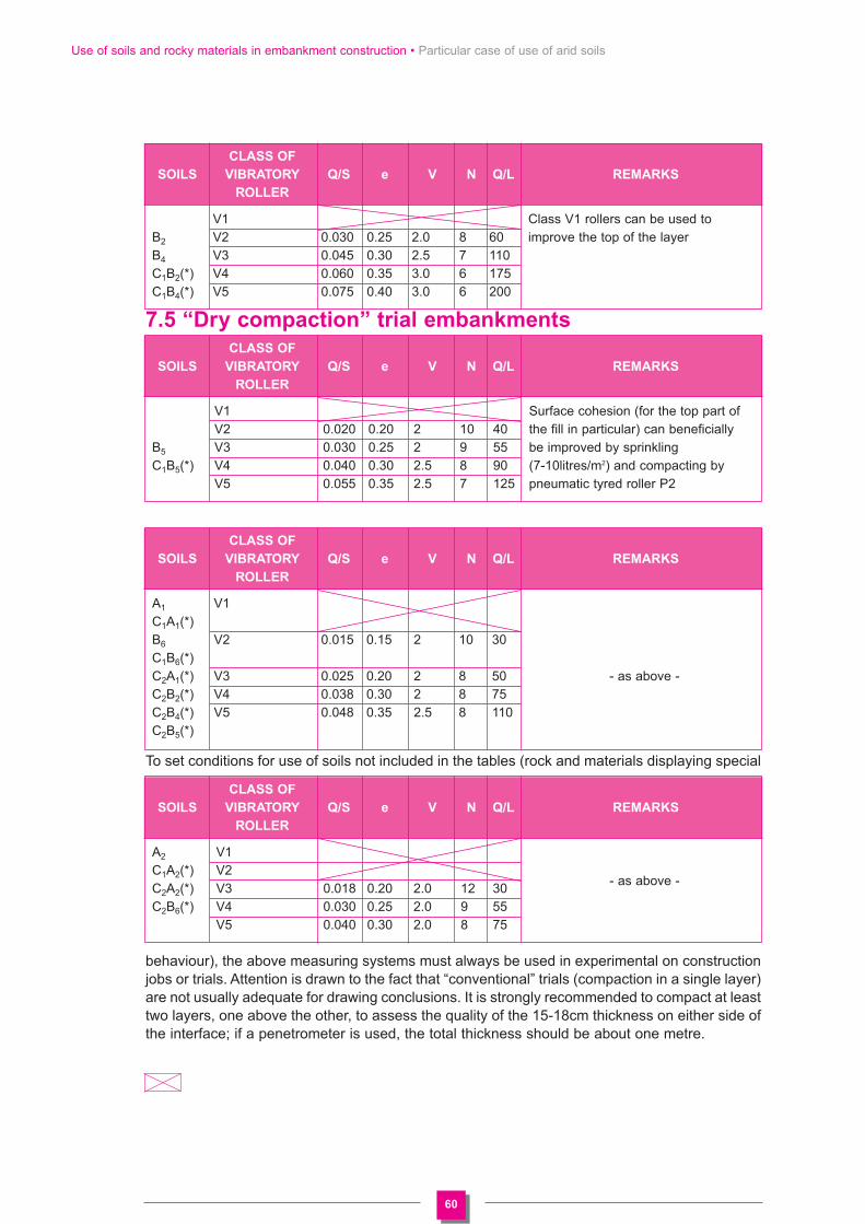
60
Use of soils and rocky materials in embankment construction • Particular case of use of arid soils
7.5 “Dry compaction” trial embankments
To set conditions for use of soils not included in the tables (rock and materials displaying special
behaviour), the above measuring systems must always be used in experimental on constructionjobs or trials. Attention is drawn to the fact that “conventional” trials (compaction in a single layer)are not usually adequate for drawing conclusions. It is strongly recommended to compact at leasttwo layers, one above the other, to assess the quality of the 15-18cm thickness on either side ofthe interface; if a penetrometer is used, the total thickness should be about one metre.
CLASS OF
SOILS VIBRATORY Q/S e V N Q/L REMARKS
ROLLER
V1 Class V1 rollers can be used to B2 V2 0.030 0.25 2.0 8 60 improve the top of the layerB4 V3 0.045 0.30 2.5 7 110C1B2(*) V4 0.060 0.35 3.0 6 175C1B4(*) V5 0.075 0.40 3.0 6 200
CLASS OF
SOILS VIBRATORY Q/S e V N Q/L REMARKS
ROLLER
V1 Surface cohesion (for the top part of V2 0.020 0.20 2 10 40 the fill in particular) can beneficially
B5 V3 0.030 0.25 2 9 55 be improved by sprinkling C1B5(*) V4 0.040 0.30 2.5 8 90 (7-10litres/m2) and compacting by
V5 0.055 0.35 2.5 7 125 pneumatic tyred roller P2
CLASS OF
SOILS VIBRATORY Q/S e V N Q/L REMARKS
ROLLER
A1 V1C1A1(*)B6 V2 0.015 0.15 2 10 30C1B6(*)C2A1(*) V3 0.025 0.20 2 8 50 - as above -C2B2(*) V4 0.038 0.30 2 8 75C2B4(*) V5 0.048 0.35 2.5 8 110C2B5(*)
CLASS OF
SOILS VIBRATORY Q/S e V N Q/L REMARKS
ROLLER
A2 V1C1A2(*) V2
- as above -C2A2(*) V3 0.018 0.20 2.0 12 30C2B6(*) V4 0.030 0.25 2.0 9 55
V5 0.040 0.30 2.0 8 75

Document published by the LCPC under the number 51123111Layout and production: Poly Print Agence / Baton Rouge
Printing: BialecCopyright: 3rd quarter 2003 - N° 59148

Réf : GTRAPrix : 23 € HT
This Manual is an excerpt from the Technical Guidelines on Embankment and Capping LayersConstruction (abbreviated to its French acronym GTR) issued September 1992 in France by LCPCand SETRA. However, this excerpt from the Guidelines concerns only the part dealing with theclassification of natural soils (known as "GIR classification" according to the french norma NF 11-300) and their use as fill for embankments (excluding all reference to organic topsoils and industrialby-products and requirements for their use in capping layers construction).