Practical Engineering Engineering Solutions Guidelines for ... Tech/EDG Equipment Systems Gro… ·...
22
KLM Technology Group Practical Engineering Guidelines for Processing Plant Solutions Engineering Solutions www.klmtechgroup.com Page : 1 of 85 Rev: 02 Rev 1 May 2010 Rev 2 May 2012 KLM Technology Group P. O. Box 281 Bandar Johor Bahru, 80000 Johor Bahru, Johor, West Malaysia Kolmetz Handbook Of Process Equipment Design FURNACE SELECTION, SIZING AND TROUBLESHOOTING (ENGINEERING DESIGN GUIDELINES) Co Author Rev 1 Maidafitri Dewi Priati Rev 2 Aprilia Jaya Author Editor Karl Kolmetz TABLE OF CONTENT INTRODUCTION 4 Scope 4 General Design Consideration 8 DEFINITION 17 NOMENCLATURE 20 THEORY OF THE DESIGN 22 A. Burner 22 B. Radiant Section 27 C. Decoking of fire heater tubes 39 D. Convection Section 41
Transcript of Practical Engineering Engineering Solutions Guidelines for ... Tech/EDG Equipment Systems Gro… ·...

KLM Technology
Group
Practical Engineering Guidelines for Processing
Plant Solutions
Engineering Solutions
www.klmtechgroup.com
Page : 1 of 85
Rev: 02
Rev 1 May 2010 Rev 2 May 2012
KLM Technology Group P. O. Box 281 Bandar Johor Bahru, 80000 Johor Bahru, Johor, West Malaysia
Kolmetz Handbook
Of Process Equipment Design
FURNACE SELECTION, SIZING AND TROUBLESHOOTING
(ENGINEERING DESIGN GUIDELINES)
Co Author Rev 1 Maidafitri Dewi Priati Rev 2 Aprilia Jaya
Author Editor Karl Kolmetz
TABLE OF CONTENT INTRODUCTION 4 Scope 4 General Design Consideration 8 DEFINITION 17 NOMENCLATURE 20 THEORY OF THE DESIGN 22
A. Burner 22
B. Radiant Section 27
C. Decoking of fire heater tubes 39
D. Convection Section 41
KLM Technology Group
Practical Engineering
Guidelines for Processing Plant Solutions
www.klmtechgroup.com
Kolmetz Handbook Of Process Equipment Design
FURNACE SELECTION, SIZING AND
TROUBLESHOOTING
(ENGINEERING DESIGN GUIDELINES)
Page 2 of 85
Rev: 02
May 2012
These design guideline are believed to be as accurate as possible, but are very general and not for specific design cases. They were designed for engineers to do preliminary designs and process specification sheets. The final design must always be guaranteed for the service selected by the manufacturing vendor, but these guidelines will greatly reduce the amount of up front engineering hours that are required to develop the final design. The guidelines are a training tool for young engineers or a resource for engineers with experience. This document is entrusted to the recipient personally, but the copyright remains with us. It must not be copied, reproduced or in any way communicated or made accessible to third parties without our written consent.
E. Stack 47
F. Auxiliary Equipment 52
G. Efficiency of Furnace 61 APPLICATION 68 Application 1: Design of furnace with fuel oil 62 Application 2: Design of furnace with fuel gas 69 REFEREENCE 76 LIST OF TABLE Table 1: The use of fuel at the burner 25 Table 2: Burner capacity 25 Table 3: Common Heater Tube Sizes and Properties 29 Table 4: Design Conditions for Process Heaters 34 Table 5: Thick fins and studs are typically used in the convection section 43 Table 6: Minimum pipe spacing for convection section tubes 44 Table 7: Minimum tube spacing for convection section tubes 44 Table 8: Rotary Sootblower: for Max. Element Length of 10 in 56 Table 9: Rotary Sootblower: for Max. Element Length of 20 in 57
LIST OF FIGURE Figure 1: Vertical cylindrical fired heater: (a) all radiant, and (b) helical coil 6
KLM Technology Group
Practical Engineering
Guidelines for Processing Plant Solutions
www.klmtechgroup.com
Kolmetz Handbook Of Process Equipment Design
FURNACE SELECTION, SIZING AND
TROUBLESHOOTING
(ENGINEERING DESIGN GUIDELINES)
Page 3 of 85
Rev: 02
May 2012
These design guideline are believed to be as accurate as possible, but are very general and not for specific design cases. They were designed for engineers to do preliminary designs and process specification sheets. The final design must always be guaranteed for the service selected by the manufacturing vendor, but these guidelines will greatly reduce the amount of up front engineering hours that are required to develop the final design. The guidelines are a training tool for young engineers or a resource for engineers with experience. This document is entrusted to the recipient personally, but the copyright remains with us. It must not be copied, reproduced or in any way communicated or made accessible to third parties without our written consent.
Figure 2: Horizontal tube cabin fired heaters: (a) cabin with convection section and (b) cabin with dividing bridge wall 7 Figure 3: Hoop-tube fired heater 8 Figure 4: Vertical tube box fired heaters 10 Figure 5: Horizontal tube box fired heaters 11 Figure 6: Multiple cell heaters 12 Figure 7: Helical coil fired heater 13 Figure 8: Typical natural draft burner (combination gas/liquid burner) 23 Figure 9: Typical Axial-Flow Burner Forced Draft Combination Gas/Oil Burner 24 Figure 10: Decoking on the fired heater tubes 40 Figure 11: Damper 50 Figure 12: Square Pitch Finned Tubes : Longitudinal Arrangement 54 Figure 13:. Triangular Pitch Finned Tubes : Longitudinal Arrangement 54 Figure 14: Square Pitch Finned Tubes : Perpendicular Arrangement 55 Figure 15: Triangular Pitch Finned Tubes : Perpendicular Arrangement 55 Figure 16: Fans and Blower: (a) Natural Draft, (b) Forced Draft, (c) Induced Draft and (d) Balance Draft 59 Figure 17: Air Preheater 60
KLM Technology Group
Practical Engineering
Guidelines for Processing Plant Solutions
www.klmtechgroup.com
Kolmetz Handbook Of Process Equipment Design
FURNACE SELECTION, SIZING AND
TROUBLESHOOTING
(ENGINEERING DESIGN GUIDELINES)
Page 4 of 85
Rev: 02
May 2012
These design guideline are believed to be as accurate as possible, but are very general and not for specific design cases. They were designed for engineers to do preliminary designs and process specification sheets. The final design must always be guaranteed for the service selected by the manufacturing vendor, but these guidelines will greatly reduce the amount of up front engineering hours that are required to develop the final design. The guidelines are a training tool for young engineers or a resource for engineers with experience. This document is entrusted to the recipient personally, but the copyright remains with us. It must not be copied, reproduced or in any way communicated or made accessible to third parties without our written consent.
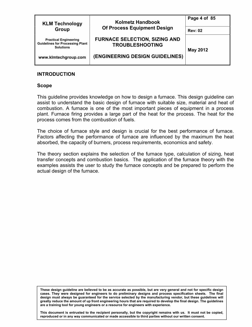
INTRODUCTION Scope This guideline provides knowledge on how to design a furnace. This design guideline can assist to understand the basic design of furnace with suitable size, material and heat of combustion. A furnace is one of the most important pieces of equipment in a process plant. Furnace firing provides a large part of the heat for the process. The heat for the process comes from the combustion of fuels. The choice of furnace style and design is crucial for the best performance of furnace. Factors affecting the performance of furnace are influenced by the maximum the heat absorbed, the capacity of burners, process requirements, economics and safety. The theory section explains the selection of the furnace type, calculation of sizing, heat transfer concepts and combustion basics. The application of the furnace theory with the examples assists the user to study the furnace concepts and be prepared to perform the actual design of the furnace.
KLM Technology Group
Practical Engineering
Guidelines for Processing Plant Solutions
www.klmtechgroup.com
Kolmetz Handbook Of Process Equipment Design
FURNACE SELECTION, SIZING AND
TROUBLESHOOTING
(ENGINEERING DESIGN GUIDELINES)
Page 5 of 85
Rev: 02
May 2012
These design guideline are believed to be as accurate as possible, but are very general and not for specific design cases. They were designed for engineers to do preliminary designs and process specification sheets. The final design must always be guaranteed for the service selected by the manufacturing vendor, but these guidelines will greatly reduce the amount of up front engineering hours that are required to develop the final design. The guidelines are a training tool for young engineers or a resource for engineers with experience. This document is entrusted to the recipient personally, but the copyright remains with us. It must not be copied, reproduced or in any way communicated or made accessible to third parties without our written consent.
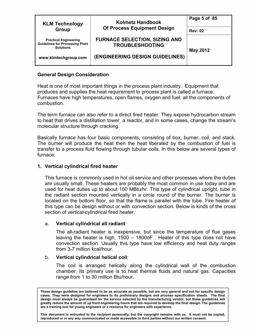
General Design Consideration Heat is one of most important things in the process plant industry. Equipment that produces and supplies the heat requirement to process plant is called a furnace. Furnaces have high temperatures, open flames, oxygen and fuel; all the components of combustion. The term furnace can also refer to a direct fired heater. They expose hydrocarbon stream to heat that drives a distillation tower, a reactor, and in some cases, change the stream's molecular structure through cracking. Basically furnace has four basic components, consisting of box, burner, coil, and stack. The burner will produce the heat then the heat liberated by the combustion of fuel is transfer to a process fluid flowing through tubular coils. In this below are several types of furnace: 1. Vertical cylindrical fired heater
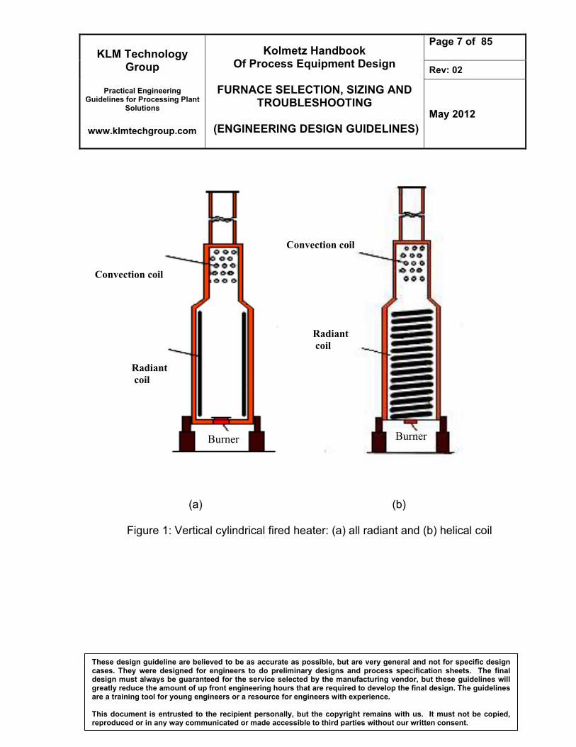
This furnace is commonly used in hot oil service and other processes where the duties are usually small. These heaters are probably the most common in use today and are used for heat duties up to about 150 MBtu/hr. This type of cylindrical upright, tube in the radiant section mounted vertically in a circle round of the burner. The burner is located on the bottom floor, so that the flame is parallel with the tube. Fire heater of this type can be design without or with convection section. Below is kinds of the cross section of vertical-cylindrical fired heater.
a. Vertical cylindrical all radiant:
The all-radiant heater is inexpensive, but since the temperature of flue gases leaving the heater is high, 1500 – 1800oF . Heater of this type does not have convection section. Usually this type have low efficiency and heat duty ranges from 3-7 million kcal/hour.
b. Vertical cylindrical helical coil:
The coil is arranged helically along the cylindrical wall of the combustion chamber. Its primary use is to heat thermal fluids and natural gas. Capacities range from 1 to 30 million Btu/hour.
KLM Technology Group
Practical Engineering
Guidelines for Processing Plant Solutions
www.klmtechgroup.com
Kolmetz Handbook Of Process Equipment Design
FURNACE SELECTION, SIZING AND
TROUBLESHOOTING
(ENGINEERING DESIGN GUIDELINES)
Page 6 of 85
Rev: 02
May 2012
These design guideline are believed to be as accurate as possible, but are very general and not for specific design cases. They were designed for engineers to do preliminary designs and process specification sheets. The final design must always be guaranteed for the service selected by the manufacturing vendor, but these guidelines will greatly reduce the amount of up front engineering hours that are required to develop the final design. The guidelines are a training tool for young engineers or a resource for engineers with experience. This document is entrusted to the recipient personally, but the copyright remains with us. It must not be copied, reproduced or in any way communicated or made accessible to third parties without our written consent.
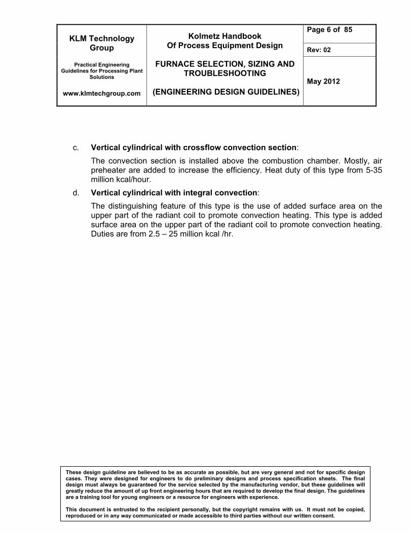
c. Vertical cylindrical with crossflow convection section:
The convection section is installed above the combustion chamber. Mostly, air preheater are added to increase the efficiency. Heat duty of this type from 5-35 million kcal/hour.
d. Vertical cylindrical with integral convection:
The distinguishing feature of this type is the use of added surface area on the upper part of the radiant coil to promote convection heating. This type is added surface area on the upper part of the radiant coil to promote convection heating. Duties are from 2.5 – 25 million kcal /hr.
KLM Technology Group
Practical Engineering
Guidelines for Processing Plant Solutions
www.klmtechgroup.com
Kolmetz Handbook Of Process Equipment Design
FURNACE SELECTION, SIZING AND
TROUBLESHOOTING
(ENGINEERING DESIGN GUIDELINES)
Page 7 of 85
Rev: 02
May 2012
These design guideline are believed to be as accurate as possible, but are very general and not for specific design cases. They were designed for engineers to do preliminary designs and process specification sheets. The final design must always be guaranteed for the service selected by the manufacturing vendor, but these guidelines will greatly reduce the amount of up front engineering hours that are required to develop the final design. The guidelines are a training tool for young engineers or a resource for engineers with experience. This document is entrusted to the recipient personally, but the copyright remains with us. It must not be copied, reproduced or in any way communicated or made accessible to third parties without our written consent.
(a) (b)
Figure 1: Vertical cylindrical fired heater: (a) all radiant and (b) helical coil
Convection coil
Radiant
coil
Burner
Radiant
coil
Burner
Convection coil
KLM Technology Group
Practical Engineering
Guidelines for Processing Plant Solutions
www.klmtechgroup.com
Kolmetz Handbook Of Process Equipment Design
FURNACE SELECTION, SIZING AND
TROUBLESHOOTING
(ENGINEERING DESIGN GUIDELINES)
Page 8 of 85
Rev: 02
May 2012
These design guideline are believed to be as accurate as possible, but are very general and not for specific design cases. They were designed for engineers to do preliminary designs and process specification sheets. The final design must always be guaranteed for the service selected by the manufacturing vendor, but these guidelines will greatly reduce the amount of up front engineering hours that are required to develop the final design. The guidelines are a training tool for young engineers or a resource for engineers with experience. This document is entrusted to the recipient personally, but the copyright remains with us. It must not be copied, reproduced or in any way communicated or made accessible to third parties without our written consent.
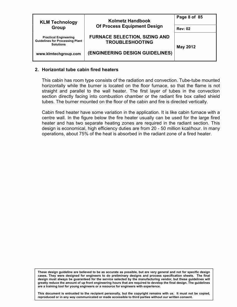
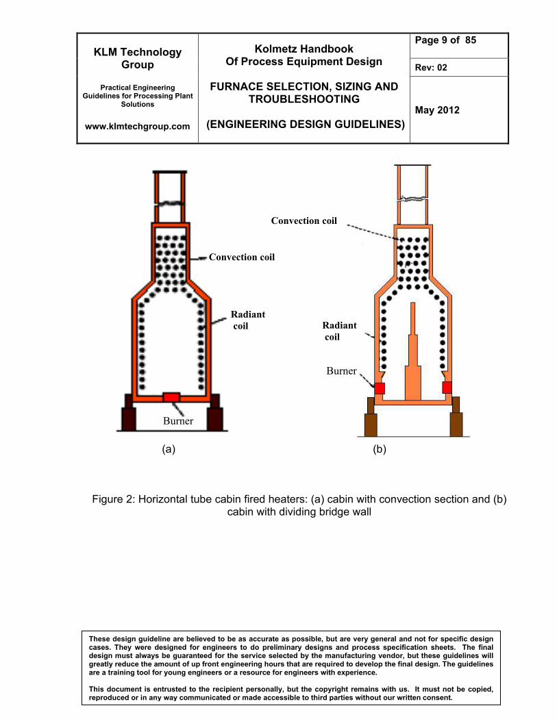
2. Horizontal tube cabin fired heaters This cabin has room type consists of the radiation and convection. Tube-tube mounted horizontally while the burner is located on the floor furnace, so that the flame is not straight and parallel to the wall heater. The first layer of tubes in the convection section directly facing into combustion chamber or the radiant fire box called shield tubes. The burner mounted on the floor of the cabin and fire is directed vertically. Cabin fired heater have some variation in the application. It is like cabin furnace with a centre wall. In the figure below the fire heater usually can be used for the large fired heater and has two separate heating zones are required in the radiant section. This design is economical, high efficiency duties are from 20 - 50 million kcal/hour. In many operations, about 75% of the heat is absorbed in the radiant zone of a fired heater.
KLM Technology Group
Practical Engineering
Guidelines for Processing Plant Solutions
www.klmtechgroup.com
Kolmetz Handbook Of Process Equipment Design
FURNACE SELECTION, SIZING AND
TROUBLESHOOTING
(ENGINEERING DESIGN GUIDELINES)
Page 9 of 85
Rev: 02
May 2012
These design guideline are believed to be as accurate as possible, but are very general and not for specific design cases. They were designed for engineers to do preliminary designs and process specification sheets. The final design must always be guaranteed for the service selected by the manufacturing vendor, but these guidelines will greatly reduce the amount of up front engineering hours that are required to develop the final design. The guidelines are a training tool for young engineers or a resource for engineers with experience. This document is entrusted to the recipient personally, but the copyright remains with us. It must not be copied, reproduced or in any way communicated or made accessible to third parties without our written consent.
(a) (b)
Figure 2: Horizontal tube cabin fired heaters: (a) cabin with convection section and (b) cabin with dividing bridge wall
Convection coil
Radiant
coil
Burner
Convection coil
Radiant
coil
Burner
KLM Technology Group
Practical Engineering
Guidelines for Processing Plant Solutions
www.klmtechgroup.com
Kolmetz Handbook Of Process Equipment Design
FURNACE SELECTION, SIZING AND
TROUBLESHOOTING
(ENGINEERING DESIGN GUIDELINES)
Page 10 of 85
Rev: 02
May 2012
These design guideline are believed to be as accurate as possible, but are very general and not for specific design cases. They were designed for engineers to do preliminary designs and process specification sheets. The final design must always be guaranteed for the service selected by the manufacturing vendor, but these guidelines will greatly reduce the amount of up front engineering hours that are required to develop the final design. The guidelines are a training tool for young engineers or a resource for engineers with experience. This document is entrusted to the recipient personally, but the copyright remains with us. It must not be copied, reproduced or in any way communicated or made accessible to third parties without our written consent.
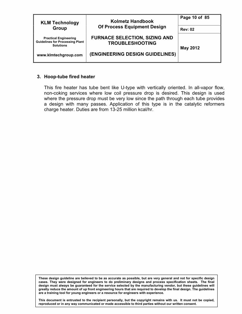
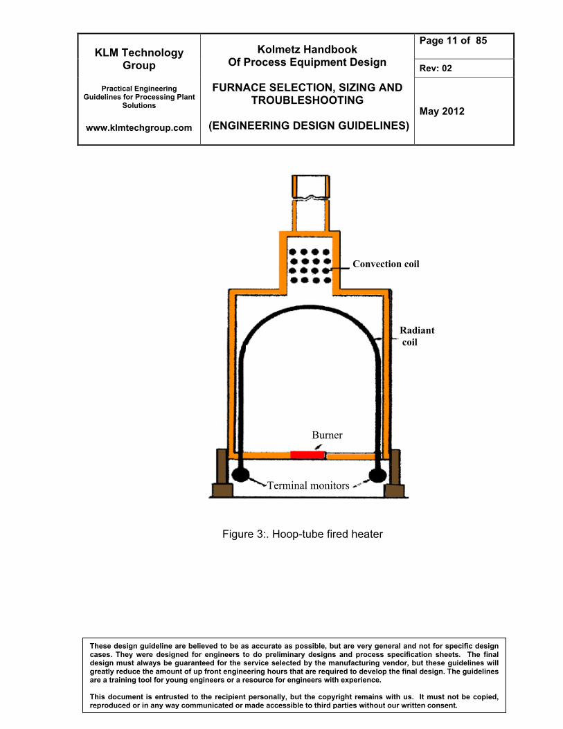
3. Hoop-tube fired heater
This fire heater has tube bent like U-type with vertically oriented. In all-vapor flow, non-coking services where low coil pressure drop is desired. This design is used where the pressure drop must be very low since the path through each tube provides a design with many passes. Application of this type is in the catalytic reformers charge heater. Duties are from 13-25 million kcal/hr.
KLM Technology Group
Practical Engineering
Guidelines for Processing Plant Solutions
www.klmtechgroup.com
Kolmetz Handbook Of Process Equipment Design
FURNACE SELECTION, SIZING AND
TROUBLESHOOTING
(ENGINEERING DESIGN GUIDELINES)
Page 11 of 85
Rev: 02
May 2012
These design guideline are believed to be as accurate as possible, but are very general and not for specific design cases. They were designed for engineers to do preliminary designs and process specification sheets. The final design must always be guaranteed for the service selected by the manufacturing vendor, but these guidelines will greatly reduce the amount of up front engineering hours that are required to develop the final design. The guidelines are a training tool for young engineers or a resource for engineers with experience. This document is entrusted to the recipient personally, but the copyright remains with us. It must not be copied, reproduced or in any way communicated or made accessible to third parties without our written consent.
Figure 3:. Hoop-tube fired heater
Convection coil
Radiant
coil
Burner
Terminal monitors
KLM Technology Group
Practical Engineering
Guidelines for Processing Plant Solutions
www.klmtechgroup.com
Kolmetz Handbook Of Process Equipment Design
FURNACE SELECTION, SIZING AND
TROUBLESHOOTING
(ENGINEERING DESIGN GUIDELINES)
Page 12 of 85
Rev: 02
May 2012
These design guideline are believed to be as accurate as possible, but are very general and not for specific design cases. They were designed for engineers to do preliminary designs and process specification sheets. The final design must always be guaranteed for the service selected by the manufacturing vendor, but these guidelines will greatly reduce the amount of up front engineering hours that are required to develop the final design. The guidelines are a training tool for young engineers or a resource for engineers with experience. This document is entrusted to the recipient personally, but the copyright remains with us. It must not be copied, reproduced or in any way communicated or made accessible to third parties without our written consent.
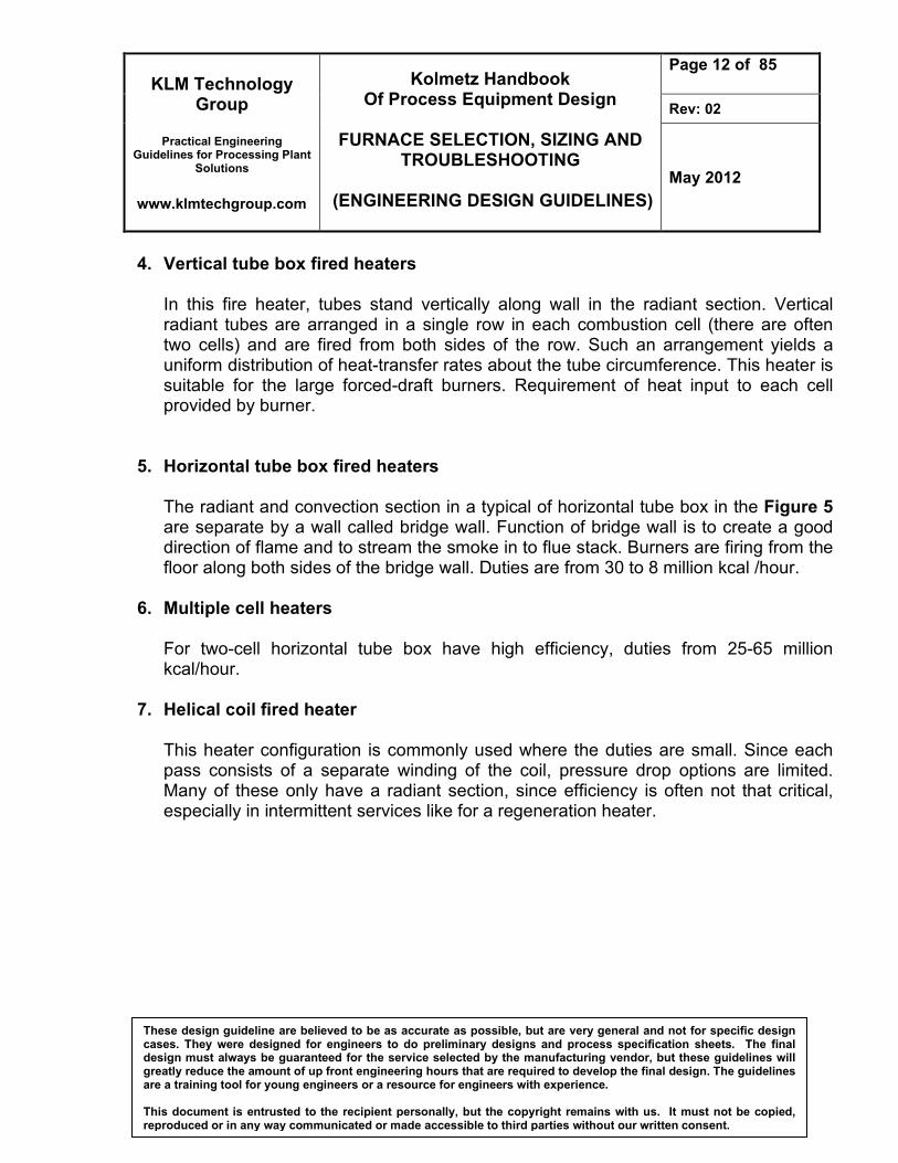
4. Vertical tube box fired heaters In this fire heater, tubes stand vertically along wall in the radiant section. Vertical radiant tubes are arranged in a single row in each combustion cell (there are often two cells) and are fired from both sides of the row. Such an arrangement yields a uniform distribution of heat-transfer rates about the tube circumference. This heater is suitable for the large forced-draft burners. Requirement of heat input to each cell provided by burner.
5. Horizontal tube box fired heaters
The radiant and convection section in a typical of horizontal tube box in the Figure 5 are separate by a wall called bridge wall. Function of bridge wall is to create a good direction of flame and to stream the smoke in to flue stack. Burners are firing from the floor along both sides of the bridge wall. Duties are from 30 to 8 million kcal /hour.
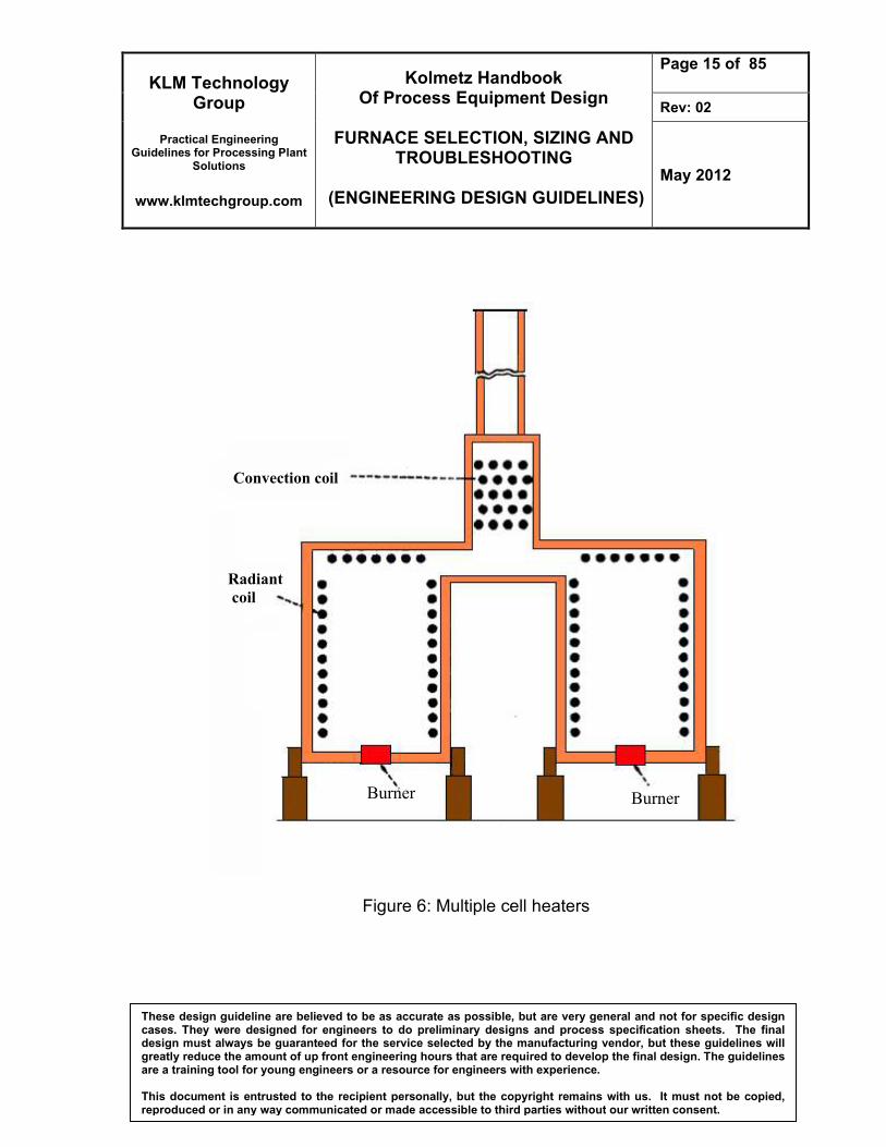
6. Multiple cell heaters For two-cell horizontal tube box have high efficiency, duties from 25-65 million kcal/hour.
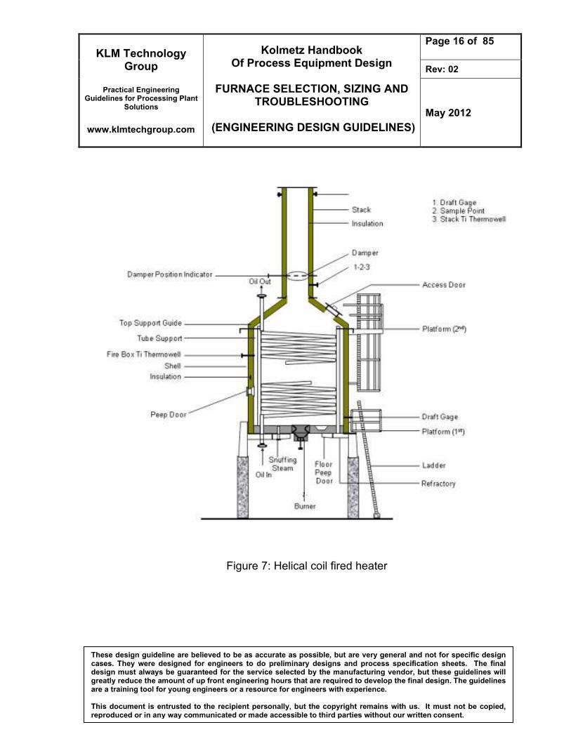
7. Helical coil fired heater This heater configuration is commonly used where the duties are small. Since each pass consists of a separate winding of the coil, pressure drop options are limited. Many of these only have a radiant section, since efficiency is often not that critical, especially in intermittent services like for a regeneration heater.

KLM Technology Group
Practical Engineering
Guidelines for Processing Plant Solutions
www.klmtechgroup.com
Kolmetz Handbook Of Process Equipment Design
FURNACE SELECTION, SIZING AND
TROUBLESHOOTING
(ENGINEERING DESIGN GUIDELINES)
Page 13 of 85
Rev: 02
May 2012
These design guideline are believed to be as accurate as possible, but are very general and not for specific design cases. They were designed for engineers to do preliminary designs and process specification sheets. The final design must always be guaranteed for the service selected by the manufacturing vendor, but these guidelines will greatly reduce the amount of up front engineering hours that are required to develop the final design. The guidelines are a training tool for young engineers or a resource for engineers with experience. This document is entrusted to the recipient personally, but the copyright remains with us. It must not be copied, reproduced or in any way communicated or made accessible to third parties without our written consent.
Figure 4: Vertical tube box fired heaters
To Stack
Burners
2 side fired center
tubes
1 side fired wall
tubes
Forced air
supply direct
KLM Technology Group
Practical Engineering
Guidelines for Processing Plant Solutions
www.klmtechgroup.com
Kolmetz Handbook Of Process Equipment Design
FURNACE SELECTION, SIZING AND
TROUBLESHOOTING
(ENGINEERING DESIGN GUIDELINES)
Page 14 of 85
Rev: 02
May 2012
These design guideline are believed to be as accurate as possible, but are very general and not for specific design cases. They were designed for engineers to do preliminary designs and process specification sheets. The final design must always be guaranteed for the service selected by the manufacturing vendor, but these guidelines will greatly reduce the amount of up front engineering hours that are required to develop the final design. The guidelines are a training tool for young engineers or a resource for engineers with experience. This document is entrusted to the recipient personally, but the copyright remains with us. It must not be copied, reproduced or in any way communicated or made accessible to third parties without our written consent.
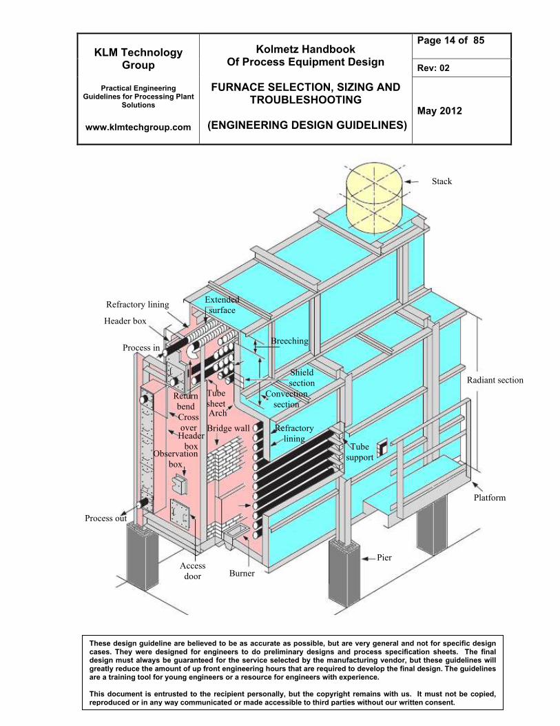
Refractory lining
Platform
Pier
Burner
Process out
Radiant section
Header box
Process in
Access
door
Header
box
Cross
over
Return
bend
Tube
sheet
Observation
box
Arch
Bridge wall
Extended
surface
Breeching
Shield
section
Convection
section
Refractory
lining Tube
support
Stack
KLM Technology Group
Practical Engineering
Guidelines for Processing Plant Solutions
www.klmtechgroup.com
Kolmetz Handbook Of Process Equipment Design
FURNACE SELECTION, SIZING AND
TROUBLESHOOTING
(ENGINEERING DESIGN GUIDELINES)
Page 15 of 85
Rev: 02
May 2012
These design guideline are believed to be as accurate as possible, but are very general and not for specific design cases. They were designed for engineers to do preliminary designs and process specification sheets. The final design must always be guaranteed for the service selected by the manufacturing vendor, but these guidelines will greatly reduce the amount of up front engineering hours that are required to develop the final design. The guidelines are a training tool for young engineers or a resource for engineers with experience. This document is entrusted to the recipient personally, but the copyright remains with us. It must not be copied, reproduced or in any way communicated or made accessible to third parties without our written consent.
Figure 6: Multiple cell heaters
Convection coil
Radiant
coil
Burner Burner
KLM Technology Group
Practical Engineering
Guidelines for Processing Plant Solutions
www.klmtechgroup.com
Kolmetz Handbook Of Process Equipment Design
FURNACE SELECTION, SIZING AND
TROUBLESHOOTING
(ENGINEERING DESIGN GUIDELINES)
Page 16 of 85
Rev: 02
May 2012
These design guideline are believed to be as accurate as possible, but are very general and not for specific design cases. They were designed for engineers to do preliminary designs and process specification sheets. The final design must always be guaranteed for the service selected by the manufacturing vendor, but these guidelines will greatly reduce the amount of up front engineering hours that are required to develop the final design. The guidelines are a training tool for young engineers or a resource for engineers with experience. This document is entrusted to the recipient personally, but the copyright remains with us. It must not be copied, reproduced or in any way communicated or made accessible to third parties without our written consent.
Figure 7: Helical coil fired heater
KLM Technology Group
Practical Engineering
Guidelines for Processing Plant Solutions
www.klmtechgroup.com
Kolmetz Handbook Of Process Equipment Design
FURNACE SELECTION, SIZING AND
TROUBLESHOOTING
(ENGINEERING DESIGN GUIDELINES)
Page 17 of 85
Rev: 02
May 2012
These design guideline are believed to be as accurate as possible, but are very general and not for specific design cases. They were designed for engineers to do preliminary designs and process specification sheets. The final design must always be guaranteed for the service selected by the manufacturing vendor, but these guidelines will greatly reduce the amount of up front engineering hours that are required to develop the final design. The guidelines are a training tool for young engineers or a resource for engineers with experience. This document is entrusted to the recipient personally, but the copyright remains with us. It must not be copied, reproduced or in any way communicated or made accessible to third parties without our written consent.
A Fired heater will work well if designed properly. The design requirements must be properly addressed. Fired heater performance can be measured by a combination of operability and maintenance. There are several factors effecting fired heater selection and design: all-liquid vaporizing service and all-vapor service.
1. Fire heaters in all-liquid or vaporizing service
Inside the tube wall coke may be formed that can interfere with heat transfer process. Fired heaters should be design to minimize coke. Incipient coke begins to form at a film temperature above about 660oF, usually equivalent to a bulk fluid temperature of about 600oF. In other services such as visbreaking and thermal cracking, where fluid cracking is an inherent characteristic of the process, acceptable coke formation and run length can usually be attained if film temperatures do not exceed 910oF equivalent to a bulk fluid temperature of about 880oF.
For reduce the formation of coke, a high inside film coefficient is necessary to minimize the difference between bulk fluid and film temperature. The higher the speed of the mass of the heat transfer coefficient will be better. Therefore, the mass of turbulent flow must be maintaining in the tube.
2. Fire heater in all-vapor service
For this fired heater service is generally not as susceptible to the severe coking problems as those in vaporizing services because of the lighter nature of the process fluid.
KLM Technology Group
Practical Engineering
Guidelines for Processing Plant Solutions
www.klmtechgroup.com
Kolmetz Handbook Of Process Equipment Design
FURNACE SELECTION, SIZING AND
TROUBLESHOOTING
(ENGINEERING DESIGN GUIDELINES)
Page 18 of 85
Rev: 02
May 2012
These design guideline are believed to be as accurate as possible, but are very general and not for specific design cases. They were designed for engineers to do preliminary designs and process specification sheets. The final design must always be guaranteed for the service selected by the manufacturing vendor, but these guidelines will greatly reduce the amount of up front engineering hours that are required to develop the final design. The guidelines are a training tool for young engineers or a resource for engineers with experience. This document is entrusted to the recipient personally, but the copyright remains with us. It must not be copied, reproduced or in any way communicated or made accessible to third parties without our written consent.
To achieve the lowest possible utility cost, a furnace must operate at maximum efficiency. When a furnace is operated properly, the furnace and its parts have a longer working life with minimum repairs. A properly run furnace is a safe furnace. Skillful handing of a furnace means safety for worker. Heat is produce by the ignition of fuel at the burner in the firebox. The tubes along the wall of the firebox are the radiant and the shock bank tubes. These tubes receive radiant heat from the burners. The firebox wall and roof is lined with a material then reduce heat losses and radiates heat back to the tubes. The entire furnace structure must be air tight for efficient furnace operation. Air should only enter at designed entries. An air leak reduces the efficiency of the furnace. Below are design considerations for furnace.
1. Heaters shall be designed for uniform heat distribution
2. Multi-pass heaters shall be designed for hydraulic and thermal symmetry of all passes. The number of passes shall be minimized. Each pass shall be a single circuit
3. Average heat flux density in the radiant section is normally based on single row of tubes with two nominal tube diameter spacing.
4. The maximum allowable inside film temperature for any process service shall not be exceeded in the radiant, shield, or convection sections.
5. minimum radiation loss 2.5 % the total heat input
6. Natural draft needs 25% excess air when oil is the primary fuel and 20 % excess air when fuel gas is the primary fuel. In case of forced draft operation, 20% Excess air for fuel oil and 15% Excess air for fuel gas
7. Heaters shall be designed such that a negative pressure of at least 0.10 inches of water (0.025 kilopascals) is maintained in the radiant and convection sections at maximum heat release with design excess air.
8. The flue gas dew point can be predicted, and the minimum tube-metal temperature can be kept high enough to prevent condensation, if the fuel's sulfur content has been correctly stated. (For estimated flue gas dew points with respect to sulfur content in fuel oil and gas
9. In a well-design heater, the radiant-section heat duty should represent more than 60% to 70% of the total heat duty
KLM Technology Group
Practical Engineering
Guidelines for Processing Plant Solutions
www.klmtechgroup.com
Kolmetz Handbook Of Process Equipment Design
FURNACE SELECTION, SIZING AND
TROUBLESHOOTING
(ENGINEERING DESIGN GUIDELINES)
Page 19 of 85
Rev: 02
May 2012
These design guideline are believed to be as accurate as possible, but are very general and not for specific design cases. They were designed for engineers to do preliminary designs and process specification sheets. The final design must always be guaranteed for the service selected by the manufacturing vendor, but these guidelines will greatly reduce the amount of up front engineering hours that are required to develop the final design. The guidelines are a training tool for young engineers or a resource for engineers with experience. This document is entrusted to the recipient personally, but the copyright remains with us. It must not be copied, reproduced or in any way communicated or made accessible to third parties without our written consent.
10. The bridge wall temperature should range between 800°C to 1,000°C.
11. Higher radiant flux means less heat transfer surface area for a given heat duty; hence, a smaller furnace.
12. The higher the film temperature, the greater is the tendency of the fluid (particularly a hydrocarbon) to crack and deposit a layer of coke.
13. Heat-transfer fluids tend to degrade quickly at high film temperatures.
14. The coke layer acts as an insulator, retarding heat transfer, which could cause tube overheating and lead to tube failure.
15. Also, a heavy coke deposit can restrict the flow through the coil, lowering the inside heat transfer coefficient and further increasing the tube wall temperature.
16. The smallest firebox for a certain duty will obviously produce the cheapest design.
17. The flame impingement and consequent tube failure that could result can be avoided by specifying a minimum safe distance between burners and tubes, based on experience
Followings are the mechanical design for furnace and these will be discussed a much deeper in theory section. 1. Provision for thermal expansion shall take into consideration all specified operating
conditions, including short term conditions such as steam-air decoking.
2. The convection section tube layout shall include space for future installation of soot-blowers or steam lancing doors.
3. The convection section shall incorporate space for future addition of two rows of tubes.
4. When the heater is designed for fuel oil firing, soot-blowers shall be provided for convection section cleaning.
5. Vertical cylindrical heaters shall be designed with maximum height to diameter ratio of 2.75, where the height is the radiant section height and the tube circle diameter.
6. Shield sections shall have at least three rows of bare tubes.
7. Convection sections shall be designed to minimize flue gas bypass. Baffles may be employed.
KLM Technology Group
Practical Engineering
Guidelines for Processing Plant Solutions
www.klmtechgroup.com
Kolmetz Handbook Of Process Equipment Design
FURNACE SELECTION, SIZING AND
TROUBLESHOOTING
(ENGINEERING DESIGN GUIDELINES)
Page 20 of 85
Rev: 02
May 2012
These design guideline are believed to be as accurate as possible, but are very general and not for specific design cases. They were designed for engineers to do preliminary designs and process specification sheets. The final design must always be guaranteed for the service selected by the manufacturing vendor, but these guidelines will greatly reduce the amount of up front engineering hours that are required to develop the final design. The guidelines are a training tool for young engineers or a resource for engineers with experience. This document is entrusted to the recipient personally, but the copyright remains with us. It must not be copied, reproduced or in any way communicated or made accessible to third parties without our written consent.
8. The minimum clearance from grade to burner plenum or register shall be 6 feet 6 inches (2.0 meters) for floor fired heaters.
9. For vertical cylindrical heaters, the maximum radiant straight tube length shall be 60 feet (18.3 meters).
10. For horizontal heaters fired from both ends, the maximum radiation straight tube length shall be 40 feet (12.2 meters).
11. Radiant tubes shall be installed with minimum spacing from refractory or insulation to tube centerline of one and one half nominal tube diameters, with a clearance of not less than 4 inches (10 centimeters) from the refractory or insulation.
12. For horizontal radiant tubes, the minimum clearance from floor refractory to tube outside diameter shall be not less than 12 inches (30 centimeters).
13. The heater arrangement shall allow for replacement of individual tubes without disturbing adjacent tubes.
KLM Technology Group
Practical Engineering
Guidelines for Processing Plant Solutions
www.klmtechgroup.com
Kolmetz Handbook Of Process Equipment Design
FURNACE SELECTION, SIZING AND
TROUBLESHOOTING
(ENGINEERING DESIGN GUIDELINES)
Page 21 of 85
Rev: 02
May 2012
These design guideline are believed to be as accurate as possible, but are very general and not for specific design cases. They were designed for engineers to do preliminary designs and process specification sheets. The final design must always be guaranteed for the service selected by the manufacturing vendor, but these guidelines will greatly reduce the amount of up front engineering hours that are required to develop the final design. The guidelines are a training tool for young engineers or a resource for engineers with experience. This document is entrusted to the recipient personally, but the copyright remains with us. It must not be copied, reproduced or in any way communicated or made accessible to third parties without our written consent.
DEFINITIONS Air Preheater - Heat exchanger device that uses some of the heat in the flue gases to raise the temperature of the air supply to the burners. Breeching - The hood that collects the flue gas at the convection section exit. Bridgewall Temperature - The temperature of the flue gas leaving the radiant section Bulk Temperature - The average temperature of the process fluid at any tube cross section. Center Wall - A refractory wall in the radiant section, which divides it into two separate cells. Coil - A series of straight tube lengths connected by 180o return bends, forming a continuous path through which the process fluid passes and is heated. Convection Section - The portion of a heater, consisting of a bank of tubes, which receives heat from the hot flue gases, mainly by convection. Corbelling - Narrow ledges extending from the convection section side walls to prevent flue gas from flowing preferentially up the side of the convection section, between the wall and the nearest tubes. Crossover - Piping which transfers the process fluid either externally or internally from one section of the heater to another. Damper - A device to regulate flow of gas through a stack or duct and to control draft in a heater. Draft - The negative pressure (vacuum) at a given point inside the heater, usually expressed in inches of water. Excess Air - The percentage of air in the heater in excess of the stoichiometric amount required for combustion.
KLM Technology Group
Practical Engineering
Guidelines for Processing Plant Solutions
www.klmtechgroup.com
Kolmetz Handbook Of Process Equipment Design
FURNACE SELECTION, SIZING AND
TROUBLESHOOTING
(ENGINEERING DESIGN GUIDELINES)
Page 22 of 85
Rev: 02
May 2012
These design guideline are believed to be as accurate as possible, but are very general and not for specific design cases. They were designed for engineers to do preliminary designs and process specification sheets. The final design must always be guaranteed for the service selected by the manufacturing vendor, but these guidelines will greatly reduce the amount of up front engineering hours that are required to develop the final design. The guidelines are a training tool for young engineers or a resource for engineers with experience. This document is entrusted to the recipient personally, but the copyright remains with us. It must not be copied, reproduced or in any way communicated or made accessible to third parties without our written consent.
Extended Surface - Surface added to the outside of bare tubes in the convection section to provide more heat transfer area. Film - A thin fluid layer adjacent to a pipe wall that remains in laminar flow, even when the bulk flow is turbulent. Film Temperature - The maximum temperature in the film, at the tube wall. Fire Box - A term used to describe the structure which surrounds the radiant coils and into which the burners protrude. Flue Gas - A mixture of gaseous products resulting from combustion of the fuel. Fouling - The building up of a film of dirt, ash, soot or coke on heat transfer surfaces, resulting in increased resistance to heat flow. Forced Draft - Use of a fan to supply combustion air to the burners and to overcome the pressure drop through the burners. Fired Heater Efficiency - The ratio of heat absorbed to heat fired, on a lower heating value basis. Header Box - The compartment at the end of the convection section where the headers are located. Heat Available - The heat absorbed from the products of combustion (flue gas) as they are cooled from the flame temperature to a given flue gas temperature. Heat Density - The rate of heat transfer per unit area to a tube, usually based on total outside surface area. Heat Duty - The total heat absorbed by the process fluid, usually expressed in MBtu/hr