PQM II Retrofits - GE Grid Solutions · FEATURE MTM PLUS MPM PQM PQM II ... Time Stamp Resolution...
4
Grid Solutions Monitoring & Metering • Current and Voltage measurements (Ia Ib Ic In, Va Vb Vc Vab Vbc Vca) • V I unbalance • True PF Crest and K factor • Hz, W, VAR, VA • Wh, VARh, Vah, W cost • Demand: W VAR VA • Power Factor- Disturbance recording and waveform capture • Harmonic analysis through 63rd with THD and TIF • Event Recorder – up to 150 events • Data Logger – up to 98,000 events • Voltage Disturbance Recorder (VDR) – up to 500 events Communications • Front RS232 serial port • Two rear RS485 serial ports with Modbus and DNP 3.0 protocol • Ethernet connectivity via MultiNet • Software based setup and monitoring with EnerVista TM Protection & Control • Unbalance: A, V, W, Var, VA, Varh, Wh, PF, Hz • Demand: A, W, Var, VA • Load shedding • Power factor control • Pulse input totalizing • Capacitor Bank Switching Replace PQM, MPM, and MTM Plus meters with the PQM II Power Quality Meter The PQM II Power Quality Meter further improves upon the metering, recording and communications functionality of the earlier generation devices including the PQM Power Quality Meter (discontinued 2013), MPM Motor Protection Meters (discontinued 2013) and MTM Plus Meter Transducer Module (discontinued 1998). The PQM II is an ideal choice when continuous monitoring of a three-phase system is required. It provides metering for critical asset and system parameters such as current, voltage, real and reactive power, energy use, cost of power, power factor and frequency. Furthermore, programmable set points and 4 assignable output relays provide control functionality for specific applications. This includes alarms for over/under current or voltage, unbalance, demand based load shedding, and capacitor power factor correction control. More complex control is available using the 4 switch inputs that can be used for status indications such as breaker open/closed, flow information etc. Key Benefits • Increased metering recording functionality including Voltage Disturbance Recorder (VDR) to monitor voltage dips (voltage sags) and voltage spikes (voltage swells) with capacity for 500 sag/swell events. • Alarm trigger from any assignable output • Easy integration to DCS or SCADA systems with standard Modbus and DNP 3.0 Communications Protocol • Compatible with GE MultiNet Serial to Ethernet Converter • Versatile mounting options for easy installation • Easy to use keypad and large illuminated display • Flash upgradable for future requirements Applications • Commercial, Industrial and Utility Power Quality Applications for medium and low voltage systems • Metering and asset monitoring of distribution feeders, transformers, generators, capacitor banks and motors • Specialized control applications for demand load shedding, power factor, etc. • Monitoring of assets in challenging Industrial environments PQM II Retrofits
-
Upload
hoangnguyet -
Category
Documents
-
view
228 -
download
0
Transcript of PQM II Retrofits - GE Grid Solutions · FEATURE MTM PLUS MPM PQM PQM II ... Time Stamp Resolution...

Grid Solutions
Monitoring & Metering• Current and Voltage measurements (Ia Ib Ic In,
Va Vb Vc Vab Vbc Vca)
• V I unbalance
• True PF Crest and K factor
• Hz, W, VAR, VA
• Wh, VARh, Vah, W cost
• Demand: W VAR VA
• Power Factor- Disturbance recording and waveform capture
• Harmonic analysis through 63rd with THD and TIF
• Event Recorder – up to 150 events
• Data Logger – up to 98,000 events
• Voltage Disturbance Recorder (VDR) – up to 500 events
Communications• Front RS232 serial port
• Two rear RS485 serial ports with Modbus and DNP 3.0 protocol
• Ethernet connectivity via MultiNet
• Software based setup and monitoring with EnerVistaTM
Protection & Control• Unbalance: A, V, W, Var, VA, Varh, Wh, PF, Hz
• Demand: A, W, Var, VA
• Load shedding
• Power factor control
• Pulse input totalizing
• Capacitor Bank Switching
Replace PQM, MPM, and MTM Plus meters with the PQM II Power Quality Meter The PQM II Power Quality Meter further improves upon the metering, recording and communications functionality of the earlier generation devices including the PQM Power Quality Meter (discontinued 2013), MPM Motor Protection Meters (discontinued 2013) and MTM Plus Meter Transducer Module (discontinued 1998).
The PQM II is an ideal choice when continuous monitoring of a three-phase system is required. It provides metering for critical asset and system parameters such as current, voltage, real and reactive power, energy use, cost of power, power factor and frequency. Furthermore, programmable set points and 4 assignable output relays provide control functionality for specific applications. This includes alarms for over/under current or voltage, unbalance, demand based load shedding, and capacitor power factor correction control. More complex control is available using the 4 switch inputs that can be used for status indications such as breaker open/closed, flow information etc.
Key Benefits• Increased metering recording functionality including Voltage Disturbance Recorder (VDR) to monitor
voltage dips (voltage sags) and voltage spikes (voltage swells) with capacity for 500 sag/swell events.
• Alarm trigger from any assignable output
• Easy integration to DCS or SCADA systems with standard Modbus and DNP 3.0 Communications Protocol
• Compatible with GE MultiNet Serial to Ethernet Converter
• Versatile mounting options for easy installation
• Easy to use keypad and large illuminated display
• Flash upgradable for future requirements
Applications• Commercial, Industrial and Utility Power Quality Applications for medium and low voltage systems
• Metering and asset monitoring of distribution feeders, transformers, generators, capacitor banks and motors
• Specialized control applications for demand load shedding, power factor, etc.
• Monitoring of assets in challenging Industrial environments
PQM II Retrofits
GEGridSolutions.com2
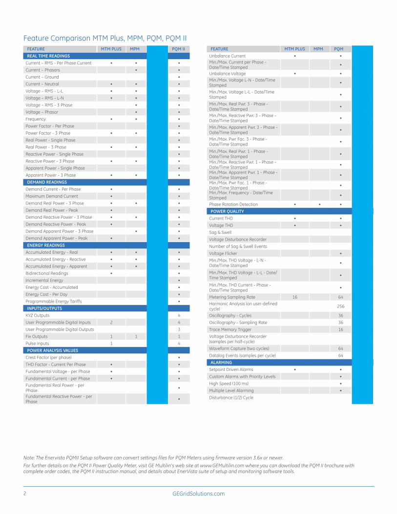
FEATURE MTM PLUS MPM PQM PQM IIREAL TIME READINGS
Current – RMS - Per Phase Current • • • •Current – Phasors • • •Current – Ground • •Current – Neutral • • • •Voltage – RMS - L-L • • • •Voltage – RMS - L-N • • • •Voltage – RMS - 3 Phase • • •Voltage – Phasor • • •Frequency • • • •Power Factor - Per Phase • •Power Factor - 3 Phase • • • •Real Power - Single Phase • •Real Power - 3 Phase • • • •Reactive Power - Single Phase • •Reactive Power - 3 Phase • • • •Apparent Power - Single Phase • •Apparent Power - 3 Phase • • • •DEMAND READINGS
Demand Current - Per Phase • • •Maximum Demand Current • •Demand Real Power - 3 Phase • • • •Demand Real Power - Peak • • •Demand Reactive Power - 3 Phase • • • •Demand Reactive Power - Peak • • •Demand Apparent Power - 3 Phase • • •Demand Apparent Power - Peak • • •ENERGY READINGS
Accumulated Energy - Real • • • •Accumulated Energy - Reactive • • • •Accumulated Energy - Apparent • • • •Bidirectional Readings • • •Incremental Energy • •Energy Cost - Accumulated • •Energy Cost - Per Day • •Programmable Energy Tariffs • •INPUTS/OUTPUTS
KYZ Outputs 4 4User Programmable Digital Inputs 2 4 4User Programmable Digital Outputs 3 3Fix Outputs 1 1 1 1Pulse Inputs 1 4 4POWER ANALYSIS VALUES
Crest Factor (per phase) • •THD Factor - Current Per Phase • • •Fundamental Voltage - per Phase • • •Fundamental Current - per Phase • • •Fundamental Real Power - per Phase • •
Fundamental Reactive Power - per Phase • •
Feature Comparison MTM Plus, MPM, PQM, PQM IIFEATURE MTM PLUS MPM PQM PQM II
Unbalance Current • • •Min./Max. Current per Phase - Date/Time Stamped • •
Unbalance Voltage • • •Min./Max. Voltage L-N - Date/Time Stamped • •
Min./Max. Voltage L-L - Date/Time Stamped • •
Min./Max. Real Pwr. 3 - Phase - Date/Time Stamped • •
Min./Max. Reactive Pwr. 3 - Phase - Date/Time Stamped • •
Min./Max. Apparent Pwr. 3 - Phase - Date/Time Stamped • •
Min./Max. Pwr Fac. 3 - Phase - Date/Time Stamped • •
Min./Max. Real Pwr. 1 - Phase - Date/Time Stamped • •
Min./Max. Reactive Pwr. 1 - Phase - Date/Time Stamped • •
Min./Max. Apparent Pwr. 1 - Phase - Date/Time Stamped • •
Min./Max. Pwr Fac. 1 - Phase - Date/Time Stamped • •
Min./Max. Frequency - Date/Time Stamped • •
Phase Rotation Detection • • • •POWER QUALITY
Current THD • • •Voltage THD • • •Sag & Swell •Voltage Disturbance Recorder •Number of Sag & Swell Events 500Voltage Flicker • •Min./Max. THD Voltage - L-N - Date/Time Stamped • •
Min./Max. THD Voltage - L-L - Date/Time Stamped • •
Min./Max. THD Current - Phase - Date/Time Stamped • •
Metering Sampling Rate 16 64 64Harmonic Analysis (on user-defined cycle) 256 256
Oscillography - Cycles 36 36Oscillography - Sampling Rate 36 36Trace Memory Trigger 16 16Voltage Disturbance Recorder (samples per half-cycle) 8
Waveform Capture (two cycles) 64 64Datalog Events (samples per cycle) 64 64ALARMING
Setpoint Driven Alarms • • •Custom Alarms with Priority Levels • •High Speed (100 ms) • •Multiple Level Alarming • •Disturbance (1/2) Cycle •
Note: The Enervista PQMII Setup software can convert settings files for PQM Meters using firmware version 3.6x or newer.
For further details on the PQM II Power Quality Meter, visit GE Multilin’s web site at www.GEMultilin.com where you can download the PQM II brochure with complete order codes, the PQM II instruction manual, and details about EnerVista suite of setup and monitoring software tools.
GEGridSolutions.com 3
Ordering the PQM II Power Quality MeterFor the full benefits of upgrading to the PQM II, the order code PQMII-T20-C-A is recommended.
PQM II Options
Note: PQM order code options are the same as for PQM II, with additional features included in the PQM II meter.
T20: Transducer option; 4 isolated analog outputs 0 – 20 mA and 4 – 20 mA, 4 – 20 mA analog input, 2nd RS485 port
T1: Transducer option; 4 isolated analog outputs 0 – 1 mA, 4 – 20 mA analog input, 2nd RS485 port
C: Control option; 3 additional programmable output relays (total of 4), 4-programmable switch inputs
A: Power analysis option; harmonic analysis, triggered trace memory waveform capture, event record, data logger, voltage disturbance recorder (VDR)
Control Power: Standard: 90 – 300 VDC/70 – 265 VAC
Modifications:
• MOD 501: 20 – 60 VDC/20 – 48 VAC
• MOD 504: Removable terminal blocks
• MOD 525: Harsh Environments Conformal Coating
MPM Options
The MPM can be replaced by PQMII-T1 or PQMII-T20, however, we recommend PQMII-T20-C-A. For low control power, MOD 501 is available.
MPM: Basic unit , all current/voltage/power measurements, 1 x 269/269 Plus Comm port, Fail-safe Form C Output Relay
LO: 20 – 60 VDC, 20 – 48 VAC 50/60 Hz
HI: 90 – 300 VDC, 70 – 265 VAC 50/60 Hz
A1: Four 0 – 1 mA analog outputs
A20: Four 4 – 20 mA analog outputs
MTM Plus Options
If required, a PQM II mounting plate is available in order to replace an MTM Plus meter.
120: 90 – 140 VAC
240: 200 – 260 VAC
S: Separate Power
P: PT Power
A01: 0 – 1 mA
A20: 4 – 20 mA
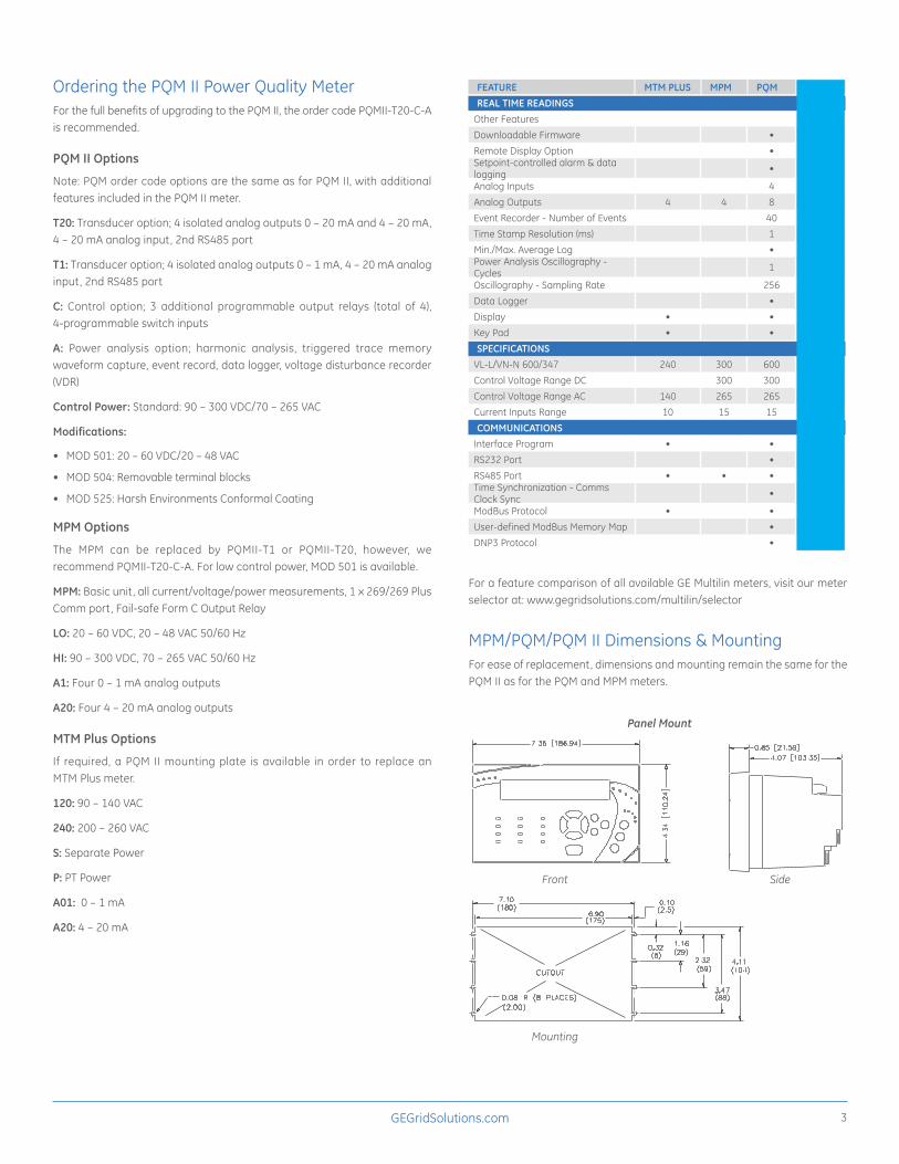
FEATURE MTM PLUS MPM PQM PQM IIREAL TIME READINGS
Other FeaturesDownloadable Firmware • •Remote Display Option •Setpoint-controlled alarm & data logging • •
Analog Inputs 4 4Analog Outputs 4 4 8 8Event Recorder - Number of Events 40 150Time Stamp Resolution (ms) 1 1Min./Max. Average Log • •Power Analysis Oscillography - Cycles 1 1
Oscillography - Sampling Rate 256 256Data Logger • •Display • • •Key Pad • • •SPECIFICATIONS
VL-L/VN-N 600/347 240 300 600 600Control Voltage Range DC 300 300 300Control Voltage Range AC 140 265 265 265Current Inputs Range 10 15 15 15COMMUNICATIONS
Interface Program • • •RS232 Port • •RS485 Port • • • •Time Synchronization - Comms Clock Sync • •
ModBus Protocol • • •User-defined ModBus Memory Map • •DNP3 Protocol • •
For a feature comparison of all available GE Multilin meters, visit our meter selector at: www.gegridsolutions.com/multilin/selector
MPM/PQM/PQM II Dimensions & MountingFor ease of replacement, dimensions and mounting remain the same for the PQM II as for the PQM and MPM meters.
Panel Mount
Front
Mounting
Side
GEA-32002-(E)English171120
GEGridSolutions.comIEC is a registered trademark of Commission Electrotechnique Internationale. IEEE is a registered trademark of the Institute of Electrical Electronics Engineers, Inc. Modbus is a registered trademark of Schneider Automation. NERC is a registered trademark of North American Electric Reliability Council. ANSI is a registered trademark of American National Standards.
GE, the GE monogram, Multilin, FlexCurves and EnerVista are trademarks of General Electric Company. GE reserves the right to make changes to specifications of products described at any time without notice and without obligation to notify any person of such changes.
Copyright 2017, General Electric Company. All Rights Reserved.
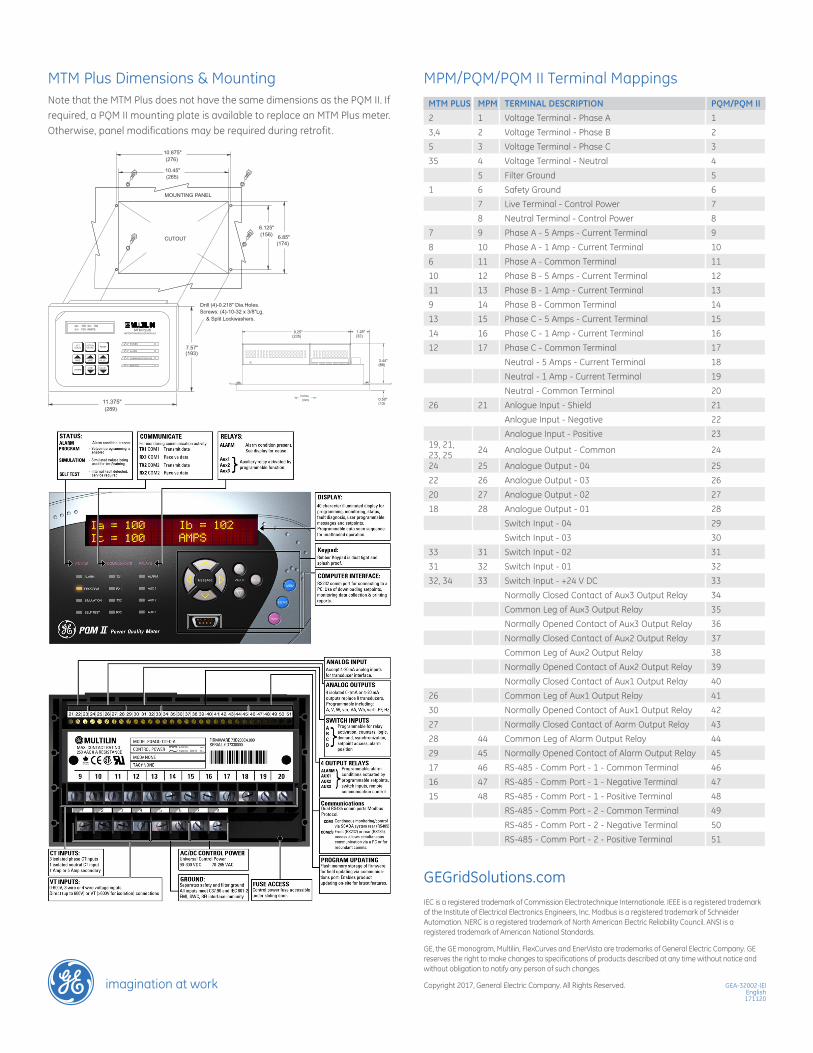
MTM Plus Dimensions & MountingNote that the MTM Plus does not have the same dimensions as the PQM II. If required, a PQM II mounting plate is available to replace an MTM Plus meter. Otherwise, panel modifications may be required during retrofit .
MPM/PQM/PQM II Terminal MappingsMTM PLUS MPM TERMINAL DESCRIPTION PQM/PQM II2 1 Voltage Terminal - Phase A 13,4 2 Voltage Terminal - Phase B 25 3 Voltage Terminal - Phase C 335 4 Voltage Terminal - Neutral 4
5 Filter Ground 51 6 Safety Ground 6
7 Live Terminal - Control Power 78 Neutral Terminal - Control Power 8
7 9 Phase A - 5 Amps - Current Terminal 98 10 Phase A - 1 Amp - Current Terminal 106 11 Phase A - Common Terminal 1110 12 Phase B - 5 Amps - Current Terminal 1211 13 Phase B - 1 Amp - Current Terminal 139 14 Phase B - Common Terminal 1413 15 Phase C - 5 Amps - Current Terminal 1514 16 Phase C - 1 Amp - Current Terminal 1612 17 Phase C - Common Terminal 17
Neutral - 5 Amps - Current Terminal 18Neutral - 1 Amp - Current Terminal 19Neutral - Common Terminal 20
26 21 Anlogue Input - Shield 21Anlogue Input - Negative 22Analogue Input - Positive 23
19, 21, 23, 25 24 Analogue Output - Common 24
24 25 Analogue Output - 04 2522 26 Analogue Output - 03 2620 27 Analogue Output - 02 2718 28 Analogue Output - 01 28
Switch Input - 04 29Switch Input - 03 30
33 31 Switch Input - 02 3131 32 Switch Input - 01 3232, 34 33 Switch Input - +24 V DC 33
Normally Closed Contact of Aux3 Output Relay 34Common Leg of Aux3 Output Relay 35Normally Opened Contact of Aux3 Output Relay 36Normally Closed Contact of Aux2 Output Relay 37Common Leg of Aux2 Output Relay 38Normally Opened Contact of Aux2 Output Relay 39Normally Closed Contact of Aux1 Output Relay 40
26 Common Leg of Aux1 Output Relay 4130 Normally Opened Contact of Aux1 Output Relay 4227 Normally Closed Contact of Aarm Output Relay 4328 44 Common Leg of Alarm Output Relay 4429 45 Normally Opened Contact of Alarm Output Relay 4517 46 RS-485 - Comm Port - 1 - Common Terminal 4616 47 RS-485 - Comm Port - 1 - Negative Terminal 4715 48 RS-485 - Comm Port - 1 - Positive Terminal 48
RS-485 - Comm Port - 2 - Common Terminal 49RS-485 - Comm Port - 2 - Negative Terminal 50RS-485 - Comm Port - 2 - Positive Terminal 51
METER/TRANSDUCER MODULEMTM PLUS
SERVICE
COMMUNICATION FAIL
ALARM
POWER
PAGE
STOREVALUELINE
LINE VALUE
RESETACTUALVALUESPOINTS
SET
Ia= 100 Ib= 102Ic= 100 AMPS
(193)
(289)
7.57"
11.375"
Screws: (4)-10-32 x 3/8"Lg.Drill (4)-0.218" Dia.Holes.
(174)6.85"(156)
6.125"
(276)
(265)
10.875"
10.45"
& Split Lockwashers.
(mm)inches
MOUNTING PANEL
CUTOUT
998063A2.DWG(mm)
inches
(192)
(289)
7.57"
11.375"(13)
3.44"
1.25"9.25"(235) (32)
0.50"
(88)
METER/TRANSDUCER MODULE
MTM PLUS
SERVICE
COMMUNICATION FAIL
ALARM
POWER
PAGE
STOREVALUELINE
LINE VALUE
RESETACTUALVALUESPOINTS
SET
Ia= 100 Ib= 102Ic= 100 AMPS
+
998039A3.DWG