PPT and PPTR User’s Manual - Honeywell Aerospace/media/aerospace/files/user... · The Honeywell...
90
Honeywell Precision Pressure Transducers PPT and PPTR User’s Manual
Transcript of PPT and PPTR User’s Manual - Honeywell Aerospace/media/aerospace/files/user... · The Honeywell...

Honeywell Precision Pressure Transducers
PPT and PPTR User’s Manual

ADS-14052, Revision B, 10/16 Email: [email protected] Web: www.pressuresensing.com
No part of this manual may be reproduced or transmitted in any form or by any means, electronic or mechanical, including photocopying and recording, for any purpose, without the express written permission of Honeywell, Inc. Honeywell reserves the right to make changes to any products or technology herein to improve reliability, function or design. Honeywell does not assume any liability arising out of the application or use of any product or circuit described herein; neither does it convey any license under its patent rights nor the rights of others.
PPT User’s Manual Contents
0 USER MANUAL CONTENT ..................................................................................... 1
1 INTRODUCTION ....................................................................................................... 2
1.1 Product Overview ............................................................................................ 2
1.2 Hardware Description .................................................................................... 2
2 GETTING STARTED ................................................................................................. 3
2.1 Overview .......................................................................................................... 3
2.2 Equipment Needed ......................................................................................... 3
2.3 Terminal Program Settings ............................................................................ 3
2.4 Initial Turn-On Response ............................................................................... 4
2.5 Command Format ........................................................................................... 4
2.6 Step-By-Step Examples .................................................................................. 5
2.7 Command Functional Groups ........................................................................ 7
3 COMMANDS - QUICK REFERENCE ...................................................................... 9
4 FUNCTIONAL OPERATION .................................................................................... 13
4.1 Overview .......................................................................................................... 13
4.2 What Is Integration? ....................................................................................... 14
4.3 Pressure Reading Control ............................................................................... 14
4.4 Output Voltage Control ................................................................................... 16
4.5 Pressure Window Control ............................................................................... 16
4.6 Customized Pressure Range ........................................................................... 17
4.7 Setting Pressure Set Points ............................................................................ 18
4.8 PPT Analog Output Configurations ............................................................... 19
4.9 Command Illustrations ................................................................................... 20
4.10 Pressure Reading Decimal Position ............................................................... 24
4.11 PPT Addressing ............................................................................................... 25
i
PPT User’s Manual Contents (cont’d)
5 COMMANDS .............................................................................................................. 28
5.1 Command Format ........................................................................................... 28
5.2 Information Request Commands ................................................................... 29
5.3 Action Directing Commands ........................................................................... 29
5.4 Command Replies—General .......................................................................... 29
5.5 ASCII Format Replies ..................................................................................... 30
5.6 Binary Format Replies ................................................................................... 31
5.7 Command And Reply Sequencing .................................................................. 34
5.8 Command Errors ............................................................................................. 35
5.9 Command Summary Table ............................................................................. 37
5.10 Command Descriptions ................................................................................... 39
6 ELECTRICAL CONNECTIONS ................................................................................ 73
7 TIMING DIAGRAMS ................................................................................................. 75
8 SPECIFICATIONS ..................................................................................................... 78
9 DIMENSIONS ............................................................................................................ 80 ii
Figure 4.1
Figure 4.2
Figure 4.3
Figure 4.4
Figure 4.5
Figure 4.6
Figure 4.7
Figure 4.8
Figure 4.9
Figure 4.10
Figure 4.11
Figure 4.12
Figure 4.13
Figure 4.14
Figure 4.15
Figure 4.16
Figure 4.17
Figure 4.18
Figure 4.19
Figure 4.20
Figure 4.21
Figure 5.1
Figure 5.2
Figure 6.1
Figure 6.2
Figure 6.3
Figure 6.4
Figure 6.5 Figure 7.1
Figure 7.2
Figure 7.3
Figure 7.4
Figure 7.5
Figure 7.6
Figure 9.1
Figure 9.2
Figure 9.3
Figures
PPT Block Diagram .......................................................................................... 13
Pressure Reading Control ................................................................................ 15
Factory Set Output Levels ............................................................................... 16
User Modified Output Levels ........................................................................... 17
User Modified Pressure Span .......................................................................... 17
Custom Slope (X=) Options .............................................................................. 17
Custom Offset (Z=) Options ............................................................................. 17
Pressure Set Point Set ..................................................................................... 18
Deadband on Set Point ..................................................................................... 18
PPT Pressure to Analog Voltage ...................................................................... 19
PPT Pressure Readings and Analog Voltage Control ..................................... 19
Sensing Remote Analog Pressure .................................................................... 19
Integration (I=) Command, Example 1 ........................................................... 20
Integration (I=) Command, Example 2 ........................................................... 21
S2 Speed Shift Command Example ................................................................. 21
S5 Speed Shift Command Example ................................................................. 22
Deadband and Integration (DI) Command Examples ........................... 22 – 23
Idle Count (IC) Command Example ................................................................ 23
Synchronize Integration Cycles (SI) Command Example .............................. 24
RS-232 PPT Ring Network .............................................................................. 25
RS-485 PPT Multidrop Network ..................................................................... 26
Single PPT Command and Reply .................................................................... 34
Multiple PPT Network Command and Replies ............................................... 35
PPT Electrical Connector Pin Assignments .................................................... 73
Connection for RS-232 Operation and Analog Output ................................... 73
Connection for RS-485 Operation and Analog Output ................................... 74
Connection for Analog Output and Battery Operation ................................... 74
Connection for Computer Operation and
User Controlled Analog Voltage Output ...................................................... 74
Default Single Pressure Reading Timing Diagram ........................................ 75
Default Continuous Pressure Reading Timing Diagram ................................ 75
Continuous Pressure (with IC = 1) Timing Diagram ...................................... 75
Timing Diagram for 20 Readings Per Second ................................................. 76
Timing Diagram for 50 Readings Per Second ................................................. 76
Timing Diagram for 120 Readings Per Second ............................................... 76
PPT Case Outline ............................................................................................. 80
Electrical Connector ......................................................................................... 80
PPTR Case Outline .......................................................................................... 81 iii
Table 1.1
Table 4.1
Table 4.2
Table 5.1
Table 5.2
Table 5.3
Table 5.4
Table 5.5
Table 7.1
Table 7.2
Table 9.1
Table 9.2
Table 9.3
Tables
Various Digital and Analog Output Modes ........................................................... 2
PPT to PPT Remote Sensing Setup Commands ................................................. 20
Decimal Place Locations for Pressure Readings ................................................ 24
Header Description for Binary Format Pressure Readings .............................. 31
Binary Format Character Codes ......................................................................... 33
Command List ..................................................................................................... 37
Command Factory Default List .......................................................................... 39
Display Units Options ......................................................................................... 47
Transmission Times at Selected Baud Rate ....................................................... 77
Number of Bytes in Various Replies ................................................................... 77
ASCII Conversion Table ...................................................................................... 81
RS-232 Standard Pin Connections ..................................................................... 81
Electrical Signal Levels ....................................................................................... 81
iv
0 USERS MANUAL CONTENT
This user’s manual is divided into the following sections.
Section 1 Introduction—Product overview and hardware description.
Section 2 Getting Started—Lists equipment and procedures necessary to operate the PPT and provides a few simple command examples, which will get first-time users acquainted with the command structure.
Section 3 Commands: Quick Reference—A brief description of each command with typical PPT input and response examples.
Section 4 Functional Operation
Section 5 Commands—Contains a detailed description of the command structure, func- tional groupings and all user commands.
Section 6 Electrical Connections—Contains wiring diagrams for various PPT electrical connections.
Section 7 Timing Diagrams—Illustrates RS-232 serial port timing for command and reply interaction.
Section 8 Specifications—Contains electrical and environmental specifications.
Section 9 Dimensions—Contains a case outline of the PPT
It is suggested that the first-time user read the “Getting Started” section to be sure the necessary items are on hand. PPTs are available in various pressure ranges for absolute, gauge and differential modes of operation. Be sure to connect a source of pressure that matches the transducer range and mode.
1
1 INTRODUCTION
1.1 PRODUCT OVERVIEW The Honeywell Model PPT and PPTR Precision Pressure Transducers (PPT) provide high accuracy pressure readings in both digital and analog form. The first-time user will be able to use the PPT within minutes, yet capability exists to configure the PPT for optimum performance in specific applications. Throughout this User’s Manual, both the PPT and PPTR will be referred to as PPT (Precision Pressure Transducers) unless the specific model number is stated.
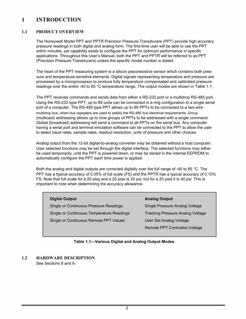
The heart of the PPT measuring system is a silicon piezoresistive sensor which contains both pres- sure and temperature-sensitive elements. Digital signals representing temperature and pressure are processed by a microprocessor to produce fully temperature compensated and calibrated pressure readings over the entire -40 to 85 °C temperature range. The output modes are shown in Table 1.1.
The PPT receives commands and sends data from either a RS-232 port or a multidrop RS-485 port. Using the RS-232 type PPT, up to 89 units can be connected in a ring configuration to a single serial port of a computer. The RS-485 type PPT allows up to 89 PPTs to be connected to a two-wire multidrop bus, when bus repeaters are used to satisfy the RS-485 bus electrical requirements. Group (multicast) addressing allows up to nine groups of PPTs to be addressed with a single command. Global (broadcast) addressing will send a command to all PPTs on the serial bus. Any computer having a serial port and terminal emulation software can be connected to the PPT to allow the user to select baud rates, sample rates, readout resolution, units of pressure and other choices.
Analog output from the 12-bit digital-to-analog converter may be obtained without a host computer. User selected functions may be set through the digital interface. The selected functions may either be used temporarily, until the PPT is powered down, or may be stored in the internal EEPROM to automatically configure the PPT each time power is applied.
Both the analog and digital outputs are corrected digitally over the full range of -40 to 85 °C. The PPT has a typical accuracy of 0.05% of full scale (FS) and the PPTR has a typical accuracy of 0.10% FS. Note that full scale for a 20 psig and a 20 psia is 20 psi, but for a 20 psid it is 40 psi. This is important to note when determining the accuracy allowance.
Digital Output
Single or Continuous Pressure Readings
Single or Continuous Temperature Readings
Single or Continuous Remote PPT Values
Analog Output
Single Pressure Analog Voltage
Tracking Pressure Analog Voltage
User Set Analog Voltage
Remote PPT Controlled Voltage Table 1.1—Various Digital and Analog Output Modes
1.2 HARDWARE DESCRIPTION See Sections 8 and 9.
2
2 GETTING STARTED
2.1 OVERVIEW The first-time user should approach the PPT in a manner analogous to using a word processor program; i.e., many features are available but one may begin by using those of interest at the mo- ment. Section 2.7 of this manual lists command features by functional groups to assist in this selec- tion. When shipped from the factory, the default settings provide a pressure transducer that will be usable for many applications. Once the user is familiar with the performance and command struc- ture, changes may be made and stored using the ‘Store Parameters’ (SP) command. Once stored, the new default settings are activated each time the PPT is powered up. This tailors the personality of the PPT to meet the needs of a particular application.
2.2 EQUIPMENT NEEDED
To prepare the PPT for operation, three items are needed:
• A mating connector with proper wiring connections (see connector part number and wiring diagram in Section 6—Electrical Connections);
• A DC power supply;
• A source of pressure that is properly matched to the range and type of the PPT.
To operate the PPT in the analog output mode, one additional item is needed:
• Voltage Output - A five digit voltmeter with 0-5 volt range connected between Analog Out and Signal Common. A computer is not required when operating in this mode.
To operate the PPT in the digital output mode, one additional item is needed:
• A computer, or host processor, having an RS-232 or RS-485 serial port and terminal program software such as PROCOM™, VERSATERM™, TERMINAL (Windows® 3.x) or HYPERTERMINAL (Windows® 95). These programs are normally used to interface to a modem. The wiring diagram designates which PPT pins must connect to the computer “send”, “receive” and “common” pins for proper communications. Some computers may not have an RS-232 or RS- 485 serial port connection identical to the one shown in Section 6, making it necessary to adapt the PPT connections to that particular computer.
2.3 TERMINAL PROGRAM SETTINGS
• Enter the following settings in the terminal program:
Baud Rate .... 9600
Start Bits .... 1
Data Bits .... 8
Stop Bits .... 1
Parity .... None
• Attach a line feed to the carriage return.
• Turn the local echo ON. When shipped from the factory, the PPT is set to a baud rate of 9600, 1 start bit, 8 data bits with no parity and one stop bit. If the baud rate has been subsequently changed, and is unknown, it will be necessary to search all baud rate values to reestablish communication. See the BP command descrip- tion in Section 5.10 of this manual for possible settings.
3
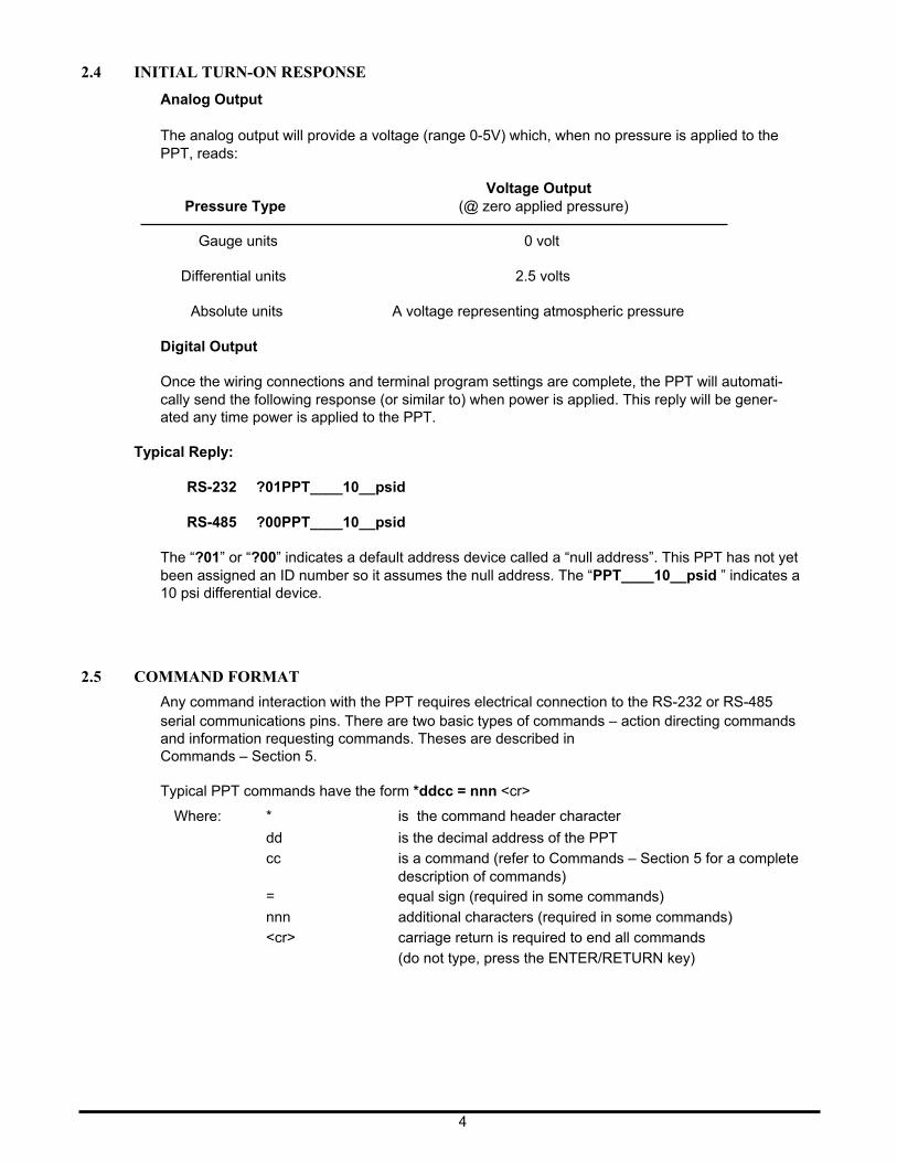
2.4 INITIAL TURN-ON RESPONSE
Analog Output
The analog output will provide a voltage (range 0-5V) which, when no pressure is applied to the PPT, reads:
Voltage Output Pressure Type
Gauge units
Differential units
Absolute units
Digital Output
(@ zero applied pressure)
0 volt
2.5 volts
A voltage representing atmospheric pressure
Once the wiring connections and terminal program settings are complete, the PPT will automati- cally send the following response (or similar to) when power is applied. This reply will be gener- ated any time power is applied to the PPT.
Typical Reply:
RS-232 ?01PPT____10__psid
RS-485 ?00PPT____10__psid
The “?01” or “?00” indicates a default address device called a “null address”. This PPT has not yet been assigned an ID number so it assumes the null address. The “PPT____10__psid ” indicates a 10 psi differential device.
2.5 COMMAND FORMAT
Any command interaction with the PPT requires electrical connection to the RS-232 or RS-485 serial communications pins. There are two basic types of commands – action directing commands and information requesting commands. Theses are described in Commands – Section 5.
Typical PPT commands have the form *ddcc = nnn <cr>
Where: *
dd
cc
=
nnn
<cr>
is the command header character
is the decimal address of the PPT
is a command (refer to Commands – Section 5 for a complete description of commands) equal sign (required in some commands)
additional characters (required in some commands)
carriage return is required to end all commands
(do not type, press the ENTER/RETURN key)
4
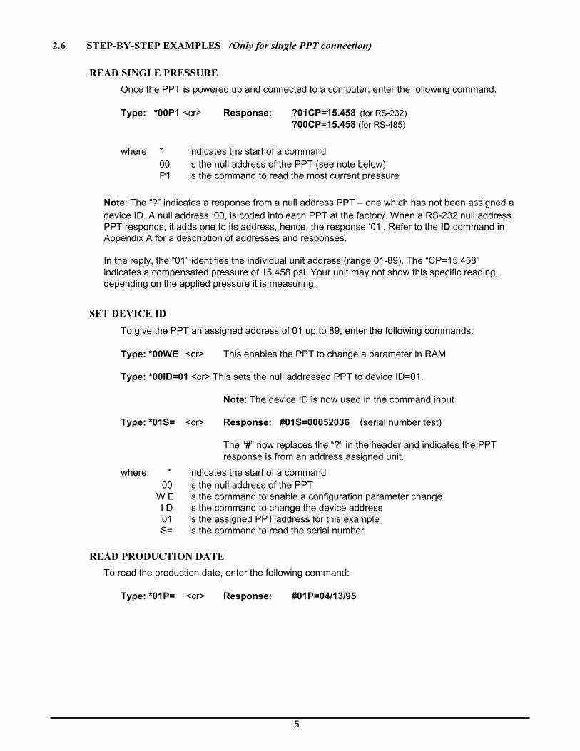
2.6 STEP-BY-STEP EXAMPLES (Only for single PPT connection)
READ SINGLE PRESSURE
Once the PPT is powered up and connected to a computer, enter the following command:
Type: *00P1 <cr> Response: ?01CP=15.458 (for RS-232) ?00CP=15.458 (for RS-485)
where *
indicates the start of a command 00 is the null address of the PPT (see note below) P1 is the command to read the most current pressure
Note: The “?” indicates a response from a null address PPT – one which has not been assigned a device ID. A null address, 00, is coded into each PPT at the factory. When a RS-232 null address PPT responds, it adds one to its address, hence, the response ‘01’. Refer to the ID command in Appendix A for a description of addresses and responses.
In the reply, the “01” identifies the individual unit address (range 01-89). The “CP=15.458” indicates a compensated pressure of 15.458 psi. Your unit may not show this specific reading, depending on the applied pressure it is measuring.
SET DEVICE ID
To give the PPT an assigned address of 01 up to 89, enter the following commands:
Type: *00WE <cr> This enables the PPT to change a parameter in RAM
Type: *00ID=01 <cr> This sets the null addressed PPT to device ID=01.
Note: The device ID is now used in the command input
Type: *01S= <cr> Response: #01S=00052036 (serial number test)
The “#” now replaces the “?” in the header and indicates the PPT response is from an address assigned unit.
where: * indicates the start of a command 00 is the null address of the PPT
W E is the command to enable a configuration parameter change I D is the command to change the device address 01 is the assigned PPT address for this example S= is the command to read the serial number
READ PRODUCTION DATE
To read the production date, enter the following command:
Type: *01P= <cr> Response: #01P=04/13/95
5
READ CONTINUOUS PRESSURE
For continuous pressure readings at the factory set default rate of 5 per second, enter the follow- ing command:
Type: *01P2 <cr> This enables a continuous stream of compensated pressure readings to flow into the terminal program.
Type: $*99IN <cr> This is the best way to stop the continuous pressure reading com- mands. The ‘$’ character temporarily stops, or suspends, either the continuous pressure or temperature readings. The *99IN command stops the continuous pressure readings.
CHANGE TO A NEW SAMPLE RATE
Enter the following command:
Type: *01WE <cr> This enables the PPT RAM to accept a changed parameter.
Type: *01I=M20<cr> This sets the integration time to value 20, which corresponds to an output sample every 2 seconds.
The sample rate will change to one every 2 seconds. I= is an abbreviation for Integration time which determines how long to accumulate pressure samples between readings. Each integration period gathers the data for one pressure reading output (see Section 4.2 What is integration?). The range of integration times can be set by specifying readings per second (I=R45 for 45 read- ings/sec) or time delay in 100 millisecond intervals (I=M60 for 6 seconds). The factory set inte- gration time is 5 samples per second (I=M2).
The output data rate can also be altered by use of the idle count (IC) command or by changing the reading rate (RR) command in conjunction with the operating mode (OP) command. See Section 4 for description of these commands.
REPEAT THE READ CONTINUOUS PRESSURE STEP ABOVE
Notice the slower output rate of one sample every 2 seconds.
TRY OTHER COMMANDS
Experiment with other commands to become familiar with the command structures. A short overview of each command with input and response examples is shown in Section 3 Commands – Quick Reference. See Section 5—Commands for complete command descriptions. Until an SP=ALL command is executed, no changes will be stored in the EEPROM. Re-apply the power or send an IN=RESET command to revert to EEPROM default settings.
6
2.7 COMMAND FUNCTIONAL GROUPS
PRESSURE DISPLAY UNITS PPT reads out psi, in wc, mm Hg, etc. D U Set pressure units for output readings—any one of 13 common units U = Specify a user supplied unit of measure
TEMPERATURE T1 Single °C T2 Continuous °C T3 Single °F T4 Continuous °F
RS-232/RS-485 BUS PARAMETERS BP Changes baud rate and parity I D Assign device ID and group addresses
M = Select alternate message Headers [RS-485 only] SI Synchronize Integration cycles among units [RS-485 only]
TO Set Transceiver Operating parameters
OUTPUT READING AND RATE Speed up or slow down output rate
Single Reading Commands
P1 Single RS-232 pressure reading...ASCII format P3 Single RS-232 pressure reading...binary format T1 Single RS-232 temperature reading...°C T3 Single RS-232 temperature reading...°F
Continuous Readings Commands
P2 Continuous RS-232 pressure readings...ASCII format P4 Continuous RS-232 pressure readings...binary format T2 Continuous RS-232 temperature readings...°C T4 Continuous RS-232 temperature readings...°F
Integration Time Commands —Changes pressure reading response time
DS Set deadband and sensitivity parameters I = Set pressure integration time, and reading rate S2 Set threshold level for 2X speed shift S5 Set threshold level for output within any 50 msec period SI Synchronize pressure Integration cycles
Idle Count Command —Changes pressure reading response time
I C Set number of idle integration cycles
Reading Response To Changes In Input Pressure—Filters small changes
S2 Set threshold level for 2X speed shift S5 Set threshold level for output within any 50 msec period RR Set number of identical readings to skip OP Transmit all readings or only changed readings
FORMAT PRESSURE READINGS—Changes data length into host processor
Binary Format Commands
P3 Single RS-232 pressure...binary format P4 Continuous RS-232 pressure...binary format OP Set operating mode...binary format checksum...set signed or extended binary output
format
ASCII Format Commands
All readings, except P3, P4 and ~, are ASCII format readings. OP Set operating mode...all readings or only changed readings
7
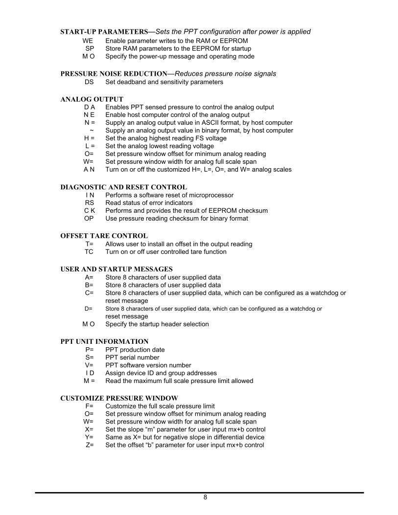
START-UP PARAMETERS—Sets the PPT configuration after power is applied WE Enable parameter writes to the RAM or EEPROM
SP Store RAM parameters to the EEPROM for startup M O Specify the power-up message and operating mode
PRESSURE NOISE REDUCTION—Reduces pressure noise signals DS Set deadband and sensitivity parameters
ANALOG OUTPUT D A Enables PPT sensed pressure to control the analog output N E Enable host computer control of the analog output N = Supply an analog output value in ASCII format, by host computer
~ Supply an analog output value in binary format, by host computer H = Set the analog highest reading FS voltage L = Set the analog lowest reading voltage O= Set pressure window offset for minimum analog reading W= Set pressure window width for analog full scale span A N Turn on or off the customized H=, L=, O=, and W= analog scales
DIAGNOSTIC AND RESET CONTROL I N Performs a software reset of microprocessor RS Read status of error indicators C K Performs and provides the result of EEPROM checksum OP Use pressure reading checksum for binary format
OFFSET TARE CONTROL T= Allows user to install an offset in the output reading TC Turn on or off user controlled tare function
USER AND STARTUP MESSAGES A= Store 8 characters of user supplied data B= Store 8 characters of user supplied data C= Store 8 characters of user supplied data, which can be configured as a watchdog or
reset message D= Store 8 characters of user supplied data, which can be configured as a watchdog or
reset message M O Specify the startup header selection
PPT UNIT INFORMATION P= PPT production date S= PPT serial number V= PPT software version number I D Assign device ID and group addresses
M = Read the maximum full scale pressure limit allowed
CUSTOMIZE PRESSURE WINDOW F= Customize the full scale pressure limit O= Set pressure window offset for minimum analog reading W= Set pressure window width for analog full scale span X= Set the slope “m” parameter for user input mx+b control Y= Same as X= but for negative slope in differential device Z= Set the offset “b” parameter for user input mx+b control
8
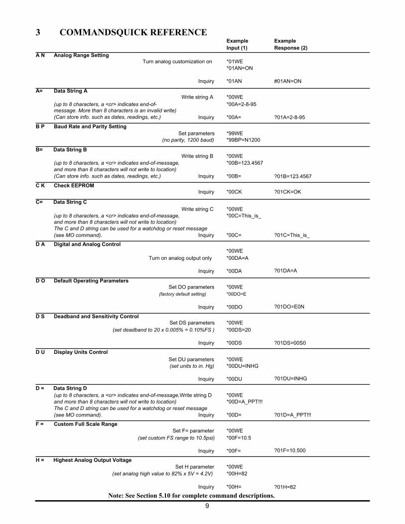
3 COMMANDSQUICK REFERENCE Example Input (1)
Example Response (2)
A N Analog Range Setting A= Data String A
Turn analog customization on *01WE
*01AN=ON Inquiry *01AN
Write string A *00WE
#01AN=ON
(up to 8 characters, a <cr> indicates end-of- message. More than 8 characters is an invalid write) (Can store info. such as dates, readings, etc.)
B P Baud Rate and Parity Setting
*00A=2-8-95 Inquiry *00A=
?01A=2-8-95
B= Data String B
Set parameters *99WE (no parity, 1200 baud) *99BP=N1200
Write string B *00WE (up to 8 characters, a <cr> indicates end-of-message, and more than 8 characters will not write to location) (Can store info. such as dates, readings, etc.)
C K Check EEPROM
C= Data String C
*00B=123.4567 Inquiry *00B=
Inquiry *00CK
?01B=123.4567
?01CK=OK
Write string C *00WE (up to 8 characters, a <cr> indicates end-of-message, and more than 8 characters will not write to location) The C and D string can be used for a watchdog or reset message
*00C=This_is_
(see MO command).
D A Digital and Analog Control
D O Default Operating Parameters
Inquiry *00C=
*00WE Turn on analog output only *00DA=A
Inquiry *00DA
Set DO parameters *00WE (factory default setting) *00DO=E
Inquiry *00DO
?01C=This_is_ ?01DA=A ?01DO=E0N
D S Deadband and Sensitivity Control
Set DS parameters *00WE (set deadband to 20 x 0.005% = 0.10%FS ) *00DS=20
Inquiry *00DS
D U Display Units Control Set DU parameters *00WE (set units to in. Hg) *00DU=INHG
Inquiry *00DU
D = Data String D (up to 8 characters, a <cr> indicates end-of-message,Write string D *00WE and more than 8 characters will not write to location) *00D=A_PPT!!! The C and D string can be used for a watchdog or reset message
?01DS=00S0 ?01DU=INHG
(see MO command).
F = Custom Full Scale Range
Inquiry *00D=
Set F= parameter *00WE (set custom FS range to 10.5psi) *00F=10.5
Inquiry *00F=
?01D=A_PPT!!! ?01F=10.500
H = Highest Analog Output Voltage
Set H parameter *00WE (set analog high value to 82% x 5V = 4.2V) *00H=82
Inquiry *00H=
?01H=82
Note: See Section 5.10 for complete command descriptions.
9
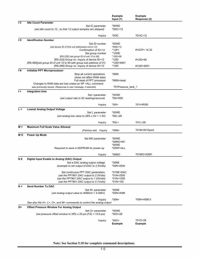
I C Idle Count Parameter
Example Input (1)
Set IC parameter *00WE
Example Response (2)
(set idle count to 12 , so that 12 output samples are skipped) *00IC=12 Inquiry *00IC
I D Identification Number Set ID number *00WE
(set device ID of first null addressed unit to 12) *00ID=12
Confirmation of ID=12 *12P1 Set group number *12WE
[RS-232] (set group ID of unit 12 to 95) *12ID=95
[RS-232] Group no. inquiry of device ID=12 *12ID [RS-485](set group ID of unit 12 to 95 with group sub-address of 01) *12ID=9501
[RS-485] Group no. inquiry of device ID=12 *12ID
I N Initialize PPT Microprocessor Stop all current operations *99IN (does not affect RAM data) Full reset of PPT processor *99IN=reset
Changes to RAM data are lost unless an SP =ALL command
?01IC=12 #12CP= 14.32 #12ID=95 #12ID=9501
was previously issued. (Response is user message, if selected) ?01Pressure_tank_1
I = Integration time Set I parameter *00WE
(set output rate to 50 readings/second) *00I=R50
L = Lowest Analog Output Voltage
Inquiry *00I=
Set L parameter *00WE
?01I=R050
(set analog low value to 28% x 5V = 1.4V) *00L=28 Inquiry *00L=
M = Maximum Full Scale Value Allowed (Factory set) Inquiry *00M=
M O Power Up Mode Set MO parameter *00WE
*00MO=M1 *00WE
Required to save in EEPROM for power-up *00SP=ALL Inquiry *00MO
N E Digital Input Enable to Analog (DAC) Output Set a DAC analog output voltage *00NE
(example to set output of DAC to 2.5Volts) *00N=2500 Set continuous PPT DAC parameters *01NE=DAC
(set the PPT#01 DAC output to 2.5Volts) *01N=2500 (set the PPT#01 DAC output to 1.25Volts) *01N=1250 (set the PPT#01 DAC output to 0.1Volts) *01N=100
N = Send Number To DAC Set N= parameter *00NE
(set analog output value to 4096mV = 4.096V) *00N=4096 Inquiry *00N=
See also the H=, L=, O=, and W= commands to control the analog output
O= Offset Pressure Window For Analog Output Set O= parameter *00WE
(set pressure offset window to 28% x 20 psi (FS) = 15.6 psi) *00O=28 Inquiry *00O=
Example
?01L=28
?01M=0010psid
?01MO=X2M1 ?00N=4096.0 ?01O=28 Example
Note: See Section 5.10 for complete command descriptions.
1 0
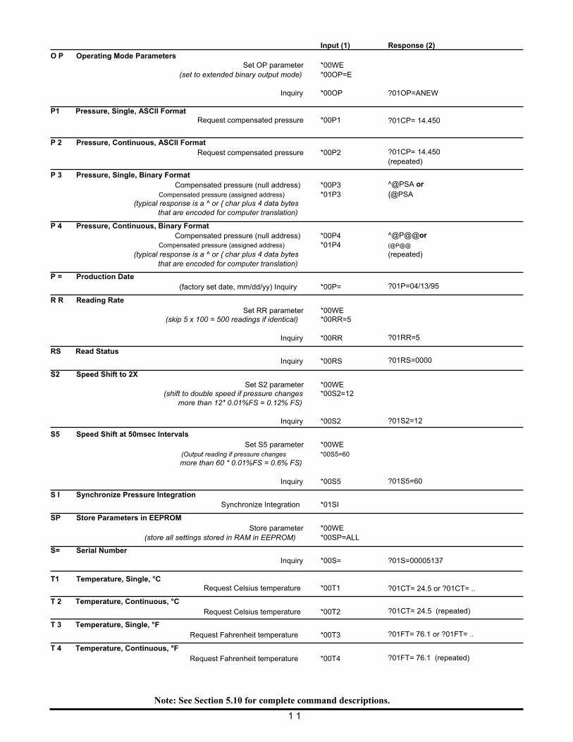
O P Operating Mode Parameters
Input (1)
Set OP parameter *00WE
Response (2)
(set to extended binary output mode) *00OP=E Inquiry *00OP
P1 Pressure, Single, ASCII Format
Request compensated pressure *00P1
P 2 Pressure, Continuous, ASCII Format Request compensated pressure *00P2
P 3 Pressure, Single, Binary Format Compensated pressure (null address) *00P3
Compensated pressure (assigned address) *01P3 (typical response is a ^ or { char plus 4 data bytes
that are encoded for computer translation)
P 4 Pressure, Continuous, Binary Format Compensated pressure (null address) *00P4
Compensated pressure (assigned address) *01P4 (typical response is a ^ or { char plus 4 data bytes
that are encoded for computer translation)
P = Production Date (factory set date, mm/dd/yy) Inquiry *00P=
R R Reading Rate Set RR parameter *00WE
(skip 5 x 100 = 500 readings if identical) *00RR=5 Inquiry *00RR
RS Read Status Inquiry *00RS
S2 Speed Shift to 2X Set S2 parameter *00WE
(shift to double speed if pressure changes *00S2=12 more than 12* 0.01%FS = 0.12% FS)
Inquiry *00S2
S5 Speed Shift at 50msec Intervals Set S5 parameter *00WE
(Output reading if pressure changes *00S5=60 more than 60 * 0.01%FS = 0.6% FS)
Inquiry *00S5
S I Synchronize Pressure Integration Synchronize Integration *01SI
SP Store Parameters in EEPROM Store parameter *00WE
(store all settings stored in RAM in EEPROM) *00SP=ALL
S= Serial Number Inquiry *00S=
T1 Temperature, Single, °C
Request Celsius temperature *00T1
T 2 Temperature, Continuous, °C Request Celsius temperature *00T2
T 3 Temperature, Single, °F Request Fahrenheit temperature *00T3
T 4 Temperature, Continuous, °F Request Fahrenheit temperature *00T4
?01OP=ANEW ?01CP= 14.450
?01CP= 14.450 (repeated)
^@PSA or {@PSA ^@P@@or {@P@@
(repeated)
?01P=04/13/95
?01RR=5
?01RS=0000
?01S2=12 ?01S5=60 ?01S=00005137 ?01CT= 24.5 or ?01CT= ..
?01CT= 24.5 (repeated)
?01FT= 76.1 or ?01FT= ..
?01FT= 76.1 (repeated)
Note: See Section 5.10 for complete command descriptions.
1 1
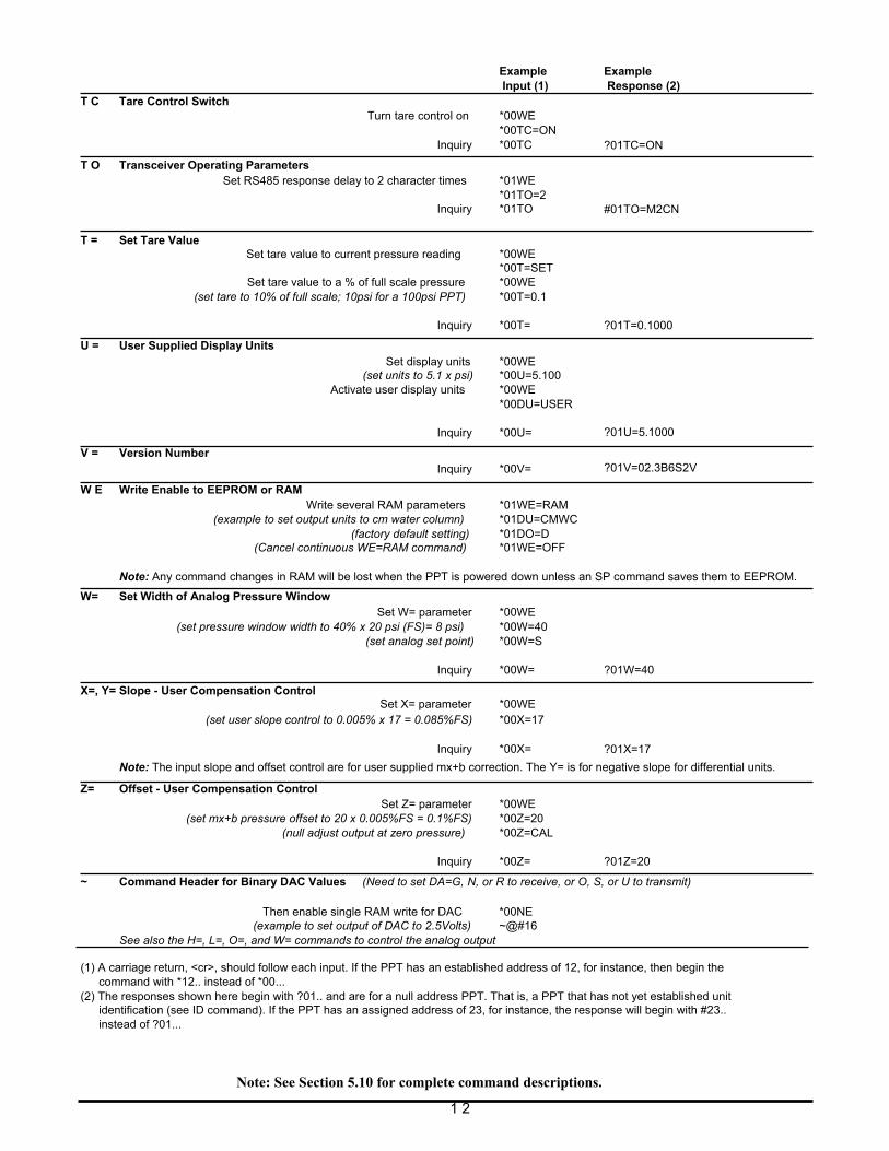
T C Tare Control Switch T O Transceiver Operating Parameters
Example Input (1)
Turn tare control on *00WE
*00TC=ON Inquiry *00TC
Example Response (2) ?01TC=ON
T = Set Tare Value
Set RS485 response delay to 2 character times *01WE *01TO=2
Inquiry *01TO Set tare value to current pressure reading *00WE
*00T=SET Set tare value to a % of full scale pressure *00WE
#01TO=M2CN
(set tare to 10% of full scale; 10psi for a 100psi PPT) *00T=0.1 Inquiry *00T=
U = User Supplied Display Units Set display units *00WE
(set units to 5.1 x psi) *00U=5.100 Activate user display units *00WE
*00DU=USER Inquiry *00U=
V = Version Number Inquiry *00V=
W E Write Enable to EEPROM or RAM Write several RAM parameters *01WE=RAM
(example to set output units to cm water column) *01DU=CMWC (factory default setting) *01DO=D
(Cancel continuous WE=RAM command) *01WE=OFF
?01T=0.1000 ?01U=5.1000
?01V=02.3B6S2V
Note: Any command changes in RAM will be lost when the PPT is powered down unless an SP command saves them to EEPROM.
W= Set Width of Analog Pressure Window Set W= parameter *00WE
(set pressure window width to 40% x 20 psi (FS)= 8 psi) *00W=40 (set analog set point) *00W=S
X=, Y= Slope - User Compensation Control
Inquiry *00W=
Set X= parameter *00WE
?01W=40
(set user slope control to 0.005% x 17 = 0.085%FS) *00X=17 Inquiry *00X=
?01X=17
Note: The input slope and offset control are for user supplied mx+b correction. The Y= is for negative slope for differential units.
Z= Offset - User Compensation Control Set Z= parameter *00WE
(set mx+b pressure offset to 20 x 0.005%FS = 0.1%FS) *00Z=20 (null adjust output at zero pressure) *00Z=CAL
Inquiry *00Z=
?01Z=20
~ Command Header for Binary DAC Values (Need to set DA=G, N, or R to receive, or O, S, or U to transmit)
Then enable single RAM write for DAC *00NE
(example to set output of DAC to 2.5Volts) ~@#16 See also the H=, L=, O=, and W= commands to control the analog output
(1) A carriage return, <cr>, should follow each input. If the PPT has an established address of 12, for instance, then begin the command with *12.. instead of *00...
(2) The responses shown here begin with ?01.. and are for a null address PPT. That is, a PPT that has not yet established unit identification (see ID command). If the PPT has an assigned address of 23, for instance, the response will begin with #23.. instead of ?01...
Note: See Section 5.10 for complete command descriptions.
1 2
4 FUNCTIONAL OPERATION
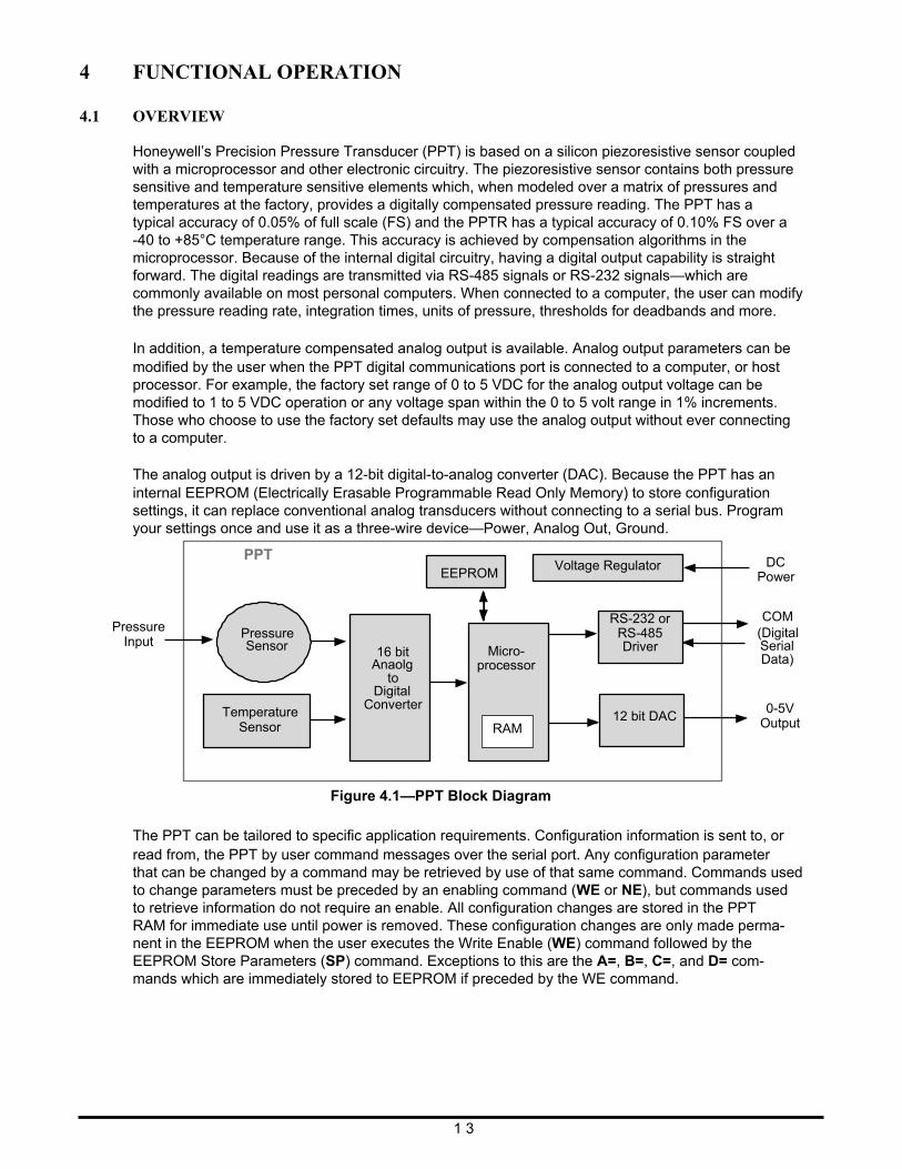
4.1 OVERVIEW Honeywell’s Precision Pressure Transducer (PPT) is based on a silicon piezoresistive sensor coupled with a microprocessor and other electronic circuitry. The piezoresistive sensor contains both pressure sensitive and temperature sensitive elements which, when modeled over a matrix of pressures and temperatures at the factory, provides a digitally compensated pressure reading. The PPT has a typical accuracy of 0.05% of full scale (FS) and the PPTR has a typical accuracy of 0.10% FS over a -40 to +85°C temperature range. This accuracy is achieved by compensation algorithms in the microprocessor. Because of the internal digital circuitry, having a digital output capability is straight forward. The digital readings are transmitted via RS-485 signals or RS-232 signals—which are commonly available on most personal computers. When connected to a computer, the user can modify the pressure reading rate, integration times, units of pressure, thresholds for deadbands and more.
In addition, a temperature compensated analog output is available. Analog output parameters can be modified by the user when the PPT digital communications port is connected to a computer, or host processor. For example, the factory set range of 0 to 5 VDC for the analog output voltage can be modified to 1 to 5 VDC operation or any voltage span within the 0 to 5 volt range in 1% increments. Those who choose to use the factory set defaults may use the analog output without ever connecting to a computer. The analog output is driven by a 12-bit digital-to-analog converter (DAC). Because the PPT has an internal EEPROM (Electrically Erasable Programmable Read Only Memory) to store configuration settings, it can replace conventional analog transducers without connecting to a serial bus. Program your settings once and use it as a three-wire device—Power, Analog Out, Ground.
Pressure Input
PPT Pressure Sensor
Temperature Sensor
16 bit
Anaolg to
Digital Converter
EEPROM
Micro-
processor RAM
Voltage Regulator
RS-232 or RS-485 Driver
12 bit DAC
DC
Power
COM (Digital Serial Data) 0-5V
Output
Figure 4.1—PPT Block Diagram
The PPT can be tailored to specific application requirements. Configuration information is sent to, or read from, the PPT by user command messages over the serial port. Any configuration parameter that can be changed by a command may be retrieved by use of that same command. Commands used to change parameters must be preceded by an enabling command (WE or NE), but commands used to retrieve information do not require an enable. All configuration changes are stored in the PPT RAM for immediate use until power is removed. These configuration changes are only made perma- nent in the EEPROM when the user executes the Write Enable (WE) command followed by the EEPROM Store Parameters (SP) command. Exceptions to this are the A=, B=, C=, and D= com- mands which are immediately stored to EEPROM if preceded by the WE command.
1 3
4.2 WHAT IS INTEGRATION?
The input pressure is converted to an analog electrical signal at the pressure sensor. This signal feeds into a delta-sigma analog-to-digital (A/D) converter where it is changed into a digital signal representing the pressure value. During the A/D conversion cycle, the signal is integrated over time. That is, the pressure reading is averaged (integrated) over the A/D conversion cycle so the resultant digital value is the summation of the average pressures observed during the cycle. This conversion cycle is controlled by the user with the Deadband and Sensitivity (DS), Synchronization Integration (SI), Idle Count (IC), and Integration (I=) commands.
4.3 PRESSURE READING CONTROL The PPT commands allow considerable flexibility in tailoring pressure acquisition times, sample windows, thresholds, and output rates. These are controlled by 7 commands: Deadband and Sensitiv- ity (DS), Integration (I=), Speed shift (S2), Speed shift at 50msec intervals (S5), Idle Count (IC), Reading Rate (RR), and OPerating mode (OP). Figure 4.2 illustrates how the user may control these attributes in three ways:
First, the internal analog-to-digital converter integration time may be controlled over a range of 1 sample every 12 seconds up to 120 samples per second. This is controlled using the ‘Integration’ (I=) command. The integration time is used to control the A/D integration cycle that allow noisy pressure inputs to be filtered, or averaged, over a selected period of time. See Figures 4.12and 4.13. The integration time can be set within a range of 1 to 120 samples/sec using the I=Rn form or a range of 100msec to 12 sec/sample using the I=Mn form. The values for ‘n’ range from 1 to 120 for both the rate (Rn) form and the millisecond (Mn) form.
The speed shift commands can only be enabled when the integration time is set using the I=Mn form. When enabled, the thresholds for pressure change can be set that cause the output rate to double (S2) or update at 50 msec intervals (S5). When the change of input pressure reaches or exceeds the threshold, the sample rate shifts to the higher rate.
Second, the integration cycles may be spaced with idle periods that cause pressure reading times to increase to as often as one every 51 minutes. The Idle Count (IC) command will insert, or skip, from 0 to 255 idle periods equal to the integration time. If the integration time is set to the maximum, 12 sec/sample, and an idle count of 255 is selected, then the time between samples = 12 sec. x 256 = 51.2 minutes.
Third, the reading rate may be controlled so pressure readings are obtained only when pressure changes occur. The Reading Rate (RR) command can be set to output only changed readings, or skip from 100 to 1000 identical readings. The Operating Mode command (OP) can be set to output every reading or to only output changes. The Deadband setting in the DS command can filter a small pressure change by not allowing the pressure reading to vary as long as it remains within the deadband limits. This controls the sensitivity to change of the RR and OP command modes when the ‘output only when pressure changes’ options are selected. If the pressure signal is stable within the deadband limit, then the pressure reading time can be increased up to 1000 times the integration time by using the RR command.
1 4
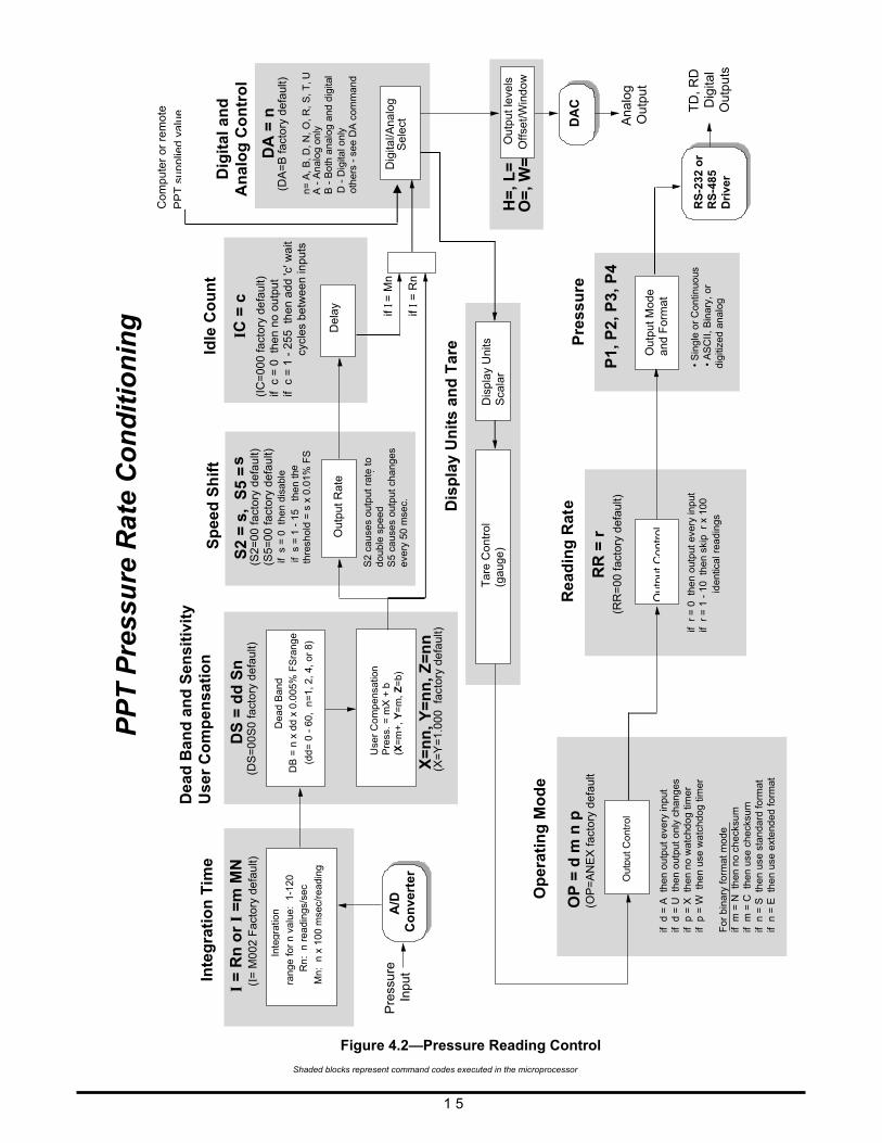
Figure 4.2—Pressure Reading Control
Shaded blocks represent command codes executed in the microprocessor
1 5
S2
= s
, S
5 =
s (S
2=00
fact
ory
def
ault)
(S5=
00 fa
ctor
y d
efau
lt) if
s =
0 t
hen
disa
ble
if s
= 1
- 1
5 t
hen
th e
thre
shol
d =
s x
0.0
1% F
S
Out
put
Rat
e
Sp
eed
Sh
ift
.
• S
ingl
e or
Con
tinuo
u s
• A
SC
II, B
inar
y, o
rdi
gitiz
ed a
nalo
g
P1,
P2,
P3,
P4
Pre
ssu
re
Del
ay
IC
= c
Idle
Co
un
t
if r
= 0
the
n ou
tput
eve
ry in
put
if r
= 1
- 1
0 t
hen
skip
r x
100
id
entic
al r
eadi
ngs
RR
= r
(R
R=
00 f
acto
ry d
efau
lt)
Rea
din
g R
at e
Op
erat
ing
Mo
de
PP
T P
ress
ure
Rat
e C
on
dit
ion
ing
DS
= d
d S
n
(DS
=00
S0
fact
ory
def
ault)
Pre
ssur
e In
put
DA
= n
(DA
=B
fact
ory
def
ault)
n=
A, B
, D, N
, O
, R,
S, T
, U A
- A
nalo
g on
ly B
- B
oth
anal
og a
nd d
igita
l D
- D
igita
l onl
y o
ther
s -
see
DA
com
man
d
Com
pute
r or
re
mot
e TD
, RD
D
igita
l O
utpu
ts
rang
e fo
r n
valu
e: 1
-120
R
n: n
rea
ding
s/se
c
Mn:
n x
100
mse
c/re
adin
g
Inte
gra
tio
n T
ime
if I
= R
n
if I
= M
n
DA
C
Ana
log
Out
put
A/D
Co
nve
rte
r
Dea
d B
and
DB
= n
x d
d x
0.00
5% F
Sra
nge
(dd=
0 -
60,
n=
1, 2
, 4,
or
8)
X=
nn
, Y=
nn
, Z=
nn
(X=
Y=
1.00
0 fa
ctor
y de
faul
t) D
isp
lay
Un
its
and
Tar
e
Dig
ital/A
nalo
g S
ele
ct
Out
put l
evel
s O
ffset
/Win
dow
H
=, L
= O
=, W
=
Inte
grat
ion
Out
put C
ontr
ol
PP
Tsu
pplie
dva
lue
Dig
ital
an
d
An
alo
g C
on
tro
l
S2
caus
es o
utpu
t ra
te to
do
uble
spe
ed
S5
caus
es o
utpu
t cha
nges
ev
ery
50 m
sec.
Dis
pla
y U
nits
S
cala
r T
are
Con
trol
(g
auge
)
Out
put
Con
trol
Out
put M
ode
and
For
mat
RS
-232
or
R
S-4
85
Dri
ver
Dea
d B
and
an
d S
ensi
tivi
ty
Use
r C
om
pen
sati
on
Use
r C
ompe
nsat
ion
Pre
ss. =
mX
+ b
(X
=m
+,
Y=
m,
Z=
b)
OP
= d
m n
p
(OP
=A
NE
X fa
cto
ry d
efau
lt
if d
= A
the
n ou
tput
eve
ry in
put
if d
= U
the
n ou
tput
onl
y ch
ange
s if
p =
X t
hen
no w
atch
dog
timer
if
p =
W t
hen
use
wat
chdo
g tim
er
For
bin
ary
form
at m
ode
if m
= N
the
n no
che
cksu
m
if m
= C
the
n us
e ch
ecks
um
if n
= S
the
n us
e st
anda
rd fo
rmat
if
n =
E t
hen
use
exte
nded
form
at
(I=
M00
2 F
acto
ry d
efau
lt)
I =
Rn
or
I =
m M
N
(IC
=00
0 fa
cto
ry d
efau
lt)
if c
= 0
the
n no
out
put
if
c =
1 -
255
th
en a
dd 'c
' wai
t
c
ycle
s be
twee
n in
puts
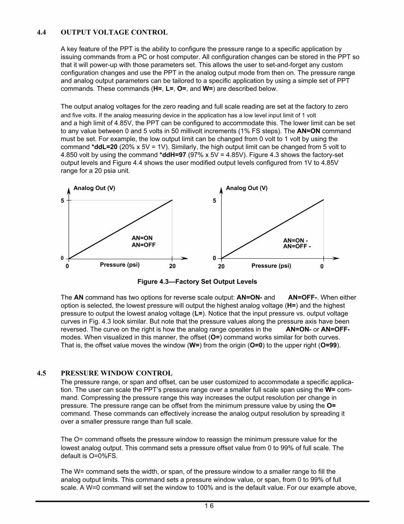
4.4 OUTPUT VOLTAGE CONTROL A key feature of the PPT is the ability to configure the pressure range to a specific application by issuing commands from a PC or host computer. All configuration changes can be stored in the PPT so that it will power-up with those parameters set. This allows the user to set-and-forget any custom configuration changes and use the PPT in the analog output mode from then on. The pressure range and analog output parameters can be tailored to a specific application by using a simple set of PPT commands. These commands (H=, L=, O=, and W=) are described below.
The output analog voltages for the zero reading and full scale reading are set at the factory to zero and five volts. If the analog measuring device in the application has a low level input limit of 1 volt and a high limit of 4.85V, the PPT can be configured to accommodate this. The lower limit can be set to any value between 0 and 5 volts in 50 millivolt increments (1% FS steps). The AN=ON command must be set. For example, the low output limit can be changed from 0 volt to 1 volt by using the command *ddL=20 (20% x 5V = 1V). Similarly, the high output limit can be changed from 5 volt to 4.850 volt by using the command *ddH=97 (97% x 5V = 4.85V). Figure 4.3 shows the factory-set output levels and Figure 4.4 shows the user modified output levels configured from 1V to 4.85V range for a 20 psia unit.
5 0
Analog Out (V)
AN=ON AN=OFF
5 0
Analog Out (V)
AN=ON - AN=OFF -
0 Pressure (psi) 20 20 Pressure (psi) 0 Figure 4.3—Factory Set Output Levels
The AN command has two options for reverse scale output: AN=ON- and AN=OFF-. When either option is selected, the lowest pressure will output the highest analog voltage (H=) and the highest pressure to output the lowest analog voltage (L=). Notice that the input pressure vs. output voltage curves in Fig. 4.3 look similar. But note that the pressure values along the pressure axis have been reversed. The curve on the right is how the analog range operates in the AN=ON- or AN=OFF- modes. When visualized in this manner, the offset (O=) command works similar for both curves. That is, the offset value moves the window (W=) from the origin (O=0) to the upper right (O=99).
4.5 PRESSURE WINDOW CONTROL The pressure range, or span and offset, can be user customized to accommodate a specific applica- tion. The user can scale the PPT’s pressure range over a smaller full scale span using the W= com- mand. Compressing the pressure range this way increases the output resolution per change in pressure. The pressure range can be offset from the minimum pressure value by using the O= command. These commands can effectively increase the analog output resolution by spreading it over a smaller pressure range than full scale.
The O= command offsets the pressure window to reassign the minimum pressure value for the lowest analog output. This command sets a pressure offset value from 0 to 99% of full scale. The default is O=0%FS.
The W= command sets the width, or span, of the pressure window to a smaller range to fill the analog output limits. This command sets a pressure window value, or span, from 0 to 99% of full scale. A W=0 command will set the window to 100% and is the default value. For our example above,
1 6
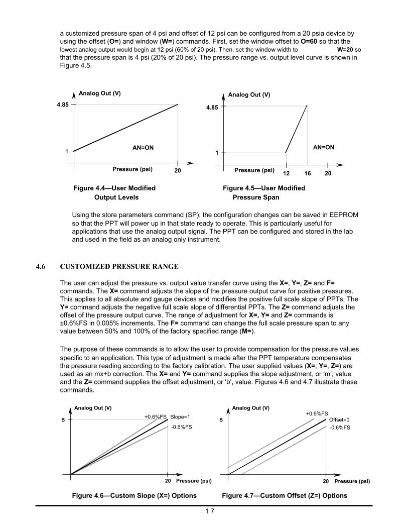
a customized pressure span of 4 psi and offset of 12 psi can be configured from a 20 psia device by using the offset (O=) and window (W=) commands. First, set the window offset to O=60 so that the lowest analog output would begin at 12 psi (60% of 20 psi). Then, set the window width to W=20 so that the pressure span is 4 psi (20% of 20 psi). The pressure range vs. output level curve is shown in Figure 4.5.
4.85
1
Analog Out (V)
AN=ON
4.85
1
Analog Out (V)
AN=ON
Pressure (psi)
20
Pressure (psi)
12
16
20
Figure 4.4—User Modified
Output Levels
Figure 4.5—User Modified
Pressure Span
Using the store parameters command (SP), the configuration changes can be saved in EEPROM so that the PPT will power up in that state ready to operate. This is particularly useful for applications that use the analog output signal. The PPT can be configured and stored in the lab and used in the field as an analog only instrument.
4.6 CUSTOMIZED PRESSURE RANGE The user can adjust the pressure vs. output value transfer curve using the X=, Y=, Z= and F= commands. The X= command adjusts the slope of the pressure output curve for positive pressures. This applies to all absolute and gauge devices and modifies the positive full scale slope of PPTs. The Y= command adjusts the negative full scale slope of differential PPTs. The Z= command adjusts the offset of the pressure output curve. The range of adjustment for X=, Y= and Z= commands is ±0.6%FS in 0.005% increments. The F= command can change the full scale pressure span to any value between 50% and 100% of the factory specified range (M=).
The purpose of these commands is to allow the user to provide compensation for the pressure values specific to an application. This type of adjustment is made after the PPT temperature compensates the pressure reading according to the factory calibration. The user supplied values (X=, Y=, Z=) are used as an mx+b correction. The X= and Y= command supplies the slope adjustment, or ‘m’, value and the Z= command supplies the offset adjustment, or ‘b’, value. Figures 4.6 and 4.7 illustrate these commands. 5
Analog Out (V)
+0.6%FS Slope=1
-0.6%FS
20 Pressure (psi)
5
Analog Out (V)
+0.6%FS Offset=0
-0.6%FS
20 Pressure (psi)
Figure 4.6—Custom Slope (X=) Options
1 7
Figure 4.7—Custom Offset (Z=) Options
The user compensated pressure output can be expressed in terms of X= and Y= slope values ‘m’ where m=0 to ±120. The offset value, Z=, can be expressed as ‘b’ where b=0 to ±120.
Pressure Output = [(1 + m x 0.00005) x Pressure Reading] + [(b x 0.00005) x (full scale)] The F= command is used in conjunction with the X=, Y=, and Z= command to customize the full scale range and user compensation of the PPT. The F= command allows the user to reduce the full scale range of the PPT as much as one-half the factory FS value. The F= command value can have up to 5 significant digits with a decimal point. Enter an F=0 command to disable this function and return to the factory default (M=) full scale value. Using the F= command, the maximum allowable full scale pressure is the M= value and the minimum allowable FS pressure is (0.5 x the M= value). The new F= value becomes the standard FS number used for other commands and range calcula- tions. Note that the accuracy specification is always referenced to the factory (M=) full scale value. For example, to customize the full scale range of a 20 psig (554 in. water column—inwc) device to 300 inwc, first select the desired display units using the DU command. Enter the command *ddWE followed by a *ddDU=INWC. Then enter a *ddWE followed by a *ddF=300. The full scale pressure for this unit is now 300 inwc.
4.7 SETTING ANALOG PRESSURE SET POINT
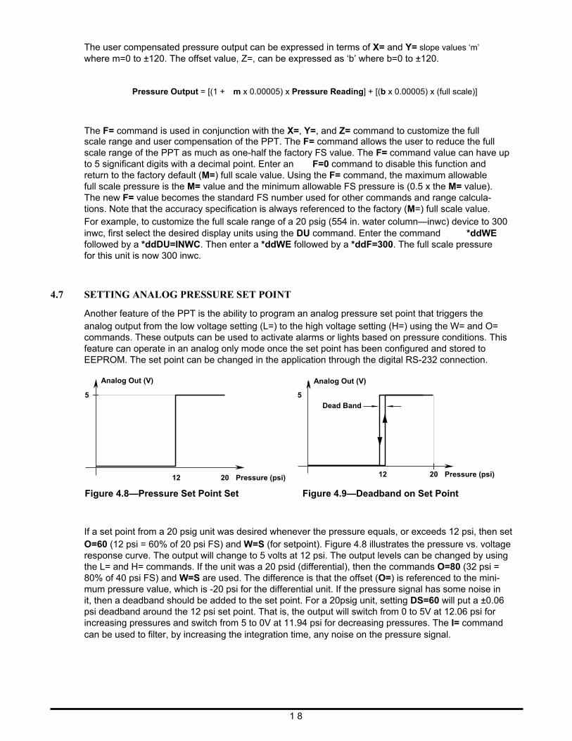
Another feature of the PPT is the ability to program an analog pressure set point that triggers the analog output from the low voltage setting (L=) to the high voltage setting (H=) using the W= and O= commands. These outputs can be used to activate alarms or lights based on pressure conditions. This feature can operate in an analog only mode once the set point has been configured and stored to EEPROM. The set point can be changed in the application through the digital RS-232 connection.
5
Analog Out (V)
12
20
Pressure (psi)
5
Analog Out (V)
Dead Band
12
20
Pressure (psi)
Figure 4.8—Pressure Set Point Set Figure 4.9—Deadband on Set Point
If a set point from a 20 psig unit was desired whenever the pressure equals, or exceeds 12 psi, then set O=60 (12 psi = 60% of 20 psi FS) and W=S (for setpoint). Figure 4.8 illustrates the pressure vs. voltage response curve. The output will change to 5 volts at 12 psi. The output levels can be changed by using the L= and H= commands. If the unit was a 20 psid (differential), then the commands O=80 (32 psi = 80% of 40 psi FS) and W=S are used. The difference is that the offset (O=) is referenced to the mini- mum pressure value, which is -20 psi for the differential unit. If the pressure signal has some noise in it, then a deadband should be added to the set point. For a 20psig unit, setting DS=60 will put a ±0.06 psi deadband around the 12 psi set point. That is, the output will switch from 0 to 5V at 12.06 psi for increasing pressures and switch from 5 to 0V at 11.94 psi for decreasing pressures. The I= command can be used to filter, by increasing the integration time, any noise on the pressure signal.
1 8
4.8 PPT ANALOG OUTPUT CONFIGURATIONS
The PPT is truly a smart sensor device, but it can also be used to replace conventional analog pres- sure sensors straight from the box. A benefit of using the PPT in the analog mode is that there is no need for offset or span adjustments to achieve the specified accuracy across a -40 to 85°C (-40 to 185°F) temperature range.
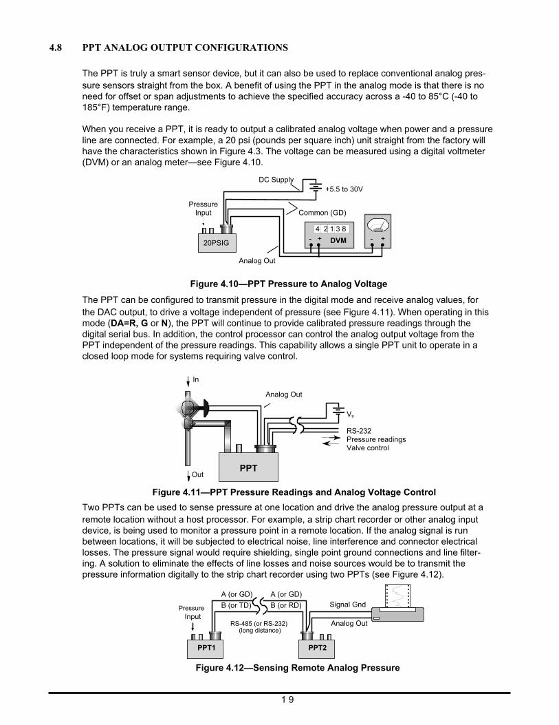
When you receive a PPT, it is ready to output a calibrated analog voltage when power and a pressure line are connected. For example, a 20 psi (pounds per square inch) unit straight from the factory will have the characteristics shown in Figure 4.3. The voltage can be measured using a digital voltmeter (DVM) or an analog meter—see Figure 4.10.
Figure 4.10—PPT Pressure to Analog Voltage
The PPT can be configured to transmit pressure in the digital mode and receive analog values, for the DAC output, to drive a voltage independent of pressure (see Figure 4.11). When operating in this mode (DA=R, G or N), the PPT will continue to provide calibrated pressure readings through the digital serial bus. In addition, the control processor can control the analog output voltage from the PPT independent of the pressure readings. This capability allows a single PPT unit to operate in a closed loop mode for systems requiring valve control.
Figure 4.11—PPT Pressure Readings and Analog Voltage Control
Two PPTs can be used to sense pressure at one location and drive the analog pressure output at a remote location without a host processor. For example, a strip chart recorder or other analog input device, is being used to monitor a pressure point in a remote location. If the analog signal is run between locations, it will be subjected to electrical noise, line interference and connector electrical losses. The pressure signal would require shielding, single point ground connections and line filter- ing. A solution to eliminate the effects of line losses and noise sources would be to transmit the pressure information digitally to the strip chart recorder using two PPTs (see Figure 4.12).
Pressure Input
A (or GD)
B (or TD)
A (or GD)
B (or RD)
Signal Gnd
PPT1
RS-485 (or RS-232) (long distance)
PPT2
Analog Out
Figure 4.12—Sensing Remote Analog Pressure
1 9
DC Supply
Pressure Input
+5.5 to 30V
Common (GD)
4 2 1 3 8
Analog Out
20PSIG - + - + DVM
In
Out PPT
Analog Out
Vs RS-232 Pressure readings Valve control
This can easily be accomplished using two PPT units, one at the pressure point and one by the chart recorder. A two-wire digital interface would transmit PPT1 pressure information to the PPT2 re- corder point. The digital RS-232, or RS-485, line is more tolerant of noisy environments and connec- tor losses than an anaolg signal. Commercially available RS-232, or RS-485, drivers and repeaters are available to extend the distance between the two PPT units, up to several miles if necessary. The PPT2 unit can be placed close to the chart recorder with very little, if any, noise on the analog output. When the RS-232, or RS-485, baud rate is set to 28,800 baud, the reading delay imposed by the digital transmission is 2 msec. The benefit of using two PPTs this way is that it is quick and easy to implement and that no software development is required. Using this technique, the RS-232 connections can be configured as a single two-wire bus that accommodates up to nine pairs of PPT units simultaneously sensing remote pressures. In order to avoid bus collisions on a RS-485 bus only one pair of PPTs may be operated in this mode. The PPT units should be configured as follows so that they will begin transmitting and outputting analog readings when power is applied (see Table 4.1). To connect additional PPT pairs to the RS-232 bus, configure each pair with a unique group number. Nine groups are available from number 90 through 98. The example shown in Table 4.1 assumes both PPT units are in the same group - factory default group is 90.
Commands to setup PPT1
Commands to setup PPT2
Input Comment Input Comment
*01WE=RAM Write enable *02WE Write enable
*01DA=U Pressure to ‘~’ format *02DA=R Digital to analog output
*01MO=P4 Power up mode *02NE=DAC Enable write to DAC
*01WE Enable EEPROM write *02WE Enable EEPROM write
*01SP=ALL Store all to EEPROM *02SP=ALL Store all to EEPROM
Table 4.1—PPT to PPT Remote Sensing Setup Commands
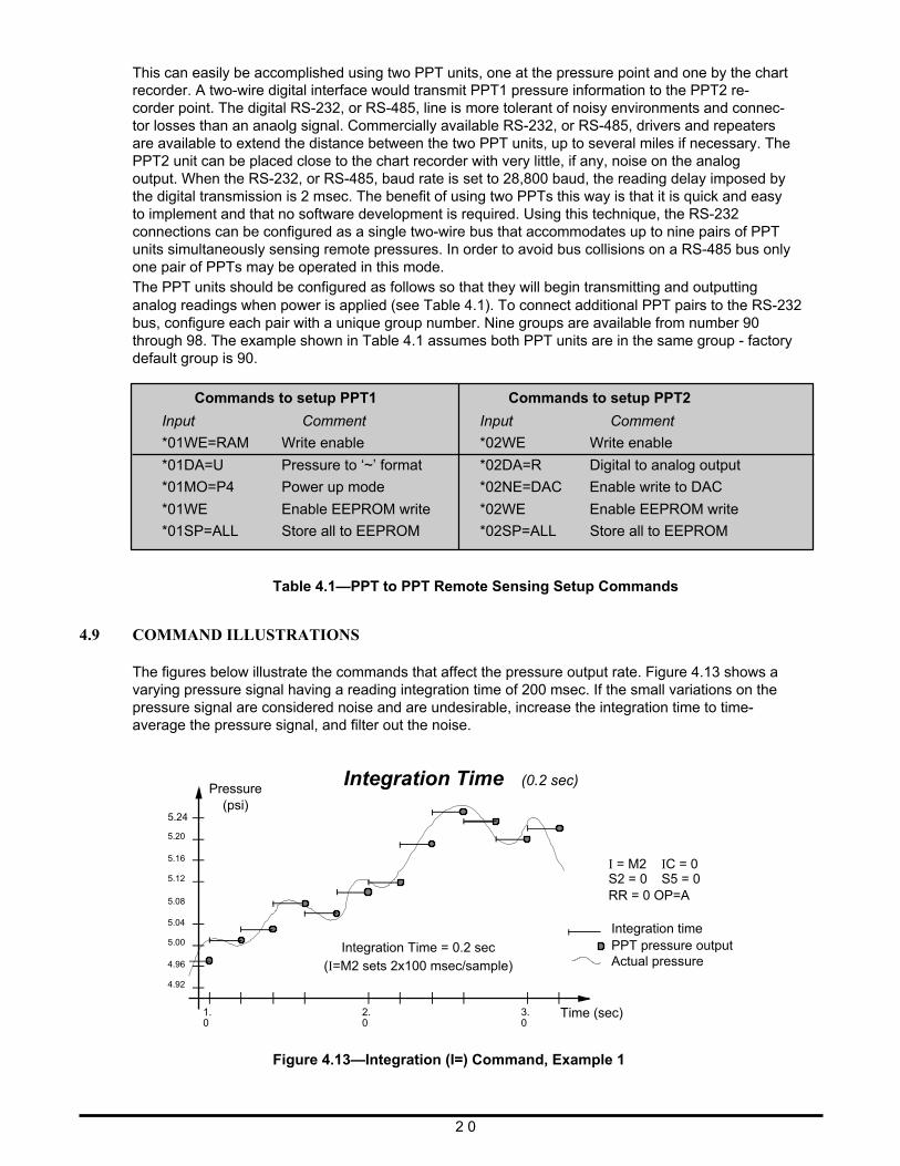
4.9 COMMAND ILLUSTRATIONS The figures below illustrate the commands that affect the pressure output rate. Figure 4.13 shows a varying pressure signal having a reading integration time of 200 msec. If the small variations on the pressure signal are considered noise and are undesirable, increase the integration time to time- average the pressure signal, and filter out the noise.
5.24
5.20
5.16
5.12
5.08
5.04
5.00
4.96
4.92
Pressure
(psi)
Integration Time (0.2 sec)
Integration Time = 0.2 sec (I=M2 sets 2x100 msec/sample)
I = M2 IC = 0 S2 = 0 S5 = 0 RR = 0 OP=A Integration time PPT pressure output Actual pressure
1. 0
2. 3. 0 0
Time (sec)
Figure 4.13—Integration (I=) Command, Example 1 2 0
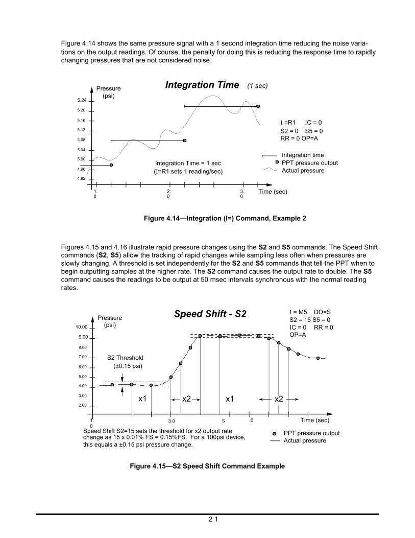
Figure 4.14 shows the same pressure signal with a 1 second integration time reducing the noise varia- tions on the output readings. Of course, the penalty for doing this is reducing the response time to rapidly changing pressures that are not considered noise.
5.24
5.20
5.16
5.12
5.08
5.04
5.00
4.96
4.92
Pressure
(psi)
Integration Time (1 sec)
Integration Time = 1 sec (I=R1 sets 1 reading/sec)
I =R1 IC = 0
S2 = 0 S5 = 0 RR = 0 OP=A
Integration time PPT pressure output Actual pressure
1. 0
2. 3. 0 0
Time (sec)
Figure 4.14—Integration (I=) Command, Example 2 Figures 4.15 and 4.16 illustrate rapid pressure changes using the S2 and S5 commands. The Speed Shift commands (S2, S5) allow the tracking of rapid changes while sampling less often when pressures are slowly changing. A threshold is set independently for the S2 and S5 commands that tell the PPT when to begin outputting samples at the higher rate. The S2 command causes the output rate to double. The S5 command causes the readings to be output at 50 msec intervals synchronous with the normal reading rates.
10.00
9.00
8.00
7.00
6.00
5.00
4.00
3.00
2.00
1. 0
Pressure
(psi)
S2 Threshold (±0.15 psi)
x1
Speed Shift - S2
x2 x1 3.0 5
.0
x2
I = M5 DO=S S2 = 15 S5 = 0 IC = 0 RR = 0 OP=A
Time (sec)
Speed Shift S2=15 sets the threshold for x2 output rate change as 15 x 0.01% FS = 0.15%FS. For a 100psi device, this equals a ±0.15 psi pressure change.
PPT pressure output Actual pressure
Figure 4.15—S2 Speed Shift Command Example
2 1
10.00
9.00
8.00
7.00
6.00
5.00
4.00
3.00
2.00
Pressure (psi) S5 Threshold
(±0.20 psi)
Speed Shift - S5 50 msec readings
I = M5 DO=S S2 = 0 S5 = 20 IC = 0 RR = 0 OP=A
50 msec readings
1. 0
3.0
5
.0
Time (sec)
Speed Shift (S5=20) sets the threshold for 50 msec output rate change as 20 x 0.01% FS = 0.20%FS. For a 100psi device, this equals a ±0.20 psi pressure change.
PPT pressure output Actual pressure
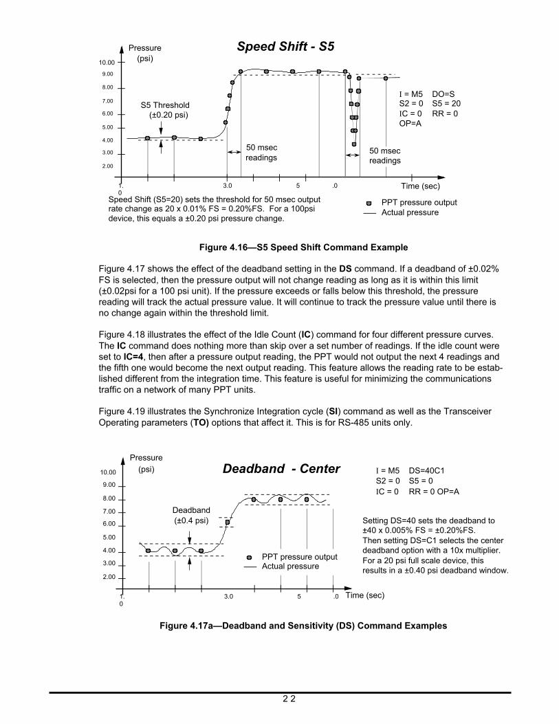
Figure 4.16—S5 Speed Shift Command Example
Figure 4.17 shows the effect of the deadband setting in the DS command. If a deadband of ±0.02% FS is selected, then the pressure output will not change reading as long as it is within this limit (±0.02psi for a 100 psi unit). If the pressure exceeds or falls below this threshold, the pressure reading will track the actual pressure value. It will continue to track the pressure value until there is no change again within the threshold limit.
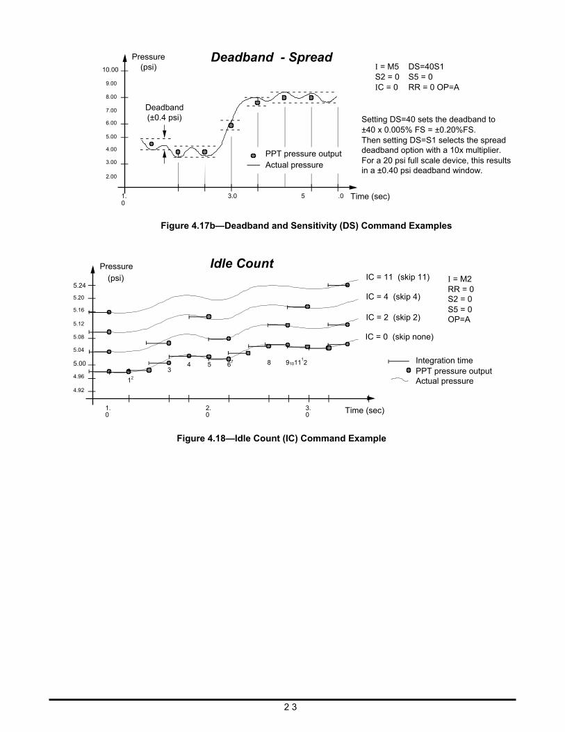
Figure 4.18 illustrates the effect of the Idle Count (IC) command for four different pressure curves. The IC command does nothing more than skip over a set number of readings. If the idle count were set to IC=4, then after a pressure output reading, the PPT would not output the next 4 readings and the fifth one would become the next output reading. This feature allows the reading rate to be estab- lished different from the integration time. This feature is useful for minimizing the communications traffic on a network of many PPT units.
Figure 4.19 illustrates the Synchronize Integration cycle (SI) command as well as the Transceiver Operating parameters (TO) options that affect it. This is for RS-485 units only.
Pressure
10.00
9.00
8.00
7.00
6.00
5.00
4.00
3.00
2.00
1. 0
(psi)
Deadband (±0.4 psi)
Deadband - Center PPT pressure output Actual pressure
3.0 5 .0
I = M5 DS=40C1 S2 = 0 S5 = 0 IC = 0 RR = 0 OP=A
Setting DS=40 sets the deadband to ±40 x 0.005% FS = ±0.20%FS. Then setting DS=C1 selects the center deadband option with a 10x multiplier. For a 20 psi full scale device, this results in a ±0.40 psi deadband window.
Time (sec)
Figure 4.17a—Deadband and Sensitivity (DS) Command Examples
2 2
10.00
9.00
8.00
7.00
6.00
5.00
4.00
3.00
2.00
Pressure
(psi) Deadband (±0.4 psi)
Deadband - Spread
PPT pressure output Actual pressure
I = M5 DS=40S1 S2 = 0 S5 = 0 IC = 0 RR = 0 OP=A
Setting DS=40 sets the deadband to ±40 x 0.005% FS = ±0.20%FS. Then setting DS=S1 selects the spread deadband option with a 10x multiplier. For a 20 psi full scale device, this results in a ±0.40 psi deadband window.
1. 0
3.0
5
.0
Time (sec)
Pressure
Figure 4.17b—Deadband and Sensitivity (DS) Command Examples
Idle Count 5.24
5.20
5.16
5.12
5.08
5.04
(psi) IC = 11 (skip 11) IC = 4 (skip 4) IC = 2 (skip 2) IC = 0 (skip none)
I = M2 RR = 0 S2 = 0 S5 = 0 OP=A
5.00
4.96
4.92
12
3
4 5 67 8 91011
12 Integration time
PPT pressure output Actual pressure
1. 0
2. 0
3. 0
Time (sec)
Figure 4.18—Idle Count (IC) Command Example 2 3
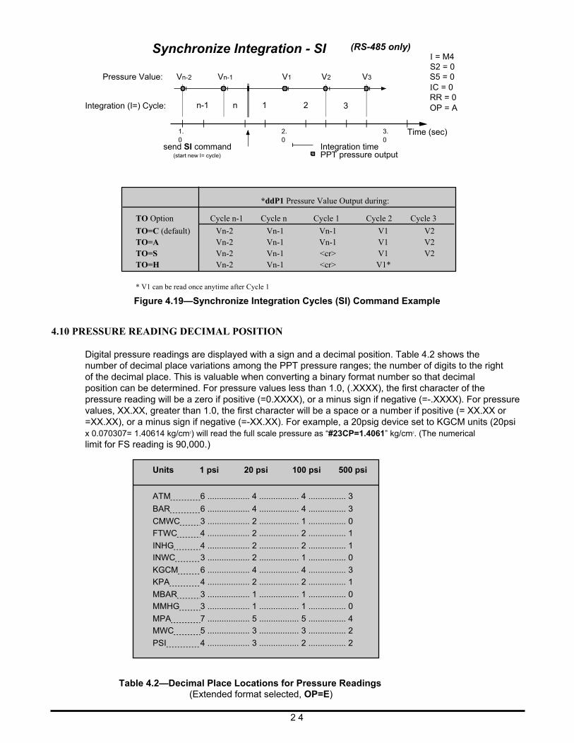
Synchronize Integration - SI (RS-485 only)
I = M4 S2 = 0
Pressure Value: Integration (I=) Cycle:
Vn-2
1. 0
n-1
Vn-1
n
1
V1
2. 0
2
V2 3
V3
3. 0
S5 = 0 IC = 0 RR = 0 OP = A
Time (sec)
send SI command (start new I= cycle)
Integration time PPT pressure output
*ddP1 Pressure Value Output during:
TO Option Cycle n-1 Cycle n Cycle 1 Cycle 2 Cycle 3
TO=C (default) TO=A TO=S TO=H
Vn-2 Vn-2 Vn-2 Vn-2
Vn-1 Vn-1 Vn-1 Vn-1
Vn-1 Vn-1 <cr> <cr>
V1 V1 V1 V1*
V2 V2 V2
* V1 can be read once anytime after Cycle 1
Figure 4.19—Synchronize Integration Cycles (SI) Command Example
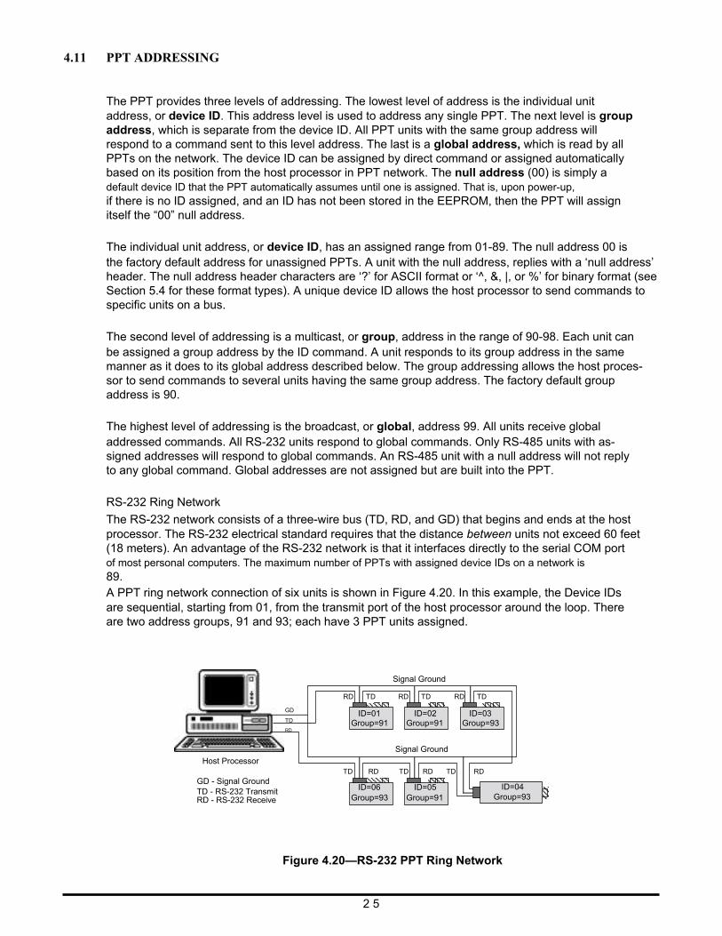
4.10 PRESSURE READING DECIMAL POSITION Digital pressure readings are displayed with a sign and a decimal position. Table 4.2 shows the number of decimal place variations among the PPT pressure ranges; the number of digits to the right of the decimal place. This is valuable when converting a binary format number so that decimal position can be determined. For pressure values less than 1.0, (.XXXX), the first character of the pressure reading will be a zero if positive (=0.XXXX), or a minus sign if negative (=-.XXXX). For pressure values, XX.XX, greater than 1.0, the first character will be a space or a number if positive (= XX.XX or =XX.XX), or a minus sign if negative (=-XX.XX). For example, a 20psig device set to KGCM units (20psi x 0.070307= 1.40614 kg/cm2) will read the full scale pressure as “#23CP=1.4061” kg/cm2. (The numerical limit for FS reading is 90,000.)
Units
1 psi
20 psi
100 psi 500 psi
ATM 6 .................. 4 ................. 4 ................ 3
BAR 6 .................. 4 ................. 4 ................ 3
CMWC 3 .................. 2 ................. 1 ................ 0
FTWC 4 .................. 2 ................. 2 ................ 1
INHG 4 .................. 2 ................. 2 ................ 1
INWC 3 .................. 2 ................. 1 ................ 0
KGCM 6 .................. 4 ................. 4 ................ 3
KPA 4 .................. 2 ................. 2 ................ 1
MBAR 3 .................. 1 ................. 1 ................ 0
MMHG 3 .................. 1 ................. 1 ................ 0
MPA 7 .................. 5 ................. 5 ................ 4
MWC 5 .................. 3 ................. 3 ................ 2
PSI 4 .................. 3 ................. 2 ................ 2 Table 4.2—Decimal Place Locations for Pressure Readings (Extended format selected, OP=E)
2 4
4.11 PPT ADDRESSING
The PPT provides three levels of addressing. The lowest level of address is the individual unit address, or device ID. This address level is used to address any single PPT. The next level is group address, which is separate from the device ID. All PPT units with the same group address will respond to a command sent to this level address. The last is a global address, which is read by all PPTs on the network. The device ID can be assigned by direct command or assigned automatically based on its position from the host processor in PPT network. The null address (00) is simply a default device ID that the PPT automatically assumes until one is assigned. That is, upon power-up, if there is no ID assigned, and an ID has not been stored in the EEPROM, then the PPT will assign itself the “00” null address.
The individual unit address, or device ID, has an assigned range from 01-89. The null address 00 is the factory default address for unassigned PPTs. A unit with the null address, replies with a ‘null address’ header. The null address header characters are ‘?’ for ASCII format or ‘^, &, |, or %’ for binary format (see Section 5.4 for these format types). A unique device ID allows the host processor to send commands to specific units on a bus.
The second level of addressing is a multicast, or group, address in the range of 90-98. Each unit can be assigned a group address by the ID command. A unit responds to its group address in the same manner as it does to its global address described below. The group addressing allows the host proces- sor to send commands to several units having the same group address. The factory default group address is 90.
The highest level of addressing is the broadcast, or global, address 99. All units receive global addressed commands. All RS-232 units respond to global commands. Only RS-485 units with as- signed addresses will respond to global commands. An RS-485 unit with a null address will not reply to any global command. Global addresses are not assigned but are built into the PPT.
RS-232 Ring Network
The RS-232 network consists of a three-wire bus (TD, RD, and GD) that begins and ends at the host processor. The RS-232 electrical standard requires that the distance between units not exceed 60 feet (18 meters). An advantage of the RS-232 network is that it interfaces directly to the serial COM port of most personal computers. The maximum number of PPTs with assigned device IDs on a network is 89. A PPT ring network connection of six units is shown in Figure 4.20. In this example, the Device IDs are sequential, starting from 01, from the transmit port of the host processor around the loop. There are two address groups, 91 and 93; each have 3 PPT units assigned.
Signal Ground
Host Processor
GD
TD
RD
RD TD
ID=01 Group=91
RD TD
ID=02 Group=91
Signal Ground
RD TD
ID=03 Group=93
GD - Signal Ground TD - RS-232 Transmit RD - RS-232 Receive
TD RD
ID=06 Group=93
TD RD
ID=05 Group=91
TD RD ID=04
Group=93
Figure 4.20—RS-232 PPT Ring Network
2 5
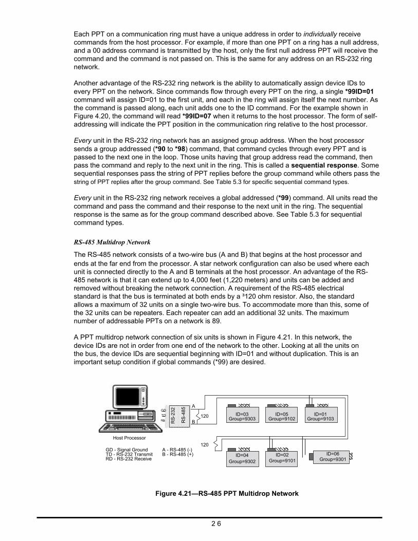
Each PPT on a communication ring must have a unique address in order to individually receive commands from the host processor. For example, if more than one PPT on a ring has a null address, and a 00 address command is transmitted by the host, only the first null address PPT will receive the command and the command is not passed on. This is the same for any address on an RS-232 ring network.
Another advantage of the RS-232 ring network is the ability to automatically assign device IDs to every PPT on the network. Since commands flow through every PPT on the ring, a single *99ID=01 command will assign ID=01 to the first unit, and each in the ring will assign itself the next number. As the command is passed along, each unit adds one to the ID command. For the example shown in Figure 4.20, the command will read *99ID=07 when it returns to the host processor. The form of self- addressing will indicate the PPT position in the communication ring relative to the host processor.
Every unit in the RS-232 ring network has an assigned group address. When the host processor sends a group addressed (*90 to *98) command, that command cycles through every PPT and is passed to the next one in the loop. Those units having that group address read the command, then pass the command and reply to the next unit in the ring. This is called a sequential response. Some sequential responses pass the string of PPT replies before the group command while others pass the string of PPT replies after the group command. See Table 5.3 for specific sequential command types.
Every unit in the RS-232 ring network receives a global addressed (*99) command. All units read the command and pass the command and their response to the next unit in the ring. The sequential response is the same as for the group command described above. See Table 5.3 for sequential command types.
RS-485 Multidrop Network
The RS-485 network consists of a two-wire bus (A and B) that begins at the host processor and ends at the far end from the processor. A star network configuration can also be used where each unit is connected directly to the A and B terminals at the host processor. An advantage of the RS- 485 network is that it can extend up to 4,000 feet (1,220 meters) and units can be added and removed without breaking the network connection. A requirement of the RS-485 electrical standard is that the bus is terminated at both ends by a ³120 ohm resistor. Also, the standard allows a maximum of 32 units on a single two-wire bus. To accommodate more than this, some of the 32 units can be repeaters. Each repeater can add an additional 32 units. The maximum number of addressable PPTs on a network is 89.
A PPT multidrop network connection of six units is shown in Figure 4.21. In this network, the device IDs are not in order from one end of the network to the other. Looking at all the units on the bus, the device IDs are sequential beginning with ID=01 and without duplication. This is an important setup condition if global commands (*99) are desired.
A
GD
Host Processor
TD RD
B
120
120
ID=03 Group=9303
ID=05 Group=9102
ID=01 Group=9103
GD - Signal Ground TD - RS-232 Transmit RD - RS-232 Receive
A - RS-485 (-) B - RS-485 (+) ID=04
Group=9302 ID=02
Group=9101
ID=06 Group=9301
Figure 4.21—RS-485 PPT Multidrop Network 2 6
RS
-232
RS
-485
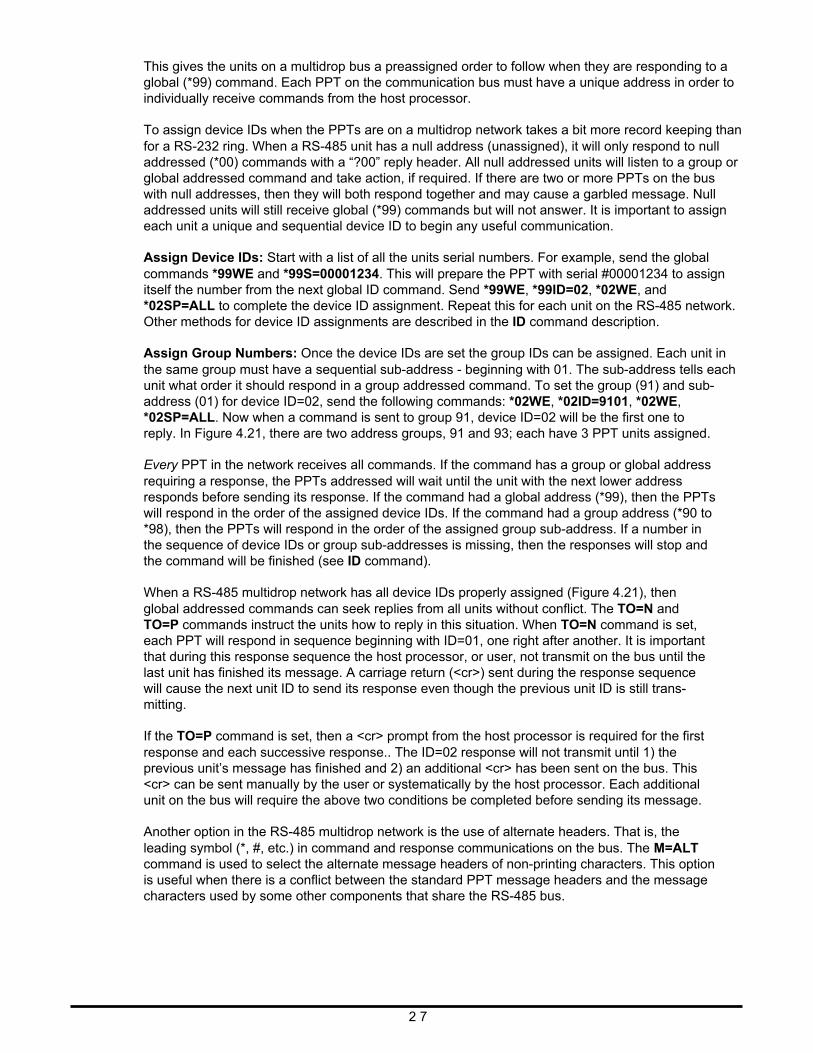
This gives the units on a multidrop bus a preassigned order to follow when they are responding to a global (*99) command. Each PPT on the communication bus must have a unique address in order to individually receive commands from the host processor.
To assign device IDs when the PPTs are on a multidrop network takes a bit more record keeping than for a RS-232 ring. When a RS-485 unit has a null address (unassigned), it will only respond to null addressed (*00) commands with a “?00” reply header. All null addressed units will listen to a group or global addressed command and take action, if required. If there are two or more PPTs on the bus with null addresses, then they will both respond together and may cause a garbled message. Null addressed units will still receive global (*99) commands but will not answer. It is important to assign each unit a unique and sequential device ID to begin any useful communication.
Assign Device IDs: Start with a list of all the units serial numbers. For example, send the global commands *99WE and *99S=00001234. This will prepare the PPT with serial #00001234 to assign itself the number from the next global ID command. Send *99WE, *99ID=02, *02WE, and *02SP=ALL to complete the device ID assignment. Repeat this for each unit on the RS-485 network. Other methods for device ID assignments are described in the ID command description.
Assign Group Numbers: Once the device IDs are set the group IDs can be assigned. Each unit in the same group must have a sequential sub-address - beginning with 01. The sub-address tells each unit what order it should respond in a group addressed command. To set the group (91) and sub- address (01) for device ID=02, send the following commands: *02WE, *02ID=9101, *02WE, *02SP=ALL. Now when a command is sent to group 91, device ID=02 will be the first one to reply. In Figure 4.21, there are two address groups, 91 and 93; each have 3 PPT units assigned.
Every PPT in the network receives all commands. If the command has a group or global address requiring a response, the PPTs addressed will wait until the unit with the next lower address responds before sending its response. If the command had a global address (*99), then the PPTs will respond in the order of the assigned device IDs. If the command had a group address (*90 to *98), then the PPTs will respond in the order of the assigned group sub-address. If a number in the sequence of device IDs or group sub-addresses is missing, then the responses will stop and the command will be finished (see ID command).
When a RS-485 multidrop network has all device IDs properly assigned (Figure 4.21), then global addressed commands can seek replies from all units without conflict. The TO=N and TO=P commands instruct the units how to reply in this situation. When TO=N command is set, each PPT will respond in sequence beginning with ID=01, one right after another. It is important that during this response sequence the host processor, or user, not transmit on the bus until the last unit has finished its message. A carriage return (<cr>) sent during the response sequence will cause the next unit ID to send its response even though the previous unit ID is still trans- mitting.
If the TO=P command is set, then a <cr> prompt from the host processor is required for the first response and each successive response.. The ID=02 response will not transmit until 1) the previous unit’s message has finished and 2) an additional <cr> has been sent on the bus. This <cr> can be sent manually by the user or systematically by the host processor. Each additional unit on the bus will require the above two conditions be completed before sending its message.
Another option in the RS-485 multidrop network is the use of alternate headers. That is, the leading symbol (*, #, etc.) in command and response communications on the bus. The M=ALT command is used to select the alternate message headers of non-printing characters. This option is useful when there is a conflict between the standard PPT message headers and the message characters used by some other components that share the RS-485 bus.
2 7
5
5.1
COMMANDS
COMMAND FORMAT
Communication between the host or control processor and a PPT is accomplished by message trans- fers, or commands and replies. Communications initiated by the host processor to one or more PPTs are called commands and must begin with an ‘*’ or a ‘~’ header character. All commands must be terminated by a <cr> (carriage return or ENTER key). Communications initiated by a PPT to the host are called responses or replies, and begin with one of ten unique header characters (2 for ASCII, 8 for binary).
Commands may either request information from one or more PPTs such as read pressure, or direct action to one or more PPTs such as change a configuration value or operating mode.
Typical PPT command format: *ddcc = nnn <cr>
Where: * is the command header character (a ‘~’ in one case) dd is the decimal address of the command message (00-99) cc is the command code. The command code characters can be one letter, two letters, or
a letter and a number. The letters are not case sensitive; i.e., either an upper case or lower case may be used. The PPT will convert the character to upper case.
= equal sign (required in some commands) nnn additional characters (required in some commands) <cr> carriage return (do not type, press the ENTER key)
Note: For RS-485 mode, alternate headers are available. (see MO command)
For RS-232 mode, when manually applying commands to one or more PPTs which are in the continu- ous send mode (P2, P4, T2, T4), the special header character ‘$’ should be used to suspend all PPT transmissions while the command message is being typed. The ‘$’ is immediately followed by the normal command format.
Also for RS-232 mode, if an erroneous command is sent to the PPT, it is echoed back to the host in the same form it was sent. The only exception to this is when a group or global address command (ID = 90 to 99) is sent such as *99S2=15<cr>. These addresses will always echo the command back to the host processor after being read by all PPTs.
Commands are not executed until the carriage return is applied; therefore, any command message may be re-entered at any time prior to the carriage return. To do this, type a ‘*’ followed by the command, or press a carriage return and retype the command.
Only the minimum number of characters is required for command inputs to distinguish between various command options. For example, DU=MB, DU=MBAR, or DU=MBXYZ will all set the display units to millibar, since only the first two characters (MB) are needed. Also, when a parameter value is entered that exceeds the stated range for that value, the parameter will be set to the maxi- mum value for that range.
A special binary format command that controls the DAC analog output, uses a ‘~’ (tilde) header character instead of an ‘*’ (asterisk). This command is sent in binary form, as opposed to ASCII, and is a more efficient alternate to the standard command requiring less data to be transmitted (see Section 5.4 for binary and ASCII descriptions). For this command, the ‘~’ has the same header functional characteristics as the ‘*’ described above.
2 8
5.2
5.3
5.4
INFORMATION REQUEST COMMANDS
Information request commands retrieve information from the PPT as an inquiry. One example would be a speed shift command inquiry. The command *00S2 would request the x2 speed shift threshold value. The response may be ?01S2=12, assuming the unit had not been assigned a device ID. A characteristic of the information request command is that the ‘=nnn’ portion of the command format is dropped.
Most commands that set parameters may be used in this form to inquire about that parameter’s value. For commands that have a single letter command code (cc), use that letter followed by an ‘=’ equal sign to form an inquiry. For instance, to set the tare control use *00T=SET. To inquire about the tare control, use *00T= as an information request.
ACTION DIRECTING COMMANDS
Action directing commands can 1) change the PPT configuration, 2) set specific parameter values, 3) activate or deactivate controls, or 4) store information in EEPROM.
Examples of action directing commands are:
1) *00MO=P2M2 Continuous pressure readings and user message at power-up 2) *00IC=9 Set the idle count value to 9 3) *00TC=ON Turn on the tare control switch 4) *00B=02-12-95 Set B string in EEPROM to “02-12-95”
A characteristic of most action directing commands is that they are preceded by a RAM, or EEPROM, write enable (WE) command or an analog control enable (NE) command. This signals the PPT to write the action directing parameter(s) and is provided as a safeguard to prevent inadvertent changes. The only exception to this is the initialization (IN) command which is activated upon receipt.
COMMAND REPLIES - GENERAL
Replies are transmitted from the PPT in response to an information request inquiry or due to a power applied condition. All replies end with a <cr> carriage return character, which can be used as a delimiter, to distinguish between sequential responses. Replies have two forms: the ASCII format – which consists of standard keyboard alphanumeric characters (see Section 5.5), and the binary format – which require fewer data bytes that are encoded for computer translation (see Section 5.6).
The binary format replies are for pressure readings using the P3 and P4 commands. The replies are more compact, require less data transmission, and more than double the RS-232, or RS-485, data transfer capacity. However, the binary format is difficult for people to translate and is best left for a computer to interpret.
The ASCII format characters have readable output values and do not require user interpretation. However, the binary format will transmit a pressure reading in 6 bytes where it may take up to 16 bytes in the ASCII format. (See the Binary Format Replies description below for a detailed explana- tion of the address and pressure encoding.) There is a mode (OP=R) that can transmit ASCII format in 8 bytes.
When an information request command is sent to a PPT or group of PPTs the reply will take on different forms based on the state of the PPT, the address of the PPT, or the out-of-range condition for that parameter.
2 9
5.5
A pressure-over-range error condition will occur when the applied pressure is greater than or equal to 1% of full scale (FS) above the FS limit. For example, if the pressure applied to a 20 psi unit is •20.200 psi, then an over range error condition is set (see RS command). Similarly, an under range condition occurs when the applied pressure is greater than or equal to 1%FS below the minimum limit. To indicate an out-of-range condition (greater than ±1% FS), the equal ‘=’ sign will be replaced by an exclamation point ‘!’ in the pressure reading reply. This indicator will disappear when the applied pressure is in range, but the RS command error flag will continue to be set until it is cleared by an inquiry.
The maximum reading will flatten out between 1% and 5% beyond the FS limit with increasing pressure. This limit varies from device to device but will continue to display the out-of-range indica- tor (“!” in place of “=“) until the pressure drops below 1% over FS limit.
ASCII FORMAT REPLIES
Most commands use the ASCII format reply and may be identified by the header character (ASCII – American Standard for Coded Information Interchange). The ASCII format consists of standard keyboard alpha-numeric characters and symbols. The header character is the first character in the reply from the PPT. The ASCII format information request reply uses the following header charac- ters:
# ASCII format reply from an assigned address PPT. ? ASCII format reply from a null address PPT.
Example replies to command code (cc) are: (where xx = the parameter value)
#ddcc=xx reply from unit with an assigned address (dd). #ddcc!xx reply from unit with an assigned address (dd) when 1) pressure or temperature
reading is out-of-range (over/under limit = ±1%FS) or, 2) an EEPROM parity error has occurred (pressure reading will output zero).
#ddcc=.. reply from unit with an assigned address (dd) when data is not available yet from the PPT or the output was disabled (see DA command). Request again.
?ddcc=xx reply from a null address unit (dd). ?ddcc!xx reply from a null address unit (dd) when 1) pressure or temperature reading is out-of-
range (over/under limit = ±1%FS) or, 2) an EEPROM parity error has occurred (pressure reading will output zero).
?ddcc=.. reply from a null address unit (dd) when data is not available yet from the PPT or the output was disabled (see DA command). Request again.
Note: For multidrop bus mode alternate header descriptions see MO command description.
3 0
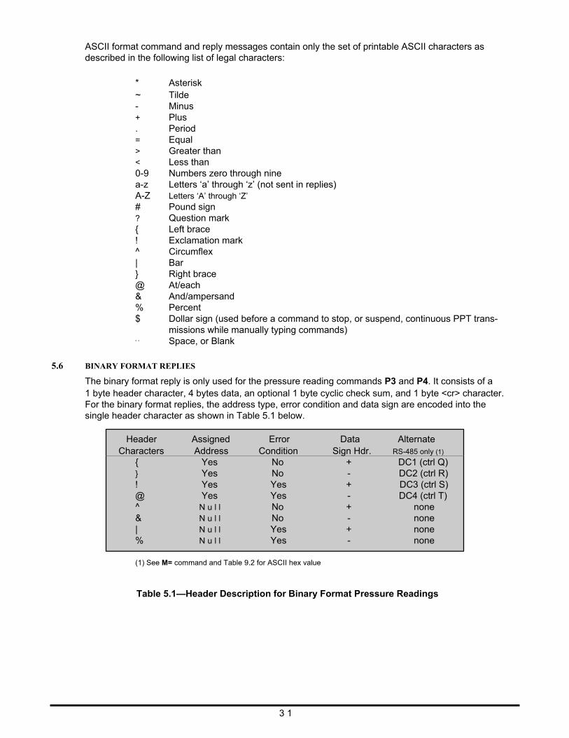
ASCII format command and reply messages contain only the set of printable ASCII characters as described in the following list of legal characters:
* ~ - + . = > < 0-9 a-z
Asterisk Tilde Minus Plus Period Equal Greater than Less than Numbers zero through nine Letters ‘a’ through ‘z’ (not sent in replies)
A-Z Letters ‘A’ through ‘Z’ # ? { ! ^ | } @ & % $
‘ ‘
Pound sign Question mark Left brace Exclamation mark Circumflex Bar Right brace At/each And/ampersand Percent Dollar sign (used before a command to stop, or suspend, continuous PPT trans- missions while manually typing commands) Space, or Blank
5.6
BINARY FORMAT REPLIES
The binary format reply is only used for the pressure reading commands P3 and P4. It consists of a 1 byte header character, 4 bytes data, an optional 1 byte cyclic check sum, and 1 byte <cr> character. For the binary format replies, the address type, error condition and data sign are encoded into the single header character as shown in Table 5.1 below.
Header
Assigned
Error
Data
Alternate Characters Address Condition Sign Hdr. RS-485 only (1)
{ } ! @ ^ & | %
Yes Yes Yes Yes
N u l l N u l l N u l l N u l l
No No Yes Yes No No Yes Yes
+ - + - + - + -
DC1 (ctrl Q) DC2 (ctrl R) DC3 (ctrl S) DC4 (ctrl T)
none none none none
(1) See M= command and Table 9.2 for ASCII hex value Table 5.1—Header Description for Binary Format Pressure Readings
3 1
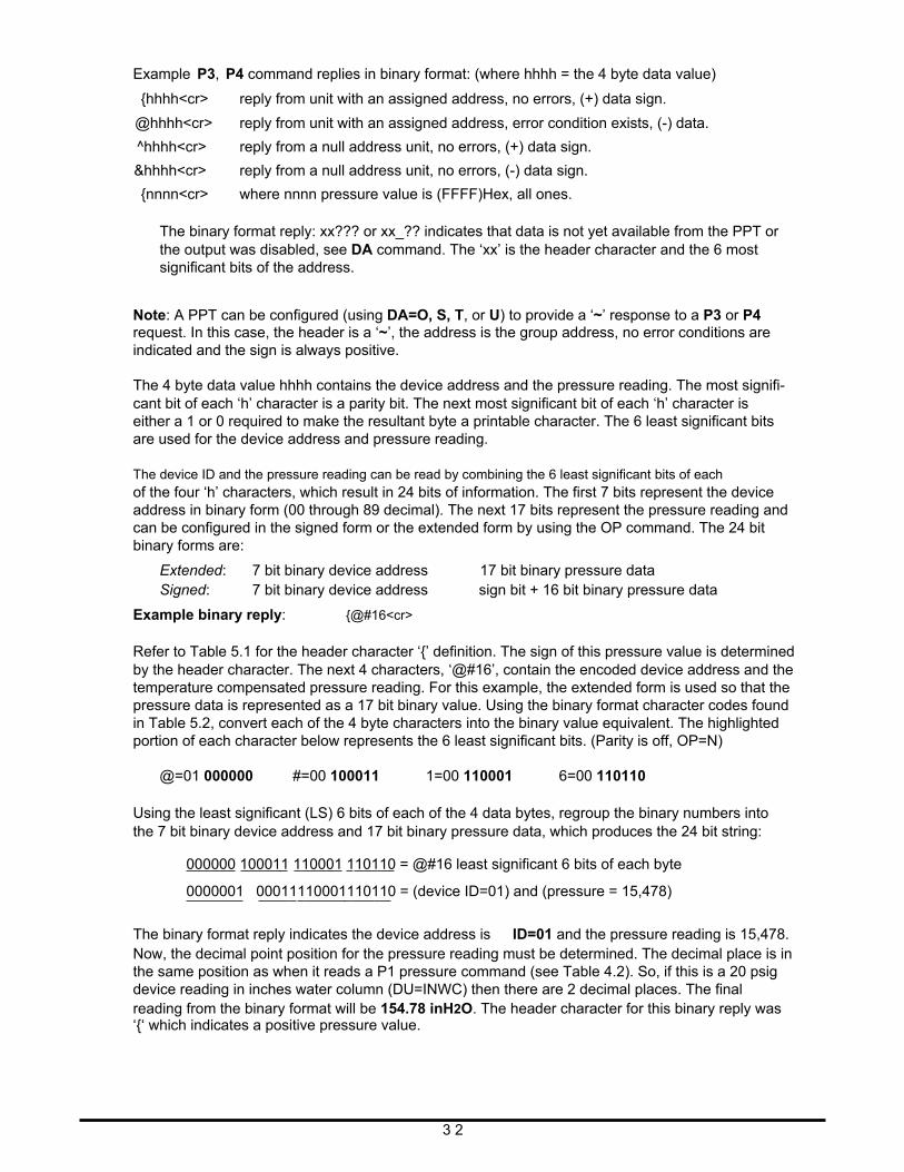
Example P3, P4 command replies in binary format: (where hhhh = the 4 byte data value)
{hhhh<cr> reply from unit with an assigned address, no errors, (+) data sign.
@hhhh<cr> reply from unit with an assigned address, error condition exists, (-) data.
^hhhh<cr> reply from a null address unit, no errors, (+) data sign.
&hhhh<cr> reply from a null address unit, no errors, (-) data sign.
{nnnn<cr> where nnnn pressure value is (FFFF)Hex, all ones.
The binary format reply: xx??? or xx_?? indicates that data is not yet available from the PPT or the output was disabled, see DA command. The ‘xx’ is the header character and the 6 most significant bits of the address.
Note: A PPT can be configured (using DA=O, S, T, or U) to provide a ‘~’ response to a P3 or P4 request. In this case, the header is a ‘~’, the address is the group address, no error conditions are indicated and the sign is always positive.
The 4 byte data value hhhh contains the device address and the pressure reading. The most signifi- cant bit of each ‘h’ character is a parity bit. The next most significant bit of each ‘h’ character is either a 1 or 0 required to make the resultant byte a printable character. The 6 least significant bits are used for the device address and pressure reading.
The device ID and the pressure reading can be read by combining the 6 least significant bits of each of the four ‘h’ characters, which result in 24 bits of information. The first 7 bits represent the device address in binary form (00 through 89 decimal). The next 17 bits represent the pressure reading and can be configured in the signed form or the extended form by using the OP command. The 24 bit binary forms are:
Extended: 7 bit binary device address 17 bit binary pressure data Signed: 7 bit binary device address sign bit + 16 bit binary pressure data
Example binary reply: {@#16<cr>
Refer to Table 5.1 for the header character ‘{’ definition. The sign of this pressure value is determined by the header character. The next 4 characters, ‘@#16’, contain the encoded device address and the temperature compensated pressure reading. For this example, the extended form is used so that the pressure data is represented as a 17 bit binary value. Using the binary format character codes found in Table 5.2, convert each of the 4 byte characters into the binary value equivalent. The highlighted portion of each character below represents the 6 least significant bits. (Parity is off, OP=N)
@=01 000000
#=00 100011
1=00 110001
6=00 110110
Using the least significant (LS) 6 bits of each of the 4 data bytes, regroup the binary numbers into the 7 bit binary device address and 17 bit binary pressure data, which produces the 24 bit string:
000000 100011 110001 110110 = @#16 least significant 6 bits of each byte
0000001 00011110001110110 = (device ID=01) and (pressure = 15,478)
The binary format reply indicates the device address is ID=01 and the pressure reading is 15,478. Now, the decimal point position for the pressure reading must be determined. The decimal place is in the same position as when it reads a P1 pressure command (see Table 4.2). So, if this is a 20 psig device reading in inches water column (DU=INWC) then there are 2 decimal places. The final reading from the binary format will be 154.78 inH2O. The header character for this binary reply was ‘{‘ which indicates a positive pressure value.
3 2
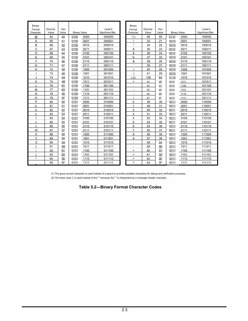
Binary
Format Character
Decimal
Value
Hex
Value Binary Value
Least 6
Significant Bits
Binary
Format Character
Decimal Value
Hex
Value Binary Value
Least 6
Significant Bits
@
A
B
C
D
E
F
G
H
I
64 40 0100 0000
65 41 0100 0001
66 42 0100 0010
67 43 0100 0011
68 44 0100 0100
69 45 0100 0101
70 46 0100 0110
71 47 0100 0111
72 48 0100 1000
73 49 0100 1001
000000
000001
000010
000011
000100
000101
000110
000111
001000
001001
‘ (1)
!
"
#
$
%
&
’
(
)
96
33
34
35
36
37
38
39
40
41
60 0110 0000
21 0010 0001
22 0010 0010
23 0010 0011
24 0010 0100
25 0010 0101
26 0010 0110
27 0010 0111
28 0010 1000
29 0010 1001
100000
100001
100010
100011
100100
100101
100110
100111
101000
101001
J
K
L
M
N
O
74 4A 0100 1010
75 4B 0100 1011
76 4C 0100 1100
77 4D 0100 1101
78 4E 0100 1110
79 4F 0100 1111
001010
001011
001100
001101
001110
001111
j (2)
+
,
-
.
/
106 6A 0110 1010
43 2B 0010 1011
44 2C 0010 1100
45 2D 0010 1101
46 2E 0010 1110
47 2F 0010 1111
101010
101011
101100
101101
101110
101111
P
Q
R
S
T
U
V
W
X
Y
80 50 0101 0000
81 51 0101 0001
82 52 0101 0010
83 53 0101 0011
84 54 0101 0100
85 55 0101 0101
86 56 0101 0110
87 57 0101 0111
88 58 0101 1000
89 59 0101 1001
010000
010001
010010
010011
010100
010101
010110
010111
011000
011001
0
1
2
3
4
5
6
7
8
9
48
49
50
51
52
53
54
55
56
57
30 0011 0000
31 0011 0001
32 0011 0010
33 0011 0011
34 0011 0100
35 0011 0101
36 0011 0110
37 0011 0111
38 0011 1000
39 0011 1001
110000
110001
110010
110011
110100
110101
110110
110111
111000
111001
Z
[
\
]
^
_
90 5A 0101 1010
91 5B 0101 1011
92 5C 0101 1100
93 5D 0101 1101
94 5E 0101 1110
95 5F 0101 1111
011010
011011
011100
011101
011110
011111
:
:
<
=
>
?
58 3A 0011 1010
59 3B 0011 1011
60 3C 0011 1100
61 3D 0011 1101
62 3E 0011 1110
63 3F 0011 1111
111010
111011
111100
111101
111110
111111
(1) The grave accent character is used instead of a space to provide printable characters for debug and verification purposes.
(2) The lower case ‘j’ is used instead of the ‘*’ because the ‘*’ is interpreted as a message header character.
Table 5.2—Binary Format Character Codes
3 3
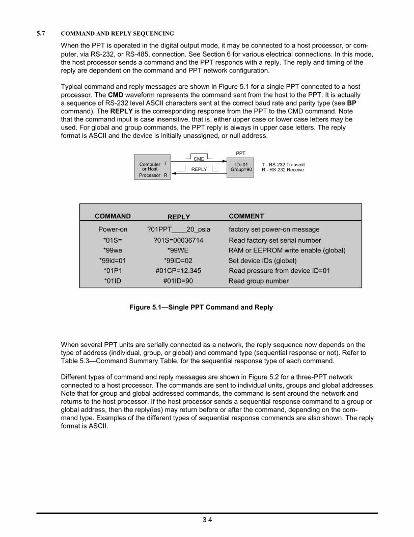
5.7 COMMAND AND REPLY SEQUENCING
When the PPT is operated in the digital output mode, it may be connected to a host processor, or com- puter, via RS-232, or RS-485, connection. See Section 6 for various electrical connections. In this mode, the host processor sends a command and the PPT responds with a reply. The reply and timing of the reply are dependent on the command and PPT network configuration.
Typical command and reply messages are shown in Figure 5.1 for a single PPT connected to a host processor. The CMD waveform represents the command sent from the host to the PPT. It is actually a sequence of RS-232 level ASCII characters sent at the correct baud rate and parity type (see BP command). The REPLY is the corresponding response from the PPT to the CMD command. Note that the command input is case insensitive, that is, either upper case or lower case letters may be used. For global and group commands, the PPT reply is always in upper case letters. The reply format is ASCII and the device is initially unassigned, or null address.
PPT CMD
Computer or Host
T REPLY
ID=01 Group=90
T - RS-232 Transmit R - RS-232 Receive
COMMAND
Power-on
*01S=
*99we
*99id=01
*01P1
*01ID
Processor R
REPLY
?01PPT____20_psia
?01S=00036714
*99WE
*99ID=02
#01CP=12.345
#01ID=90
COMMENT
factory set power-on message
Read factory set serial number
RAM or EEPROM write enable (global)
Set device IDs (global)
Read pressure from device ID=01
Read group number
Figure 5.1—Single PPT Command and Reply When several PPT units are serially connected as a network, the reply sequence now depends on the type of address (individual, group, or global) and command type (sequential response or not). Refer to Table 5.3—Command Summary Table, for the sequential response type of each command.
Different types of command and reply messages are shown in Figure 5.2 for a three-PPT network connected to a host processor. The commands are sent to individual units, groups and global addresses. Note that for group and global addressed commands, the command is sent around the network and returns to the host processor. If the host processor sends a sequential response command to a group or global address, then the reply(ies) may return before or after the command, depending on the com- mand type. Examples of the different types of sequential response commands are also shown. The reply format is ASCII.
3 4
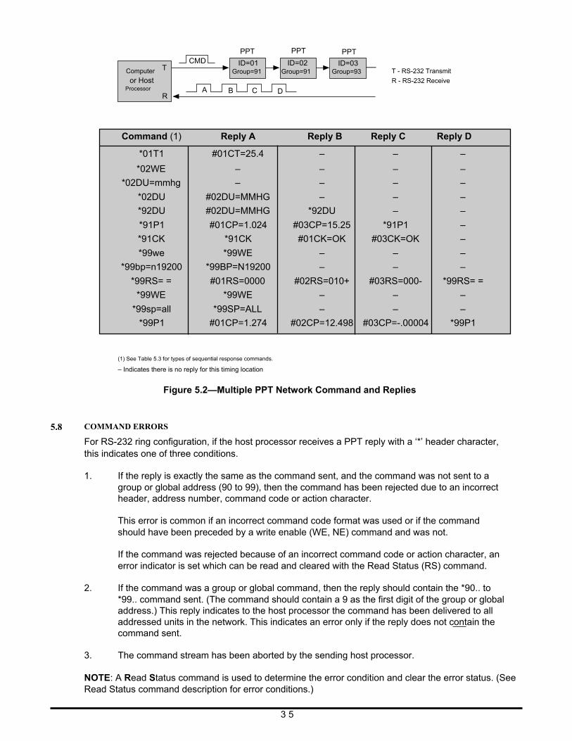
Computer
or Host Processor
T R
CMD
A
PPT
ID=01 Group=91
B C
PPT
ID=02 Group=91
D
PPT
ID=03 Group=93
T - RS-232 Transmit
R - RS-232 Receive
Command (1)
Reply A
Reply B Reply C Reply D
*01T1
*02WE
*02DU=mmhg
*02DU
*92DU
*91P1
*91CK
*99we
*99bp=n19200
*99RS= =
*99WE
*99sp=all
#01CT=25.4
–
–
#02DU=MMHG
#02DU=MMHG
#01CP=1.024
*91CK
*99WE
*99BP=N19200
#01RS=0000
*99WE
*99SP=ALL
–
–
–
–
*92DU
#03CP=15.25
#01CK=OK
–
–
#02RS=010+
–
–
–
–
–
–
–
*91P1
#03CK=OK
–
–
#03RS=000-
–
–
–
–
–
–
–
–
–
–
–
*99RS= =
–
–
*99P1 #01CP=1.274 #02CP=12.498 #03CP=-.00004 *99P1
5.8
(1) See Table 5.3 for types of sequential response commands.
– Indicates there is no reply for this timing location
Figure 5.2—Multiple PPT Network Command and Replies
COMMAND ERRORS
For RS-232 ring configuration, if the host processor receives a PPT reply with a ‘*’ header character, this indicates one of three conditions.
1. If the reply is exactly the same as the command sent, and the command was not sent to a group or global address (90 to 99), then the command has been rejected due to an incorrect header, address number, command code or action character.
This error is common if an incorrect command code format was used or if the command should have been preceded by a write enable (WE, NE) command and was not.
If the command was rejected because of an incorrect command code or action character, an error indicator is set which can be read and cleared with the Read Status (RS) command.
2. If the command was a group or global command, then the reply should contain the *90.. to *99.. command sent. (The command should contain a 9 as the first digit of the group or global address.) This reply indicates to the host processor the command has been delivered to all addressed units in the network. This indicates an error only if the reply does not contain the command sent.
3. The command stream has been aborted by the sending host processor.
NOTE: A Read Status command is used to determine the error condition and clear the error status. (See Read Status command description for error conditions.)
3 5
5.9
COMMAND SUMMARY TABLE
The PPT command set is summarized in Table 5.3—Command List. A more detailed description of each command can be found in Section 5.10—Command Descriptions.
Table heading explanations for Table 5.3—Command List:
Command Code: Two-character code (cc) in the command format. The command code characters can be one letter followed by an ‘=’ equal sign, two letters, a letter and a number, or a ‘~’ tilde. The letters are not case sensitive; i.e. either upper case or lower case may be used. The PPT will convert the characters to upper case.
Action Directing Command: Does this command change the PPT configuration? Yes—The command changes the PPT configuration as an action directing com- mand. No—The command is only an information request command.
Sequential Response with Group or Global Address: Commands that begin with a group or global address (ID=90-99), are passed through the PPT network from one device to the next and eventually end up back at the host proces- sor. The PPT response is sent with the command through the network. Before—The PPT response is sent before the group or global com- mand. This is a sequential response. After—The PPT response is sent after the group or global command. No—The PPT just passes the command through the network with no response.
Input or Output: Is information input to the PPT or output from the PPT? In—Com- mand is only used to input (action direct command) to the PPT. Out— Command is only used to output (request information inquiry) from the PPT. Both—Command can be used for either IN or OUT purposes.
Requires Write Enable: Is a WE command required before for this command? Yes—When sent as an action directed command, it must be preceded by a WE command. No—Never requires a WE command beforehand. These are request information commands only.
Terminates Continuous Commands: Will this command stop the PPT flow? Yes—This command will end the continuous flow of the P2, P4, T2, T4 com- mands. No—Command will not stop the continuous flow commands.
Write to EEPROM: Can this command have parameters stored in EEPROM? Yes— Parameter values associated with this command may be stored in EEPROM. No—Can not store anything from this command in EEPROM. All—Cause all parameters to be store in EEPROM.
Write to DAC: Can this command be written to the DAC? Yes—Command may be directed to the DAC. No—Command has nothing to do with the DAC
3 6
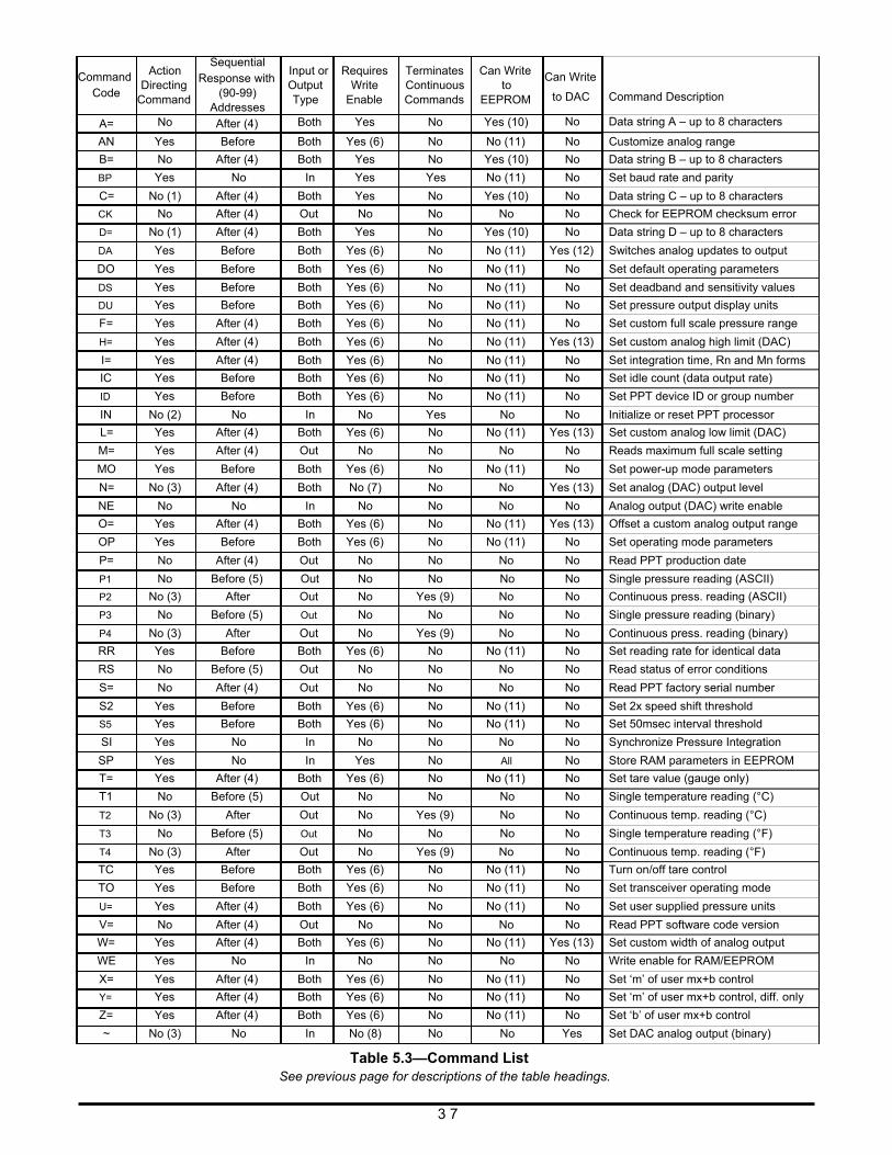
Command Code A=
Action
Directing Command
No
Sequential Response with
(90-99) Addresses After (4)
Input or Output Type
Both
Requires
Write Enable
Yes
Terminates Continuous Commands
No
Can Write
to EEPROM
Yes (10)
Can Write
to DAC Command Description
No Data string A – up to 8 characters
AN Yes Before Both Yes (6) No No (11) No Customize analog range
B=
BP
C=
CK
D=
No
Yes
No (1)
No
No (1)
After (4)
No
After (4)
After (4)
After (4)
Both
In
Both
Out
Both
Yes
Yes
Yes
No
Yes
No
Yes
No
No
No
Yes (10)
No (11)
Yes (10)
No
Yes (10)
No Data string B – up to 8 characters
No Set baud rate and parity
No Data string C – up to 8 characters
No Check for EEPROM checksum error
No Data string D – up to 8 characters
DA Yes Before Both Yes (6) No No (11) Yes (12) Switches analog updates to output
DO
DS
DU
F=
Yes
Yes
Yes
Yes
Before
Before
Before
After (4)
Both Yes (6)
Both Yes (6)
Both Yes (6)
Both Yes (6)
No
No
No
No
No (11)
No (11)
No (11)
No (11)
No Set default operating parameters
No Set deadband and sensitivity values
No Set pressure output display units
No Set custom full scale pressure range
H= Yes After (4) Both Yes (6) No No (11) Yes (13) Set custom analog high limit (DAC)
I=
IC
ID
Yes
Yes
Yes
After (4)
Before
Before
Both Yes (6)
Both Yes (6)
Both Yes (6)
No
No
No
No (11)
No (11)
No (11)
No Set integration time, Rn and Mn forms
No Set idle count (data output rate)
No Set PPT device ID or group number
IN No (2) No In No Yes No No Initialize or reset PPT processor
L= Yes After (4) Both Yes (6) No No (11) Yes (13) Set custom analog low limit (DAC)
M= Yes After (4) Out No No No No Reads maximum full scale setting
MO
N=
Yes
No (3)
Before
After (4)
Both Yes (6)
Both No (7)
No
No
No (11)
No
No Set power-up mode parameters
Yes (13) Set analog (DAC) output level
NE No No In No No No No Analog output (DAC) write enable
O= Yes After (4) Both Yes (6) No No (11) Yes (13) Offset a custom analog output range
OP Yes Before Both Yes (6) No No (11) No Set operating mode parameters
P=
P1
P2
P3
P4
No
No
No (3)
No
No (3)
After (4)
Before (5)
After
Before (5)
After
Out
Out
Out
Out
Out
No
No
No
No
No
No
No
Yes (9)
No
Yes (9)
No
No
No
No
No
No Read PPT production date
No Single pressure reading (ASCII)
No Continuous press. reading (ASCII)
No Single pressure reading (binary)
No Continuous press. reading (binary)
RR Yes Before Both Yes (6) No No (11) No Set reading rate for identical data
RS
S=
No
No
Before (5)
After (4)
Out
Out
No
No
No
No
No
No
No Read status of error conditions
No Read PPT factory serial number
S2
S5
Yes
Yes
Before
Before
Both Yes (6)
Both Yes (6)
No
No
No (11)
No (11)
No Set 2x speed shift threshold
No Set 50msec interval threshold
SI
SP
Yes
Yes
No
No
In
In
No
Yes
No
No
No
All
No Synchronize Pressure Integration
No Store RAM parameters in EEPROM
T= Yes After (4) Both Yes (6) No No (11) No Set tare value (gauge only)
T1
T2
T3
T4
No
No (3)
No
No (3)
Before (5)
After
Before (5)
After
Out
Out
Out
Out
No
No
No
No
No
Yes (9)
No
Yes (9)
No
No
No
No
No Single temperature reading (°C)
No Continuous temp. reading (°C)
No Single temperature reading (°F)
No Continuous temp. reading (°F)
TC
TO
U=
Yes
Yes
Yes
Before
Before
After (4)
Both Yes (6)
Both Yes (6)
Both Yes (6)
No
No
No
No (11)
No (11)
No (11)
No Turn on/off tare control
No Set transceiver operating mode
No Set user supplied pressure units
V= No After (4) Out No No No No Read PPT software code version
W= Yes After (4) Both Yes (6) No No (11) Yes (13) Set custom width of analog output
WE Yes No In No No No No Write enable for RAM/EEPROM
X=
Y=
Z=
Yes
Yes
Yes
After (4)
After (4)
After (4)
Both Yes (6)
Both Yes (6)
Both Yes (6)
No
No
No
No (11)
No (11)
No (11)
No Set ‘m’ of user mx+b control
No Set ‘m’ of user mx+b control, diff. only
No Set ‘b’ of user mx+b control
~ No (3) No In No (8) No No Yes Set DAC analog output (binary)
Table 5.3—Command List See previous page for descriptions of the table headings.
3 7
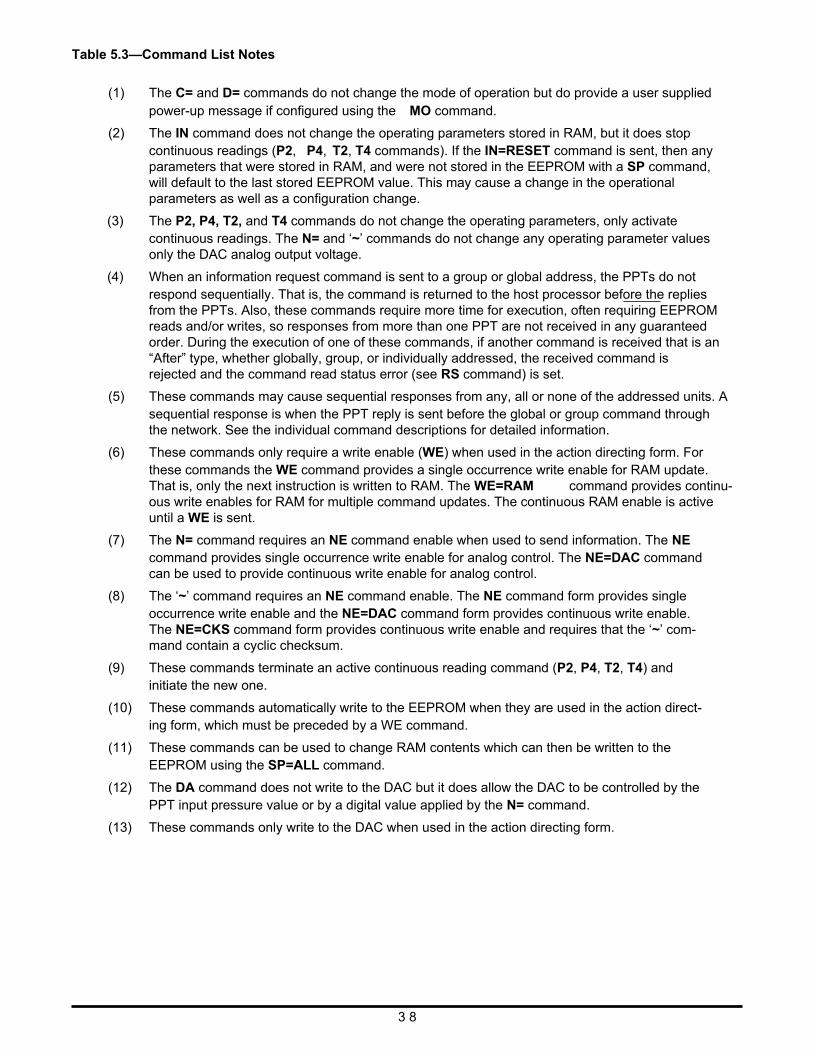
Table 5.3—Command List Notes
(1) The C= and D= commands do not change the mode of operation but do provide a user supplied power-up message if configured using the MO command.
(2) The IN command does not change the operating parameters stored in RAM, but it does stop continuous readings (P2, P4, T2, T4 commands). If the IN=RESET command is sent, then any parameters that were stored in RAM, and were not stored in the EEPROM with a SP command, will default to the last stored EEPROM value. This may cause a change in the operational parameters as well as a configuration change.
(3) The P2, P4, T2, and T4 commands do not change the operating parameters, only activate continuous readings. The N= and ‘~’ commands do not change any operating parameter values only the DAC analog output voltage.
(4) When an information request command is sent to a group or global address, the PPTs do not respond sequentially. That is, the command is returned to the host processor before the replies from the PPTs. Also, these commands require more time for execution, often requiring EEPROM reads and/or writes, so responses from more than one PPT are not received in any guaranteed order. During the execution of one of these commands, if another command is received that is an “After” type, whether globally, group, or individually addressed, the received command is rejected and the command read status error (see RS command) is set.
(5) These commands may cause sequential responses from any, all or none of the addressed units. A sequential response is when the PPT reply is sent before the global or group command through the network. See the individual command descriptions for detailed information.
(6) These commands only require a write enable (WE) when used in the action directing form. For these commands the WE command provides a single occurrence write enable for RAM update. That is, only the next instruction is written to RAM. The WE=RAM command provides continu- ous write enables for RAM for multiple command updates. The continuous RAM enable is active until a WE is sent.
(7) The N= command requires an NE command enable when used to send information. The NE command provides single occurrence write enable for analog control. The NE=DAC command can be used to provide continuous write enable for analog control.
(8) The ‘~’ command requires an NE command enable. The NE command form provides single occurrence write enable and the NE=DAC command form provides continuous write enable. The NE=CKS command form provides continuous write enable and requires that the ‘~’ com- mand contain a cyclic checksum.
(9) These commands terminate an active continuous reading command (P2, P4, T2, T4) and initiate the new one.
(10) These commands automatically write to the EEPROM when they are used in the action direct- ing form, which must be preceded by a WE command.
(11) These commands can be used to change RAM contents which can then be written to the EEPROM using the SP=ALL command.
(12) The DA command does not write to the DAC but it does allow the DAC to be controlled by the PPT input pressure value or by a digital value applied by the N= command.
(13) These commands only write to the DAC when used in the action directing form.
3 8
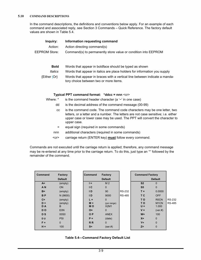
5.10 COMMAND DESCRIPTIONS
In the command descriptions, the definitions and conventions below apply. For an example of each command and associated reply, see Section 3 Commands – Quick Reference. The factory default values are shown in Table 5.4.
Inquiry: Information requesting command
Action: Action directing command(s)
EEPROM Store: Command(s) to permanently store value or condition into EEPROM Bold Words that appear in boldface should be typed as shown
Italics Words that appear in italics are place holders for information you supply
{Either |Or} Words that appear in braces with a vertical line between indicate a manda- tory choice between two or more items.
Typical PPT command format: *ddcc = nnn <cr>
Where: * is the command header character (a ‘~’ in one case)
dd is the decimal address of the command message (00-99)
cc is the command code. The command code characters may be one letter, two letters, or a letter and a number. The letters are not case sensitive; i.e. either upper case or lower case may be used. The PPT will convert the character to upper case.
= equal sign (required in some commands)
nnn additional characters (required in some commands)
<cr> carriage return (ENTER key) must follow every command.
Commands are not executed until the carriage return is applied; therefore, any command message may be re-entered at any time prior to the carriage return. To do this, just type an ‘*’ followed by the remainder of the command.
Command
Factory
Default
Command Factory
Default
Command Factory
Default
A=
A N
(empty)
ON
I =
I C
M 2
0
S2
S5
0
0
B=
B P
C= D = D A
D O
D S
D U
F =
H =
(empty)
N (9600)
(empty) (empty) B
E0N
00S0
PSI
0
100
I D
I D
L = M = M O
O=
O P
P =
R R
S=
90
9000
0 (psi range) X2M1
0
ANEX
(date)
0
(ser.#)
RS-232
RS-485
T =
T C
T O T O U =
V =
W=
X=
Y=
Z=
0.0000
OFF
R0CN RS-232 M1CN RS-485 1.000
(ver.#)
100
0
0
0
Table 5.4—Command Factory Default List
3 9
A= Data String A The A= data string command can be used to store and retrieve up to eight characters in the EEPROM. This command must have 1 to 8 characters immediately following the ‘=’ character. The message is terminated with the <cr> (ENTER key) character. The data string is automatically stored in EEPROM with this action command. Since this string is stored in EEPROM, it will remain in the PPT even after the power is turned off. Examples include dates for maintenance checks, over/under range pressure or temperature values, or key pressure readings specific to application. If the response has an ‘!’ character instead of ‘=‘, there was an EEPROM parity error.
Note: This command will not work when a *ddWE=RAM continuous write enable is active. It must be preceded by a singular write enable (*ddWE).
Inquiry: *ddA= Action: *ddWE
*ddA=Your_msg Your_msg must have 1 to 8 characters immediately following the ‘=’ character. The message is
terminated with the <cr> character. The legal characters for Your_msg include all characters between the ‘space’ (SP) and lower case ‘z’ inclusive, except the ‘*’, in standard ASCII (see last page of manual).
A N Analog Range Setting
The AN command turns on and off the custom ANalog output setting of the DAC. The analog range setting is established with the H= and L= commands. Analog window settings are established with the O= and W= commands. When AN is ON, the customized settings are activated; when OFF, the factory default range of 0V to 5V is active. When custom H= and L= range settings are used, the resolution of the analog signal will be reduced. For example, the full 5 volt range has a 12 bit resolu- tion. A range reduction to 2.5 volts will result in an 11 bit resolution. Ranges between these two values would result in a resolution between 11 and 12 bits. The use of analog window limits O= and W= can increase the resolution of the analog signal. See Section 4.5 for an example. (Default: AN=ON)
Inquiry: *ddAN Action: *ddWE
* d d A N = { O N | O F F| O N -| O F F - }
EEPROM Store: *ddWE
*ddSP=ALL O N The analog output will adjust to the high and low limits (H=, L=) and the offset and
window limits (O=, W=). The highest pressure produces the high (H=) output voltage and the lowest pressure produces the low (L=) voltage.
O F F The analog output will set to 5 volts for the FS pressure (F=) and to 0 volts for zero pressure - or negative FS pressure for differential.
ON- Same function as ON, but output scale is reversed. i.e. The highest pressure produces the low (L=) output voltage and the lowest pressure produces the high (H=) voltage.
OFF- The analog output will set to 0 volts for the FS pressure (F=) and to 5 volts for zero pressure - or negative FS pressure for differential.
4 0
B= Data String B The B= data string command can be used to store and retrieve up to eight characters in the EEPROM. This command must have 1 to 8 characters immediately following the ‘=’ character. The message is terminated with the <cr> (ENTER key) character. The data string is automatically stored in EEPROM with this action command. Since this string is stored in EEPROM, it will remain in the PPT even after the power is turned off. Examples include dates for maintenance checks, over/under range pressure or temperature values, or key pressure readings specific to application. If the re- sponse has an ‘!’ character instead of ‘=‘, there was an EEPROM parity error.
Note: This command will not work when a *ddWE=RAM continuous write enable is active. It must be preceded by a singular write enable (*ddWE).¡
Inquiry: *ddB= Action: *ddWE
*ddB=Your_msg Your_msg must have 1 to 8 characters immediately following the ‘=’ character. The message is
terminated with the <cr> character. The legal characters for Your_msg include all characters between the ‘space’ (SP) and lower case ‘z’ inclusive, except the ‘*’, in standard ASCII (see last page of manual).
B P Baud Rate and Parity Setting
The Baud rate and Parity command is used to change the baud rate and parity type. Both the write enable (WE) and BP command must be sent as a global address (e.g. *99); otherwise, the command is rejected and sets the read status (RS) command error.
For this command only the first one or two baud rate characters need to be used. This command causes the new baud rate and parity setting to be changed and the command to be retransmitted to the next PPT. When the command transmission is complete, the new baud rate and parity are activated, but are not permanently stored in the EEPROM until an SP=All command is executed. The new baud rate must be selected before executing the SP=ALL command. (Default: BP=N9600)
Note: When shipped from the factory, the PPT is set to a baud rate of 9600, 1 start bit, 8 data bits, no parity, and 1 stop bit. If the baud rate has been changed to an unknown value, it will be necessary to search all the baud rate values to reestablish communication.
Inquiry: *ddBP
Response: #ddBP=N or #ddBP=E or #ddBP=O
EEPROM Store: *99WE
*99SP=ALL
Note: A *99WE and *99BP=.. global address must be used to change the baud rate.
Action: *99WE
*99BP= {N|E|O} {1200 |24 00|4800|9600|14400|19 200|28800} N No parity E Even parity O Odd parity
1200,...28800 Baud rate (bits/sec)
4 1
C= Data String C The C= data string command can be used to store and retrieve up to eight characters in the EEPROM. This command must have 1 to 8 characters immediately following the ‘=’ character. The message is terminated with the <cr> (ENTER key) character. The data string is automatically stored in EEPROM with this action command. Since this string is stored in EEPROM, it will remain in the PPT even after the power is turned off. Examples include dates for maintenance checks, over/under range pressure or temperature values, or key pressure readings specific to application. If the response has an ‘!’ character instead of ‘=‘, there was an EEPROM parity error.
Note: This command will not work when a *ddWE=RAM continuous write enable is active. It must be preceded by a singular write enable (*ddWE).
Note: This data can be used to provide the first eight characters of a user provided start-up message (see the MO command). When used as a start-up message, any space character in the C= message will terminate the message. Use an underscore (_) character for spaces.
Inquiry: *dd C= Action: *ddWE
*ddC=Your_msg Your_msg must have 1 to 8 characters immediately following the ‘=’ character. The message is
terminated with the <cr> character. The legal characters for Your_msg include all characters between the ‘space’ (SP) and lower case ‘z’ inclusive, except the ‘*’, in standard ASCII (see last page of manual).
C K Check EEPROM
The ChecK EEPROM command performs a checksum on both the characterization area and the configuration area of the EEPROM. This check typically takes 180 msec.
Inquiry: *ddCK
There are four possible responses for this command.
#(or ?)ddCK=OK #(or ?)ddCK=ERR1 #(or ?)ddCK=ERR2 #(or ?)ddCK=ERR3
Indicates no checksum errors Indicates a characterization area checksum error Indicates a configuration area checksum error Indicates both checksum errors
4 2
D = Data String D The D= data string command can be used to store and retrieve up to eight characters in the EEPROM. This command must have 1 to 8 characters immediately following the ‘=’ character. The message is terminated with the <cr> (ENTER key) character. The data string is automatically stored in EEPROM with this action command. Since this string is stored in EEPROM, it will remain in the PPT even after the power is turned off. Examples include dates for maintenance checks, over/under range pressure or temperature values, or key pressure readings specific to application. If the re- sponse has an ‘!’ character instead of ‘=‘, there was an EEPROM parity error.
Note: This command will not work when a *ddWE=RAM continuous write enable is active. It must be preceded by a singular write enable (*ddWE).
Note: This data can be used to provide the last eight characters of a user provided start-up message (see the MO command). When used as a start-up message, any space character in the D= message will terminate the message. Use an underscore (_) character for spaces.
Inquiry: *ddD= Action: *ddWE
*ddD=Your_msg Your_msg must have 1 to 8 characters immediately following the ‘=’ character. The message is
terminated with the <cr> character. The legal characters for Your_msg include all characters between the ‘space’ (SP) and lower case ‘z’ inclusive, except the ‘*’, in standard ASCII (see last page of manual).
4 3
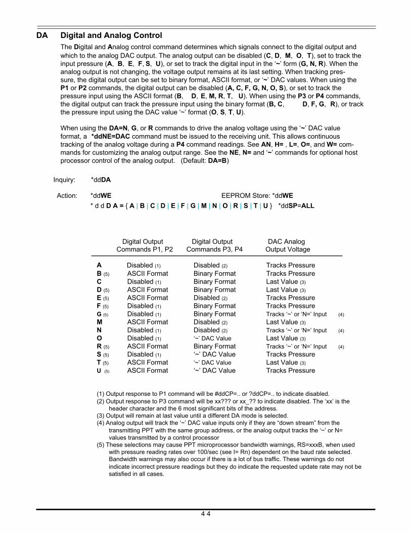
DA Digital and Analog Control The Digital and Analog control command determines which signals connect to the digital output and which to the analog DAC output. The analog output can be disabled (C, D, M, O, T), set to track the input pressure (A, B, E, F, S, U), or set to track the digital input in the ‘~’ form (G, N, R). When the analog output is not changing, the voltage output remains at its last setting. When tracking pres- sure, the digital output can be set to binary format, ASCII format, or ‘~’ DAC values. When using the P1 or P2 commands, the digital output can be disabled (A, C, F, G, N, O, S), or set to track the pressure input using the ASCII format (B, D, E, M, R, T, U). When using the P3 or P4 commands, the digital output can track the pressure input using the binary format (B, C, D, F, G, R), or track the pressure input using the DAC value ‘~’ format (O, S, T, U).
When using the DA=N, G, or R commands to drive the analog voltage using the ‘~’ DAC value format, a *ddNE=DAC command must be issued to the receiving unit. This allows continuous tracking of the analog voltage during a P4 command readings. See AN, H= , L=, O=, and W= com- mands for customizing the analog output range. See the NE, N= and ‘~’ commands for optional host processor control of the analog output. (Default: DA=B)
Inquiry: *ddDA Action: *ddWE
EEPROM Store: *ddWE
* d d D A = { A | B | C | D | E | F | G | M | N | O | R | S | T | U } *ddSP=ALL Digital Output
Digital Output
DAC Analog
A
Commands P1, P2 Commands P3, P4
Disabled (1) Disabled (2)
Output Voltage
Tracks Pressure B (5)
C D (5)
E (5)
F (5)
G (5)
M N O R (5)
S (5)
T (5)
U (5)
ASCII Format Disabled (1)
ASCII Format ASCII Format Disabled (1)
Disabled (1)
ASCII Format Disabled (1)
Disabled (1)
ASCII Format Disabled (1)
ASCII Format ASCII Format
Binary Format Binary Format Binary Format Disabled (2)
Binary Format Binary Format Disabled (2)
Disabled (2)
‘~’ DAC Value Binary Format ‘~’ DAC Value ‘~’ DAC Value ‘~’ DAC Value
Tracks Pressure Last Value (3)
Last Value (3)
Tracks Pressure Tracks Pressure Tracks ‘~’ or ‘N=’ Input (4)
Last Value (3)
Tracks ‘~’ or ‘N=’ Input (4)
Last Value (3)
Tracks ‘~’ or ‘N=’ Input (4)
Tracks Pressure Last Value (3)
Tracks Pressure
(1) Output response to P1 command will be #ddCP=.. or ?ddCP=.. to indicate disabled. (2) Output response to P3 command will be xx??? or xx_?? to indicate disabled. The ‘xx’ is the
header character and the 6 most significant bits of the address. (3) Output will remain at last value until a different DA mode is selected. (4) Analog output will track the ‘~’ DAC value inputs only if they are “down stream” from the
transmitting PPT with the same group address, or the analog output tracks the ‘~’ or N= values transmitted by a control processor
(5) These selections may cause PPT microprocessor bandwidth warnings, RS=xxxB, when used with pressure reading rates over 100/sec (see I= Rn) dependent on the baud rate selected. Bandwidth warnings may also occur if there is a lot of bus traffic. These warnings do not indicate incorrect pressure readings but they do indicate the requested update rate may not be satisfied in all cases.
4 4
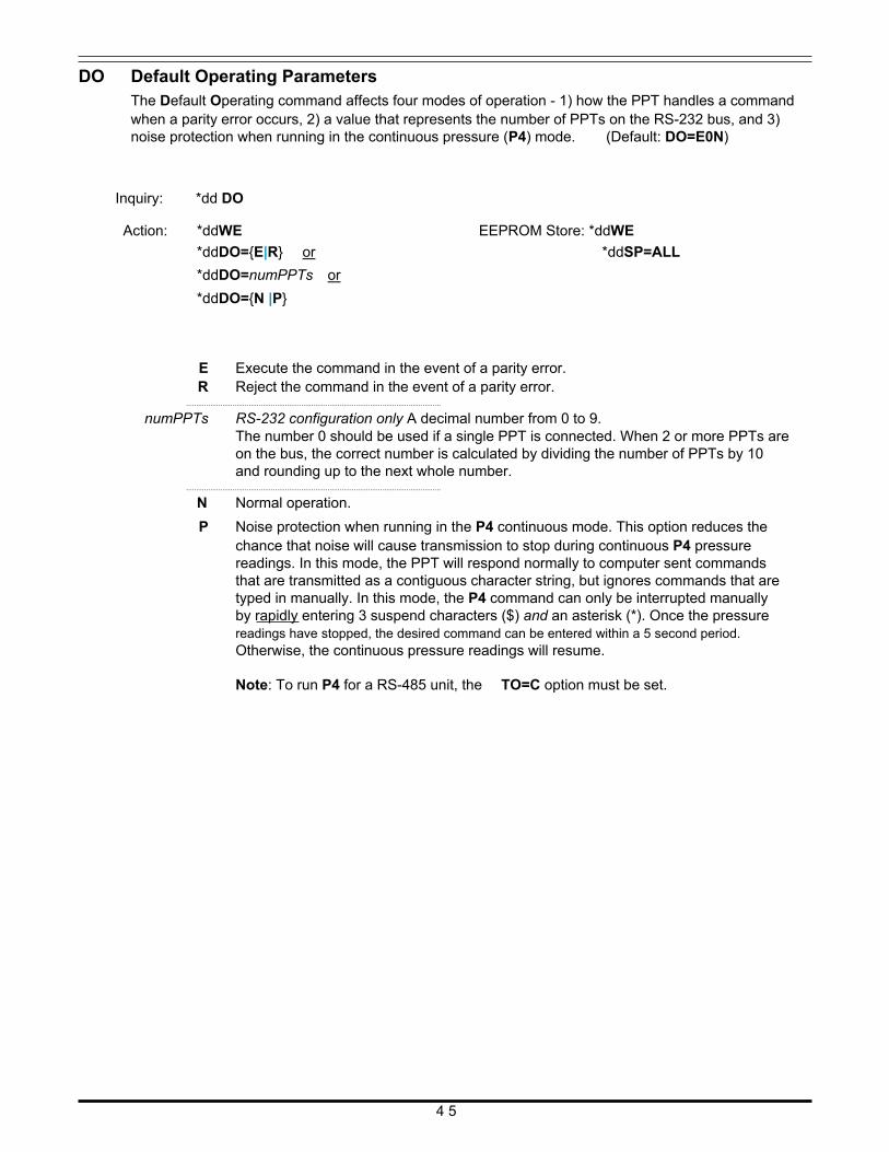
DO Default Operating Parameters The Default Operating command affects four modes of operation - 1) how the PPT handles a command when a parity error occurs, 2) a value that represents the number of PPTs on the RS-232 bus, and 3) noise protection when running in the continuous pressure (P4) mode. (Default: DO=E0N)
Inquiry: *dd DO
Action: *ddWE
*ddDO={E|R} or
*ddDO=numPPTs or
*ddDO={N |P}
EEPROM Store: *ddWE
*ddSP=ALL
E Execute the command in the event of a parity error. R Reject the command in the event of a parity error.
..............................................................................................................................
numPPTs RS-232 configuration only A decimal number from 0 to 9. The number 0 should be used if a single PPT is connected. When 2 or more PPTs are on the bus, the correct number is calculated by dividing the number of PPTs by 10 and rounding up to the next whole number.
..............................................................................................................................
N Normal operation.
P Noise protection when running in the P4 continuous mode. This option reduces the chance that noise will cause transmission to stop during continuous P4 pressure readings. In this mode, the PPT will respond normally to computer sent commands that are transmitted as a contiguous character string, but ignores commands that are typed in manually. In this mode, the P4 command can only be interrupted manually by rapidly entering 3 suspend characters ($) and an asterisk (*). Once the pressure readings have stopped, the desired command can be entered within a 5 second period. Otherwise, the continuous pressure readings will resume.
Note: To run P4 for a RS-485 unit, the TO=C option must be set.
4 5
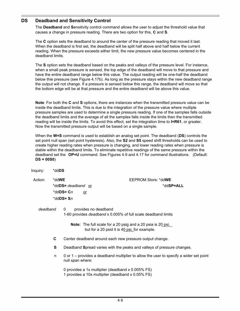
DS Deadband and Sensitivity Control The Deadband and Sensitivity control command allows the user to adjust the threshold value that causes a change in pressure reading. There are two option for this, C and S.
The C option sets the deadband to around the center of the pressure reading that moved it last. When the deadband is first set, the deadband will be split half above and half below the current reading. When the pressure exceeds either limit, the new pressure value becomes centered in the deadband limits.
The S option sets the deadband based on the peaks and valleys of the pressure level. For instance, when a small peak pressure is sensed, the top edge of the deadband will move to that pressure and have the entire deadband range below this value. The output reading will be one-half the deadband below thie pressure (see Figure 4.17b). As long as the pressure stays within the new deadband range the output will not change. If a pressure is sensed below this range, the deadband will move so that the bottom edge will be at that pressure and the entire deadband will be above this value.
Note: For both the C and S options, there are instances when the transmitted pressure value can be inside the deadband limits. This is due to the integration of the pressure value where multiple pressure samples are used to determine a single pressure reading. If one of the samples falls outside the deadband limits and the average of all the samples falls inside the limits then the transmitted reading will be inside the limits. To avoid this effect, set the integration time to I=R61, or greater. Now the transmitted pressure output will be based on a single sample.
When the W=S command is used to establish an analog set point. The deadband (DS) controls the set point null span (set point hysteresis). Also, the S2 and S5 speed shift thresholds can be used to create higher reading rates when pressure is changing, and lower reading rates when pressure is stable within the deadband limits. To eliminate repetitive readings of the same pressure within the deadband set the OP=U command. See Figures 4.9 and 4.17 for command illustrations. (Default: DS = 00S0)
Inquiry: *ddDS Action: *ddWE
*ddDS= deadband or
*ddDS= Cn or
*ddDS= Sn
deadband 0 provides no deadband
EEPROM Store: *ddWE
*ddSP=ALL
1-60 provides deadband x 0.005% of full scale deadband limits
Note: The full scale for a 20 psig and a 20 psia is 20 psi, but for a 20 psid it is 40 psi, for example.
C Center deadband around each new pressure output change. S Deadband Spread varies with the peaks and valleys of pressure changes. n 0 or 1 – provides a deadband multiplier to allow the user to specify a wider set point
null span where:
0 provides a 1x multiplier (deadband x 0.005% FS) 1 provides a 10x multiplier (deadband x 0.05% FS)
4 6
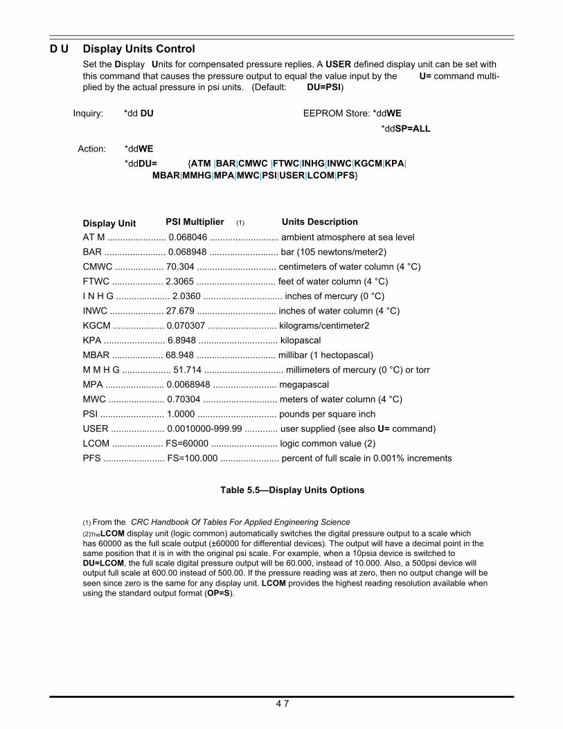
D U Display Units Control Set the Display Units for compensated pressure replies. A USER defined display unit can be set with this command that causes the pressure output to equal the value input by the U= command multi- plied by the actual pressure in psi units. (Default: DU=PSI)
Inquiry: *dd DU
Action: *ddWE
*ddDU=
EEPROM Store: *ddWE
*ddSP=ALL
{ATM |BAR|CMWC |FTWC|INHG|INWC|KGCM|KPA| Display Unit
MBAR|MMHG|MPA|MWC|PSI|USER|LCOM|PFS}
PSI Multiplier (1) Units Description
AT M ....................... 0.068046 ........................... ambient atmosphere at sea level
BAR ........................ 0.068948 ........................... bar (105 newtons/meter2)
CMWC ................... 70.304 ............................... centimeters of water column (4 °C)
FTWC .................... 2.3065 ............................... feet of water column (4 °C)
I N H G ..................... 2.0360 ............................... inches of mercury (0 °C)
INWC ..................... 27.679 ............................... inches of water column (4 °C)
KGCM .................... 0.070307 ........................... kilograms/centimeter2
KPA ........................ 6.8948 ............................... kilopascal
MBAR .................... 68.948 ............................... millibar (1 hectopascal)
M M H G ................... 51.714 ............................... millimeters of mercury (0 °C) or torr
MPA ....................... 0.0068948 ......................... megapascal
MWC ...................... 0.70304 ............................. meters of water column (4 °C)
PSI ......................... 1.0000 ............................... pounds per square inch
USER ..................... 0.0010000-999.99 ............. user supplied (see also U= command)
LCOM .................... FS=60000 .......................... logic common value (2)
PFS ........................ FS=100.000 ....................... percent of full scale in 0.001% increments Table 5.5—Display Units Options
(1) From the CRC Handbook Of Tables For Applied Engineering Science (2)TheLCOM display unit (logic common) automatically switches the digital pressure output to a scale which has 60000 as the full scale output (±60000 for differential devices). The output will have a decimal point in the same position that it is in with the original psi scale. For example, when a 10psia device is switched to DU=LCOM, the full scale digital pressure output will be 60.000, instead of 10.000. Also, a 500psi device will output full scale at 600.00 instead of 500.00. If the pressure reading was at zero, then no output change will be seen since zero is the same for any display unit. LCOM provides the highest reading resolution available when using the standard output format (OP=S).
4 7
F=
Customized Full Scale Range The F= command is used in conjunction with the X=, Y=, and Z= command to customize the full scale range and user compensation of the PPT. The F= command allows the user to reduce the full scale range of the PPT by at least one-half the FS value (M=). Some units may allow more than 2x reduction of the full scale value. The F= command value can have up to 5 significant digits with a decimal point. Enter an F=0 command to disable this function and return to the factory default (M=) full scale value. Using the F= command, the maximum allowable full scale pressure is the M= value and the minimum allowable FS pressure is (0.5 x the M= value). The new F= value becomes the standard FS number used for other commands and range calculations. (Default: F=0 , factory set FS)
Note: The accuracy specification is always referenced to the factory (M=) full scale value. Note: After the F= command is changed, make sure all parameters are stored in EEPROM (SP=ALL) then enter a reset command (IN=RESET) or cycle the power off and on.
Inquiry: *ddF=
Note: The F= inquiry will always send the full scale value in the display units (DU) that were set when the F= command was executed. To insure the pressure units of an F= inquiry, follow the F= command with the DU inquiry.
Action: *ddWE EEPROM Store: *ddWE
*ddF=FSnum *ddSP=ALL FSnum This value can have up to 5 significant digits with a decimal point. First, select the display
units desired (except for LCOM, USER, or PFS) using the DU command.
H= Highest Analog Voltage Set the DAC High analog output voltage full scale (FS) reading. The input is a value from 0 to 99% of 5 volts, or 50 millivolts per count. An H= inquiry reads the value in 50 millivolt counts. This command is used in conjunction with the L=, and AN commands to customize the range of the PPT analog voltage output. If there is an input error, then the command error flag in the RS command will be set and no change will occur. See Figure 4.4 for command illustration. (Default: H=100)
Note: See the L= command for setting the low analog output voltage. See the AN command for enabling and disabling the H= and L= settings and for the effect on analog resolution. If H= value - L= value, then no change will occur and an RS command error will result.
Inquiry: *ddH= Action: *ddWE
*ddH=pp
EEPROM Store: *ddWE
*ddSP=ALL pp 0 - 100 (%) This number sets the full scale (FS) analog voltage as an integer percent of 5.00
volts. An H=0 setting will set the high level to 100% (5 volts). It can also be thought of as a multiplier in 50 millivolt increments. As an example, H=85 corresponds to a FS voltage of 4.25 volt (85 x 50mV or 85% of 5.00V). For H=0, the FS voltage is set to 100%, or 5.00 volts. A H= entry greater than 100 will set H=100.
4 8
I= I C
Integration Time The Integration time command allows the user to adjust the analog-to-digital converter integration time over a range of 1 sample every 12 seconds up to 120 samples per second. The integration time can be used to filter noisy pressure inputs by averaging, or smoothing, the readings over a selected period of time. See Figures 4.13 and 4.14.
The integration time can be set within a range of 1 to 120 samples/sec using the I=Rn form or a range of 100msec to 12 sec/sample using the I=Mn form. The values for ‘n’ range from 0 to 120 for the rate (Rn) and millisecond (Mn) form. For I=R0, or I=M0, the last stored setting in EEPROM will be restored. If there is an input error, then the command error flag in the RS command will be set and no change will occur. (Default: I = M2 [200msec = 5 readings/sec])
Inquiry: *ddI= Action: *ddWE EEPROM Store: *ddWE
*ddI= Rn or Mn *dd SP=ALL
R n where n = 0 - 120. This form sets the output Rate to integer values between 1 and 120 readings per second. When using the Rn form, the sample rates do not utilize the S2, S5, and IC commands. I=R0 will restore the last setting saved in EEPROM.
..............................................................................................................................
M n where n = 0 - 120. This form sets the output sample time in 100 Millisecond incre- ments (0.1 seconds). This allows output rates from 10 readings per second up to 1 reading every 12 seconds. I=M0 will restore the last setting saved in EEPROM.
Idle Count Parameter The Idle Count parameter specifies the number of pressure integration times that the microproces- sor skips between output values (see Fig. 4.18). This command is only operational for the I=Mn form of the Integration Time (I=) command. (See the I= command for setting integration times.) This parameter can be used to reduce the average PPT power requirement by as much as 50% when increased response time is acceptable. This parameter is also used to reduce the reply message traffic on the network bus from PPTs whose response time is not critical. The S2 and S5 parameters are operational with this parameter to allow integration speed shifting. (Default: IC=0)
Note: If the OP=W (watchdog timer) command is set, then the IC command will not work (other than IC=0) and cause a RS command error condition.
Inquiry: *ddIC Action: *ddWE EEPROM Store: *ddWE
*ddIC= ICcount *dd SP=ALL ICcount 0 to 255
where: 0 causes all integration cycles to be used. 1 causes 1 of 2 integration cycles to be used. 2 causes 1 of 3 integration cycles to be used. 3 causes 1 of 4 integration cycles to be used.
255 causes 1 of 256 integration cycles to be used.
4 9
I D Identification Number Set the device IDentification number. This command is used to set a unique PPT address and/or a group address. Two sections describe this command based on the RS-232 or RS-485 type of unit. (Default: device ID=00, group address=90)
RS-232 type only
To unassign all device IDs, send a *99WE and a *99ID=00 command. In this case, all the PPT units in the network will set their device IDs to address ‘00’, the null address.
To sequentially assign device IDs to a RS-232 ring network, send a *99ID=01 to the first unit. That unit will number itself ID=01, increment the command and automatically send a *99ID=02 to the next PPT in line. This will continue down the ring until all of the PPTs have sequentially numbered themselves. The host processor will receive: *99ID=nn, where nn= the number of PPT units in the network plus 1. For example, if 6 PPTs are connected in a network, then a *99ID=01 command will sequentially assign device IDs to all six units and return a *99ID=07 to the host processor. Note that ID=01 must be entered and not just ID=1. The PPTs will now be sequentially assigned device IDs from 01 to 06.
Inquiry: *ddID (reply is group number) Action: *ddWE
*ddID=newNumber
EEPROM Store: *ddWE
*ddSP=ALL
newNumber 00 – 99 (must enter a TWO digit decimal number)
where: 00 Unit numbers itself ‘00’ (null address) and transmits the message unchanged. A *99ID=00 will change all PPTs in network to null address (see Note above).
01-88 Unit numbers itself with device ID newNumber, increments the number by 1, and transmits the message. This will sequentially number all PPTs in a network, starting from unit dd, with ID=newNumber (see Note above).
89 Unit numbers itself with device ID ‘89’, changes the number to ‘99’, and transmits the message.
90-98 Unit assigns itself group address newNumber, and transmits the message un- changed.
99 Unit does not change its address, changes newNumber to ‘ER’ and transmits the message.
ER Unit does not change its address and transmits the message unchanged.
RS-485 type only
If a RS-485 unit has the factory default identification address of 00, the PPT can not respond to group or global commands until it is assigned a valid address. This can be accomplished by one of three methods:
1) An identification address can be assigned off-line by connecting the PPT to an RS-485 compatible serial port. The command sequence to assign address 01 is:
*00WE *00ID=01 *01WE *01SP=ALL
If global addressing is to be used for PPT responses, then all PPT’s that are to respond to global requests must be addressed sequentially starting with address 01. See the TO command description for further information on RS-485 global addressing.
5 0
If group addressing is to be used for PPT responses, then all PPT’s within a single group must have a group sub-addresses assigned sequentially starting with address 01. The command sequence to assign group address 91 and sub-address 01 to a PPT with identification address 03 is:
*03WE *03ID=9101 *03WE *03SP=ALL
See the TO command description for further information on RS-485 global addressing.
2) If the PPTs to receive ID addresses have null addresses, they can be installed on the RS-485 bus one at a time. After each PPT is connected, its ID address can be assigned by using the above proce- dure.
3) Any number of null addressed, or unknown addressed, PPTs can be connected to a RS-485 bus and have ID individually assigned by using their serial numbers as unique identifiers. The command sequence to assign the address 02 to a PPT with serial number 3175 is:
*99WE *99S=00003175 (must use all 8 numbers) *99WE *99ID=02 *02WE *02SP=ALL
When the identification address has been assigned, group address and sub-address can be assigned in the same manner as in 1) above.
Note: For RS-485 units, all *9xID= commands are ignored unless the command has been preceded by a serial number command (*99S=ssssssss) with the serial number that matches that unit. The next *9xID command will set that unit’s device ID number.
I N Initialize PPT Microprocessor
This command INitializes the PPT microprocessor. When this command is sent with the RESET option, it performs the same start-up function as removing and re-applying power to the PPT (excep- tions to this are described in the MO command).
Action: * d dI N
This stops a continuous read operation but does not perform a power-on reset. All RAM stored parameters are retained.
Action: *ddIN=RESET
This stops any current operation and then performs a power-on reset. If the command has a group or global address (90-99), the message is re-transmitted before the power-on reset is activated. All RAM parameters are replaced with EEPROM stored parameters. See MO command for reset options.
5 1
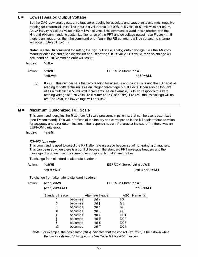
L = Lowest Analog Output Voltage Set the DAC Low analog output voltage zero reading for absolute and gauge units and most negative reading for differential units. The input is a value from 0 to 99% of 5 volts, or 50 millivolts per count. An L= inquiry reads the value in 50 millivolt counts. This command is used in conjunction with the H=, and AN commands to customize the range of the PPT analog voltage output –see Figure 4.4. If there is an input error, then the command error flag in the RS command will be set and no change will occur. (Default: L=0 )
Note: See the H= command for setting the high, full scale, analog output voltage. See the AN com- mand for enabling and disabling the H= and L= settings. If L= value • H= value, then no change will occur and an RS command error will result.
Inquiry: *ddL= Action: *ddWE
*ddL=pp
EEPROM Store: *ddWE
*ddSP=ALL pp 0 - 99 This number sets the zero reading for absolute and gauge units and the FS negative
reading for differential units as an integer percentage of 5.00 volts. It can also be thought of as a multiplier in 50 millivolt increments. As an example, L=15 corresponds to a zero reading voltage of 0.75 volts (15 x 50mV or 15% of 5.00V). For L=0, the low voltage will be 0V. For L>99, the low voltage will be 4.95V.
M = Maximum Customized Full Scale This command identifies the Maximum full scale pressure, in psi units, that can be user customized (see F= command). This value is fixed at the factory and corresponds to the full scale reference value for accuracy and error determination. If the response has an ‘!’ character instead of ‘=‘, there was an EEPROM parity error.
Inquiry: * d d M
RS-485 type only This command is used to select the PPT alternate message header set of non-printing characters. This can be used when there is a conflict between the standard PPT message headers and the message characters used by some other components that share the bus.
To change from standard to alternate headers:
Action: *ddWE
*dd M=ALT To change from alternate to standard headers:
Action: (ctrl \) ddWE
(ctrl \) ddM=ALT
EEPROM Store: (ctrl \) ddWE
(ctrl \) ddSP=ALL
EEPROM Store: *ddWE
*ddSP=ALL Standard Header
Alternate Header
ASCII Name (1)
* $ ~ # { } ! @
becomes becomes becomes becomes becomes becomes becomes becomes
ctrl \ ctrl ] ctrl ^ ctrl _ ctrl Q ctrl R ctrl S ctrl T
FS GS RS US DC1 DC2 DC3 DC4
Note: For example, the designator (ctrl \) indicates that the control key, “ctrl”, is held down while the backslash key, “\”, is typed. (1) See Table 9.2 for ASCII values.
5 2
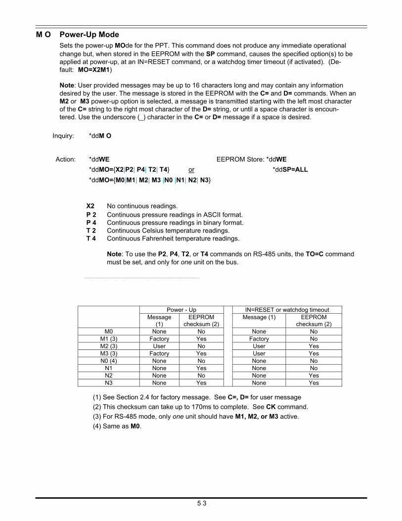
M O Power-Up Mode Sets the power-up MOde for the PPT. This command does not produce any immediate operational change but, when stored in the EEPROM with the SP command, causes the specified option(s) to be applied at power-up, at an IN=RESET command, or a watchdog timer timeout (if activated). (De- fault: MO=X2M1)
Note: User provided messages may be up to 16 characters long and may contain any information desired by the user. The message is stored in the EEPROM with the C= and D= commands. When an M2 or M3 power-up option is selected, a message is transmitted starting with the left most character of the C= string to the right most character of the D= string, or until a space character is encoun- tered. Use the underscore (_) character in the C= or D= message if a space is desired.
Inquiry: *ddM O
Action: *ddWE
*ddMO={X2|P2| P4| T2| T4} or
EEPROM Store: *ddWE
*ddSP=ALL
*ddMO={M0|M1| M2| M3 |N0 |N1| N2| N3}
X2 No continuous readings. P 2 Continuous pressure readings in ASCII format. P 4 Continuous pressure readings in binary format. T 2 Continuous Celsius temperature readings. T 4 Continuous Fahrenheit temperature readings.
Note: To use the P2, P4, T2, or T4 commands on RS-485 units, the TO=C command must be set, and only for one unit on the bus.
..............................................................................................................................
(1) See Section 2.4 for factory message. See C=, D= for user message
(2) This checksum can take up to 170ms to complete. See CK command.
(3) For RS-485 mode, only one unit should have M1, M2, or M3 active.
(4) Same as M0.
5 3
Power - Up IN=RESET or watchdog timeout Message
(1) EEPROM
checksum (2) Message (1) EEPROM
checksum (2) M0 None No None No
M1 (3) Factory Yes Factory No M2 (3) User No User Yes M3 (3) Factory Yes User Yes N0 (4) None No None No
N1 None Yes None No N2 None No None Yes N3 None Yes None Yes
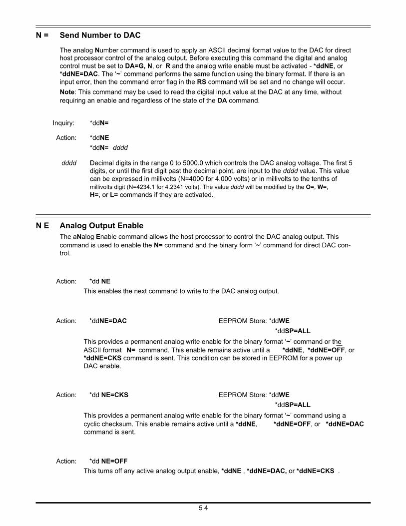
N = Send Number to DAC The analog Number command is used to apply an ASCII decimal format value to the DAC for direct host processor control of the analog output. Before executing this command the digital and analog control must be set to DA=G, N, or R and the analog write enable must be activated - *ddNE, or *ddNE=DAC. The ‘~’ command performs the same function using the binary format. If there is an input error, then the command error flag in the RS command will be set and no change will occur.
Note: This command may be used to read the digital input value at the DAC at any time, without requiring an enable and regardless of the state of the DA command.
Inquiry: *ddN=
Action: *ddNE
*ddN= dddd dddd Decimal digits in the range 0 to 5000.0 which controls the DAC analog voltage. The first 5
digits, or until the first digit past the decimal point, are input to the dddd value. This value can be expressed in millivolts (N=4000 for 4.000 volts) or in millivolts to the tenths of millivolts digit (N=4234.1 for 4.2341 volts). The value dddd will be modified by the O=, W=, H=, or L= commands if they are activated.
N E Analog Output Enable The aNalog Enable command allows the host processor to control the DAC analog output. This command is used to enable the N= command and the binary form ‘~’ command for direct DAC con- trol.
Action: *dd NE
This enables the next command to write to the DAC analog output. Action: *ddNE=DAC
EEPROM Store: *ddWE
*ddSP=ALL
This provides a permanent analog write enable for the binary format ‘~’ command or the ASCII format N= command. This enable remains active until a *ddNE, *ddNE=OFF, or *ddNE=CKS command is sent. This condition can be stored in EEPROM for a power up DAC enable.
Action: *dd NE=CKS
EEPROM Store: *ddWE
*ddSP=ALL
This provides a permanent analog write enable for the binary format ‘~’ command using a cyclic checksum. This enable remains active until a *ddNE, *ddNE=OFF, or *ddNE=DAC command is sent.
Action: *dd NE=OFF
This turns off any active analog output enable, *ddNE , *ddNE=DAC, or *ddNE=CKS . 5 4
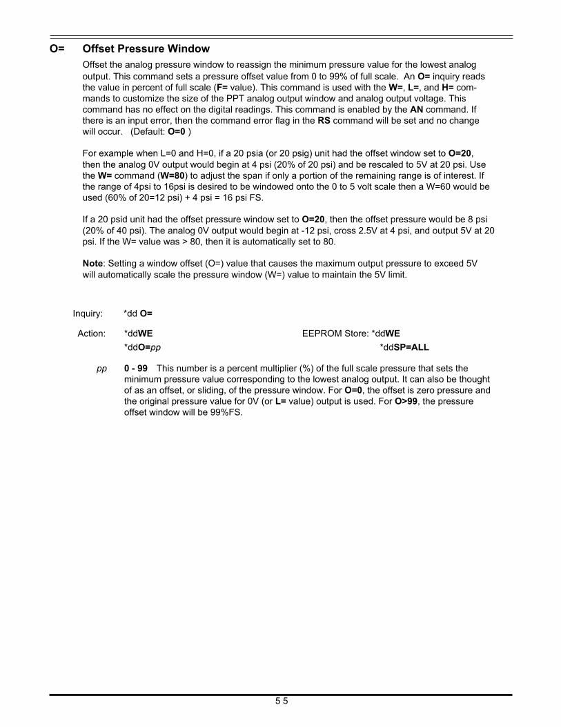
O= Offset Pressure Window Offset the analog pressure window to reassign the minimum pressure value for the lowest analog output. This command sets a pressure offset value from 0 to 99% of full scale. An O= inquiry reads the value in percent of full scale (F= value). This command is used with the W=, L=, and H= com- mands to customize the size of the PPT analog output window and analog output voltage. This command has no effect on the digital readings. This command is enabled by the AN command. If there is an input error, then the command error flag in the RS command will be set and no change will occur. (Default: O=0 )
For example when L=0 and H=0, if a 20 psia (or 20 psig) unit had the offset window set to O=20, then the analog 0V output would begin at 4 psi (20% of 20 psi) and be rescaled to 5V at 20 psi. Use the W= command (W=80) to adjust the span if only a portion of the remaining range is of interest. If the range of 4psi to 16psi is desired to be windowed onto the 0 to 5 volt scale then a W=60 would be used (60% of 20=12 psi) + 4 psi = 16 psi FS.
If a 20 psid unit had the offset pressure window set to O=20, then the offset pressure would be 8 psi (20% of 40 psi). The analog 0V output would begin at -12 psi, cross 2.5V at 4 psi, and output 5V at 20 psi. If the W= value was > 80, then it is automatically set to 80.
Note: Setting a window offset (O=) value that causes the maximum output pressure to exceed 5V will automatically scale the pressure window (W=) value to maintain the 5V limit.
Inquiry: *dd O=
Action: *ddWE
*ddO=pp
EEPROM Store: *ddWE
*ddSP=ALL pp 0 - 99 This number is a percent multiplier (%) of the full scale pressure that sets the
minimum pressure value corresponding to the lowest analog output. It can also be thought of as an offset, or sliding, of the pressure window. For O=0, the offset is zero pressure and the original pressure value for 0V (or L= value) output is used. For O>99, the pressure offset window will be 99%FS.
5 5
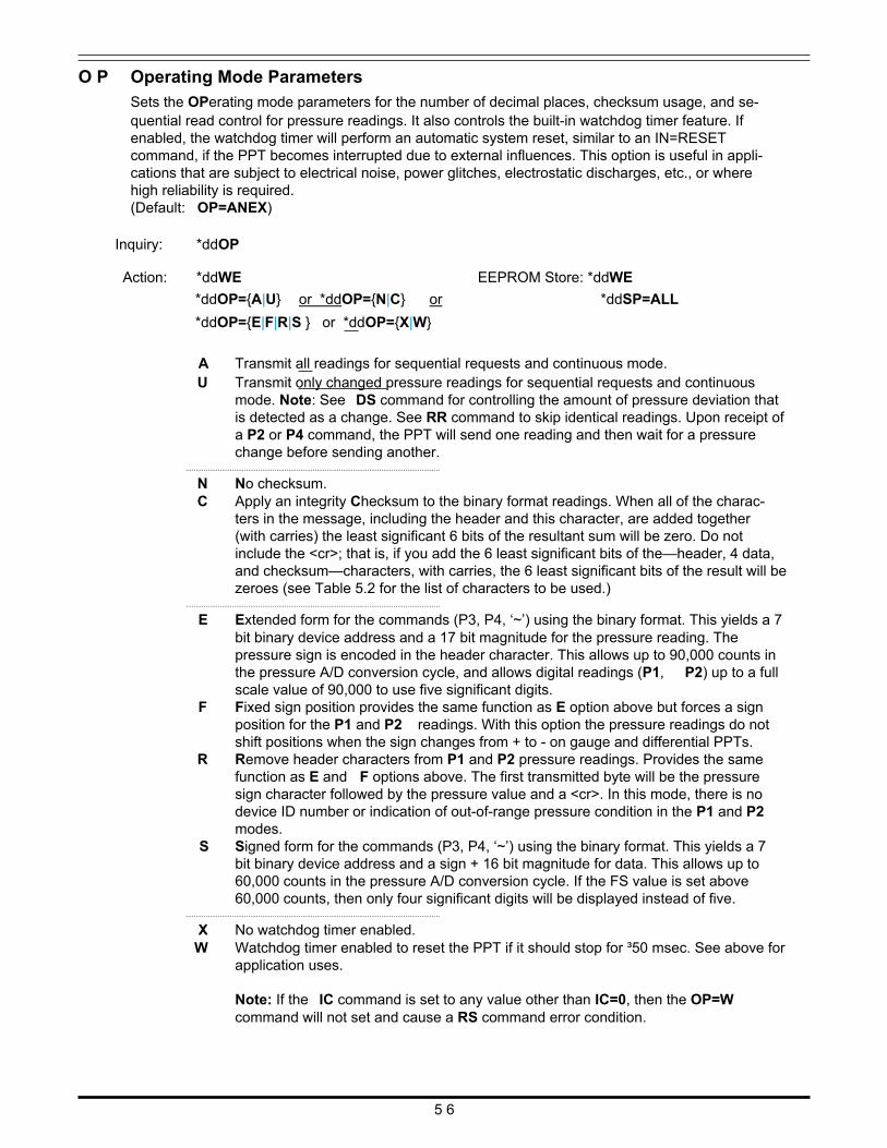
O P Operating Mode Parameters Sets the OPerating mode parameters for the number of decimal places, checksum usage, and se- quential read control for pressure readings. It also controls the built-in watchdog timer feature. If enabled, the watchdog timer will perform an automatic system reset, similar to an IN=RESET command, if the PPT becomes interrupted due to external influences. This option is useful in appli- cations that are subject to electrical noise, power glitches, electrostatic discharges, etc., or where high reliability is required. (Default: OP=ANEX)
Inquiry: *ddOP Action: *ddWE
*ddOP={A|U} or *ddOP={N|C} or
*ddOP={E|F|R|S } or *ddOP={X|W}
EEPROM Store: *ddWE
*ddSP=ALL
A Transmit all readings for sequential requests and continuous mode. U Transmit only changed pressure readings for sequential requests and continuous
mode. Note: See DS command for controlling the amount of pressure deviation that is detected as a change. See RR command to skip identical readings. Upon receipt of a P2 or P4 command, the PPT will send one reading and then wait for a pressure change before sending another.
..............................................................................................................................
N No checksum. C Apply an integrity Checksum to the binary format readings. When all of the charac-
ters in the message, including the header and this character, are added together (with carries) the least significant 6 bits of the resultant sum will be zero. Do not include the <cr>; that is, if you add the 6 least significant bits of the—header, 4 data, and checksum—characters, with carries, the 6 least significant bits of the result will be zeroes (see Table 5.2 for the list of characters to be used.)
..............................................................................................................................
E Extended form for the commands (P3, P4, ‘~’) using the binary format. This yields a 7 bit binary device address and a 17 bit magnitude for the pressure reading. The pressure sign is encoded in the header character. This allows up to 90,000 counts in the pressure A/D conversion cycle, and allows digital readings (P1, P2) up to a full scale value of 90,000 to use five significant digits.
F Fixed sign position provides the same function as E option above but forces a sign position for the P1 and P2 readings. With this option the pressure readings do not shift positions when the sign changes from + to - on gauge and differential PPTs.
R Remove header characters from P1 and P2 pressure readings. Provides the same function as E and F options above. The first transmitted byte will be the pressure sign character followed by the pressure value and a <cr>. In this mode, there is no device ID number or indication of out-of-range pressure condition in the P1 and P2 modes.
S Signed form for the commands (P3, P4, ‘~’) using the binary format. This yields a 7 bit binary device address and a sign + 16 bit magnitude for data. This allows up to 60,000 counts in the pressure A/D conversion cycle. If the FS value is set above 60,000 counts, then only four significant digits will be displayed instead of five.
..............................................................................................................................
X No watchdog timer enabled. W Watchdog timer enabled to reset the PPT if it should stop for ³50 msec. See above for
application uses.
Note: If the IC command is set to any value other than IC=0, then the OP=W command will not set and cause a RS command error condition.
5 6
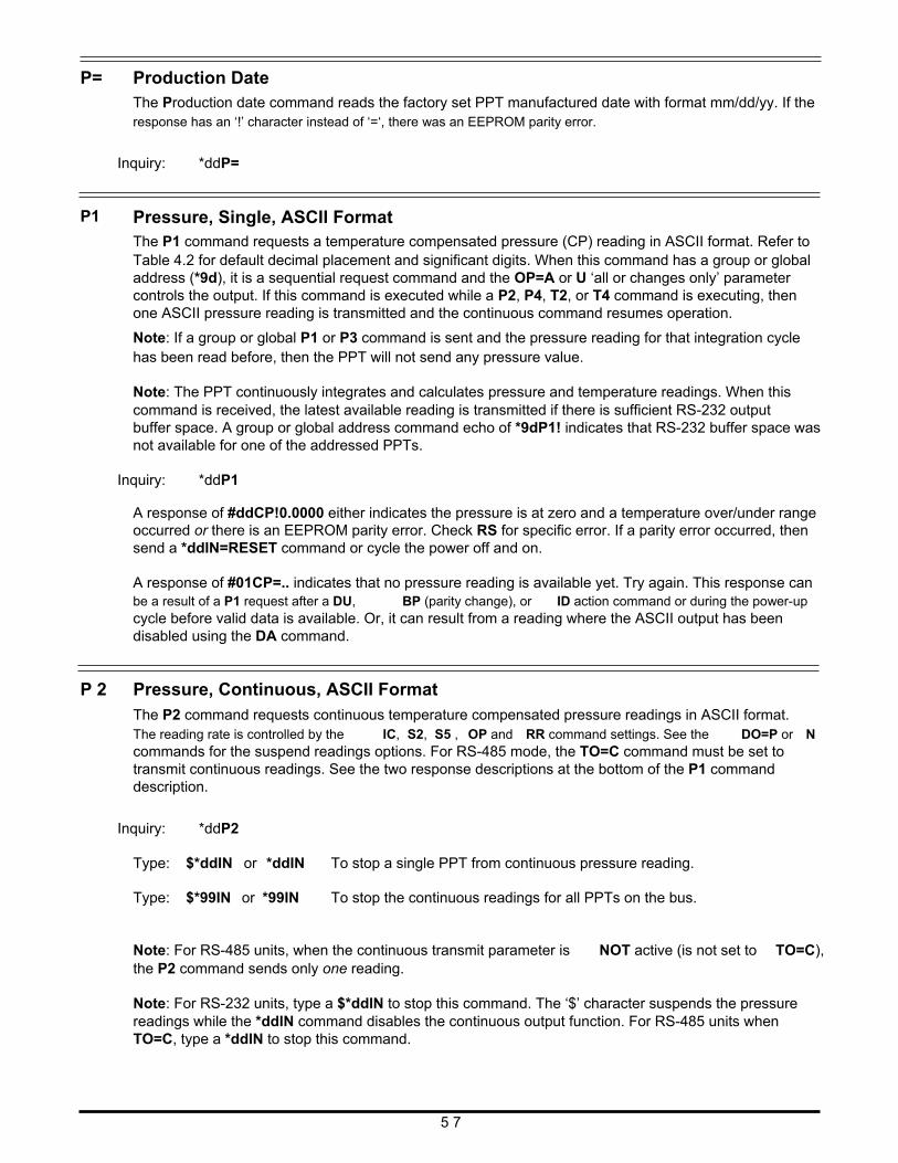
P=
P1
Production Date The Production date command reads the factory set PPT manufactured date with format mm/dd/yy. If the response has an ‘!’ character instead of ‘=‘, there was an EEPROM parity error.
Inquiry: *ddP=
Pressure, Single, ASCII Format The P1 command requests a temperature compensated pressure (CP) reading in ASCII format. Refer to Table 4.2 for default decimal placement and significant digits. When this command has a group or global address (*9d), it is a sequential request command and the OP=A or U ‘all or changes only’ parameter controls the output. If this command is executed while a P2, P4, T2, or T4 command is executing, then one ASCII pressure reading is transmitted and the continuous command resumes operation.
Note: If a group or global P1 or P3 command is sent and the pressure reading for that integration cycle has been read before, then the PPT will not send any pressure value.
Note: The PPT continuously integrates and calculates pressure and temperature readings. When this command is received, the latest available reading is transmitted if there is sufficient RS-232 output buffer space. A group or global address command echo of *9dP1! indicates that RS-232 buffer space was not available for one of the addressed PPTs.
Inquiry: *ddP1 A response of #ddCP!0.0000 either indicates the pressure is at zero and a temperature over/under range occurred or there is an EEPROM parity error. Check RS for specific error. If a parity error occurred, then send a *ddIN=RESET command or cycle the power off and on.
A response of #01CP=.. indicates that no pressure reading is available yet. Try again. This response can be a result of a P1 request after a DU, BP (parity change), or ID action command or during the power-up cycle before valid data is available. Or, it can result from a reading where the ASCII output has been disabled using the DA command.
P 2 Pressure, Continuous, ASCII Format The P2 command requests continuous temperature compensated pressure readings in ASCII format. The reading rate is controlled by the IC, S2, S5 , OP and RR command settings. See the DO=P or N commands for the suspend readings options. For RS-485 mode, the TO=C command must be set to transmit continuous readings. See the two response descriptions at the bottom of the P1 command description.
Inquiry: *ddP2 Type: $*ddIN or *ddIN To stop a single PPT from continuous pressure reading.
Type: $*99IN or *99IN To stop the continuous readings for all PPTs on the bus.
Note: For RS-485 units, when the continuous transmit parameter is NOT active (is not set to TO=C), the P2 command sends only one reading.
Note: For RS-232 units, type a $*ddIN to stop this command. The ‘$’ character suspends the pressure readings while the *ddIN command disables the continuous output function. For RS-485 units when TO=C, type a *ddIN to stop this command.
5 7
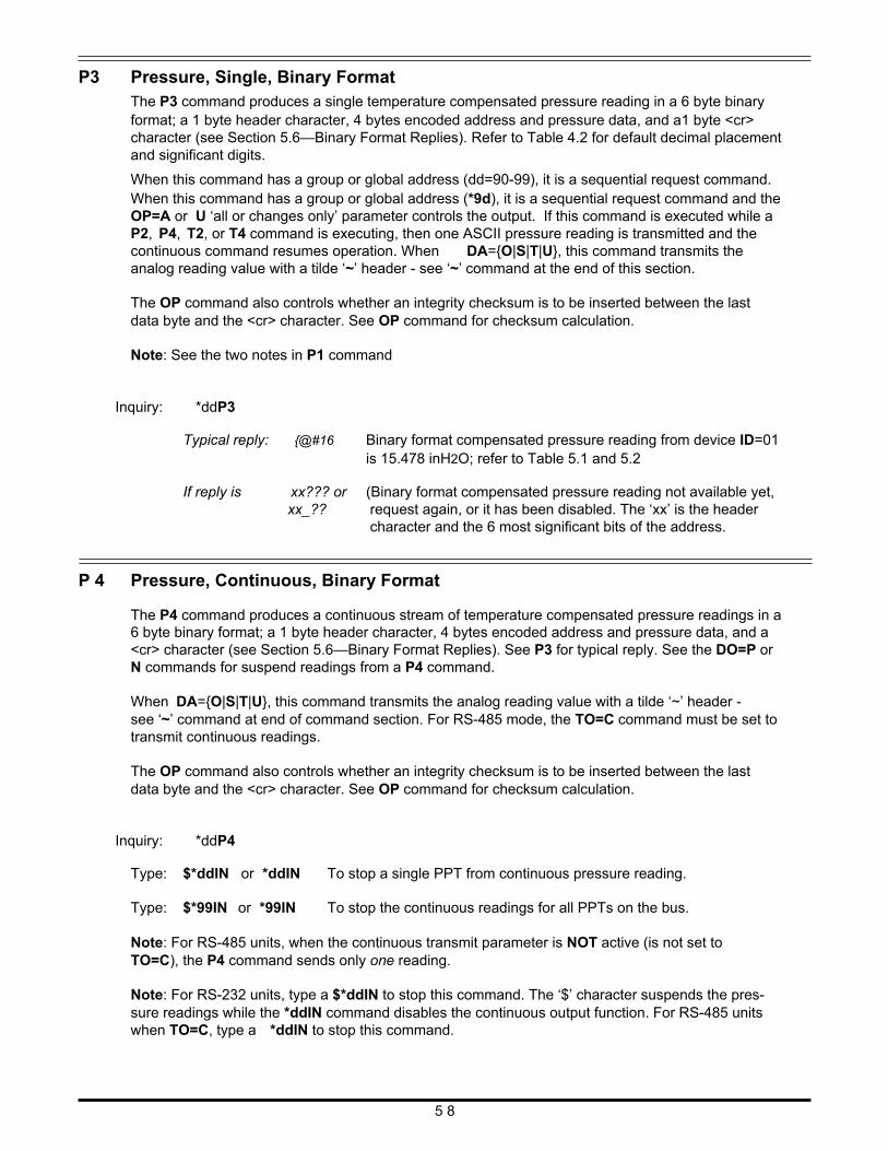
P3
Pressure, Single, Binary Format The P3 command produces a single temperature compensated pressure reading in a 6 byte binary format; a 1 byte header character, 4 bytes encoded address and pressure data, and a1 byte <cr> character (see Section 5.6—Binary Format Replies). Refer to Table 4.2 for default decimal placement and significant digits.
When this command has a group or global address (dd=90-99), it is a sequential request command. When this command has a group or global address (*9d), it is a sequential request command and the OP=A or U ‘all or changes only’ parameter controls the output. If this command is executed while a P2, P4, T2, or T4 command is executing, then one ASCII pressure reading is transmitted and the continuous command resumes operation. When DA={O|S|T|U}, this command transmits the analog reading value with a tilde ‘~’ header - see ‘~’ command at the end of this section.
The OP command also controls whether an integrity checksum is to be inserted between the last data byte and the <cr> character. See OP command for checksum calculation.
Note: See the two notes in P1 command
Inquiry: *ddP3 Typical reply: {@#16 Binary format compensated pressure reading from device ID=01
is 15.478 inH2O; refer to Table 5.1 and 5.2 If reply is xx??? or (Binary format compensated pressure reading not available yet,
xx_?? request again, or it has been disabled. The ‘xx’ is the header character and the 6 most significant bits of the address.
P 4 Pressure, Continuous, Binary Format The P4 command produces a continuous stream of temperature compensated pressure readings in a 6 byte binary format; a 1 byte header character, 4 bytes encoded address and pressure data, and a <cr> character (see Section 5.6—Binary Format Replies). See P3 for typical reply. See the DO=P or N commands for suspend readings from a P4 command.
When DA={O|S|T|U}, this command transmits the analog reading value with a tilde ‘~’ header - see ‘~’ command at end of command section. For RS-485 mode, the TO=C command must be set to transmit continuous readings.
The OP command also controls whether an integrity checksum is to be inserted between the last data byte and the <cr> character. See OP command for checksum calculation.
Inquiry: *ddP4 Type: $*ddIN or *ddIN To stop a single PPT from continuous pressure reading.
Type: $*99IN or *99IN To stop the continuous readings for all PPTs on the bus.
Note: For RS-485 units, when the continuous transmit parameter is NOT active (is not set to TO=C), the P4 command sends only one reading.
Note: For RS-232 units, type a $*ddIN to stop this command. The ‘$’ character suspends the pres- sure readings while the *ddIN command disables the continuous output function. For RS-485 units when TO=C, type a *ddIN to stop this command.
5 8
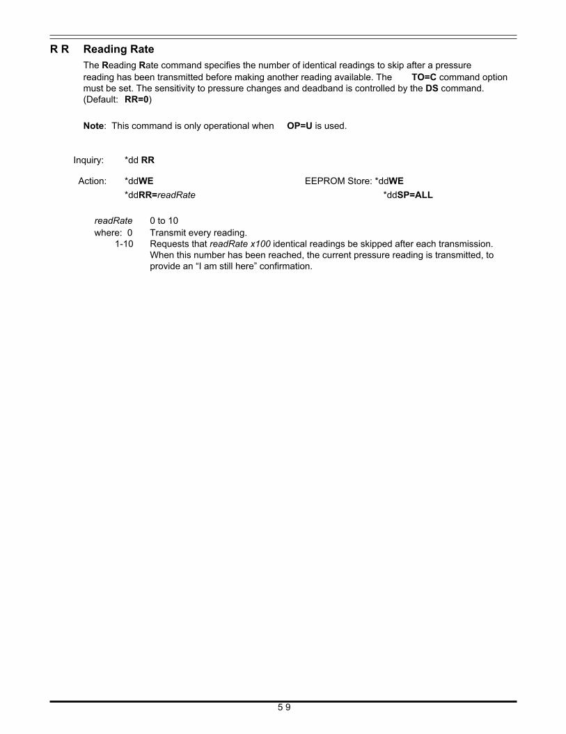
R R Reading Rate The Reading Rate command specifies the number of identical readings to skip after a pressure reading has been transmitted before making another reading available. The TO=C command option must be set. The sensitivity to pressure changes and deadband is controlled by the DS command. (Default: RR=0)
Note: This command is only operational when OP=U is used.
Inquiry: *dd RR Action: *ddWE
*ddRR=readRate
readRate 0 to 10 where: 0 Transmit every reading.
EEPROM Store: *ddWE
*ddSP=ALL
1-10 Requests that readRate x100 identical readings be skipped after each transmission. When this number has been reached, the current pressure reading is transmitted, to provide an “I am still here” confirmation.
5 9
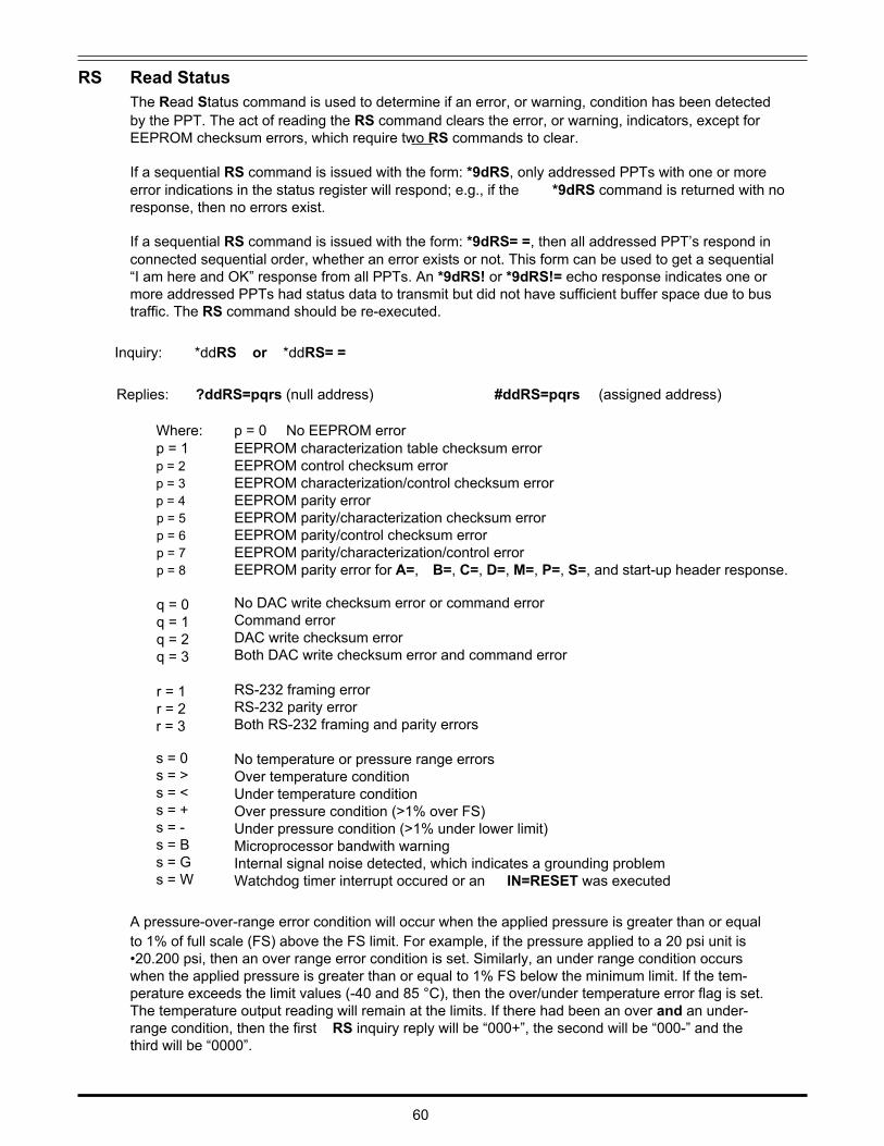
RS Read Status The Read Status command is used to determine if an error, or warning, condition has been detected by the PPT. The act of reading the RS command clears the error, or warning, indicators, except for EEPROM checksum errors, which require two RS commands to clear.
If a sequential RS command is issued with the form: *9dRS, only addressed PPTs with one or more error indications in the status register will respond; e.g., if the *9dRS command is returned with no response, then no errors exist.
If a sequential RS command is issued with the form: *9dRS= =, then all addressed PPT’s respond in connected sequential order, whether an error exists or not. This form can be used to get a sequential “I am here and OK” response from all PPTs. An *9dRS! or *9dRS!= echo response indicates one or more addressed PPTs had status data to transmit but did not have sufficient buffer space due to bus traffic. The RS command should be re-executed.
Inquiry: *ddRS or *ddRS= =
Replies: ?ddRS=pqrs (null address)
Where: p = 0 No EEPROM error
#ddRS=pqrs (assigned address)
p = 1 p = 2 p = 3 p = 4 p = 5 p = 6 p = 7 p = 8 q = 0 q = 1 q = 2 q = 3 r = 1 r = 2 r = 3 s = 0 s = > s = < s = + s = - s = B s = G s = W
EEPROM characterization table checksum error EEPROM control checksum error EEPROM characterization/control checksum error EEPROM parity error EEPROM parity/characterization checksum error EEPROM parity/control checksum error EEPROM parity/characterization/control error EEPROM parity error for A=, B=, C=, D=, M=, P=, S=, and start-up header response. No DAC write checksum error or command error Command error DAC write checksum error Both DAC write checksum error and command error RS-232 framing error RS-232 parity error Both RS-232 framing and parity errors No temperature or pressure range errors Over temperature condition Under temperature condition Over pressure condition (>1% over FS) Under pressure condition (>1% under lower limit) Microprocessor bandwith warning Internal signal noise detected, which indicates a grounding problem Watchdog timer interrupt occured or an IN=RESET was executed
A pressure-over-range error condition will occur when the applied pressure is greater than or equal to 1% of full scale (FS) above the FS limit. For example, if the pressure applied to a 20 psi unit is •20.200 psi, then an over range error condition is set. Similarly, an under range condition occurs when the applied pressure is greater than or equal to 1% FS below the minimum limit. If the tem- perature exceeds the limit values (-40 and 85 °C), then the over/under temperature error flag is set. The temperature output reading will remain at the limits. If there had been an over and an under- range condition, then the first RS inquiry reply will be “000+”, the second will be “000-” and the third will be “0000”. 60
The maximum pressure reading is 105 percent of FS. This limit varies slightly from device to device but will continue to display the out-of-range indicator (“!” in place of “=“) until the pressure drops below 101 percent of FS.
Note: In the unlikely event of EEPROM checksum errors, the temperature and pressure integra- tion cycles stop. This can be overridden by executing two RS commands consecutively, which clears the error indications. Pressure, temperature and DAC readings can then be taken; however, the readings may not be correct. Also the fourth error indicator is prioritized in the order shown. When the RS command is issued with a group or global address (sequential mode), only PPTs which have at least one error condition will respond. Replies are in sequential RS-232 bus loop connection order, followed by the return of the RS command.
Out-of-range temperature has display precedence over out-of-range pressure, which in turn has precedence over microprocessor bandwith warning, which is followed in precedence by noisy signal ground warning. The indication is cleared only if the condition no longer exists. If temperature out- of-range, pressure out-of-range, and microprocessor bandwidth warning all existed, then with successive RS commands, the first command would show the temperature condition, the second command would show the pressure condition, the third command would show the bandwidth warning, and the fourth command would show no error.
61
S= Serial Number The Serial number command reads the factory set PPT serial number. If the response has an ‘!’ character instead of ‘=‘, there was an EEPROM parity error.
Inquiry: *ddS=
RS-485 type only In multidrop bus configuration only this command must be used to identify a PPT for address assignment. Command *99S=ssssssss, where ssssssss is the 8 character serial number of the PPT (in this case the leading zeros of the serial number must be used because the identification match is made on all 8 ASCII characters—not the decimal value of the serial number), identifies the PPT for identification address assignment. The address assignment is then performed by a *99IDnn com- mand, where nn is the address.
Note: If two PPT units on a RS-485 bus have the same ID then you can use the sequence below to re-assign ID numbers
Action: *99WE
*99S=ssssssss (this allows the PPT to accept the next *99ID command)
*99WE
*99ID=nn (this assigns the PPT #ssssssss the ID number ‘nn’) Where: ssssssss is the PPT serial number with sufficient leading zeros to provide 8 characters.
62
S2
S5
S I
Speed Shift x2
The Speed shift x2 command specifies the threshold at which the pressure integration speed doubles; e.g., the integration time is halved. When the pressure change rate falls below the threshold, the PPT resumes transmission at its configured output rate. This command is only operational when the I=Mn form of the Integration command is used. See Figure 4.15 for command illustration. (Default: S2=0)
Inquiry: *ddS2 Action: *ddWE EEPROM Store: *ddWE
*ddS2=thresholdS2 *ddSP=ALL
thresholdS2 0 to 15 where: 0 Disable the x2 speed shift function.
1-15 Sets the speed shift threshold for double speed at thresholdS2x 0.01% FS reading times (threshold = 0.01%FS x thresholdS2).
Speed Shift at 50msec Intervals The Speed shift S5 command specifies the threshold at which the pressure integration speed changes
to outputting every 50 milliseconds. When the pressure change rate falls below the threshold, the PPT resumes transmission at its configured output rate. The 50 msec interval is synchronous with the configured output rate. This command is only operational when the I=Mn form of the Integration command is used. See Figure 4.16 for command illustration. (Default: S5=0)
Inquiry: *ddS5 Action: *ddWE EEPROM Store: *ddWE
*ddS5=thresholdS5 *ddSP=ALL
thresholdS5 0 to 15 where: 0 Disable the S5 speed shift function.
1-15 Sets the speed shift threshold for 50 msec intervals at thresholdS5 x 0.01% FS reading times (threshold = 0.01%FS x thresholdS5).
Synchronize Integration Cycles
RS-485 type only The Synchronize Integration command is used to control the start of a PPT’s pressure integration cycle. When used with group or global addressing on an RS-485 bus, this command simultaneously starts the pressure integration cycles of all addressed PPTs on the bus. The results of pressure integration cycles completed prior to the execution of this command are either preserved for reading or discarded, depending on the operational configuration specified by the TO=C, A, S, or H com- mand. The new integration cycle (I=) begins immediately following the carriage return (<cr>) entry of the SI command. See Figure 4.19 for command illustration.
Action: *ddSI
Setting: When an SI command is sent: TO=C, or A Restart I= cycle TO=S Restart I= cycle, Clear previous I= value T O = H Restart I= cycle, Clear previous I= value, Stop after 1 I= cycle
6 3
SP Store Parameters in EEPROM The Store Parameters command causes all control parameter(s) to be stored in the EEPROM so they are available when power is applied. Only changes are updated, and if an update is made, the control parameter EEPROM checksum is automatically recalculated.
Note: This command will not work when a *ddWE=RAM continuous write enable is active. It must have a singular write enable (*ddWE) command preceding it.
Action: *ddWE
*ddSP= All Writes all parameters to EEPROM.
T = Set Tare Value (gauge units only) The Tare command allows the user to input a tare (zero offset) value, and is applicable only to gauge PPT types. This command has two forms. 1) Use the currently applied pressure to zero the PPT (SET), or 2) The user may supply a zero set point value (TareValue) in terms of a %FS pressure range. If there is an input value limit error, the command error flag in the RS command will be set and no change will occur. A pressure over or under range error will be set (see RS) and the “!” will appear in the reading if the applied pressure exceeds the FS range, or falls below zero, by 1%FS. (Default:T=0.0000)
What is a tare? Setting the tare is similar to setting an offset pressure. An example would be going to the delicatessen and weighing the empty container before filling it. A tare is set to offset the weight of the container so that it is not included in the final weight.
Note: Tare does not affect the analog outputs—see Figure 4.2.
Inquiry: *ddT= Action: *ddWE
*ddT={SET|TareValue}
EEPROM Store: *ddWE
*dd SP=ALL S E T Set tare value to current pressure present at the PPT pressure port.
TareValue -2 to 102 (%FS) TareValue must be a decimal number between 1.02 and -0.02. This corresponds to a tare value that is between 2% above FS and 2% below zero. Up to four digits may be supplied following the decimal point. For example, to tare a 100 psig PPT to 1/1000 psi (=0.01%) below its untared zero point, the command *ddT=-0.01 or *ddT=-.01 would be used. It is advisable to confirm the setting by executing a *ddT= command after the setting is established. The confirmation reply is always in terms of a per- centage of full range (10%FS = 0.1000). If an attempt is made to establish a tare value outside of the allowed range, the tare update will not occur and a command error (see RS) will occur. When the T= command is legally executed, it turns the tare control to ON. See the TC command for subsequent disabling and enabling of the user supplied tare.
6 4
T1
Temperature, Single, °C The T1 command requests a single temperature reading in degrees Celsius. The reading resolution is 0.1 degrees C. When this command has a group or global address, it is a sequential request command. (Factory default is °C, after that, the default will be the last reading type, °C or °F, which is stored in EEPROM during a SP=ALL command.)
A response of #01CT=.. indicates that no temperature reading is available or the last reading was in Fahrenheit. If the last reading was in Fahrenheit, then it will take two inquiries to get the first reading. Successive readings in Celsius only take one inquiry.
A group or global address command echo of *9dT1! indicates that RS-232 buffer space was not available for one or more of the addressed PPTs.
Note: The PPT continuously integrates and calculates pressure and temperature readings. When this command is received, the latest available reading is transmitted if there is sufficient output buffer space.
Inquiry: *ddT1
T 2 Temperature, Continuous, °C The T2 command requests continuous temperature readings in degrees Celsius. Reading rate is controlled by the IC command setting. The reading resolution is 0.1 degrees C. (Default - see T1 command)
Inquiry: *ddT2
Type: $*99IN
To stop the continuous temperature reading command.
Note: For RS-485 units, when the continuous transmit parameter is NOT active (is not set to TO=C), the T2 command sends only one reading.
Note: For RS-232 units, type a $*99IN to stop this command. The ‘$’ character suspends the tem- perature readings while the *99IN command disables the continuous output.
T 3 Temperature, Single, °F The T3 command requests a single temperature reading in degrees Fahrenheit. The reading resolu- tion is 0.1 degrees F. (Factory default is °C, after that, the default will be the last reading type, °C or °F, which is stored in EEPROM during a SP=ALL command.)
A response of #01FT=.. indicates that no temperature reading is available or the last reading was in Celsius. If the last reading was in Celsius, then it will take two inquiries to get the first reading. Successive readings in Fahrenheit will only take one inquiry.
A group or global address command echo of *9dT1! indicates that RS-232 buffer space was not available for one or more of the addressed PPTs.
Note: The PPT continuously integrates and calculates pressure and temperature readings. When this command is received, the latest available reading is transmitted if there is sufficient output buffer space.
Inquiry: *ddT3
6 5
T 4 Temperature, Continuous, °F The T4 command requests continuous temperature readings in degrees Fahrenheit. RS-232 reading rate is controlled by the IC command setting. The reading resolution is 0.1 degrees F. (Default - see T1 command)
Inquiry: *ddT4
Type: $*ddIN or *ddIN To stop a single PPT from continuous temperature reading.
Type: $*99IN or *99IN Stops the continuous pressure reading for all PPTs on the bus. Note: For RS-485 units, when the continuous transmit parameter is NOT active (is not set to TO=C), the T4 command sends only one reading.
Note: For RS-232 units, type a $*99IN to stop this command. The ‘$’ character suspends the tem- perature readings while the *99IN command disables the continuous output.
T C Tare Control Switch
The Tare Control command turns on or off the user controlled tare (zero offset) function. When ON, the setting established by the T= command is used to set the zero reading of the PPT. When OFF, the factory supplied zero setting is used. (Default: TC=OFF)
Inquiry: *dd TC
Action: *ddWE
*dd TC={ ON|OFF}
EEPROM Store: *ddWE
*ddSP=ALL O N Tare control set to T= command value
O F F Tare control set to factory zero setting 6 6
T O Transceiver Operating Parameters Sets the Transceiver Operating parameters for the RS-232, or RS-485, transceiver interface proto- col. The TO=R or M commands can select either a ring or multidrop configuration for RS-232 type PPTs, or a multidrop configuration only for RS-485 type PPTs. All other command parameters apply only to the multidrop RS-485 configuration. See Figure 4.19 for TO=A, S, and H command illustra- tions.
(Default: TO=R0CN for RS-232 type or TO=M1CN for RS-485 type)
Inquiry: *ddTO Action: *ddWE
*ddTO={R|M} or *ddTO={0-3} or
*ddTO= {C|A|S|H} or *dd TO={N|P}
EEPROM Store: *ddWE
*ddSP=ALL
R Ring protocol for RS-232 units. This parameter option cannot be selected for the RS- 485 type.
M Multidrop protocol for RS-485 units. This option can be selected for RS-232 unit, but
requires an external RS-232 to RS-485 converter. If an RS-232 unit has TO=M selected, then all the options labeled “RS-485 only” apply.
..............................................................................................................................
0-3 Controls the minimum command response delay, RS-485 bus turn around time. For baud rate of 9600 and below, each count (0-3) represents about 1 millisecond. For baud rates above 9600, each count represents one character transmission time. This feature has no effect on RS-232 units.
Baud
1200 2400 4800 9600 14400 19200 28800 time/count 1 ms 1 ms 1 ms 1 ms 0.7 ms 0.5 ms 0.3 ms
..............................................................................................................................
C Allows a RS-485 unit to transmit Continuous pressure readings (P2 or P4) when the device ID is used. This parameter has no effect on RS-232 units.
A RS-485 only: Causes the SI command to start a pressure integration cycle and not clear the result of the previous cycle so it can be read with a P2 or P4 command if the result has not been previously read. When the synchronized cycle completes a new cycle is immediately started.
S RS-485 only: Causes the SI command to start a pressure integration cycle and clear the result of the previous cycle so that a P2 or P4 command produces a “pressure reading not available” indication (<cr> only) if a P2 or P4 read attempt is made before the new integration cycle completes. When the synchronized cycle completes, a new cycle is immediately started. If the pressure reading produced by the synchro- nized cycle is to be read it must be read before the next integration cycle completes
H RS-485 only: Causes the SI command to start a pressure integration cycle and clear
the result of the previous cycle so that a P2 or P4 command produces a “pressure reading not available indication” (<cr> only) if a P2 or P4 read attempt is made before the new integration cycle completes. When the synchronized cycle completes, the pressure reading is Held until it is read or until a new SI command is issued.
Setting:
When an SI command is sent: TO=C, or A Restart I= cycle TO=S T O = H
Restart I= cycle, Clear previous I= value Restart I= cycle, Clear previous I= value, Stop after 1 I= cycle
6 7
..............................................................................................................................
N Normal read operation response. This parameter has no effect on RS-232 units. In RS- 485 mode, each PPT will respond to a group or global read operation after the unit with the next lower device ID (for global) or next lower sub-address (for group) has re- sponded. Device ID, and group sub-addresses, must be sequential beginning with number 01.
P RS-485 only: Prompted read operation response. In RS-485 mode, after the lower addressed PPT responds to a group or global read operation, this PPT will not re- spond until it is prompted by a <cr> from the bus system host. The <cr> may also be manually entered by the user to get each successive response. To receive data from each prompt, the device ID, or group sub-addresses, must be sequential beginning with number 01.
Note: If an RS-485 unit receives a group or global addressed (*9x) command and fails to respond, the command terminates at that point until additional carriage returns are received. Usually, the reason for failure to respond is that the device IDs or group sub- addresses were not sequential beginning with number 01.
U = User Supplied Display Units
The User supplied display units command allows the user to enter units of measure for the PPT. The value entered for this command is multiplied by the actual pressure in psi to get the user defined units. For example, if *ddU=15.0<cr>, then the compensated pressure output values will be 15 times the actual psi value. This function (multiplier) is activated by executing the *ddDU=USER<cr> command. If there is an input error, then the command error flag in the RS command will be set and no change will occur.
Inquiry: *ddU=
Action: *ddWE
*ddU=UserValue
EEPROM Store: *ddWE
*ddSP=ALL UserValue Must be a value between 0.0010000 and 999.99. It is advisable to confirm the setting
by executing a *ddU=<cr> command after the U= setting is established. The user supplied display function is activated by executing the *ddDU=USER<cr> com- mand.
V = Version Number
This Version number command transmits the factory set software version number. Inquiry: *ddV=
Reply: #01V=02.4C4S2V
02.4C4 Software version number S or R PPT Type
2 or 4 Digital Output
V Analog Output
6 8
S: PPT
2: RS-232
V: 0-5 volt
R: PPT-R
4: RS-485
W= Width of Pressure Window Set the width, or span, of the pressure window to a smaller range to fill the analog output voltage limits. This command sets a pressure window value, or span, from 0 to 99% of full scale. An W= inquiry reads the value in percent of full scale (F= value). This command is used with the O=, L=, and H= commands to customize the size of the PPT analog pressure window and analog output voltage. If there is an input error, then the command error flag in the RS command will be set and no change will occur. This com- mand is enabled by the AN command. See Figure 4.5 for command illustration. (Default: W=100)
For example when L=0 and H=0, if a 20 psia, psig, or psid unit has the pressure window width set to W=60, then the 0 to 5 volt analog output span would correspond to 0 to 12 psi (60% of 20 psi). Use the O= command (O=20) to offset the pressure window by 4 psi. Now the analog output values range from 0 volt=4 psi up to 5 volt=16 psi.
If a 20 psid unit has the pressure window width set to W=60, then the pressure window would be 24 psi (60% of 40 psi). The analog 0V output would begin at -20 psi, cross 2.5V at -8 psi, and output 5V at 4 psi. If a window offset of O=20 was set, then the analog 0V output would begin at -12 psi, cross 2.5V at 0 psi, and output 5V at 12 psi. If an O= value is set > 40, then it is automatically set to 40.
Note: Setting a pressure window (W=) value that causes the maximum output pressure to exceed 5V will automatically scale to window offset (O=) value to maintain the 5V limit.
Inquiry: *ddW= Action: *ddWE
*ddW=pp |S
EEPROM Store: *ddWE
*ddSP=ALL pp 0 - 100 (%) This number is a percent multiplier (%) of the full scale pressure that sets the
pressure span across the analog output range. It can also be thought of as scaling, or shrinking, the pressure window to fill the output voltage range. A W=0 setting will set the pressure window is 100%, full span. A W= entry greater than 100 will set W=100.
..............................................................................................................................
S This enables the analog output setpoint. The setpoint trip voltage is controlled by the O= command. The setpoint null, or hysteresis, is controlled by the DS command. The setpoint off voltage is controlled by the L= command and the on voltage is controlled by the H= command. See Figure 4.8 for command illustration.
6 9
W E Write Enable to EEPROM or RAM
The Write Enable command enables an EEPROM write or a RAM write operation. It is used as a safeguard to prevent erroneous command sequences from changing the PPT configuration. A *ddWE command must immediately precede the SP, A=, B=, C= or D= commands when storing information in the EEPROM. The *ddWE command must also immediately precede any command that changes the configuration parameters in the RAM. When manually making multiple configuration changes, *ddWE=RAM command form may be used to permanently enable RAM updates until the next *ddWE or *ddWE=OFF command is executed.
Note: The *ddWE command remains active until the next ‘*’ followed by a <cr> is received, or a ‘*9..<cr>’ passes through from a group or global addressed command.
Action: *ddWE
This enables the next command to write to the RAM or EEPROM, and also disables the *ddWE=RAM condition after the next command is received.
Action: *ddWE=RAM
This provides a permanent RAM write enable. All commands following a *ddWE=RAM will be stored in RAM. A *ddWE command will disabled, or deactivate, this permanent RAM write enable. The *ddWE=RAM command will not allow the SP command to write to EEPROM.
Action: *ddWE=OFF
This immediately disables the *ddWE=RAM condition.
X= Slope 1—User Compensation Control The user can adjust the pressure vs. output curve using the X=, Y=, and Z= commands. The X= command adjusts the slope of the pressure output curve for positive pressures. This applies to all absolute and gauge devices and modifies the positive full scale slope of compound PPTs. The range of adjustment is ±0.6%FS in 0.005% increments. Use the modified full scale value if the F= command is set. For differential units, use one-half the range (FS=10 for a 10psid). If there is an input error, then the command error flag in the RS command will be set and no change will occur. See Figure 4.6 for command illustration. (Default: X=0)
Inquiry: *ddX= Action: *ddWE
*ddX=pp
EEPROM Store: *ddWE
*dd SP=ALL pp 0 to ±120 This number adjusts the pressure reading by multiplying it by 0.005% and
scaling the slope of the pressure reading before output. Pressure Output = [1 + (pp x 0.00005)] x Pressure Reading
70
Y= Slope 2—User Compensation Control The user can adjust the pressure vs. output curve using the X=, Y=, and Z= commands. The Y= command adjusts the slope of the pressure output curve for negative pressures. This modifies the negative full scale slope. The range of adjustment is ±0.6%FS in 0.005% increments. Use the modi- fied full scale value if the F= command is set. For differential units use one-half the range (FS=10 for a 10psid). If there is an input error, then the command error flag in the RS command will be set and no change will occur. See Figure 4.6 for command illustration. (Default: Y=0)
Inquiry: *ddY= Action: *ddWE
*ddY=pp pp 0 to ±120 (see X= for definition)
Z= Offset—User Compensation Control
EEPROM Store: *ddWE
*ddSP=ALL
The user can adjust the pressure vs. output curve using the X=, Y=, and Z= commands. The Z= command adjusts the offset of the pressure output curve. This applies to all PPTs. The range of adjustment is ±0.6%FS in 0.005% increments. For differential units use one-half the range (FS=10 for a 10psid). Use the customized full scale value (F=) as a multiplier.
For gauge type units, a zero offset null may be set by removing pressure and executing a Z=CAL command. For a differential unit, a zero offset null can be set by applying equal pressure to both ports and execute a Z=CAL command.
For PPTR’s, the Z= command should be used to account for mounting orientation. The PPTR’s have an oil filled stainless steel diaphragm that protects the sensor from corrosive media. This oil fill will cause an offset in pressure reading when the PPTR is mounted in any position other than horizontal. A method of calibration for the PPTR is described below for various mounting orientations.
If there is an input error, then the command error flag in the RS command will be set and no change will occur. See Figure 4.7 for command illustration. (Default: Z=0)
Inquiry: *ddZ= Action: *ddWE
* d dZ = { p p| C A L|R E F |S E T }
EEPROM Store: *ddWE
*ddSP=ALL pp 0 to ±120 This number adjusts the pressure reading by adding (pp x 0.005% FS) to the
reading before outputting.
Pressure Output = [(pp x 0.00005) x (M= full scale)] + Pressure Reading C A L Sets the zero pressure condition to zero output. Offset is calculated and stored, then
applied to all readings thereafter. Set Z=0 to cancel. The range of correction for the CAL command is the same as pp described above. If the correction is out of range, then the the Z= parameter will be set to a maximum value (+120 or -120).
Note: When the Z=CAL command is executed and there is a deadband (DS) set, the output may not read zero when it actually is. To read zero pressure, turn the deadband off (DS=0).
7 1
PPTR units only
R E F For absolute type PPTR only. The physical orientation of the PPTR can cause the pressure reading to be offset from its factory calibrated value, particularly for low pressure range units. The REF and SET commands can be used to remove this offset. PPTRs are calibrated with the pressure port oriented down and if the unit is mounted in the applica- tion with the pressure port down, then no offset correction is required. However, if the PPTR is to be mounted in an orientation other than pressure port down, then the offset can be corrected as follows: 1) Orient the PPTR with the pressure port down. 2) Vent the pressure port to atmosphere. Read and record the value of Z= and the current pressure reading. Execute the following commands: *ddWE
*ddZ=REF S E T 3) To complete the above offset correction sequence, orient the PPT-R in the application
mount orientation. Note if the pressure reading has changed and if so, execute the follow- ing commands; *ddWE *dd Z=SET 4) Read the pressure and note that it has moved back to the original reading value. Per- form an EEPROM store to make the correction permanent.
Note: For gauge type PPTRs, the orientation offset is corrected with the Z=CAL command after the unit has been mounted in its application orientation.
$
Suspend Continuous Readings This is not actually a command but a special command header character. During a continuous pressure reading command, P2 or P4 in RS-232 ring configuration or when the bus noise protection parameter is used (DO command) in multidrop configuration, a ‘$’ by itself will temporarily stop, or suspend, transmission. Pressure readings will continue to be taken at the configured rate but will not be transmitted on the RS-232 outputs. This allows for manual entry of a command when continu- ous readings are filling the display. Pressure reading transmission will resume when the <cr> carriage return (ENTER key) is pressed.
Note: Under some conditions it is possible to enter a command that will not cause continuous readings to resume after entering the <cr> character, in which case a second <cr> will cause the continuous readings to resume.
Example: *dd P2 (Start continuous pressure readings) $*ddV= (Suspend continuous pressure readings to read version number)
(Resume continuous pressure reading after the V= reply)
7 2
~
Command Header for Binary DAC Values
The ‘~’ (tilde) command is actually a command header and is used to apply a binary format value to the DAC input. This allows the host processor or a remote PPT to control the DAC analog output. This command provides up to 40% reduction in analog control message length, compared to the N= command, and allows the use of a cyclic checksum. Before executing this command, the digital/ analog control must be set to DA=G, N, or R and the analog write must be enabled (see the NE command).
The data format consists of six bytes: 1 byte header character (~), 4 bytes data, and 1 byte <cr> character. The 4 byte data value bbbb contains the device address and the analog output value. The most significant bit of each ‘b’ character is a parity bit. The next most significant bit of each ‘b’ character is either a 1 or 0, in order to make the resultant byte a printable character. The 6 least significant bits of each character are used for the device address and analog output value.
The device address and the analog output value can be encoded by first defining the 7 bit binary address and the 17 bit binary analog value and then, separating them into four 6 bit groups. The analog value is expressed in tenths of millivolts so that 2.5V = 25,000. As an example, for device ID=1 and analog value = 4.25 volts (42,500 count), the following binary strings are formed: 0000001 01010011000000100. Grouping this string into four 6 bit groups gives: 000000 101010 011000 000100. Converting these to printable characters using Table 5.2 give the four byte string: @jXD. Therefore, the command ~@jXD<cr> will set the DAC output to 4.2500 volts when DA=G, N, or R and the NE=DAC is enabled.
Note: The PPT transmits ‘~’ command data when DA=O, S, T, or U and a P3 or P4 is activated. The address of the transmitted ‘~’ command is the group address of the PPT.
Note: This mode can be used to run a closed loop system. That is, the host processor can be monitor- ing a line pressure using the digital pressure readings. Then, the host processor can drive an analog signal back to a valve control based on the digital readings.
Action: *ddNE (must precede each ‘~’ command)
~bbbb or ~bbbbs
Action: *ddNE=DAC (only required one time)
~bbbb or ~bbbbs Action: *ddNE=CKS (only required one time)
~bbbbs
bbbb Four ASCII characters whose least significant six bits provide the device address and
analog output value. The first 7 bits represent a binary address (0-99). The last 17 bits contains a binary output value expressed in tenths of millivolts. A zero to five volt range is coded as 0 to 50,000 counts. See binary format, Section 5.6, and Table 5.2 for the list of ASCII characters.
s Cyclic checksum character. When all of the characters in the message, including the header and this character, are added together (without carries), the least significant six bits of the resultant sum will be zero. Do not include the <cr>. See Table 5.2 for the list of characters to be used.
7 3
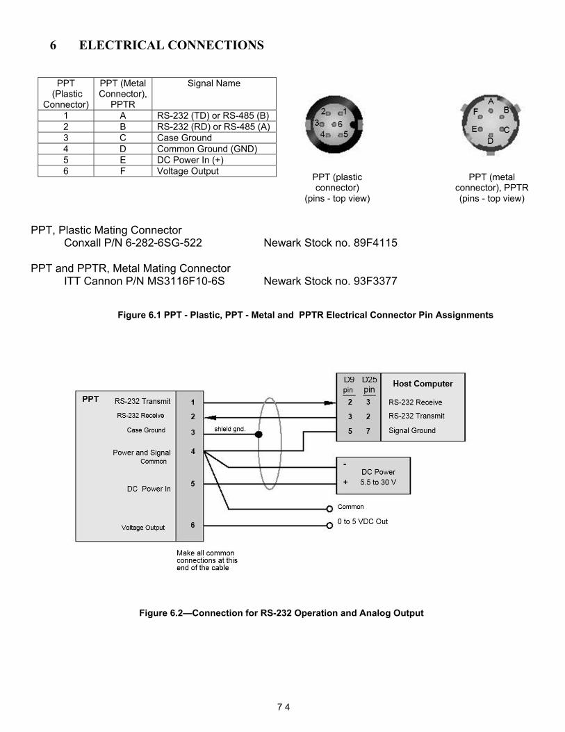
6 ELECTRICAL CONNECTIONS
PPT
(Plastic Connector)
PPT (Metal Connector),
PPTR
Signal Name
1 A RS-232 (TD) or RS-485 (B) 2 B RS-232 (RD) or RS-485 (A) 3 C Case Ground 4 D Common Ground (GND) 5 E DC Power In (+) 6 F Voltage Output
PPT, Plastic Mating Connector
Conxall P/N 6-282-6SG-522 Newark Stock no. 89F4115
PPT and PPTR, Metal Mating Connector ITT Cannon P/N MS3116F10-6S Newark Stock no. 93F3377
Figure 6.1 PPT - Plastic, PPT - Metal and PPTR Electrical Connector Pin Assignments
Figure 6.2—Connection for RS-232 Operation and Analog Output
7 4
PPT (metal connector), PPTR (pins - top view)
PPT (plastic connector)
(pins - top view)
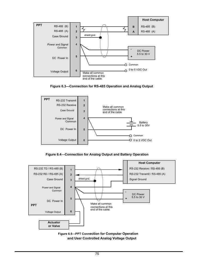
PPT
RS-485 (B)
RS-485 (A)
Case Ground
Power and Signal Common
1
2
3
4
shield gnd.
-
B
A
Host Computer
RS-485 (B)
RS-485 (A)
DC Power 5.5 to 30 V
DC Power In
Voltage Output
5 6
Make all common connections at this end of the cable.
+
Common
0 to 5 VDC Out
PPT
Figure 6.3—Connection for RS-485 Operation and Analog Output RS-232 Transmit 1
RS-232 Receive
Case Ground
Power and Signal Common
DC Power In
Voltage Output
2
3
4
5
6
Make all common connections at this end of the cable
Battery 5.5 to 30V
Common
0 to 5 VDC Out
Figure 6.4—Connection for Analog Output and Battery Operation
Host Computer
RS-232 TD / RS-485 (B)
RS-232 RD / RS-485 (A)
Case Ground
Power and Signal Common
DC Power In
PPT Voltage Output
Actuator or Valve
1
2
3
4
5
6
shield gnd.
Make all common connections at this end of the cable.
- +
RS-232 Receive / RS-485 (B)
RS-232 Transmit / RS-485 (A)
Signal Ground
DC Power 5.5 to 30 V
Figure 6.5—PPT Connection for Computer Operation and User Controlled Analog Voltage Output
75
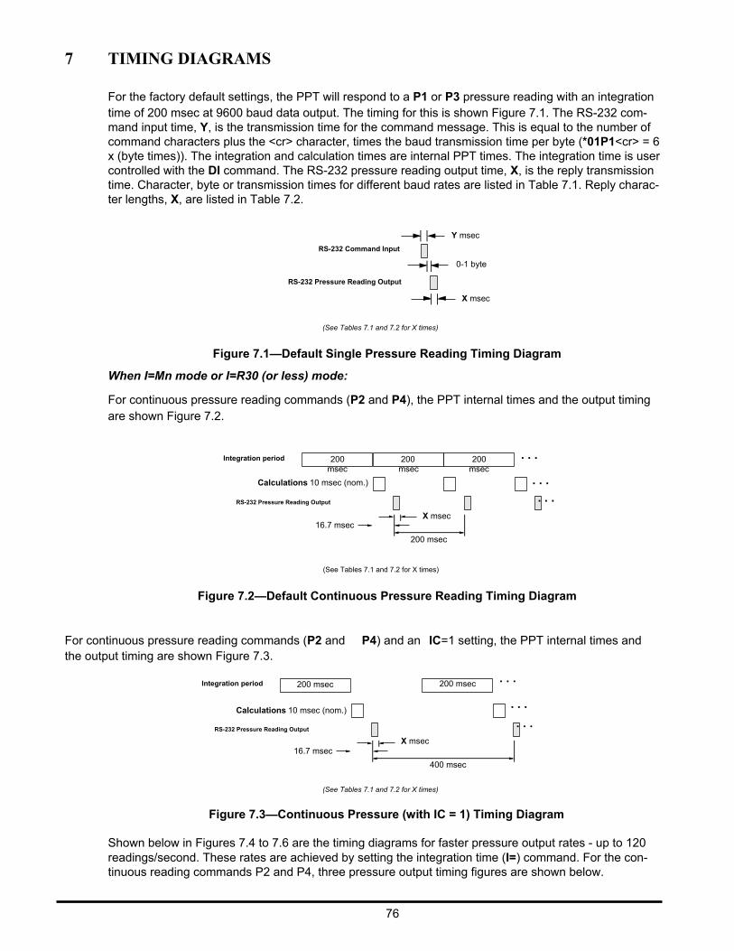
7 TIMING DIAGRAMS
For the factory default settings, the PPT will respond to a P1 or P3 pressure reading with an integration time of 200 msec at 9600 baud data output. The timing for this is shown Figure 7.1. The RS-232 com- mand input time, Y, is the transmission time for the command message. This is equal to the number of command characters plus the <cr> character, times the baud transmission time per byte (*01P1<cr> = 6 x (byte times)). The integration and calculation times are internal PPT times. The integration time is user controlled with the DI command. The RS-232 pressure reading output time, X, is the reply transmission time. Character, byte or transmission times for different baud rates are listed in Table 7.1. Reply charac- ter lengths, X, are listed in Table 7.2.
Y msec
RS-232 Command Input
0-1 byte
RS-232 Pressure Reading Output
X msec
(See Tables 7.1 and 7.2 for X times)
Figure 7.1—Default Single Pressure Reading Timing Diagram
When I=Mn mode or I=R30 (or less) mode:
For continuous pressure reading commands (P2 and P4), the PPT internal times and the output timing are shown Figure 7.2.
Integration period
200 msec
200 msec
200 msec
. . .
Calculations 10 msec (nom.)
RS-232 Pressure Reading Output
16.7 msec
X msec
200 msec
. . .
. . .
(See Tables 7.1 and 7.2 for X times)
Figure 7.2—Default Continuous Pressure Reading Timing Diagram
For continuous pressure reading commands (P2 and P4) and an IC=1 setting, the PPT internal times and the output timing are shown Figure 7.3.
Integration period
200 msec
200 msec . . .
Calculations 10 msec (nom.)
RS-232 Pressure Reading Output
16.7 msec
X msec
400 msec
. . .
. . .
(See Tables 7.1 and 7.2 for X times)
Figure 7.3—Continuous Pressure (with IC = 1) Timing Diagram
Shown below in Figures 7.4 to 7.6 are the timing diagrams for faster pressure output rates - up to 120 readings/second. These rates are achieved by setting the integration time (I=) command. For the con- tinuous reading commands P2 and P4, three pressure output timing figures are shown below.
76
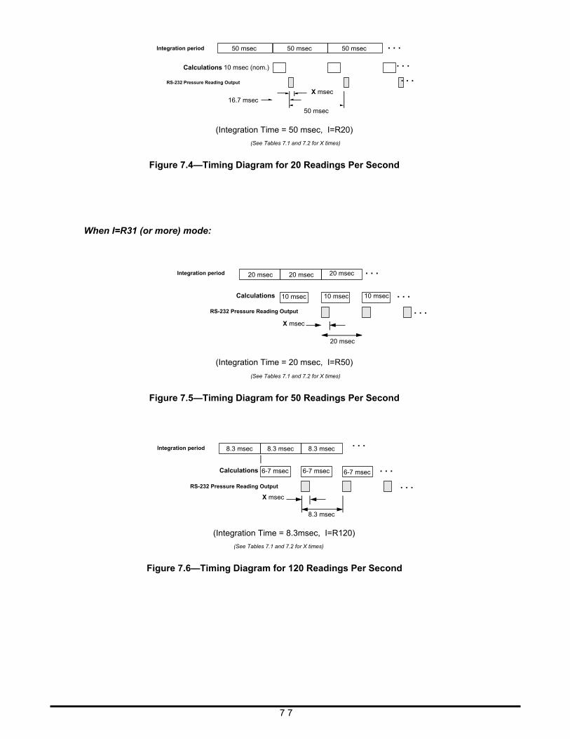
Integration period
50 msec
50 msec
50 msec
. . .
Calculations 10 msec (nom.)
RS-232 Pressure Reading Output
16.7 msec
X msec
50 msec
. . .
. . .
(Integration Time = 50 msec, I=R20)
(See Tables 7.1 and 7.2 for X times)
Figure 7.4—Timing Diagram for 20 Readings Per Second
When I=R31 (or more) mode: Integration period
20 msec
Calculations
20 msec
10 msec
20 msec
10 msec
. . .
10 msec
. . .
RS-232 Pressure Reading Output
X msec
20 msec
. . .
(Integration Time = 20 msec, I=R50)
(See Tables 7.1 and 7.2 for X times)
Figure 7.5—Timing Diagram for 50 Readings Per Second Integration period
8.3 msec
Calculations
8.3 msec
6-7 msec
8.3 msec
6-7 msec
. . . 6-7 msec
. . .
RS-232 Pressure Reading Output
X msec
8.3 msec
. . .
(Integration Time = 8.3msec, I=R120)
(See Tables 7.1 and 7.2 for X times)
Figure 7.6—Timing Diagram for 120 Readings Per Second
7 7
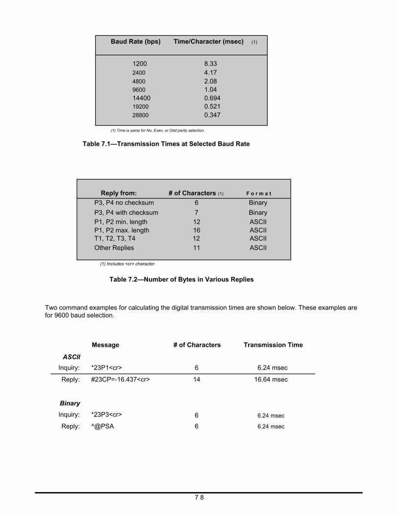
Baud Rate (bps) Time/Character (msec) (1)
1200 2400
4800
9600
14400 19200
28800
8.33 4.17 2.08 1.04 0.694 0.521 0.347
(1) Time is same for No, Even, or Odd parity selection
Table 7.1—Transmission Times at Selected Baud Rate
Reply from:
P3, P4 no checksum
P3, P4 with checksum
P1, P2 min. length P1, P2 max. length T1, T2, T3, T4
Other Replies (1) Includes <cr> character
# of Characters (1)
6
7
12 16 12
11
F o r m a t
Binary
Binary
ASCII ASCII ASCII
ASCII
Table 7.2—Number of Bytes in Various Replies Two command examples for calculating the digital transmission times are shown below. These examples are for 9600 baud selection.
ASCII
Message
# of Characters
Transmission Time
Inquiry: *23P1<cr>
Reply: #23CP=-16.437<cr>
Binary
Inquiry: *23P3<cr>
Reply: ^@PSA
6
14 6
6 7 8
6.24 msec
16.64 msec 6.24 msec
6.24 msec
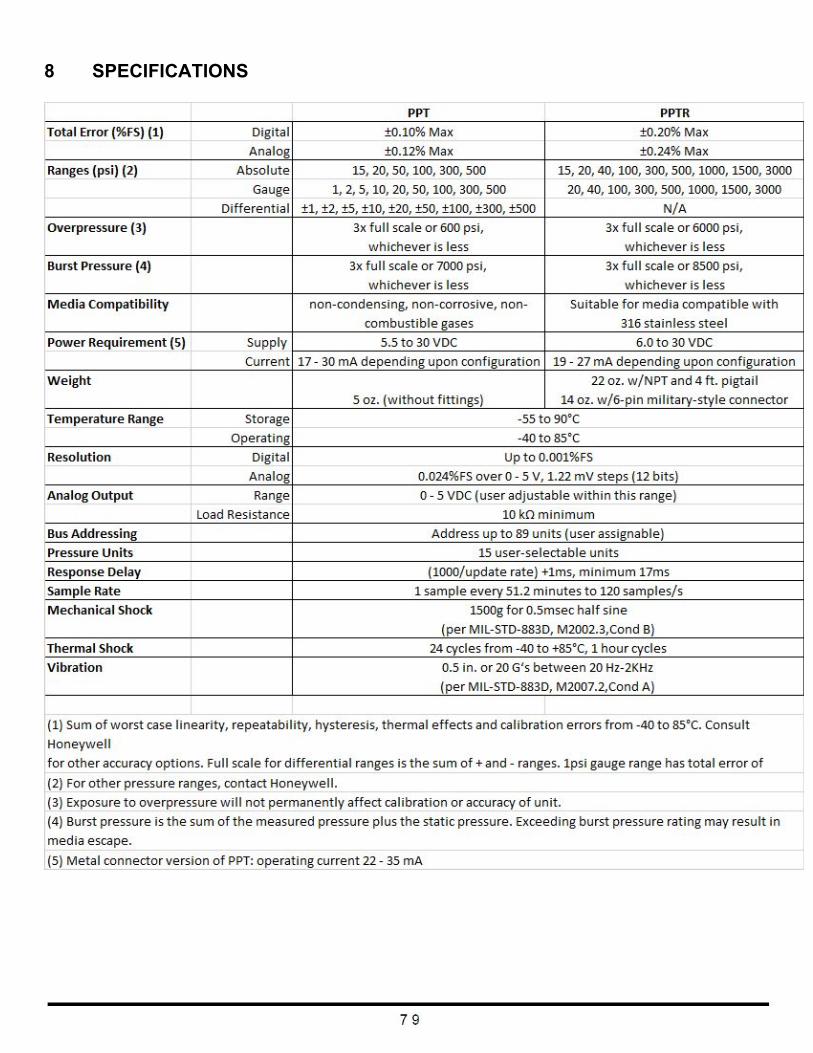
8 SPECIFICATIONS
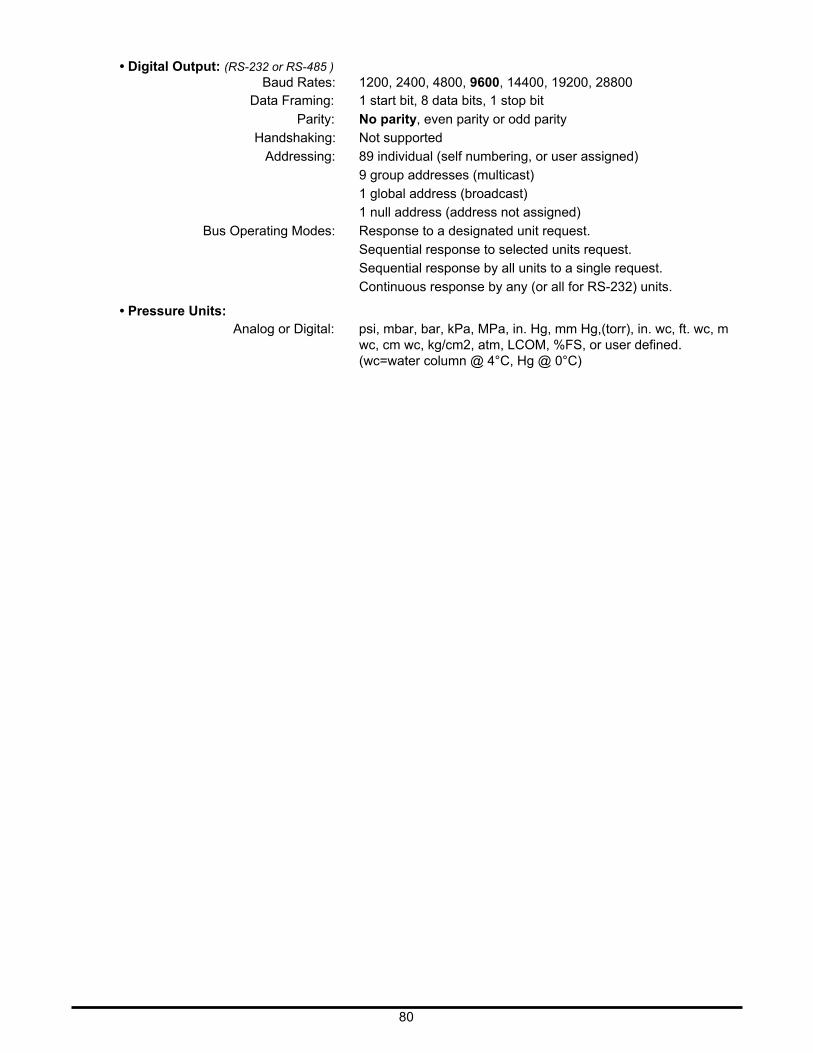
• Digital Output: (RS-232 or RS-485 )
Baud Rates: 1200, 2400, 4800, 9600, 14400, 19200, 28800 Data Framing: 1 start bit, 8 data bits, 1 stop bit
Parity: No parity, even parity or odd parity
Handshaking: Not supported
Addressing: 89 individual (self numbering, or user assigned)
9 group addresses (multicast)
1 global address (broadcast)
1 null address (address not assigned)
Bus Operating Modes: Response to a designated unit request.
Sequential response to selected units request.
Sequential response by all units to a single request.
Continuous response by any (or all for RS-232) units.
• Pressure Units: Analog or Digital: psi, mbar, bar, kPa, MPa, in. Hg, mm Hg,(torr), in. wc, ft. wc, m
wc, cm wc, kg/cm2, atm, LCOM, %FS, or user defined. (wc=water column @ 4°C, Hg @ 0°C)
80
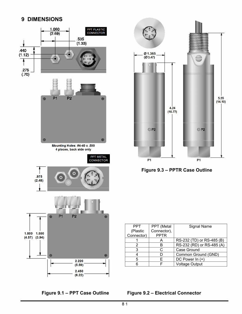
9 DIMENSIONS
Figure 9.3 – PPTR Case Outline
PPT
(Plastic Connector)
PPT (Metal Connector),
PPTR
Signal Name
1 A RS-232 (TD) or RS-485 (B) 2 B RS-232 (RD) or RS-485 (A) 3 C Case Ground 4 D Common Ground (GND) 5 E DC Power In (+) 6 F Voltage Output
Figure 9.1 – PPT Case Outline Figure 9.2 – Electrical Connector
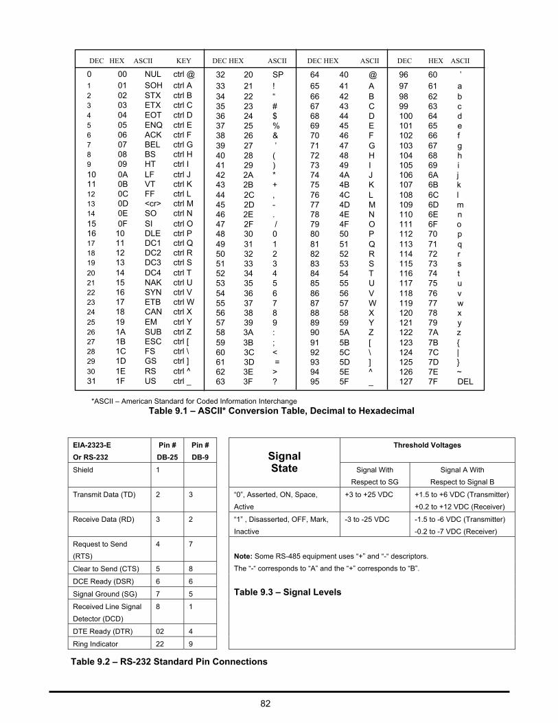
DEC HEX ASCII KEY
DEC HEX ASCII
DEC HEX ASCII DEC HEX ASCII
0 1 2 3
00 NUL ctrl @ 01 SOH ctrl A 02 STX ctrl B 03 ETX ctrl C
32 20 33 21 34 22 35 23
SP ! “ #
64 65 66 67
40 41 42 43
@ A B C
96 97 98 99
60 61 62 63
’ a b c
4 5 6 7 8 9
04 EOT ctrl D 05 ENQ ctrl E 06 ACK ctrl F 07 BEL ctrl G 08 BS ctrl H 09 HT ctrl I
36 24 37 25 38 26 39 27 40 28 41 29
$ % & ’ ( )
68 69 70 71 72 73
44 45 46 47 48 49
D E F G H I
100 64 101 65 102 66 103 67 104 68 105 69
d e f g h i
10 11 12 13 14
0A LF ctrl J 0B VT ctrl K 0C FF ctrl L 0D <cr> ctrl M 0E SO ctrl N
42 2A * 43 2B + 44 2C , 45 2D - 46 2E .
74 75 76 77 78
4A J 4B K 4C L 4D M 4E N
106 6A j 107 6B k 108 6C l 109 6D m 110 6E n
15 0F SI ctrl O 47 2F / 79 4F O 111 6F o 16 17 18 19
20 21 22 23 24
25
10 11 12 13 14 15 16 17 18 19
DLE ctrl P DC1 ctrl Q DC2 ctrl R DC3 ctrl S DC4 ctrl T NAK ctrl U SYN ctrl V ETB ctrl W CAN ctrl X EM ctrl Y
48 30 49 31 50 32 51 33 52 34 53 35 54 36 55 37 56 38 57 39
0 1 2 3 4 5 6 7 8 9
80 81 82 83 84 85 86 87 88 89
50 51 52 53 54 55 56 57 58 59
P Q R S T U V W X Y
112 70 113 71 114 72 115 73 116 74 117 75 118 76 119 77 120 78 121 79
p q r s t u v w x y
26 27 28 29
30
1A SUB ctrl Z 1B ESC ctrl [ 1C FS ctrl \ 1D GS ctrl ] 1E RS ctrl ^
58 3A : 59 3B ; 60 3C < 61 3D = 62 3E >
90 91 92 93 94
5A Z 5B [ 5C \ 5D ] 5E ^
122 7A z 123 7B { 124 7C | 125 7D } 126 7E ~
31 1F US ctrl _ 63 3F ? 95 5F _ 127 7F DEL
Table 9.2 – RS-232 Standard Pin Connections 82
EIA-2323-E
Or RS-232
Pin #
DB-25
Pin #
DB-9
Signal State
Threshold Voltages
Shield 1 Signal With
Respect to SG
Signal A With
Respect to Signal B
Transmit Data (TD) 2 3 “0”, Asserted, ON, Space,
Active
+3 to +25 VDC +1.5 to +6 VDC (Transmitter)
+0.2 to +12 VDC (Receiver)
Receive Data (RD) 3 2 “1” , Disasserted, OFF, Mark,
Inactive
-3 to -25 VDC -1.5 to -6 VDC (Transmitter)
-0.2 to -7 VDC (Receiver)
Request to Send
(RTS)
4 7
Note: Some RS-485 equipment uses “+” and “-“ descriptors.
The “-“ corresponds to “A” and the “+” corresponds to “B”.
Table 9.3 – Signal Levels
Clear to Send (CTS) 5 8
DCE Ready (DSR) 6 6
Signal Ground (SG) 7 5
Received Line Signal
Detector (DCD)
8 1
DTE Ready (DTR) 02 4
Ring Indicator 22 9
*ASCII – American Standard for Coded Information Interchange Table 9.1 – ASCII* Conversion Table, Decimal to Hexadecimal

ADS-14052 Rev B, 10/16 Customer Service Representative Email: quotes.honeywell.com Web: www.pressuresensing.com
No part of this manual may be reproduced or transmitted in any form or by any means, electronic or mechanical, including photocopying and recording, for any purpose, without the express written permission of Honeywell, Inc. Honeywell reserves the right to make changes to any products or technology herein to improve reliability, function or design. Honeywell does not assume any liability arising out of the application or use of any product or circuit described herein; neither does it convey any license under its patent rights nor the rights of others.

Honeywell Aerospace 12001 State Highway 55 Plymouth, MN 55441 www.honeywell.com