PPS 04 - EP 01 00 00 02 SP - 11kV AC Indoor Switchgear ... · unit, physically separated ... This...
42
Discipline Engineering Standard - NSW Category Electrical Title 11 kV AC Indoor Switchgear – Non-Withdrawable Reference Number PPS 04 - (RIC Standard: EP 01 00 00 02 SP) Document Control Status Date Prepared Reviewed Endorsed Approved Standards and Systems Signalling Standards Engineer GM Infrastructure Strategy & Performance Safety Committee Issue 1 Revision 2 Mar 05 Refer to Reference Number T Moore M Owens Refer to minutes of meeting 24/01/05
Transcript of PPS 04 - EP 01 00 00 02 SP - 11kV AC Indoor Switchgear ... · unit, physically separated ... This...

DisciplineEngineering Standard - NSW
CategoryElectrical
Title
11 kV AC Indoor Switchgear –Non-Withdrawable
Reference Number
PPS 04 - (RIC Standard: EP 01 00 00 02 SP)
Document Control
Status Date Prepared Reviewed Endorsed Approved
Standards andSystems
SignallingStandardsEngineer
GMInfrastructure
Strategy &Performance
SafetyCommittee
Issue 1Revision 2 Mar 05
Refer toReferenceNumber
T Moore M OwensRefer to minutes
of meeting24/01/05

Engineering Standard–NSWElectrical PPS 0411 kV AC Indoor Switchgear - Non-Withdrawable
Issue 1 © Australian Rail Track CorporationRevision 2 This document is uncontrolled when printedMarch 2005 Page 2 of 42
Disclaimer
Australian Rail Track Corporation has used its best endeavors to ensure that the content,layout and text of this document is accurate, complete and suitable for its stated purpose.It makes no warranties, express or implied, that compliance with the contents of thisdocument shall be sufficient to ensure safe systems of work or operation. Australian RailTrack Corporation will not be liable to pay compensation in respect of the content orsubsequent use of this document for any other purpose than its stated purpose or for anypurpose other than that for which it was prepared except where it can be shown to haveacted in bad faith or there has been willful default.
Document Approval
The technical content of this document has been approved by the relevant ARTCengineering authority and has also been endorsed by the ARTC Safety Committee.
Document Supply and Control
The Primary Version of this document is the electronic version that is available andaccessible on the Australian Rail Track Corporation Internet and Intranet website.
It isthe document user’s sole responsibility to ensure that copies are checked for currency against the Primary Version prior to its use.
Copyright
The information in this document is Copyright protected. Apart from the reproductionwithout alteration of this document for personal use, non-profit purposes or for any fairdealing as permitted under the Copyright Act 1968, no part of this document may bereproduced, altered, stored or transmitted by any person without the prior written consentof ARTC.

Engineering Standard–NSWElectrical PPS 0411 kV AC Indoor Switchgear - Non-Withdrawable
Issue 1 © Australian Rail Track CorporationRevision 2 This document is uncontrolled when printedMarch 2005 Page 3 of 42
About This Standard
This document details the whole of life performance requirements for indoor 11 kV non-withdrawable switchgear for use in the ARTC distribution system. All information requiredto ensure that the switchgear is electrically suitable for the ARTC network is contained inthis document or referenced by this document.
Switchboard Units of various sizes which are SCADA controlled circuit breaker panels arecombined in units and arranged in linear or ring bus configurations. Where a busbar is tobe divided into two or more sections, each section will comprise a separate switchboardunit, physically separated from the other unit(s) and connected by a tie cable through abus sectioning circuit breaker at each end of the tie cable.
Only circuit breakers panels are included. Specific circuit breaker panel configurationrequirements are set out for the following applications: feeder, bus tie and transformer. Theprotection equipment is located immediately above the relevant circuit breaker. Specificdetails of the required protection schemes are not included here and are referenced in anassociated document.
Busbar voltage transformers are to be provided for each busbar in each switchboard.
In the event of major failure it is anticipated that the entire switchboard unit would bereplaced rather than a single panel.
This standard does not apply to ring main units
Engineering Standard–NSWElectrical PPS 0411 kV AC Indoor Switchgear - Non-Withdrawable
Issue 1 © Australian Rail Track CorporationRevision 2 This document is uncontrolled when printedMarch 2005 Page 4 of 42
Document History
Primary Source –RIC Standard EP 01 00 00 02 SP Version 1.0
List of Amendments –
ISSUE DATE CLAUSE DESCRIPTION1.1 05/01/2005 Reformatted to ARTC Standard1.2 11/03/2005 Disclaimer Minor editorial change
Engineering Standard–NSWElectrical PPS 0411 kV AC Indoor Switchgear - Non-Withdrawable
Issue 1 © Australian Rail Track CorporationRevision 2 This document is uncontrolled when printedMarch 2005 Page 5 of 42
Contents
About This Standard ....................................................................................................3Document History .........................................................................................................4
1. Scope and Application ...............................................................................................8
1.1 General ................................................................................................................8
1.2 Application ............................................................................................................8
2. Reference Standards...................................................................................................9
2.1 International Standards .........................................................................................9
2.2 Australian Standards.............................................................................................9
2.3 RIC Standards .................................................................................................... 10
3. Definitions, Terms and Abbreviated Terms ............................................................. 11
3.1 Definitions and Terms ......................................................................................... 11
3.2 Abbreviated Terms.............................................................................................. 12
4. Background................................................................................................................ 13
5. Functional Characteristics........................................................................................ 13
6. Performance Characteristics .................................................................................... 14
6.1 General ............................................................................................................... 14
6.2 Switchboard Ratings ........................................................................................... 15
7. Technical Characteristics ......................................................................................... 16
7.1 General ............................................................................................................... 16
7.2 Switchboard Configurations ................................................................................ 16
7.3 Rated Insulation Level......................................................................................... 16
7.4 Control Voltage - DC auxiliary supply voltage ..................................................... 17
7.5 Busbar ................................................................................................................ 17
7.6 Gas insulation (where applicable) ....................................................................... 17
7.7 Earthing bar ........................................................................................................ 17

Engineering Standard–NSWElectrical PPS 0411 kV AC Indoor Switchgear - Non-Withdrawable
Issue 1 © Australian Rail Track CorporationRevision 2 This document is uncontrolled when printedMarch 2005 Page 6 of 42
7.8 HV Cable Interface.............................................................................................. 18
7.9 Surge arresters ...................................................................................................19
7.10 Current Transformers.......................................................................................... 19
7.11 Voltage Transformers.......................................................................................... 197.11.1 General ....................................................................................................... 197.11.2 Directional Protection Supply Alarm ............................................................ 197.11.3 Voltage Transformer Alarm.......................................................................... 20
7.12 Circuit-Breakers ..................................................................................................207.12.1 General ....................................................................................................... 207.12.2 Circuit Breaker Type.................................................................................... 207.12.3 Circuit-breaker operating mechanisms ........................................................ 217.12.4 Circuit-breaker Operation and Control ......................................................... 217.12.5 Circuit-breaker operation coils ..................................................................... 22
7.13 Indication............................................................................................................. 22
7.14 Interlocks............................................................................................................. 22
7.15 Circuit Earthing Facilities..................................................................................... 23
7.16 Padlocking .......................................................................................................... 23
7.17 Auxiliary Equipment .................................................................................................24
7.18 Instruments, Transducers and Metering .............................................................. 257.18.1 General ....................................................................................................... 257.18.2 Transducers .................................................................................................... 257.18.3 Ammeters.................................................................................................... 257.18.4 Voltmeters ...................................................................................................267.18.5 Watthour meter............................................................................................ 26
7.19 Busbar and Circuit Protection.............................................................................. 267.19.1 General................................................................................................................. 267.19.2 Feeder Protection .................................................................................................267.19.3 System Transformer Protection ............................................................................ 267.19.4 Distribution Transformer Protection....................................................................... 27
7.20 SCADA Indications and Controls......................................................................... 287.20.1 Binary Indication.......................................................................................... 287.20.2 Analogue Indication ..................................................................................... 287.20.3 Controls....................................................................................................... 29
7.21 Circuit Test Facilities .......................................................................................... 29
8. Integrated System Support Requirements............................................................... 29
8.1 Integrated Support Objectives............................................................................ 29
8.2 Equipment Supplier Deliverable ......................................................................... 29

Engineering Standard–NSWElectrical PPS 0411 kV AC Indoor Switchgear - Non-Withdrawable
Issue 1 © Australian Rail Track CorporationRevision 2 This document is uncontrolled when printedMarch 2005 Page 7 of 42
9. Tests........................................................................................................................... 30
9.1 Routine tests...................................................................................................... 30
9.2 Type tests .......................................................................................................... 30
10. Data Set associated with the Equipment ............................................................... 31
10.1 Information......................................................................................................... 31
10.2 Technical Schedule at Appendix A..................................................................... 31
10.3 Life Cycle Costing .............................................................................................. 31
Appendix A - Technical Schedule ................................................................................ 32
Appendix B - RFT Checklist.......................................................................................... 41
B1 Application ................................................................................................................. 41
B2 Information to be supplied by the Tenderer ................................................................ 41
B3 Information to be sought from the Tenderer ............................................................... 42

Engineering Standard–NSWElectrical PPS 0411 kV AC Indoor Switchgear - Non-Withdrawable
Issue 1 © Australian Rail Track CorporationRevision 2 This document is uncontrolled when printedMarch 2005 Page 8 of 42
1 Scope and Application
1.1 General
This document specifies the characteristics of factory assembled, non-withdrawableswitchgear designed for indoor installation on railway distribution systems operatingat nominal 11 kV A.C., three-phase, 50 Hz. The requirement is for Switchboards ofup to nine SCADA controlled circuit breaker panels suitable for deployment in linearor ring bus configurations. Where a busbar is to be divided into two or more sectionseach section will comprise a separate Switchboard Unit, physically separated fromthe other unit(s) and connected by a tie cable through a tie circuit breaker at eachend of the tie cable. Only circuit breakers are included. Specific circuit breaker panelconfiguration requirements are set out for the following applications:
feeder,
bus tie,
system transformer,
distribution transformer.
The switchgear panels will in general each include equipment that comprises a fixedcircuit-breaker, with an associated off-load disconnector and earthing facility, incombination with the associated control, measuring, indicating, alarm, and protectiveequipment, including interconnections, accessories, enclosures and supportingstructure.
The protection equipment is located in or immediately above the relevant circuitbreaker panel. Details of the required protection schemes are specified in ARTCstandard PDS 09–Protection System Requirements for the High Voltage Network.The switchboard shall incorporate the applicable requirements of PDS 09.
Busbar voltage transformers are required for all switchboard units.
In the event of major failure it is anticipated that the entire switchboard unit would bereplaced rather than attempt on-site replacement at a single panel.
The switchgear is intended for indoor use under ambient conditions as specified inARTC standard PDS 11.
1.2 Application
The requirements of this document apply when a new 11 kV indoor switchboardis installed in a ARTC substation.
The requirements of this document are not applicable to existing 11 kVindoor switchboards currently in service in the ARTC network.
Engineering Standard–NSWElectrical PPS 0411 kV AC Indoor Switchgear - Non-Withdrawable
Issue 1 © Australian Rail Track CorporationRevision 2 This document is uncontrolled when printedMarch 2005 Page 9 of 42
2 Reference Standards
The following documents contain provisions, which, through reference in this text,constitute provisions of this specification.
At the time of publication, the editions indicated were valid.
2.1 International Standards
IEC 61958, 2000 High-voltage prefabricated switchgear and control gearassemblies - Voltage presence indicating systems
IEC 62063, 1999 High-voltage switchgear and control gear - The use ofelectronic and associated technologies in auxiliary equipmentof switchgear and control gear
IEC 62271–100, 2003 High-voltage switchgear and control gear - Part 100:High-voltage alternating-current circuit breakers
IEC 62271–102, 2001 High-voltage switchgear and control gear - Part 102:Alternating current disconnectors and earthing switches
IEC 62271–200, 2003 High-voltage switchgear and control gear - Part 200: A.C.metal-enclosed switchgear and control gear for ratedvoltages above 1 kV and up to and including 52 kV
IEC 60051-1, 1997 Direct acting indicating analogue electrical measuringinstruments and their accessories Part 1: Definitions andgeneral requirement common to all parts
IEC 60051-2, 1984 Direct acting indicating analogue electrical measuringinstruments and their accessories Part 2: Specialrequirements for ammeters and voltmeters
IEC 60051-3, 1984 Direct acting indicating analogue electrical measuringinstruments and their accessories Part 3: Specialrequirements for wattmeters and varmeters
IEC 60051-7, 1984 Direct acting indicating analogue electrical measuringinstruments and their accessories Part 7: Specialrequirements for multifunction instruments
2.2 Australian Standards
AS 1265-1990 Bushings for Alternating Voltages above 1000V.
AS 1306-1995 High voltage A.C. switchgear and controlgear-Disconnectors (isolators) and earthing switches.
AS 1852.441-1985 International Electro technical Vocabulary. Chapter441: Switchgear, control gear and fuses
AS 1939-1990 Degrees of Protection Provided by Enclosures for ElectricalEquipment (IP Code).

Engineering Standard–NSWElectrical PPS 0411 kV AC Indoor Switchgear - Non-Withdrawable
Issue 1 © Australian Rail Track CorporationRevision 2 This document is uncontrolled when printedMarch 2005 Page 10 of 42
AS 2067-1984 Switchgear assemblies and ancillary equipment for alternatingvoltages above 1 kV
AS 2650-2000 Common specifications for high-voltage switchgear andcontrol gear standards.
AS 2700-1996 Colour Standards for General Purposes.
AS 60044.1-2002 Instrument transformers - Current Transformers.
AS 60044.2-2003 Instrument transformers - Voltage transformers
AS 60265-2001 High-voltage switches - Switches for rated voltages above1 kV and less than 52 kV
AS 3760-2001 In service Safety inspection & testing of electrical equipment
2.3 ARTC Standards
Key ARTC Standard:
Several significant sets of requirements applicable to 11 kV AC Indoor Switchgear(non withdrawable) are common to other classes of equipment and are set out in thefollowing ARTC standards. The equipment shall comply with the relevantrequirements set out therein.
POP 01, Electrical Power Equipment - Integrated Support Requirements
PDS 11, Electrical Power Equipment - Design Ranges of Ambient Conditions
PDS 12, Common Requirements for Electric Power Equipment
PDS 09, Protection System Requirements for the High Voltage
PDS 17, Insulation Coordination and Surge Arrester Selection
PCS 05, Standard Voltage Tolerances
Engineering Standard–NSWElectrical PPS 0411 kV AC Indoor Switchgear - Non-Withdrawable
Issue 1 © Australian Rail Track CorporationRevision 2 This document is uncontrolled when printedMarch 2005 Page 11 of 42
3 Definitions, Terms and Abbreviated Terms
3.1 Definitions and Terms
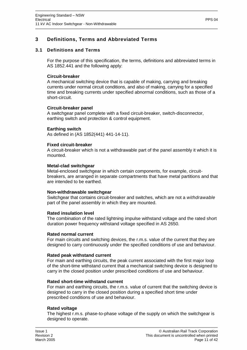
For the purpose of this specification, the terms, definitions and abbreviated terms inAS 1852.441 and the following apply:
Circuit-breakerA mechanical switching device that is capable of making, carrying and breakingcurrents under normal circuit conditions, and also of making, carrying for a specifiedtime and breaking currents under specified abnormal conditions, such as those of ashort-circuit.
Circuit-breaker panelA switchgear panel complete with a fixed circuit-breaker, switch-disconnector,earthing switch and protection & control equipment.
Earthing switchAs defined in (AS 1852(441) 441-14-11).
Fixed circuit-breakerA circuit-breaker which is not a withdrawable part of the panel assembly it which it ismounted.
Metal-clad switchgearMetal-enclosed switchgear in which certain components, for example, circuit-breakers, are arranged in separate compartments that have metal partitions and thatare intended to be earthed.
Non-withdrawable switchgearSwitchgear that contains circuit-breaker and switches, which are not a withdrawablepart of the panel assembly in which they are mounted.
Rated insulation levelThe combination of the rated lightning impulse withstand voltage and the rated shortduration power frequency withstand voltage specified in AS 2650.
Rated normal currentFor main circuits and switching devices, the r.m.s. value of the current that they aredesigned to carry continuously under the specified conditions of use and behaviour.
Rated peak withstand currentFor main and earthing circuits, the peak current associated with the first major loopof the short-time withstand current that a mechanical switching device is designed tocarry in the closed position under prescribed conditions of use and behaviour.
Rated short-time withstand currentFor main and earthing circuits, the r.m.s. value of current that the switching device isdesigned to carry in the closed position during a specified short time underprescribed conditions of use and behaviour.
Rated voltageThe highest r.m.s. phase-to-phase voltage of the supply on which the switchgear isdesigned to operate.
Engineering Standard–NSWElectrical PPS 0411 kV AC Indoor Switchgear - Non-Withdrawable
Issue 1 © Australian Rail Track CorporationRevision 2 This document is uncontrolled when printedMarch 2005 Page 12 of 42
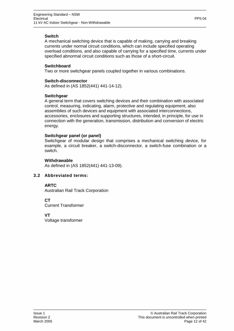
SwitchA mechanical switching device that is capable of making, carrying and breakingcurrents under normal circuit conditions, which can include specified operatingoverload conditions, and also capable of carrying for a specified time, currents underspecified abnormal circuit conditions such as those of a short-circuit.
SwitchboardTwo or more switchgear panels coupled together in various combinations.
Switch-disconnectorAs defined in (AS 1852(441) 441-14-12).
SwitchgearA general term that covers switching devices and their combination with associatedcontrol, measuring, indicating, alarm, protective and regulating equipment, alsoassemblies of such devices and equipment with associated interconnections,accessories, enclosures and supporting structures, intended, in principle, for use inconnection with the generation, transmission, distribution and conversion of electricenergy.
Switchgear panel (or panel)Switchgear of modular design that comprises a mechanical switching device, forexample, a circuit breaker, a switch-disconnector, a switch-fuse combination or aswitch.
WithdrawableAs defined in (AS 1852(441) 441-13-09).
3.2 Abbreviated terms:
ARTCAustralian Rail Track Corporation
CTCurrent Transformer
VTVoltage transformer

Engineering Standard–NSWElectrical PPS 0411 kV AC Indoor Switchgear - Non-Withdrawable
Issue 1 © Australian Rail Track CorporationRevision 2 This document is uncontrolled when printedMarch 2005 Page 13 of 42
4 Background
ARTC operates a high voltage AC network in which the nominal voltages used are 11kV, 33kV, 66kV and 132kV. ARTC also operates a 1500V DC network that suppliespower for electric traction. The ARTC high voltage distribution system operates at 11kV and supplies railway signaling stations and other loads along the rail corridor.There is also a rapidly diminishing 2.2 kV network.
The ARTC 11 kV system comprises both overhead lines and underground cable.System substations are either out door or indoor. Indoor arrangements are preferredfor new construction.
Distribution substations are either poll mounted, kiosks (pad mount), or indoor.
5 Functional Characteristics
The 11 kV indoor switchgear covered by this standard shall:
Provide an 11 kV busbar and busbar voltage transformer.
Provide for connection of 11 kV feeders, bus tie cables, systemtransformer, and distribution transformer circuits to the 11 kV busbar.
Provide for isolation and earthing of feeders, bus tie cables, systemtransformer, and distribution transformer circuits.
Provide protection and control for 11 kV feeders, systemtransformer, and distribution transformer circuits and sections onthe 11 kV busbar.
Provide the means to perform a DC cable test on the HV cables, withoutdisturbing existing HV cable connections.
Note: There is no requirement to provide a facility to earth the busbar.
Engineering Standard–NSWElectrical PPS 0411 kV AC Indoor Switchgear - Non-Withdrawable
Issue 1 © Australian Rail Track CorporationRevision 2 This document is uncontrolled when printedMarch 2005 Page 14 of 42
6 Performance Characteristics
6.1 General
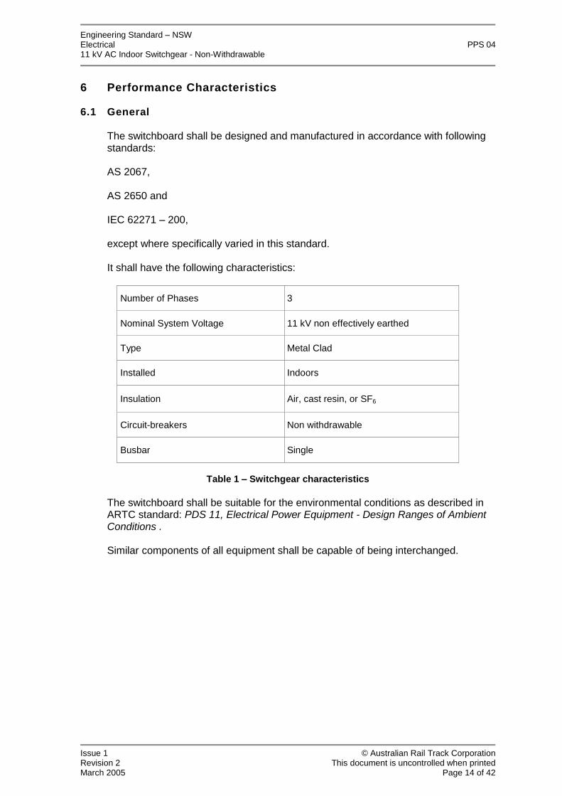
The switchboard shall be designed and manufactured in accordance with followingstandards:
AS 2067,
AS 2650 and
IEC 62271–200,
except where specifically varied in this standard.
It shall have the following characteristics:
Number of Phases 3
Nominal System Voltage 11 kV non effectively earthed
Type Metal Clad
Installed Indoors
Insulation Air, cast resin, or SF6
Circuit-breakers Non withdrawable
Busbar Single
Table 1 –Switchgear characteristics
The switchboard shall be suitable for the environmental conditions as described inARTC standard: PDS 11, Electrical Power Equipment - Design Ranges of AmbientConditions .
Similar components of all equipment shall be capable of being interchanged.

Engineering Standard–NSWElectrical PPS 0411 kV AC Indoor Switchgear - Non-Withdrawable
Issue 1 © Australian Rail Track CorporationRevision 2 This document is uncontrolled when printedMarch 2005 Page 15 of 42
6.2 Switchboard Ratings
The switchgear shall have the following general ratings:
Rating Type Rating
Rated voltage 12 kV
Line to Earth Voltage Rating Suitable for RestivelyEarthed System
Rated frequency 50Hz
Rated Normal Current - Busbar 630 or 1250 amps (min)
400A,
630A,
Rated Normal Current - Feeder, Transformer and Bus Tie CircuitBreaker Panels
(steps as per R10 series defined in IEC 60059)800A or
Rated Insulation Level:
Minimum Rated peak lightning impulse withstand voltage 75 Peak kV
Rated short-duration power-frequency withstand r.m.s voltage 28kV
Rated short-time withstand current Ik 12.5, 16, 20, 25kA
Rated peak withstand current Ip=2.5Ik 31.5, 40, 50, 63kA
Rated duration of short-time current tk 3 second
Rated Short Circuit Breaking Current 12.5, 16, 20, 25kA
Rated Short Circuit Making Current 31.5, 40, 50, 63kA
Rated operating sequence O - 0.3s-CO-3min-CO
AFLRInternal Arc Classification
(As per IEC 62271-200, Annex A; Defined 3.132) Internal arc 12.5, 16,20, 25kA, 3s
Table 2 - Switchgear Ratings
Engineering Standard–NSWElectrical PPS 0411 kV AC Indoor Switchgear - Non-Withdrawable
Issue 1 © Australian Rail Track CorporationRevision 2 This document is uncontrolled when printedMarch 2005 Page 16 of 42
7 Technical Characteristics
7.1 General
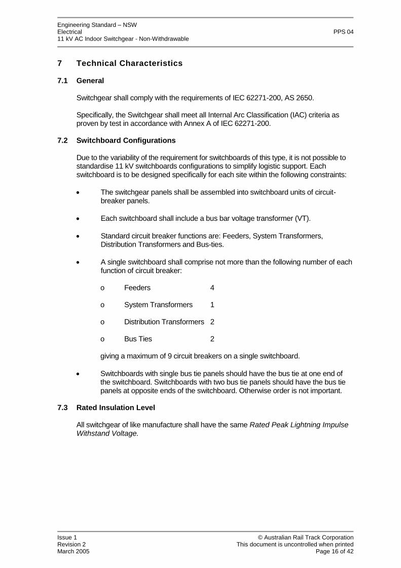
Switchgear shall comply with the requirements of IEC 62271-200, AS 2650.
Specifically, the Switchgear shall meet all Internal Arc Classification (IAC) criteria asproven by test in accordance with Annex A of IEC 62271-200.
7.2 Switchboard Configurations
Due to the variability of the requirement for switchboards of this type, it is not possible tostandardise 11 kV switchboards configurations to simplify logistic support. Eachswitchboard is to be designed specifically for each site within the following constraints:
The switchgear panels shall be assembled into switchboard units of circuit-breaker panels.
Each switchboard shall include a bus bar voltage transformer (VT).
Standard circuit breaker functions are: Feeders, System Transformers,Distribution Transformers and Bus-ties.
A single switchboard shall comprise not more than the following number of eachfunction of circuit breaker:
o Feeders 4
o System Transformers 1
o Distribution Transformers 2
o Bus Ties 2
giving a maximum of 9 circuit breakers on a single switchboard.
Switchboards with single bus tie panels should have the bus tie at one end ofthe switchboard. Switchboards with two bus tie panels should have the bus tiepanels at opposite ends of the switchboard. Otherwise order is not important.
7.3 Rated Insulation Level
All switchgear of like manufacture shall have the same Rated Peak Lightning ImpulseWithstand Voltage.
Engineering Standard–NSWElectrical PPS 0411 kV AC Indoor Switchgear - Non-Withdrawable
Issue 1 © Australian Rail Track CorporationRevision 2 This document is uncontrolled when printedMarch 2005 Page 17 of 42
7.4 Control Voltage –DC auxiliary supply voltage
The auxiliary supply voltage shall be 120 V d.c.(nominal).
Auxiliary supply voltage requirements are specified in PDS 12, CommonRequirements for Electric Power Equipment.
7.5 Busbar
All joints and tees in busbars and busbar connections shall be made with an approvedconnection type.
If bolts, nuts and washers are used they shall be suitably protected against corrosion inaccordance with ISO 9227.
Putty and tape shall not be used.
7.6 Gas insulation (where applicable)
Sulfur-hexafluoride (SF6) insulated switchgear shall be filled with SF6 that complieswith the requirements of IEC 60376.
The switchgear shall be factory sealed so as to not require any routine gasreplenishment during installation or in normal service.
The design, construction and sealing of gas compartments shall be such that the gaswill not require replenishment for 20 years.
It is preferred that switchgear that that requires gassing after panels are assembled into switchboards be gassed at the factory and transported to site as a single unit.
Only if specifically approved by ARTC, shall gas compartments be assembled,gassed and sealed on site. In this situation the supplier shall test the tightness, inaccordance with AS 2650 clause 6.1, and shall certify and warrant for gas tightness.
A device for monitoring the SF6 pressure in each gas compartment while in serviceshall be provided. This device shall provide indication of the minimum permissiblepressure level for safe operation and shall provide two level alarms - level 1 alarm,level 2 alarm and operation inhibit. The pressure level monitoring device shall beclearly visible to the operator from the operating side of the switchgear panel.
7.7 Earthing bar
To assist with stray current mitigation measures from the dc traction system, it maybe necessary to connect 11 kV cable screens to a separate cable screen earth bar.This arrangement is to facilitate future installation of a transient earth clamp. Thetransient clamp acts as a DC decoupler, to provide DC isolation between earthingpoints that are still AC connected. Under an AC earth fault the clamp impedancemomentarily changes state to a virtual short circuit, acting to provide a directconnection of HV cable screens to the switchboard earth bar. The transient earthclamp provides a blocking path to dc stray current that could otherwise use thecable screen as a path.

Engineering Standard–NSWElectrical PPS 0411 kV AC Indoor Switchgear - Non-Withdrawable
Issue 1 © Australian Rail Track CorporationRevision 2 This document is uncontrolled when printedMarch 2005 Page 18 of 42
Note some HV panels will require all HV earth screens to be directly connected tothe switchboard earth bar.
Each switchgear panel shall include two copper earthing bars, rated for maximumfault levels and not less than 120 mm2 cross section area to facilitate earthing.
The cable screen earth bar shall be connected to the switchboard earth bar viaremovable links and shall be isolated from similar bars in adjacent panels. It shall beinsulated from the frame of the switchboard by insulated mounts that have beenrated for maximum earth potential rise and tested for at least 15kV for 1 minute. Thecable screen earth bar shall provide for connection of the two removable links, fourHV cable screens and mounting holes for a transient earth clamp.
The switchboard earth bar shall interconnect adjacent switchgear panels andprovide:-
for all switchgear bonding
for two cable connections to the main substation earth grid
for two removable links per panel for connection to the insulated earth screenearthing bar (per panel)
for connection of four HV cable screens
mounting holes for a transient earth clamp
To provide for mounting of the transient earth clamp the two earth bars, ie theswitchboard earth bar and the cable screen earth bar, shall be vertically separatedas far as possible to provide sufficient space for future insertion of the transientearth clamps.
Earth termination requirements are provided in PDS 12, Common Requirements forElectric Power Equipment.
7.8 HV Cable Interface
Each circuit-breaker panel shall be equipped with a HV cable compartment providinga dead-break, separable, insulated and shielded system for connection of HVcables. The separable insulated shielded connection system is to be compliant withAS 2629 and relevant ratings specified in the table of Table 2 at section 6.2Switchboard Ratings. At least two single core XLPE insulated 11 kV cables perphase of up to 240mm2 cross section shall be accommodated. The required cablenumber and size per phase, switchboard configuration type and circuit breaker/cableconnection rated current will be specified at placement of order.
The cables shall enter the cable compartment from below. The minimum of twocables shall be achieved without sacrificing space for surge arrester equipment ifrequired. The non standard configuration is top entry of power cables. Somesituations may require this configuration. Details of the cable connections shall benominated in the Technical Schedule at Appendix A

Engineering Standard–NSWElectrical PPS 0411 kV AC Indoor Switchgear - Non-Withdrawable
Issue 1 © Australian Rail Track CorporationRevision 2 This document is uncontrolled when printedMarch 2005 Page 19 of 42
The cable termination shall be capable of withstanding the power frequency test asspecified in Table 1 of AS 2650.
Each circuit breaker panel is to provide the means to perform a DC cable test on theHV cables, without disturbing existing HV cable connections. See section 7.21Circuit Test Facilities.
7.9 Surge arresters
The switchgear may be installed with short cable feeds from overhead lines.Sufficient space shall be provided within the cable compartment of each feedercubicle to install surge diverters if required for the specific feeding configuration.Surge arrester type and restrictions shall be nominated in the Technical Schedule atAppendix A.
7.10 Current Transformers
The circuit-breaker panels shall be provided with three phase sets of protectioncurrent transformers and three phase sets of metering current transformers incompliance with PDS 09 Protection System Requirements for the High VoltageNetwork.
7.11 Voltage Transformers
7.11.1 General
A three-phase, voltage transformer in compliance with PDS 09, Protection SystemRequirements for the High Voltage Network shall be provided for each switchboard.
For maintenance, and for the commissioning of protection relays, it shall be possibleto simulate the voltage conditions that would occur during earth faults and thesupplier shall explain how this is achieved (see the Technical Schedule at AppendixA Item 49). A typical way to achieve this is to remove the high-voltage fuse in anyone phase and earth that phase of the voltage transformer.
7.11.2 Directional Protection Supply Alarm
Within each panel the low voltage side of the voltage transformer supply shall beprotected by a separate circuit-breaker of adequate breaking capacity complete withvoltage free contacts. The main voltage transformer secondary circuit-breakershould discriminate for faults protected by the individual panel circuit breakers. Foreach section of the busbar the normally closed auxiliary contacts shall be wired inseries to provide a single ‘directional protection alarm’ in accordance with PDS 09,Protection System Requirements for the High Voltage Network, clause 4.6Protection alarms.

Engineering Standard–NSWElectrical PPS 0411 kV AC Indoor Switchgear - Non-Withdrawable
Issue 1 © Australian Rail Track CorporationRevision 2 This document is uncontrolled when printedMarch 2005 Page 20 of 42
7.11.3 Voltage Transformer Alarm
A three phase, phase failure relay in compliance with PDS 09, Protection Systemrequirements for the High Voltage Network shall be connected to the secondary ofthe voltage transformer.
7.12 Circuit-Breakers
7.12.1 General
Circuit-breaker panels shall comprise a fixed circuit breaker, switch-disconnectorand earthing switch.
Circuit-breakers shall comply with the requirements of AS 2650 and IEC 62271 –100.
Circuit-breakers, switch-disconnectors and earthing switches that have longmechanical and electrical endurance (as defined in IEC 62271 parts 100 & 102) arepreferred.
The protection and control equipment shall be located in or immediately above therelevant circuit breaker panel. Details of the required protection schemes arespecified in ARTC standard PDS 09–Protection System requirements for the highvoltage network. The switchboard shall incorporate the applicable requirements ofPDS 09.
7.12.2 Circuit Breaker Type
The interrupting medium shall be either vacuum or SF6.
7.12.2.1 Vacuum Circuit-Breakers
Means shall be provided for testing the units for loss of vacuum without thenecessity of removal of the units.
The contacts of the interrupter shall be held open by a positive fail-safe deviceindependent of interrupter vacuum. The closing arrangement shall be designedso as to give a positive closing action whilst overcoming the contact hold opendevice.
7.12.2.2 SF6 Circuit-breakers
Each circuit breaker shall consist of three separate "pole units" mounted on asingle piece frame and shall be mechanically interconnected. The design of theinterrupting mechanism and contacts shall be such that the energy dissipated inthe SF6 gas is low and does not cause appreciable degradation of gas.
Each pole shall be provided with a separate and independent set of main andarcing contacts to minimise degradation of main contacts during fault interruption.The arcing contacts shall be terminated by tungsten or similar tips and shall be ofa high electrical endurance. The main contacts shall be capable of carrying themaximum short circuit current without damage. If butt type arcing contacts areprovided, it shall be possible to check the wear of arcing contacts without thenecessity to open pole units.

Engineering Standard–NSWElectrical PPS 0411 kV AC Indoor Switchgear - Non-Withdrawable
Issue 1 © Australian Rail Track CorporationRevision 2 This document is uncontrolled when printedMarch 2005 Page 21 of 42
The internal surfaces of all porcelains shall not be glazed.
The circuit breakers shall be guaranteed to have a leakage rate of less than 1%mass per year of the quantity of SF6 used for filling. Means shall be provided tocheck the internal pressure of the pole units.
The gas tightness shall be obtained by elimination of any part likely to wear orage.
Certificates and details of tests for tightness carried out on pole units of breakersshall be maintained.
7.12.3 Circuit-breaker operating mechanisms
The circuit-breaker operating mechanism shall be an integral part of the circuitbreaker.
Any part of the circuit breaker mechanism that requires routine inspection andmaintenance shall not be enclosed in any gas tight compartment.
Solenoid based mechanisms are subject to ARTC approval. A full failure mode andreliability analysis is required for approval. Spring charging motors are preferred.
All circuit breakers in the closed position shall be able to trip-close-trip before thespring needs to be charged again.
All circuit breaker panels shall be the XEM type (stored energy operation by meansof energy stored in a motor-charged spring with manual or electrical release).
7.12.4 Circuit-breaker Operation and Control
The circuit-breaker closing mechanism shall be electrically operated, trip-free. Thecircuit-breaker mechanism shall provide lockout preventing closing, as specified inClause 441-14-23 of AS 1852 (441) - 1985
The circuit breakers shall be arranged for operation by local control or by remotesupervisory control. The supervisory equipment will provide an open or closecommand signal of 1.0 A maximum at the nominated DC control voltage for up to1.0 second.
The circuit breaker shall close without delay when the close command signal isapplied. While this command signal is applied, the circuit breaker shall not make asecond attempt to close if it fails to close on the first attempt.
The circuit breaker shall open without delay when the open command signal isapplied independently to any of the trip coils or to all trip coils simultaneously.
A mechanical push-button or similar device for tripping the circuit breaker shall beprovided.
Continuously rated control equipment to make the successful closing of the circuit-breaker independent of the length of time that the control switch is held in theCLOSE position and to ensure that only one closing attempt can be made if thecontrol switch is held in the CLOSE position.

Engineering Standard–NSWElectrical PPS 0411 kV AC Indoor Switchgear - Non-Withdrawable
Issue 1 © Australian Rail Track CorporationRevision 2 This document is uncontrolled when printedMarch 2005 Page 22 of 42
7.12.5 Circuit-breaker operation coils
All operating coils of the control contactors associated with the solenoid-operatedclosing device shall be rated for continuous operation.
7.13 Indication
The circuit-breaker panel shall have indication clearly visible from the front of thepanel (i.e. either on the circuit breaker or on the circuit-breaker panel).
The circuit-breaker switchgear panel shall have the following definite indication:
a) Circuit-breaker open/close;b) Switch disconnector open/close (if applicable);c) Earth switch position;d) Stored energy device charged/discharged;e) Non-resettable mechanical operation counter.
7.14 Interlocks
Facilities provided for operational access to parts of the switchgear panel thatcontain live components shall be mechanically interlocked so that access to suchparts is not possible unless all live parts have been rendered safe, either by a visiblyapplied earth connection or by being positively disconnected and screened from theremaining live parts.
Mechanical interlocks shall be provided to ensure positive and substantial protectionagainst malfunction, and shall be so designed and constructed as to ensuredependable fail-safe operation.
Interlocks shall ensure that the disconnector cannot be moved or operated unlessthe circuit breaker is open.
Interlocks shall ensure that the circuit breaker cannot be closed unless thedisconnector is fully in the “closed”, “isolated” or “earth” position.
Positive mechanical interlocking shall be provided to prevent inadvertent switchingfrom the ON position to the EARTH position without a definite stop in the OFFposition, or from the EARTH position to the ON position without a definite stop in theOFF position.
Access to the test terminals shall only be possible when the associated earth switchis in the EARTH position.
When the circuit test facility is in use, it shall not be possible to close thedisconnector.
It is preferred that the making of the disconnector contacts in the EARTH positionshall be directly observable by the operator.
If the earthing of a circuit-breaker panel is not visible from the operating position, thecorresponding indication shall be directly coupled to the earthing mechanism, toensure fail-safe indication.
Engineering Standard–NSWElectrical PPS 0411 kV AC Indoor Switchgear - Non-Withdrawable
Issue 1 © Australian Rail Track CorporationRevision 2 This document is uncontrolled when printedMarch 2005 Page 23 of 42
If the switchgear panel is designed so that the circuit to be earthed is earthedthrough the main contacts of the circuit breaker, then the circuit breaker must beinterlocked so that it cannot be tripped by the protection relays or SCADA controlwhile the circuit is earthed.
An analysis shall be provided detailing the integrity of the interlocking system. Theanalysis shall include all possible failure modes and the controls employed to preventan unsafe operation.
A table shall be produced of all possible and inhibited states the switchgearmay occupy.
7.15 Circuit Earthing Facilities
Each panel shall be equipped with circuit earthing switches manufactured andtested in accordance with IEC 62271-102.
Earth switches shall be the integral type.
The earthing system shall be designed and tested for making a live circuit with aprospective peak fault current of 31.25kA.Each circuit-earthing switch shall bemechanically interlocked with the corresponding circuit breaker in accordance withsection 7.14 Interlocks of this specification.
The earthing switch shall be rated for fault making if:
the circuit to be earthed, is earthed through the main contacts of the circuit-breaker, AND
if there is any identified failure mode which could result in the earth switchbeing closed onto a live circuit.
Each switch shall be provided with a failsafe indicating device to positively indicatewhether it is in the OPEN OR EARTH position and the words "OPEN" and "EARTH"shall be used for the respective indication of these positions.
If the equipment is configured to allow the position of the disconnector contacts in theEARTH position to be directly observable, then appropriate illumination shall beprovided. The preferred light source is white LED’s. It shall be possible to replace thelight source without the need for isolating and HV equipment or significantdisassembly of the switchgear.
7.16 Padlocking
Facilities shall be provided to padlock:
The circuit-breaker in the open positions and the closed positionwhile the disconnector is in the earthed position, and
The disconnector in the closed, open and earth positions.
The circuit test facility, if applicable (see section 7.14 Interlocks and 7.21Circuit Test Facilities)
All padlocking facilities shall be suitable for padlocks with a 6 mm shank diameter.

Engineering Standard–NSWElectrical PPS 0411 kV AC Indoor Switchgear - Non-Withdrawable
Issue 1 © Australian Rail Track CorporationRevision 2 This document is uncontrolled when printedMarch 2005 Page 24 of 42
7.17 Auxiliary Equipment
Each switchgear panel, shall be fitted with:
(a) A control panel with :
(i) A local CLOSE and OPEN switch or push-buttons coloured red andgreen respectively.
(ii) LOCAL - SUPERVISORY changeover switch;
(iii) Capability for installation of instrumentation to measure:
Voltage
Current
Energy
The requirement for which instruments are to be installed shall bespecified at the time of order.
The requirements of any instrumentation to be fitted, are set out insection 7.18 Instruments, Transducers and Metering
(iv) Live line indicators shall be provided for each of the three phases oneach circuit and the busbar. Live line indicators shall comply with therequirements of IEC 61958.
(b) Two normally open and two normally closed auxiliary switches rated at 5amperes in a 120 V d.c. inductive circuit or a 415 V a.c. circuit. (Theseauxiliary switches shall be provided in addition to those essential to thecircuit-breaker operation).
(c) A mechanically operated indicator, indelibly marked, to show whether thecircuit breaker is open or closed. The word OPEN shall be visible only if thecircuit breaker is open and the word CLOSED shall be visible only if thecircuit breaker is closed. If colours are used in addition, then the colour greenshall indicate the open condition and the colour red shall indicate the closedcondition.
(d) Electrically operated indicating lights of the LED type.
(e) A non-resettable operation counter.
(f) A set of terminals for the termination of auxiliary wiring. All auxiliary wiringsuch as for remote closing and tripping circuits, incoming DC control suppliesand all spare auxiliary switches shall be connected to these terminals.
(g) Mechanical interlocks shall be provided in compliance with clause 5.11 ofIEC 62271-200 to prevent unsafe operation, including:
(1) Automatic opening of a circuit-breaker when it is used to earth acircuit or the bus bar

Engineering Standard–NSWElectrical PPS 0411 kV AC Indoor Switchgear - Non-Withdrawable
Issue 1 © Australian Rail Track CorporationRevision 2 This document is uncontrolled when printedMarch 2005 Page 25 of 42
(2) Closing of an earthing switch unless the circuit-breaker is in the openposition
Each switchboard shall be fitted with a voltmeter to indicate the bus voltage.
7.18 Instruments, Transducers and Metering
7.18.1 General
All instruments, transducers and metering equipment that are required to be fittedshall comply with this section and the relevant requirements in PDS 12, CommonRequirements for Electric Power Equipment.
All indicating instruments shall be flush-mounted industrial type instruments thatcomply with the requirements of the relevant of IEC standards: IEC 60051-1, IEC60051-2, IEC 60051-3, IEC 60051-7, IEC 60051-8 and IEC 60051-9. Theinstruments shall be clearly visible and easily readable from a standing position infront of the panel.
Scales shall have a scale length of at least 90 mm. All instruments on a switchboardshall be scaled with the same type of characters of the same size.
All current-operated instruments shall be protected against continuous over currentup to 120% of nominal value and high current surges up to the fault rating of thecircuitbreaker.
7.18.2 Transducers
Current measurements made for SCADA shall use the protection CTs to generatethe measurements. Only one current measurement transducer per phase may beinterposed between the CT and the protection relay. The approved transducers tobe used to measure current are of the 0–20mA type and are specified in ARTCstandard: PDS 09, Protection System Requirements for the High Voltage Network.The output of the current transducer shall be used to also drive the ammeter unlessthe transducer cannot drive both the ammeter and the SCADA measurementcircuits. If the ammeter would impose excessive burden on the transducer thenseparate CTs must be used for metering.
It is preferred that a suitable ammeter should be selected to avoid the need foradditional metering CTs.
7.18.3 Ammeters
Ammeters shall have analogue indication with scales that are essentially linear withthe scale selected for the instrument accuracy class.
Ammeter scales shall allow for 120% of the primary current rating of the currenttransformer.
The current transformer ratio shall be clearly marked on the face of the ammeter.
The accuracy of ammeters shall be 3 % or better and shall be stated in theTechnical Schedule.

Engineering Standard–NSWElectrical PPS 0411 kV AC Indoor Switchgear - Non-Withdrawable
Issue 1 © Australian Rail Track CorporationRevision 2 This document is uncontrolled when printedMarch 2005 Page 26 of 42
7.18.4 Voltmeters
Voltmeter shall have analogue indication with scales that have an indicating rangeof 80 % to 120 % of the nominal system voltages.
Where voltmeters that have a nominal range from 0 % to 120 % are required, this willbe specified at time of order.
The nominal voltage shall be marked in red on the scale.
7.18.5 Watthour meter
kWh meters shall be three phase, with pulse output. The pulse output rate shall be10 per kWh. Where required for revenue metering the kWh meter is to beconnected to a metering CT of suitable rating and accuracy class.
7.19 Busbar and Circuit Protection
7.19.1 General
Protection schemes shall be in accordance with ARTC specification PDS 09 -Protection System Requirements for the High Voltage Network.
7.19.2 Feeder Protection
Primary feeder protection shall be feeder pilot wire.
The feeder protection scheme on incoming feeders shall provide a means ofimplementing inter-tripping with circuit breakers at the supply end of the feederwhere placement of protection CTs leaves a blind spot on the feeder side of thecircuit breaker. The inter-trip scheme shall be implemented in accordance withspecification PDS 09, Protection System Requirements for the High VoltageNetwork.
If implemented via dedicated inter-trip, then one set of voltage free normally openand normally closed contacts rated to switch 1 Amp at 120V dc shall be providedwhere the feeder can be an incoming feeder. Circuit breakers for feeders that canbe arranged as outgoing shall be configured to accept an inter-trip signal.
7.19.3 System Transformer Protection
The relays and associated equipment for the protection of system transformers arenormally located with the protection and control equipment for the higher voltagewinding. The 11 kV circuit breaker panel for a system transformer shall therefore beconfigured for connection to the required protection equipment located elsewhere.

Engineering Standard–NSWElectrical PPS 0411 kV AC Indoor Switchgear - Non-Withdrawable
Issue 1 © Australian Rail Track CorporationRevision 2 This document is uncontrolled when printedMarch 2005 Page 27 of 42
7.19.4 Distribution Transformer Protection
The protection functions required for distribution transformers shall be implementedwithin the 11 kV panel. Inputs from gas relays / gas over pressure voltage freecontacts, low voltage equipment voltage free contacts and high temperature RTD’s inputs shall form part of the tripping circuit of the circuit breaker.
Where a differential scheme is required terminals shall be provided for theconnection of current transformers on the secondary side of the transformer and theprotection equipment shall provide a trip output to trip the low voltage circuit breaker.
An over-current scheme for protection of downstream equipment shall be provided.
Engineering Standard–NSWElectrical PPS 0411 kV AC Indoor Switchgear - Non-Withdrawable
Issue 1 © Australian Rail Track CorporationRevision 2 This document is uncontrolled when printedMarch 2005 Page 28 of 42
7.20 SCADA Indications and Controls
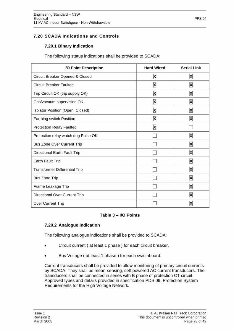
7.20.1 Binary Indication
The following status indications shall be provided to SCADA:
I/O Point Description Hard Wired Serial Link
Circuit Breaker Opened & Closed X X
Circuit Breaker Faulted X X
Trip Circuit OK (trip supply OK) X X
Gas/vacuum supervision OK X X
Isolator Position (Open, Closed) X X
Earthing switch Position X X
Protection Relay Faulted X
Protection relay watch dog Pulse OK X
Bus Zone Over Current Trip X
Directional Earth Fault Trip X
Earth Fault Trip X
Transformer Differential Trip X
Bus Zone Trip X
Frame Leakage Trip X
Directional Over Current Trip X
Over Current Trip X
Table 3 –I/O Points
7.20.2 Analogue Indication
The following analogue indications shall be provided to SCADA:
Circuit current ( at least 1 phase ) for each circuit breaker.
Bus Voltage ( at least 1 phase ) for each swicthboard.
Current transducers shall be provided to allow monitoring of primary circuit currentsby SCADA. They shall be mean-sensing, self-powered AC current transducers. Thetransducers shall be connected in series with B phase of protection CT circuit.Approved types and details provided in specification PDS 09, Protection SystemRequirements for the High Voltage Network.

Engineering Standard–NSWElectrical PPS 0411 kV AC Indoor Switchgear - Non-Withdrawable
Issue 1 © Australian Rail Track CorporationRevision 2 This document is uncontrolled when printedMarch 2005 Page 29 of 42
7.20.3 Controls
The following control functions from the SCADA system are to be provided for:
Circuit Breaker Open (trip).
Circuit Breaker Close.
7.21 Circuit Test Facilities
Each circuit-breaker panel shall incorporate an integral type circuit test facility.All test facilities shall be suitable for the application of d.c. test voltages associatedwith the after-installation testing of power cables, and shall be rated for the samesystem voltage as the switchgear.
The test facility shall facilitate the connection of test equipment with the circuitearthed and then allow the earths to be removed with the test equipment stillconnected.
It shall be possible to connect a hand applied earthing set to the circuit side of eachcircuit breaker panel for use in conjunction with test equipment. It shall be possibleto apply or remove the earth connection independent of the application or removalof the test equipment connection. It is permissible that external removableaccessories be used to achieve this function.
8 Integrated System Support Requirements
8.1 Integrated Support Objectives
The switchgear manufacturer must establish and provide the information required tooperate and maintain the equipment throughout its operational life, in a costeffective manner and to a level that is consistent with the planned operationalperformance and usage of the switchgear.
This includes:
Specifying Maintenance Requirements,
Spares Support,
Operations and Maintenance Manuals,
Training, and
Support Equipment and Tooling.
8.2 Equipment Supplier Deliverable
The Integrated support requirements are a significant deliverable in the procurementof new Switchgear. Manuals, training, documentation and other supportdeliverable's shall be in accordance with POP 01, Electrical Power Equipment -Integrated Support Requirements.
Engineering Standard–NSWElectrical PPS 0411 kV AC Indoor Switchgear - Non-Withdrawable
Issue 1 © Australian Rail Track CorporationRevision 2 This document is uncontrolled when printedMarch 2005 Page 30 of 42
9 Tests
Testing requirements are to be read in conjunction with the specification PDS 12,Common Requirements for Electric Power Equipment.
9.1 Routine tests
Routine tests as listed in:
AS 2650, Clause 7
IEC 62271-100, Clause 7
IEC 62271-200, Clause 7 Shall be carried out on each panel.
9.2 Type tests
The results of type tests as required in:
AS 2650 IEC 62271-100 I EC 62271-200 Shall be made available by the supplier upon request.
Test certificate details, demonstrating compliance with the above standards, includingthe date, results and name of the testing body shall be supplied in the TechnicalSchedule at Appendix A.
Type test certificates for each of these tests will be accepted where it can bedemonstrated that the switchgear supplied is of a similar design to previously typetested switchgear.

Engineering Standard–NSWElectrical PPS 0411 kV AC Indoor Switchgear - Non-Withdrawable
Issue 1 © Australian Rail Track CorporationRevision 2 This document is uncontrolled when printedMarch 2005 Page 31 of 42
10 Data Set associated with the Equipment
The following data shall be supplied by the manufacturer and maintained for theswitchgear. This data will remain the property of ARTC.
10.1 Information
Information requirements are to be read in conjunction with the specification:
POP 01, Electrical Power Equipment–Integrated Support Requirements.
PDS 12, Common Requirements for Electric Power Equipment.
PDS 09, Protection System Requirements for High Voltage Network.
10.2 Technical Schedule at Appendix A
The information listed in the technical schedule at Appendix A, supplied by themanufacturer, shall be maintained for each switchboard.
10.3 Life Cycle Costing
All the data and assumptions pertaining to the determination of the whole-of-life costcalculations shall be recorded.

Engineering Standard–NSWElectrical PPS 0411 kV AC Indoor Switchgear - Non-Withdrawable
Issue 1 © Australian Rail Track CorporationRevision 2 This document is uncontrolled when printedMarch 2005 Page 32 of 42
Appendix A - Technical Schedule
The manufacturer shall supply the information listed in this technical schedule.
Item Description Tenderer SuppliedInformation
1 Switchgear information:
a) manufacturer
b) country of origin
c) catalogue/type designation
d) total switchgear mass, kg
2 Circuit breaker type SF6 / Vacuum
3 Switchboard - General arrangementdrawing showing overall dimensions (h, w,d in mm), cable termination locations andrequired space around unit for access andarc venting requirements for :
Single circuit-breaker panel
Total length of switchboard with busVT and arc duct (if applicable)
Required clearances at sides andrear of switchboard.
Required clearance at front ofswitchboard for installation andremoval
Required clearances on top ofswitchboard
Cable trench width
Depth of protrusions into cabletrench (if applicable)
Total mass of switchgear

Engineering Standard–NSWElectrical PPS 0311kV AC Indoor Switchgear - Non-Withdrawable
Issue 1 © Australian Rail Track CorporationRevision 2 This document is uncontrolled when printedMarch 2005 Page 33 of 42
Item Description Tenderer SuppliedInformation
4 Switchgear Ratings:
Voltage, kV
Busbar Normal Current
Circuit Breaker(s)
Insulation Level:
Peak lightning impulsewithstand voltage
Short duration power frequencywithstand voltage
Short time withstand current Ik
Peak withstand current Ip
Duration of short time current Tk
Short circuit breaking current
Short circuit making current
5 Ambient conditions assumed for statedcurrent ratings above and applicablederating values for ambient of 50°C
6 Current ratings of switchgear at worst caseambient conditions given in ARTCspecification: PDS 11 ElectricalPower Equipment–Design Ranges ofAmbient Conditions

Engineering Standard–NSWElectrical PPS 0311kV AC Indoor Switchgear - Non-Withdrawable
Issue 1 © Australian Rail Track CorporationRevision 2 This document is uncontrolled when printedMarch 2005 Page 34 of 42
Item Description Tenderer SuppliedInformation
7 Switchgear IEC Classifications:
Internal arc classification
Internal arc test current, kA Internalarc test duration
Circuit breaker mechanical durabilityclass
Circuit breaker electrical durabilityclass
Switch disconnector mechanicaldurability class
Switch disconnector electricaldurability class
Earth switch mechanical durabilityclass
Earth switch electrical durabilityclass
8 Details of lifting and slinging for individualpanels
9 Surge arrester types accommodated
10 Surge arrester mountingdetails/restrictions.

Engineering Standard–NSWElectrical PPS 0311kV AC Indoor Switchgear - Non-Withdrawable
Issue 1 © Australian Rail Track CorporationRevision 2 This document is uncontrolled when printedMarch 2005 Page 35 of 42
Item Description Tenderer SuppliedInformation
11 Reliability Data:
Failure Modes (for early, Normal life &wear out periods)
Mean Operating Hours between failuremodes
Mean Time To Repair. Provide details ofany special requirements, test andsupportequipment etc
Number of units in service in Australia
Period (years) this model/type has beenavailable for purchase
Number of units in service worldwide
12 Description of the panel busbarinterconnection arrangements
13 Description of all operational and safetyinterlocking arrangements.
14 Table of all possible and inhibited states thatthe circuit breakers and switches in theswitchgear may occupy.
15 Analysis demonstrating the integrity of allinterlocking arrangements which includes ananalysis of all possible failure modes and thecontrols designed in to manage them
16 Auxiliary supply voltage
17 Is the switchgear self powered? Yes/No
1 8 Clearance hole or stud size of earthing bar offered
19 Gas used for insulation
20 In which compartments are the gas used?
21 Detail of gas pressure monitoring device.

Engineering Standard–NSWElectrical PPS 0311kV AC Indoor Switchgear - Non-Withdrawable
Issue 1 © Australian Rail Track CorporationRevision 2 This document is uncontrolled when printedMarch 2005 Page 36 of 42
Item Description Tenderer SuppliedInformation
22 Quantity of the SF6 to be usedin each separately filledcompartment?
23 Specify the degree of SF6 gastightness for the switchgear.
24 If the circuit-breaker is a vacuum typestate the method of indicating vacuumloss (if any)
25 Does the circuit-breaker panel includein-line off-load disconnectors?
26 Is the switch disconnector offered 2-way or3-way?
2 or 3
27 Details of the circuit earthing facilities offeredincluding the method of indicating the positionof the earthing switch and guaranteeing theintegrity of that indication.
28 Diameter of the clamping screw
29 Supply voltage, peak power andsteady power of the springs chargemotor (where applicable)
30 Type of circuit-breaker closingmechanism offered
31 Rating of each circuit-breaker closing device
32 Voltage and peak power ratings forthe continuous operation of the circuit-breaker coils
33 Is a solenoid circuit-breaker operatingmechanism is an option and if so what is itspower rating
34 Number of circuit breaker spare auxillarycontacts
35 Type of circuit test facility offered
36 Describe the test plugs

Engineering Standard–NSWElectrical PPS 0311kV AC Indoor Switchgear - Non-Withdrawable
Issue 1 © Australian Rail Track CorporationRevision 2 This document is uncontrolled when printedMarch 2005 Page 37 of 42
Item Description Tenderer SuppliedInformation
37 Type of switch-disconnector offered
38 Type of test facility offered
39 Maximum size and number of HV cablesthat can be terminated in each circuit-breaker panel. Clearly specify clearancesbetween each cable termination of eachphase. Provision of a detailed dimensioneddrawing of the arrangement is required.
40 Type of cable termination offered. Specifymanufacturer, model and full details ofseparable insulated connector. Detailshielding arrangement to be included.
41 Peak and stand-by power requirements ofthe switchgear, VA
42 Type and ratings of live line indicators
43 CT and VT space limitations andmounting arrangements (for CTsprovide details for both bus and circuitsides of the circuit breaker).
44 Can the busbar VTs beaccommodated in circuit-breakerpanels?
45 If busbar VTs cannot be mounted in thecircuit breaker panel then describe themounting arrangement and dimensions

Engineering Standard–NSWElectrical PPS 0311kV AC Indoor Switchgear - Non-Withdrawable
Issue 1 © Australian Rail Track CorporationRevision 2 This document is uncontrolled when printedMarch 2005 Page 38 of 42
Item Description Tenderer SuppliedInformation
46 Number and Details of the CurrentTransformers offered for each function:
a) type
b) encapsulation material
c) class
d) burden, VA
e) tap ratios
f) tap points
g) knee-point voltage
h) secondary resistance
i) excitation current at knee-point voltage
47 Details of terminal block/rail mountedterminals offered for current transformers
48 Type of test block offered
49 Details of method(s) for simulation ofsystem faults during test & commissioningof directional relays.

Engineering Standard–NSWElectrical PPS 0311kV AC Indoor Switchgear - Non-Withdrawable
Issue 1 © Australian Rail Track CorporationRevision 2 This document is uncontrolled when printedMarch 2005 Page 39 of 42
Item Description Tenderer SuppliedInformation
50 Details of voltage transformers offered:
a) name of manufacturer
b) withdrawable or non-withdrawable
c) ratio
d) class
e) burden,VA
f) voltage factor
g) location of fuses
h) type of fuses
i) location of test blocks
j) 3 limb or 5 limb
k) primary connection at busbar or circuitside
51 Location of fuses, MCCBs or links
52 Type of VT test blocks offered
53 Description of protection equipment
54 Details of protection equipment offered:
a) manufacturer
b) type
c) rating
55 Details of points, test burden and current forroutine accuracy tests on current andvoltage transformers
56 Details of instruments offered
57 Details of transducers offered
58 Details of metering equipment offered

Engineering Standard–NSWElectrical PPS 0311kV AC Indoor Switchgear - Non-Withdrawable
Issue 1 © Australian Rail Track CorporationRevision 2 This document is uncontrolled when printedMarch 2005 Page 40 of 42
Item Description Tenderer SuppliedInformation
59 Details of indicators offered
60 Details of switchgear internal wiringidentification
61 Describe LV termination and cableaccess arrangements
62 Details of terminal blocks offered
63 Rating plate attachment method
64 Labels attachment method
65 Details of coatings provided
66 Colours of custom coatings available
67 Details of serial control interface protocol, ifavailable, on integrated panel andprotection control equipment.

Engineering Standard–NSWElectrical PPS 0311kV AC Indoor Switchgear - Non-Withdrawable
Issue 1 © Australian Rail Track CorporationRevision 2 This document is uncontrolled when printedMarch 2005 Page 41 of 42
Appendix B - RFT Checklist
B1 Application
The following material is for guidance in the preparation of a Request for Tender forthis type of equipment. This checklist itself is not intended to directly form part of anycontract.
This section to be read in conjunction with the RFT Checklist in specification PDS 12,Common Requirements for Electric Power Equipment.
B2 Information to be supplied to the Tenderer
Where this document is used as the basis for procurement of equipment fora particular location, in addition to the general requirements in this standardthe following information related to the particular site will need to be supplied:
Requirement for specific deliverables including:
o Installation and on-site operational testing if to be carried out bythe supplier
o Recovery and replenishment of SF6 gas after its service life(must be rendered by the supplier of SF6 switchgear).
o Two spare sets of fuses for each voltage transformer.
Number and type of switchboard configuration selected shall include:
o The number and type of panel required in each switchboard.
o The continuous current rating of feeder, transformer and bus tiecircuit breaker panel selected.
o The number of sets and specification of the CTs and protectionscheme. Refer to ARTC PDS 09, Protection System Requirements forthe High Voltage Network.
o HV cable connection ratings.
o The required number of cables and size per phase, per panel shallbe specified at time of order.
o The specific configuration of instruments, transducers and meteringequipment (voltage, current and energy), to be installed onswitchgear panels shall be specified at the time of order.
Any required restrictions on the dimensions or placement of the switchgear.
Location specific surge arrester requirements.
Notice that the contractor will be required to provide appropriate seals for 11kV receptacles to prevent contamination during storage and transport.

Engineering Standard–NSWElectrical PPS 0311kV AC Indoor Switchgear - Non-Withdrawable
Issue 1 © Australian Rail Track CorporationRevision 2 This document is uncontrolled when printedMarch 2005 Page 42 of 42
Notice that the provisionally selected tenderer will be required to provideaccess to a sample panel and full set of wiring diagrams for evaluation of theinterlocking of the isolate/earth switch by ARTC’s interlocking experts (signals discipline).
B3 Information to be Sought From the Tenderer
Integrated Support information as per ARTC Standard
Alternate offers for solenoid based mechanisms.
Tenders to complete and submit Technical Schedule at Appendix A