PP-H Ball valve - socket fusion w/electric actuator · Polypropylene (PP) piping systems are widely...
16
CEPEX EXTREME SERIES DATASHEETS PP-H Ball valve - socket fusion w/electric actuator Válvula de bola en CPVC - termofusión hembra c/ actuador eléctrico PRODUCT RANGE Sizes from DN10 up to DN100 Working pressure at 20°C (73°F) water temperature: D16 – D63 : PN 10 (150 psi) D75 – D110 : PN 6 (90 psi) O-rings in: EPDM (perox.) or FPM (FKM) Standards: ISO-DIN Certifications: CE Options: Safety Block, Digital Positioning System CODES RANGO DE GAMA Medidas desde DN10 hasta DN100 Presión de servicio a 20°C (73°F) temperatura de agua: D16 – D63 : PN 10 (150 psi) D75 – D110 : PN 6 (90 psi) Juntas en: EPDM (perox.) o FPM (FKM) Standards: ISO-DIN Certificaciones: CE Opciones: Bloque Seguridad, Sistema Posicionador Digital CÓDIGOS * KV 100 (l/min, Δp = 1 bar) 0045 0045 DN PN D EPDM FPM Kv 85-240V 24V 85-240V 24V 10 10 16 6491009J 6491010J 6516609J 6516610J 75 l/min 15 10 20 6491109J 6491110J 6516709J 6516710J 190 l/min 20 10 25 6491209J 6491210J 6516809J 6516810J 380 l/min 25 10 32 6491309J 6491310J 6516909J 6516910J 690 l/min 32 10 40 6491409J 6491410J 6517009J 6517010J 980 l/min 40 10 50 6491509J 6517109J 1600 l/min 50 10 63 6491609J 6517209J 3000 l/min 65 6 75 6692709J 6754209J 5500 l/min 80 6 90 6692809J 6754309J 6800 l/min 100 6 110 6850909J 6850910J 6851009J 6851010J 8900 l/min
Transcript of PP-H Ball valve - socket fusion w/electric actuator · Polypropylene (PP) piping systems are widely...
CEPEX EXTREME SERIES DATASHEETS
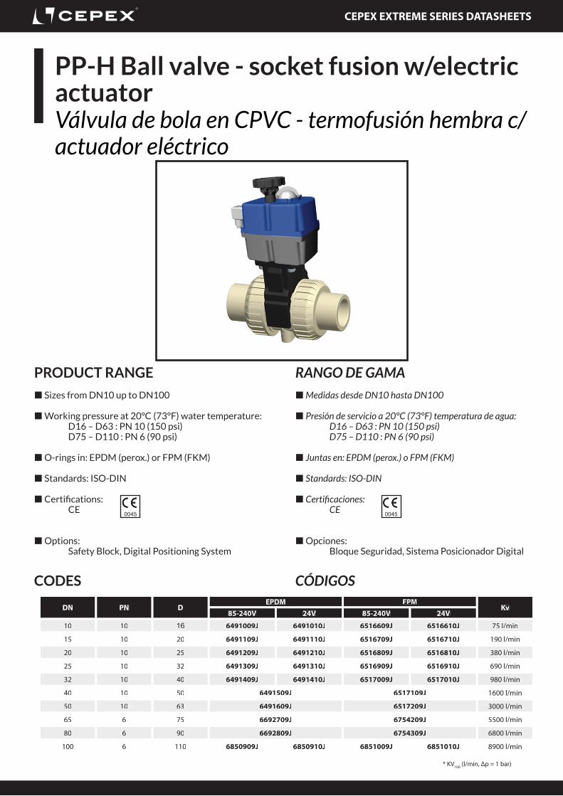
PP-H Ball valve - socket fusion w/electric actuatorVálvula de bola en CPVC - termofusión hembra c/actuador eléctrico
PRODUCT RANGE
Sizes from DN10 up to DN100
Working pressure at 20°C (73°F) water temperature: D16 – D63 : PN 10 (150 psi) D75 – D110 : PN 6 (90 psi)
O-rings in: EPDM (perox.) or FPM (FKM)
Standards: ISO-DIN
Certifi cations: CE
Options: Safety Block, Digital Positioning System
CODES
RANGO DE GAMA Medidas desde DN10 hasta DN100
Presión de servicio a 20°C (73°F) temperatura de agua: D16 – D63 : PN 10 (150 psi) D75 – D110 : PN 6 (90 psi)
Juntas en: EPDM (perox.) o FPM (FKM)
Standards: ISO-DIN
Certifi caciones: CE
Opciones: Bloque Seguridad, Sistema Posicionador Digital
CÓDIGOS
* KV100 (l/min, Δp = 1 bar)
0045 0045
DN PN DEPDM FPM
Kv85-240V 24V 85-240V 24V
10 10 16 6491009J 6491010J 6516609J 6516610J 75 l/min
15 10 20 6491109J 6491110J 6516709J 6516710J 190 l/min
20 10 25 6491209J 6491210J 6516809J 6516810J 380 l/min
25 10 32 6491309J 6491310J 6516909J 6516910J 690 l/min
32 10 40 6491409J 6491410J 6517009J 6517010J 980 l/min
40 10 50 6491509J 6517109J 1600 l/min
50 10 63 6491609J 6517209J 3000 l/min
65 6 75 6692709J 6754209J 5500 l/min
80 6 90 6692809J 6754309J 6800 l/min
100 6 110 6850909J 6850910J 6851009J 6851010J 8900 l/min
CEPEX EXTREME SERIES DATASHEETS
Material propertiesPropiedades del material
• Temperature range: 5°C a 80°C in continous working. Nominal pressure in function of the temeprature according diagramm..• High impact ressitance. High toghness.• Good insulating.• Light weight.• High thermal expansion.• Non toxic and taint-free. Suitable for food and drinking use.• Resistant to acids, alkalis, salts and organic solutions.• Ideal for installations above or below ground.• Jointing by thread, socket fusion or butt welding.• Not resistant to concentred oxidising acids.
• Rango de temperaturas: 5°C a 80°C en trabajo continuo. Presión nominal en función de la temperatura según gráfico.• Alta resistencia al impacto. Alta tenacidad.• Buen aislante.• Peso reducido.• Alta expansión térmica.• No tóxico y libre de corrosión. Apto para uso alimentario.• Resistente a ácidos, alcalinos, sales y soluciones orgánicas.• Ideal para instalaciones exteriores o enterradas.• Posible union roscada, por termofusión o soldadura a tope.• No resistente a ácidos oxidantes concentrados.
PPDESCRIPTION
Polypropylene (PP) piping systems are widely used in industrial processing. Light in weight yet with high impact strength and reliable heat fusion welding, PP also offers good abrasion resistance and is a good thermal and electrical insulator.PP is suitable for working use at temperatures up to 80°C, and will withstand short term use at a maximum 110°C.Chemical resistance is excellent: PP is resistant to aqueous solutions of acids, alkalis and salts, and to a large number of organic solvents.
PPDESCRIPCIÓN
Los sistemas de conducción en polipropileno (PP) son ampliamente usados en procesos industriales. De peso reducido y de gran resistencia al impacto son capaces de ser soldados, el PP también ofrece gran resistencia a la abrasión y es buen aislante térmico y eléctrico.El PP puede trabajar en temperaturas de hasta 80ºC y, a corto plazo, puede soportar hasta 110ºC.Su resistencia química es excelente: es resistente a soluciones acuosas de ácidos, alcalinos y sales, y a un gran número de disolventes orgánicos.
CEPEX EXTREME SERIES DATASHEETS
Features and BenefitsCaracterísticas y Benefi cios
FEATURES BENEFITS
“Anti-block” system Avoid the ball blocking due to overstrength in the seal-carrier.Makes easier the in-line maintenance.
Threaded seal-carrier Allows system maintenance without emptying the system
Ergonomic handle with rubber anti-slipping surface Maximum resistance and improved torque
SS reinforcement in all female threaded unions Possibility of threading metal parts without mechanical problems
Threaded inserts (SS) for wall-mounting and actuator installation Easy to install, easy to motorise. Easy conversion manual/automatic.
Machined and polished ball Avoid the ball blocking due to dirt particles in the fl uid. Long live.
Machined shaft Perfect operation and leaking proof
Double shaft o-ring Valve installation in any position
100% traceability: serial and batch number Minimize the problems or maximize the solutions
Laser marking of the valve characteristics Easy to see the characteristics and long live, no easy to unstick labels.
Water and air testing in 100% of the valves Minimum errors in the fi nished product
CARACTERÍSTICAS BENEFICIOS
Sistema “Anti-block” Impide el bloqueo de la bola al sobre apretar el porta-juntas. Facilita el mantenimiento en línea.
Porta-juntas roscado Permite el matenimiento del sistema sin necesidad de vaciar la instalación
Maneta ergonómica y superfície anti-deslizante Máxima resistencia y mejora de par de cierre
Refuerzo en acero inoxidable en todas las uniones rosca hembra Posibilidad de roscar elementos metálicos sin problemas mecánicos
Insertos roscados (INOX) para montaje en pared y acoplamiento de actuadores Fácil instalación, fácil motorización. Fácil conversión manual/automática.
Bola mecanizada y pulida Evita el bloqueo de la bola en presencia de partículas de suciedad en el líquido. Larga vida.
Eje mecanizado Operación perfecta y a prueba de fugas
Doble junta tórica en el eje Posibilidad de instalación de la válvula en cualquier posición
Trazabilidad 100%: número de lote y de serie Minimiza los problemas y maximiza las soluciones
Marcado láser de las características de las válvulas Facilidad para consultar las caracterísitcas y larga vida, sin etiquetas fácil de despegar.
Test de fugas con agua y aire al 100% de las válvulas Mínimo índice de errores en el producto completo
CEPEX EXTREME SERIES DATASHEETS
Design regulationsNormativas de diseño
Ap
plic
atio
ns
and
ch
arac
teri
stic
sA
plic
acio
nes y
ca
ract
erís
tica
s
Reg
ula
tio
ns
Reg
ulac
ione
sM
ater
ials
Mat
eria
les
Test
Prue
ba
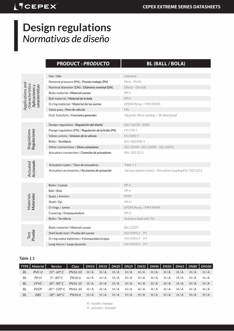
PRODUCT - PRODUCTO BL (BALL / BOLA)
Use / Uso Industrial
Nominal pressure (PN) / Presión trabajo (PN) PN 6 - PN10
Nominal diameter (DN) / Diámetro nominal (DN) DN10 – DN100
Body material / Material cuerpo PP-H
Ball material / Material de la bola PP-H
O-ring material / Material de las juntas EPDM Perox. / FPM (FKM)
Valve pass / Paso de válvula DN
Gral. functions / Funciones generales IQuarter. All or nothing / Bi-directional
Design regulation / Regulación del diseño ISO /16135 : 2006
Flange regulation (PN) / Regulación de la brida (PN) EN 558-1
Valves unions / Uniones de la válvula EN 1092-1
Bolts / Tornillería EN / ISO 898-1
Other connections / Otras conexiones ISO 15494 - ISO 15493 – ISO 10931
Actuators connection / Conexión de actuadores EN / ISO 5211
Body material / Material cuerpo EN 12107
Shell body test / Prueba del cuerpo ISO 9393-2 P.5
O-ring water tightness / Estanqueidad al agua ISO 9393-2 P.7
Long therm / Larga duración ISO 9393-2 P.7
Body / Cuerpo PP-H
Ball / Bola PP-H
Seats / Asientos PTFE
Shaft / Eje PP-H
O-rings / Juntas EPDM Perox. / FPM (FKM)
Covering / Empaquetadura PP-H
Bolts / Tornillería Stainless Steel (A4-70)
Act
uat
edA
ccio
nado Actuation types / Tipos de actuadores Table 1.1
Actuation accessories / Accesorios de actuación Various options (sizes) / Actuation coupling EN / ISO 5211
Table 1.1
TYPE Material Service Class DN10 DN15 DN20 DN25 DN32 DN40 DN50 DN65 DN80 DN100
BL PVC-U 10º - 60º C PN16-10 H / A H / A H / A H / A H / A H / A H / A H / A H / A H / A
BL PP-H 5º - 80º C PN10-6 H / A H / A H / A H / A H / A H / A H / A H / A H / A H / A
BL CPVC 10º - 80º C PN16-10 H / A H / A H / A H / A H / A H / A H / A H / A H / A H / A
BL PVDF -20 º -120º C PN16-10 H / A H / A H / A H / A H / A H / A H / A H / A H / A H / A
BL ABS -30º - 60º C PN10-6 H / A H / A H / A H / A H / A H / A H / A H / A H / A H / A
H - handle / manetaA - actuator / actuador
CEPEX EXTREME SERIES DATASHEETS
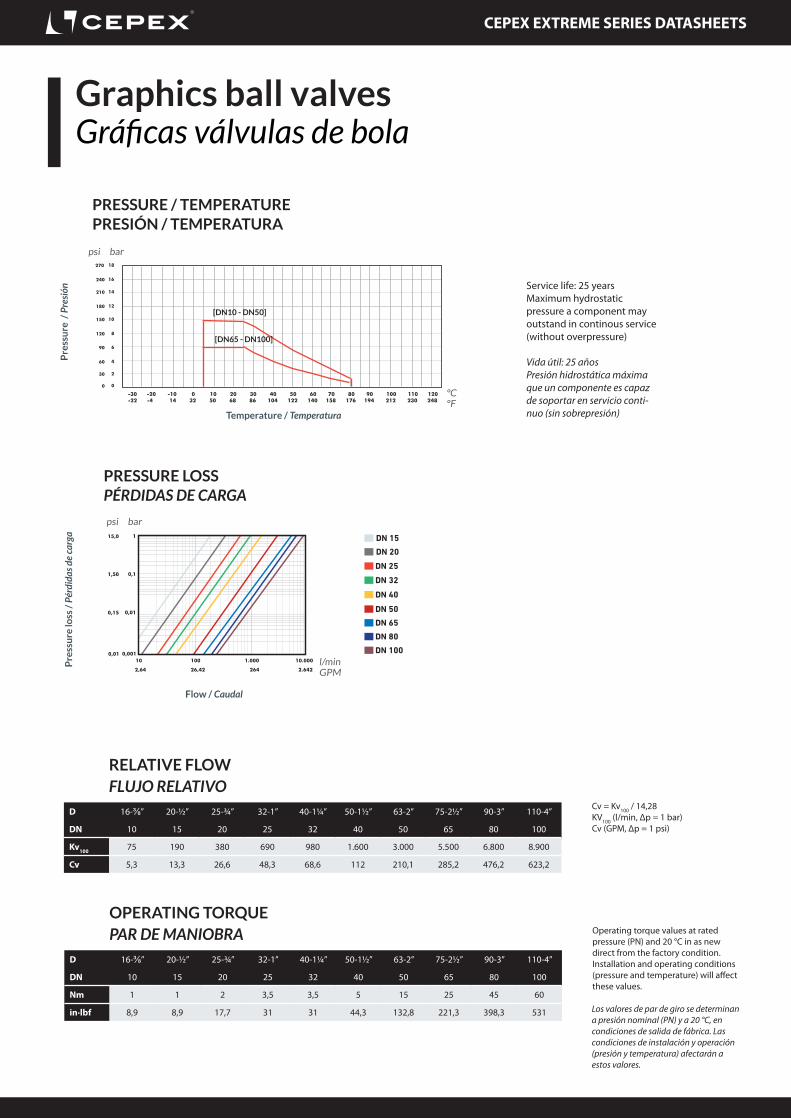
Graphics ball valvesGráficas válvulas de bola
DN 20
DN 25
DN 32
DN 40
DN 50
PRESSURE LOSSPÉRDIDAS DE CARGA
Pre
ssu
re lo
ss /
Pér
dida
s de
carg
a
Flow / Caudal
DN 65
DN 80
DN 100
DN 15
psi bar
l/minGPM
PRESSURE / TEMPERATUREPRESIÓN / TEMPERATURA
Pre
ssu
re /
Pre
sión
Temperature / Temperatura
psi bar
ºCºF
OPERATING TORQUEPAR DE MANIOBRA
D 16-⅜” 20-½” 25-¾” 32-1” 40-1¼” 50-1½” 63-2” 75-2½” 90-3” 110-4”
DN 10 15 20 25 32 40 50 65 80 100
Nm 1 1 2 3,5 3,5 5 15 25 45 60
in·lbf 8,9 8,9 17,7 31 31 44,3 132,8 221,3 398,3 531
Vida útil: 25 añosPresión hidrostática máxima que un componente es capaz de soportar en servicio conti-nuo (sin sobrepresión)
Service life: 25 yearsMaximum hydrostatic pressure a component may outstand in continous service (without overpressure)
Operating torque values at rated pressure (PN) and 20 °C in as new direct from the factory condition. Installation and operating conditions (pressure and temperature) will affect these values.
Los valores de par de giro se determinan a presión nominal (PN) y a 20 °C, en condiciones de salida de fábrica. Las condiciones de instalación y operación (presión y temperatura) afectarán a estos valores.
RELATIVE FLOWFLUJO RELATIVO
D 16-⅜” 20-½” 25-¾” 32-1” 40-1¼” 50-1½” 63-2” 75-2½” 90-3” 110-4”
DN 10 15 20 25 32 40 50 65 80 100
Kv100 75 190 380 690 980 1.600 3.000 5.500 6.800 8.900
Cv 5,3 13,3 26,6 48,3 68,6 112 210,1 285,2 476,2 623,2
Cv = Kv100 / 14,28KV100 (l/min, Δp = 1 bar)Cv (GPM, Δp = 1 psi)
[DN10 - DN50]
[DN65 - DN100]
CEPEX EXTREME SERIES DATASHEETS
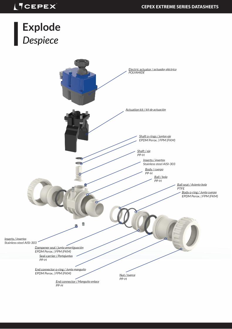
Electric actuator / actuador eléctricoPOLYAMIDE
Actuation kit / kit de actuación
ExplodeDespiece
Shaft o-rings / juntas ejeEPDM Perox. | FPM (FKM)
Shaft / ejePP-H
Inserts / insertosStainless steel AISI-303
Body / cuerpoPP-H
Ball / bolaPP-H
Ball seat / Asiento bolaPTFE
Body o-ring / Junta cuerpoEPDM Perox. | FPM (FKM)
Nut / tuercaPP-H
End connector / Manguito enlacePP-H
End connector o-ring / Junta manguitoEPDM Perox. | FPM (FKM)
Seal-carrier / PortajuntasPP-H
Dampener seal / junta amortiguaciónEPDM Perox. | FPM (FKM)
Inserts / insertosStainless steel AISI-303
CEPEX EXTREME SERIES DATASHEETS
Body o-ring / Junta cuerpoEPDM Perox. | FPM (FKM)
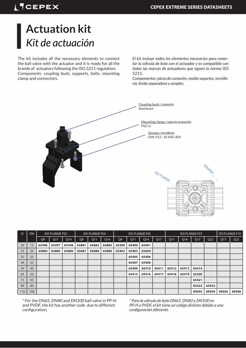
Coupling bush / conexiónAluminum
Mounting clamp / soporte actuaciónPVC-U
Screws / tornilleríaDIN-912 - SS AISI-304
Actuation kitKit de actuación
The kit includes all the necessary elements to connect the ball valve with the actuator and it is ready for all the brands of actuators following the ISO 5211 regulation.Components: coupling bush, supports, bolts, mounting clamp and connectors.
El kit incluye todos los elementos necesarios para conec-tar la válvula de bola con el actuador y es compatible con todas las marcas de actuadores que siguen la norma ISO 5211.Componentes: pieza de conexión, medio soportes, tornille-ría, brida separadora y acoples.
ISO FLANGE
HE
IGH
T
SQUARE
D DN ISO FLANGE F03 ISO FLANGE F04 ISO FLANGE F05 ISO FLANGE F07 ISO FLANGE F10
Q9 Q11 Q14 Q9 Q11 Q14 Q9 Q11 Q14 Q17 Q11 Q14 Q17 Q22 Q17 Q22
20 15 65396 65397 65398 65881 65882 65883 65399 65400 65401
25 20 65884 65885 65886 65887 65888 65889 65402 65403 65404
32 25 65405 65406
40 32 65407 65408
50 40 65409 65410 65411 65412 65413 65414
63 50 65415 65416 65417 65418 65419 65420
75 65 65421
90 80 65422 65423
110 100 69503 69504 69505 69506
* For the DN65, DN80 and DN100 ball valve in PP-H and PVDF, the kit has another code due to different configuration.
* Para la válvula de bola DN65, DN80 y DN100 en PP-H y PVDF, el kit tiene un código distinto debido a una configuración diferente.
CEPEX EXTREME SERIES DATASHEETS
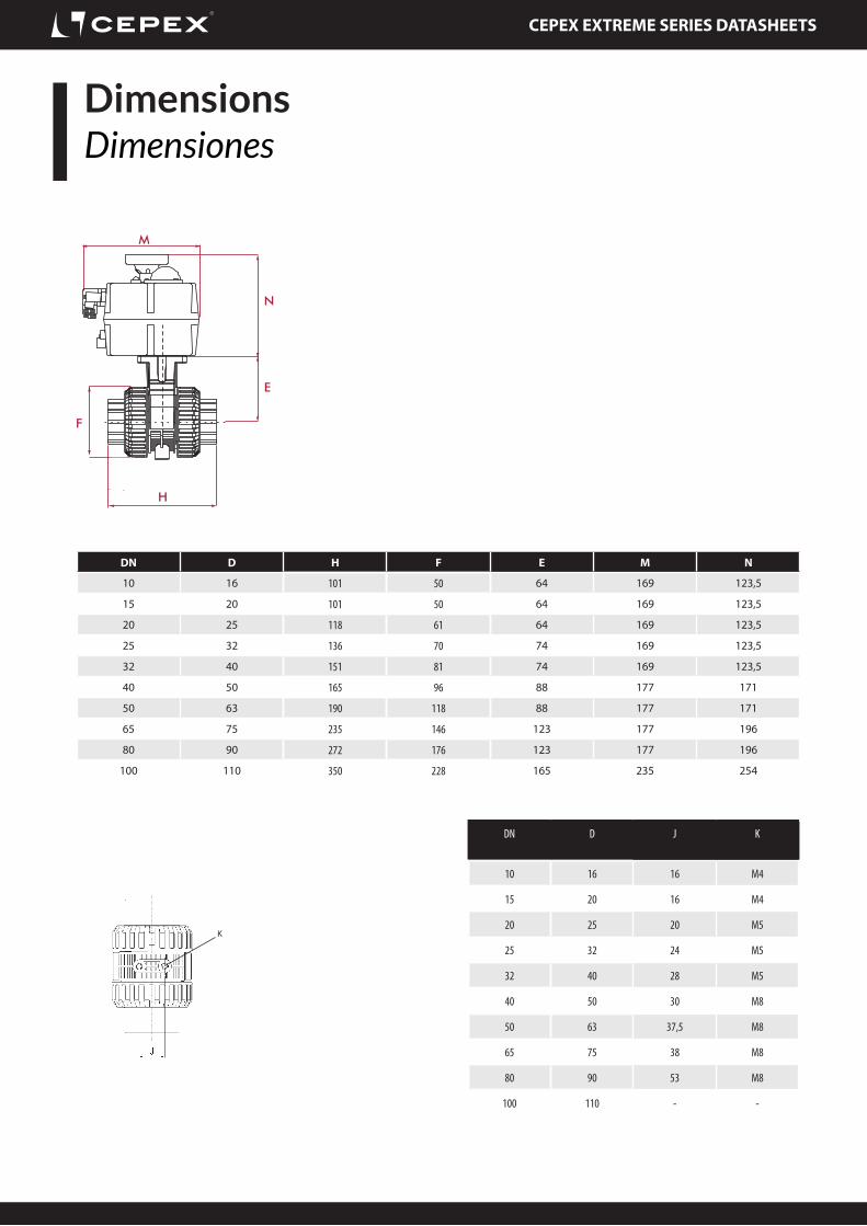
DimensionsDimensiones
K
DN D J K
10 16 16 M4
15 20 16 M4
20 25 20 M5
25 32 24 M5
32 40 28 M5
40 50 30 M8
50 63 37,5 M8
65 75 38 M8
80 90 53 M8
100 110 - -
DN D H F E M N
10 16 101 50 64 169 123,5
15 20 101 50 64 169 123,5
20 25 118 61 64 169 123,5
25 32 136 70 74 169 123,5
32 40 151 81 74 169 123,5
40 50 165 96 88 177 171
50 63 190 118 88 177 171
65 75 235 146 123 177 196
80 90 272 176 123 177 196
100 110 350 228 165 235 254
HL
F
E
M
N
CEPEX EXTREME SERIES DATASHEETS
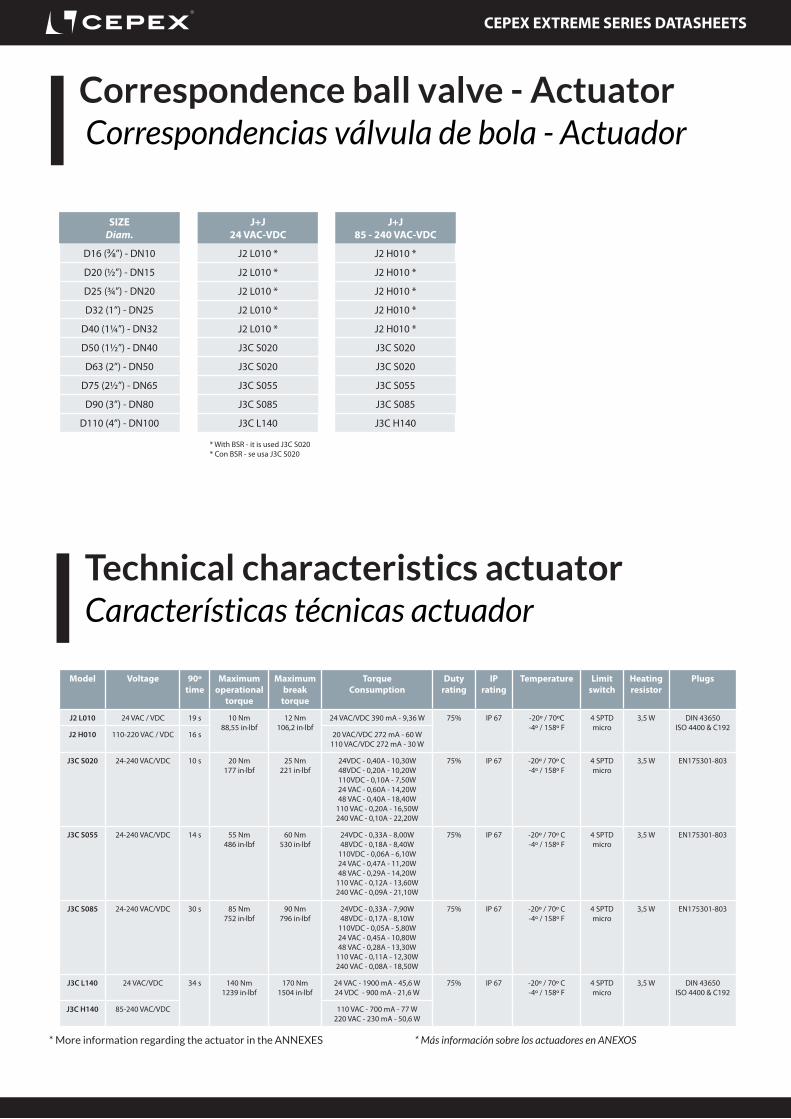
Technical characteristics actuatorCaracterísticas técnicas actuador
Model Voltage 90º time
Maximum operational
torque
Maximum break
torque
Torque Consumption
Duty rating
IP rating
Temperature Limit switch
Heating resistor
Plugs
J2 L010 24 VAC / VDC 19 s 10 Nm88,55 in·lbf
12 Nm106,2 in·lbf
24 VAC/VDC 390 mA - 9,36 W 75% IP 67 -20º / 70ºC-4º / 158º F
4 SPTD micro
3,5 W DIN 43650ISO 4400 & C192
J2 H010 110-220 VAC / VDC 16 s 20 VAC/VDC 272 mA - 60 W110 VAC/VDC 272 mA - 30 W
J3C S020 24-240 VAC/VDC 10 s 20 Nm177 in·lbf
25 Nm221 in·lbf
24VDC - 0,40A - 10,30W48VDC - 0,20A - 10,20W110VDC - 0,10A - 7,50W24 VAC - 0,60A - 14,20W48 VAC - 0,40A - 18,40W
110 VAC - 0,20A - 16,50W240 VAC - 0,10A - 22,20W
75% IP 67 -20º / 70º C-4º / 158º F
4 SPTD micro
3,5 W EN175301-803
J3C S055 24-240 VAC/VDC 14 s 55 Nm486 in·lbf
60 Nm530 in·lbf
24VDC - 0,33A - 8,00W48VDC - 0,18A - 8,40W
110VDC - 0,06A - 6,10W24 VAC - 0,47A - 11,20W48 VAC - 0,29A - 14,20W
110 VAC - 0,12A - 13,60W240 VAC - 0,09A - 21,10W
75% IP 67 -20º / 70º C-4º / 158º F
4 SPTD micro
3,5 W EN175301-803
J3C S085 24-240 VAC/VDC 30 s 85 Nm752 in·lbf
90 Nm796 in·lbf
24VDC - 0,33A - 7,90W48VDC - 0,17A - 8,10W
110VDC - 0,05A - 5,80W24 VAC - 0,45A - 10,80W48 VAC - 0,28A - 13,30W
110 VAC - 0,11A - 12,30W240 VAC - 0,08A - 18,50W
75% IP 67 -20º / 70º C-4º / 158º F
4 SPTD micro
3,5 W EN175301-803
J3C L140 24 VAC/VDC 34 s 140 Nm1239 in·lbf
170 Nm1504 in·lbf
24 VAC - 1900 mA - 45,6 W24 VDC - 900 mA - 21,6 W
75% IP 67 -20º / 70º C-4º / 158º F
4 SPTD micro
3,5 W DIN 43650ISO 4400 & C192
J3C H140 85-240 VAC/VDC 110 VAC - 700 mA - 77 W220 VAC - 230 mA - 50,6 W
SIZEDiam.
J+J24 VAC-VDC
J+J85 - 240 VAC-VDC
D16 (⅜”) - DN10 J2 L010 * J2 H010 *
D20 (½”) - DN15 J2 L010 * J2 H010 *
D25 (¾”) - DN20 J2 L010 * J2 H010 *
D32 (1”) - DN25 J2 L010 * J2 H010 *
D40 (1¼”) - DN32 J2 L010 * J2 H010 *
D50 (1½”) - DN40 J3C S020 J3C S020
D63 (2”) - DN50 J3C S020 J3C S020
D75 (2½”) - DN65 J3C S055 J3C S055
D90 (3”) - DN80 J3C S085 J3C S085
D110 (4”) - DN100 J3C L140 J3C H140
* With BSR - it is used J3C S020* Con BSR - se usa J3C S020
* More information regarding the actuator in the ANNEXES * Más información sobre los actuadores en ANEXOS
Correspondence ball valve - Actuator Correspondencias válvula de bola - Actuador
CEPEX EXTREME SERIES DATASHEETS
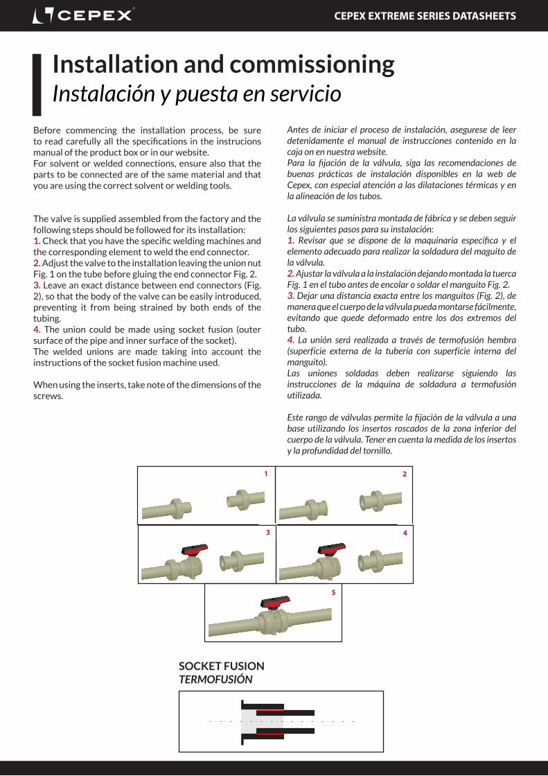
Installation and commissioningInstalación y puesta en servicio
Before commencing the installation process, be sure to read carefully all the specifications in the instrucions manual of the product box or in our website. For solvent or welded connections, ensure also that the parts to be connected are of the same material and that you are using the correct solvent or welding tools.
The valve is supplied assembled from the factory and the following steps should be followed for its installation:1. Check that you have the specific welding machines and the corresponding element to weld the end connector.2. Adjust the valve to the installation leaving the union nut Fig. 1 on the tube before gluing the end connector Fig. 2.3. Leave an exact distance between end connectors (Fig. 2), so that the body of the valve can be easily introduced, preventing it from being strained by both ends of the tubing.4. The union could be made using socket fusion (outer surface of the pipe and inner surface of the socket).The welded unions are made taking into account the instructions of the socket fusion machine used.
When using the inserts, take note of the dimensions of the screws.
Antes de iniciar el proceso de instalación, asegurese de leer detenidamente el manual de instrucciones contenido en la caja on en nuestra website.Para la fijación de la válvula, siga las recomendaciones de buenas prácticas de instalación disponibles en la web de Cepex, con especial atención a las dilataciones térmicas y en la alineación de los tubos.
La válvula se suministra montada de fábrica y se deben seguir los siguientes pasos para su instalación:1. Revisar que se dispone de la maquinaria específica y el elemento adecuado para realizar la soldadura del maguito de la válvula.2. Ajustar la válvula a la instalación dejando montada la tuerca Fig. 1 en el tubo antes de encolar o soldar el manguito Fig. 2.3. Dejar una distancia exacta entre los manguitos (Fig. 2), de manera que el cuerpo de la válvula pueda montarse fácilmente, evitando que quede deformado entre los dos extremos del tubo.4. La unión será realizada a través de termofusión hembra (superfície externa de la tubería con superfície interna del manguito).Las uniones soldadas deben realizarse siguiendo las instrucciones de la máquina de soldadura a termofusión utilizada.
Este rango de válvulas permite la fijación de la válvula a una base utilizando los insertos roscados de la zona inferior del cuerpo de la válvula. Tener en cuenta la medida de los insertos y la profundidad del tornillo.
1 2
43
5
SOCKET FUSIONTERMOFUSIÓN
CEPEX EXTREME SERIES DATASHEETS
Fig. 12 Fig. 1412
106 9 8
2 9
Fig. 15
Fig. 13
1
7Fig. 16
Fig. 17
Fig. 18
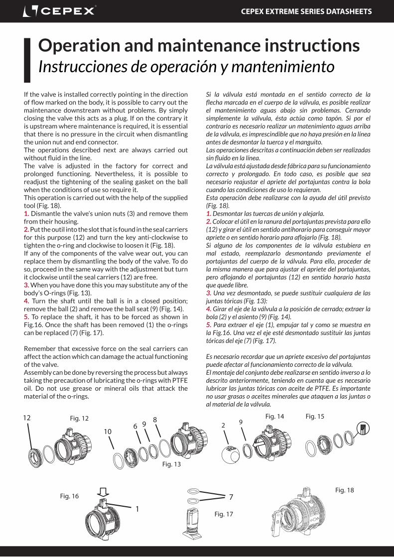
Operation and maintenance instructionsInstrucciones de operación y mantenimiento
If the valve is installed correctly pointing in the direction of flow marked on the body, it is possible to carry out the maintenance downstream without problems. By simply closing the valve this acts as a plug. If on the contrary it is upstream where maintenance is required, it is essential that there is no pressure in the circuit when dismantling the union nut and end connector.The operations described next are always carried out without fluid in the line.The valve is adjusted in the factory for correct and prolonged functioning. Nevertheless, it is possible to readjust the tightening of the sealing gasket on the ball when the conditions of use so require it.This operation is carried out with the help of the supplied tool (Fig. 18).1. Dismantle the valve’s union nuts (3) and remove them from their housing. 2. Put the outil into the slot that is found in the seal carriers for this purpose (12) and turn the key anti-clockwise to tighten the o-ring and clockwise to loosen it (Fig. 18). If any of the components of the valve wear out, you can replace them by dismantling the body of the valve. To do so, proceed in the same way with the adjustment but turn it clockwise until the seal carriers (12) are free. 3. When you have done this you may substitute any of the body’s O-rings (Fig. 13). 4. Turn the shaft until the ball is in a closed position; remove the ball (2) and remove the ball seat (9) (Fig. 14).5. To replace the shaft, it has to be forced as shown in Fig.16. Once the shaft has been removed (1) the o-rings can be replaced (7) (Fig. 17).
Remember that excessive force on the seal carriers can affect the action which can damage the actual functioning of the valve.Assembly can be done by reversing the process but always taking the precaution of lubricating the o-rings with PTFE oil. Do not use grease or mineral oils that attack the material of the o-rings.
Si la válvula está montada en el sentido correcto de la flecha marcada en el cuerpo de la válvula, es posible realizar el mantenimiento aguas abajo sin problemas. Cerrando simplemente la válvula, ésta actúa como tapón. Si por el contrario es necesario realizar un matenimiento aguas arriba de la válvula, es imprescindible que no haya presión en la línea antes de desmontar la tuerca y el manguito.Las operaciones descritas a continuación deben ser realizadas sin fluido en la línea.La válvula está ajustada desde fábrica para su funcionamiento correcto y prolongado. En todo caso, es posible que sea necesario reajustar el apriete del portajuntas contra la bola cuando las condiciones de uso lo requieran.Esta operación debe realizarse con la ayuda del útil previsto (Fig. 18).1. Desmontar las tuercas de unión y alejarla. 2. Colocar el útil en la ranura del portajuntas prevista para ello (12) y girar el útil en sentido antihorario para conseguir mayor apriete o en sentido horario para aflojarlo (Fig. 18). Si alguno de los componentes de la válvula estubiera en mal estado, reemplazarlo desmontando previamente el portajuntas del cuerpo de la válvula. Para ello, proceder de la misma manera que para ajustar el apriete del portajuntas, pero aflojando el portajuntas (12) en sentido horario hasta que quede libre. 3. Una vez desmontado, se puede sustituir cualquiera de las juntas tóricas (Fig. 13): 4. Girar el eje de la válvula a la posición de cerrado; extraer la bola (2) y el asiento (9) (Fig. 14).5. Para extraer el eje (1), empujar tal y como se muestra en la Fig.16. Una vez el eje esté desmontado sustituir las juntas tóricas del eje (7) (Fig. 17).
Es necesario recordar que un apriete excesivo del portajuntas puede afectar al funcionamiento correcto de la válvula.El montaje del conjunto debe realizarse en sentido inverso a lo descrito anteriormente, teniendo en cuenta que es necesario lubricar las juntas tóricas con aceite de PTFE. Es importante no usar grasas o aceites minerales que ataquen a las juntas o al material de la válvula.
CEPEX EXTREME SERIES DATASHEETS
Mount and dismantle the actuatorMontaje y desmontaje del actuador
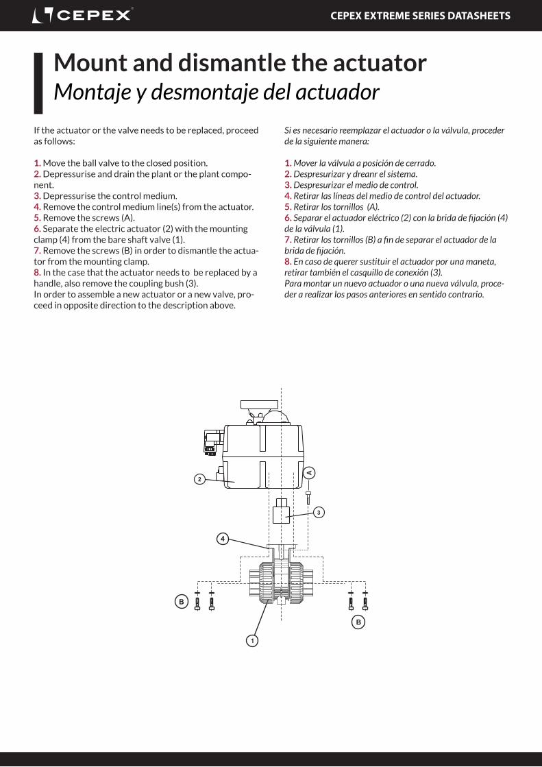
If the actuator or the valve needs to be replaced, proceed as follows:
1. Move the ball valve to the closed position.2. Depressurise and drain the plant or the plant compo-nent.3. Depressurise the control medium.4. Remove the control medium line(s) from the actuator.5. Remove the screws (A).6. Separate the electric actuator (2) with the mounting clamp (4) from the bare shaft valve (1).7. Remove the screws (B) in order to dismantle the actua-tor from the mounting clamp.8. In the case that the actuator needs to be replaced by a handle, also remove the coupling bush (3).In order to assemble a new actuator or a new valve, pro-ceed in opposite direction to the description above.
Si es necesario reemplazar el actuador o la válvula, proceder de la siguiente manera:
1. Mover la válvula a posición de cerrado.2. Despresurizar y dreanr el sistema.3. Despresurizar el medio de control.4. Retirar las líneas del medio de control del actuador.5. Retirar los tornillos (A).6. Separar el actuador eléctrico (2) con la brida de fijación (4) de la válvula (1).7. Retirar los tornillos (B) a fin de separar el actuador de la brida de fijación.8. En caso de querer sustituir el actuador por una maneta, retirar también el casquillo de conexión (3).Para montar un nuevo actuador o una nueva válvula, proce-der a realizar los pasos anteriores en sentido contrario.
CEPEX EXTREME SERIES DATASHEETS
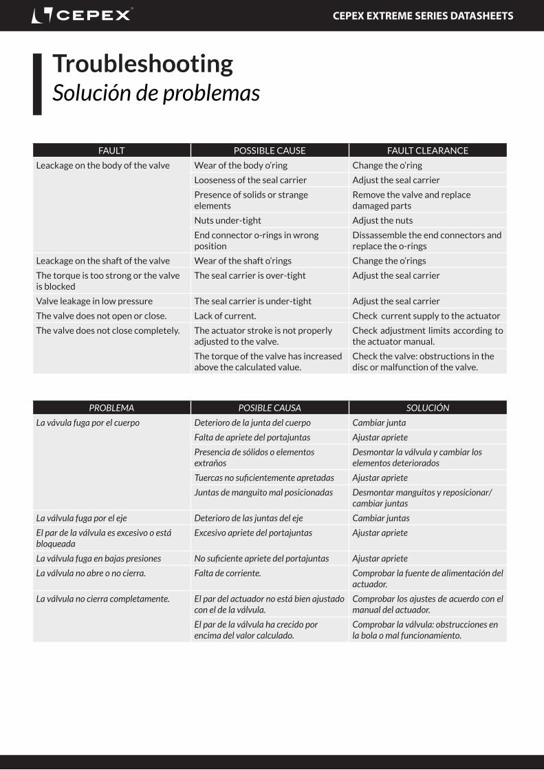
FAULT POSSIBLE CAUSE FAULT CLEARANCE
Leackage on the body of the valve Wear of the body o’ring Change the o’ring
Looseness of the seal carrier Adjust the seal carrier
Presence of solids or strange elements
Remove the valve and replace damaged parts
Nuts under-tight Adjust the nuts
End connector o-rings in wrong position
Dissassemble the end connectors and replace the o-rings
Leackage on the shaft of the valve Wear of the shaft o’rings Change the o’rings
The torque is too strong or the valve is blocked
The seal carrier is over-tight Adjust the seal carrier
Valve leakage in low pressure The seal carrier is under-tight Adjust the seal carrier
The valve does not open or close. Lack of current. Check current supply to the actuator
The valve does not close completely. The actuator stroke is not properly adjusted to the valve.
Check adjustment limits according to the actuator manual.
The torque of the valve has increased above the calculated value.
Check the valve: obstructions in the disc or malfunction of the valve.
PROBLEMA POSIBLE CAUSA SOLUCIÓN
La vávula fuga por el cuerpo Deterioro de la junta del cuerpo Cambiar junta
Falta de apriete del portajuntas Ajustar apriete
Presencia de sólidos o elementos extraños
Desmontar la válvula y cambiar los elementos deteriorados
Tuercas no suficientemente apretadas Ajustar apriete
Juntas de manguito mal posicionadas Desmontar manguitos y reposicionar/cambiar juntas
La válvula fuga por el eje Deterioro de las juntas del eje Cambiar juntas
El par de la válvula es excesivo o está bloqueada
Excesivo apriete del portajuntas Ajustar apriete
La válvula fuga en bajas presiones No suficiente apriete del portajuntas Ajustar apriete
La válvula no abre o no cierra. Falta de corriente. Comprobar la fuente de alimentación del actuador.
La válvula no cierra completamente. El par del actuador no está bien ajustado con el de la válvula.
Comprobar los ajustes de acuerdo con el manual del actuador.
El par de la válvula ha crecido por encima del valor calculado.
Comprobar la válvula: obstrucciones en la bola o mal funcionamiento.
TroubleshootingSolución de problemas
CEPEX EXTREME SERIES DATASHEETS
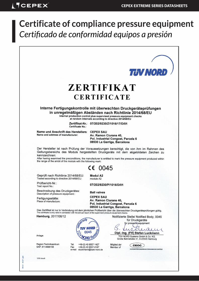
Certificate of compliance pressure equipmentCertificado de conformidad equipos a presión
CEPEX EXTREME SERIES DATASHEETS
Certificate of compliance pressure equipment Optional accessoriesAccesorios opcionales
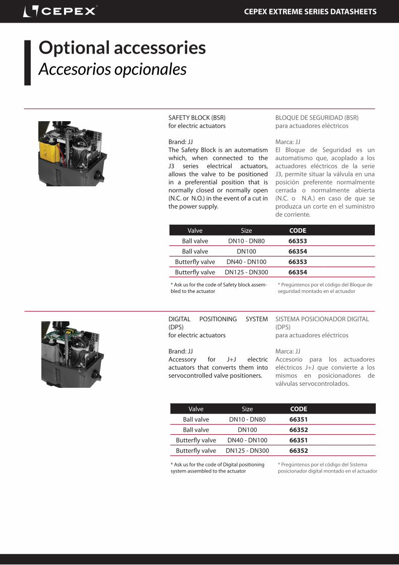
SAFETY BLOCK (BSR)for electric actuators
Brand: JJThe Safety Block is an automatism which, when connected to the J3 series electrical actuators, allows the valve to be positioned in a preferential position that is normally closed or normally open (N.C. or N.O.) in the event of a cut in the power supply.
BLOQUE DE SEGURIDAD (BSR)para actuadores eléctricos
Marca: JJEl Bloque de Seguridad es un automatismo que, acoplado a los actuadores eléctricos de la serie J3, permite situar la válvula en una posición preferente normalmente cerrada o normalmente abierta (N.C. o N.A.) en caso de que se produzca un corte en el suministro de corriente.
DIGITAL POSITIONING SYSTEM (DPS)for electric actuators
Brand: JJAccessory for J+J electric actuators that converts them into servocontrolled valve positioners.
SISTEMA POSICIONADOR DIGITAL (DPS)para actuadores eléctricos
Marca: JJAccesorio para los actuadores eléctricos J+J que convierte a los mismos en posicionadores de válvulas servocontrolados.
Valve Size CODE
Ball valve DN10 - DN80 66353
Ball valve DN100 66354
Butterfly valve DN40 - DN100 66353
Butterfly valve DN125 - DN300 66354
Valve Size CODE
Ball valve DN10 - DN80 66351
Ball valve DN100 66352
Butterfly valve DN40 - DN100 66351
Butterfly valve DN125 - DN300 66352
* Pregúntenos por el código del Bloque de seguridad montado en el actuador
* Ask us for the code of Safety block assem-bled to the actuator
* Pregúntenos por el código del Sistema posicionador digital montado en el actuador
* Ask us for the code of Digital positioning system assembled to the actuator
CEPEX EXTREME SERIES DATASHEETS
AnnexesAnexos
Some interesting links to know more about the company and the product:
· Website
· Company certifications ISO9001 ISO14001
· Company presentation
· Instructions manual
· Commercial brochure
· Hydraulic concepts and installation advice
Algunos links interesantes para conocer más de la empresa y del producto:
· Página web
· Certificados empresa ISO9001 ISO14001
· Presentación de empresa
· Manual de instrucciones
· Folleto comercial
· Conceptos hidráulicos y consejos de insta-lación