
Powerware 9155 Parallel UPS (8-15 kVA) User's Guide - Eaton
66
Powerware 9155 Parallel UPS 8–15 kVA User's Guide ®
Transcript of Powerware 9155 Parallel UPS (8-15 kVA) User's Guide - Eaton
Powerware 9155 Parallel UPS8–15 kVAUser's Guide
®
Class A EMC StatementsFCC Part 15
NOTE This equipment has been tested and found to comply with the limits for a Class A digital device, pursuant to
part 15 of the FCC Rules. These limits are designed to provide reasonable protection against harmful interference
when the equipment is operated in a commercial environment. This equipment generates, uses, and can radiate
radio frequency energy and, if not installed and used in accordance with the instruction manual, may cause harmful
interference to radio communications. Operation of this equipment in a residential area is likely to cause harmful
interference in which case the user will be required to correct the interference at his own expense.
ICES-003
This Class A Interference Causing Equipment meets all requirements of the Canadian Interference Causing
Equipment Regulations ICES‐003.
Cet appareil numérique de la classe A respecte toutes les exigences du Reglement sur le matériel brouilleur du
Canada.
IEC 62040-2
Some configurations are classified under IEC 62040-2 as “Class‐A UPS for Unrestricted Sales Distribution.” For
these configurations, the following applies:
WARNING This is a Class A‐UPS Product. In a domestic environment, this product may cause radio interference, in
which case, the user may be required to take additional measures.
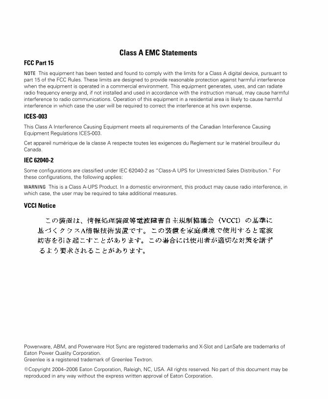
VCCI Notice
Powerware, ABM, and Powerware Hot Sync are registered trademarks and X-Slot and LanSafe are trademarks of
Eaton Power Quality Corporation.
Greenlee is a registered trademark of Greenlee Textron.
�Copyright 2004–2006 Eaton Corporation, Raleigh, NC, USA. All rights reserved. No part of this document may be
reproduced in any way without the express written approval of Eaton Corporation.

Requesting a Declaration of ConformityUnits that are labeled with a CE mark comply with the following harmonized standards and EU directives:
� Harmonized Standards: IEC 62040-1-1 and IEC 62040-2; IEC 60950 Third Edition
� EU Directives: 73/23/EEC, Council Directive on equipment designed for use within certain voltage limits
93/68/EEC, Amending Directive 73/23/EEC
89/336/EEC, Council Directive relating to electromagnetic compatibility
92/31/EEC, Amending Directive 89/336/EEC relating to EMC
The EC Declaration of Conformity is available upon request for products with a CE mark. For copies of the EC
Declaration of Conformity, contact:
Eaton Power Quality Oy
Koskelontie 13
FIN-02920 Espoo
Finland
Phone: +358-9-452 661
Fax: +358-9-452 665 68
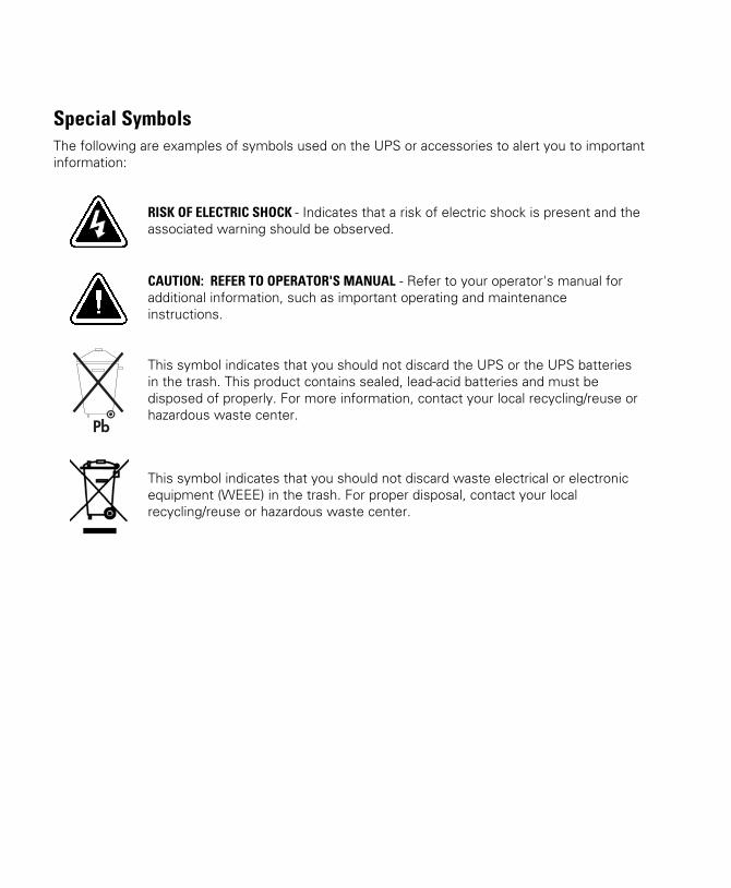
Special SymbolsThe following are examples of symbols used on the UPS or accessories to alert you to important
information:
RISK OF ELECTRIC SHOCK - Indicates that a risk of electric shock is present and the
associated warning should be observed.
CAUTION: REFER TO OPERATOR'S MANUAL - Refer to your operator's manual for
additional information, such as important operating and maintenance
instructions.
This symbol indicates that you should not discard the UPS or the UPS batteries
in the trash. This product contains sealed, lead‐acid batteries and must be
disposed of properly. For more information, contact your local recycling/reuse or
hazardous waste center.
This symbol indicates that you should not discard waste electrical or electronic
equipment (WEEE) in the trash. For proper disposal, contact your local
recycling/reuse or hazardous waste center.
EATON Powerware® 9155 Parallel UPS (8–15 kVA) User's Guide � 164201592 C www.eaton.com/powerquality i
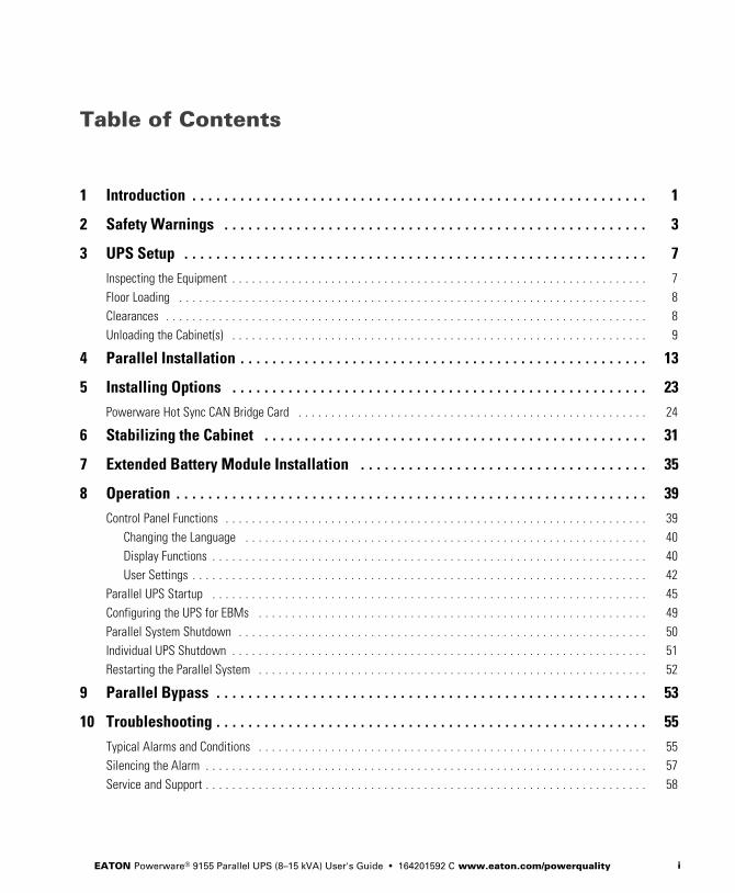
Table of Contents
1 Introduction 1 . . . . . . . . . . . . . . . . . . . . . . . . . . . . . . . . . . . . . . . . . . . . . . . . . . . . . . . . .
2 Safety Warnings 3 . . . . . . . . . . . . . . . . . . . . . . . . . . . . . . . . . . . . . . . . . . . . . . . . . . . . .
3 UPS Setup 7 . . . . . . . . . . . . . . . . . . . . . . . . . . . . . . . . . . . . . . . . . . . . . . . . . . . . . . . . . .
Inspecting the Equipment 7 . . . . . . . . . . . . . . . . . . . . . . . . . . . . . . . . . . . . . . . . . . . . . . . . . . . . . . . . . . . . . . .
Floor Loading 8 . . . . . . . . . . . . . . . . . . . . . . . . . . . . . . . . . . . . . . . . . . . . . . . . . . . . . . . . . . . . . . . . . . . . . . .
Clearances 8 . . . . . . . . . . . . . . . . . . . . . . . . . . . . . . . . . . . . . . . . . . . . . . . . . . . . . . . . . . . . . . . . . . . . . . . . .
Unloading the Cabinet(s) 9 . . . . . . . . . . . . . . . . . . . . . . . . . . . . . . . . . . . . . . . . . . . . . . . . . . . . . . . . . . . . . . .
4 Parallel Installation 13 . . . . . . . . . . . . . . . . . . . . . . . . . . . . . . . . . . . . . . . . . . . . . . . . . . .
5 Installing Options 23 . . . . . . . . . . . . . . . . . . . . . . . . . . . . . . . . . . . . . . . . . . . . . . . . . . . .
Powerware Hot Sync CAN Bridge Card 24 . . . . . . . . . . . . . . . . . . . . . . . . . . . . . . . . . . . . . . . . . . . . . . . . . . . . .
6 Stabilizing the Cabinet 31 . . . . . . . . . . . . . . . . . . . . . . . . . . . . . . . . . . . . . . . . . . . . . . . .
7 Extended Battery Module Installation 35 . . . . . . . . . . . . . . . . . . . . . . . . . . . . . . . . . . . .
8 Operation 39 . . . . . . . . . . . . . . . . . . . . . . . . . . . . . . . . . . . . . . . . . . . . . . . . . . . . . . . . . . .
Control Panel Functions 39 . . . . . . . . . . . . . . . . . . . . . . . . . . . . . . . . . . . . . . . . . . . . . . . . . . . . . . . . . . . . . . . .
Changing the Language 40 . . . . . . . . . . . . . . . . . . . . . . . . . . . . . . . . . . . . . . . . . . . . . . . . . . . . . . . . . . . . .
Display Functions 40 . . . . . . . . . . . . . . . . . . . . . . . . . . . . . . . . . . . . . . . . . . . . . . . . . . . . . . . . . . . . . . . . . .
User Settings 42 . . . . . . . . . . . . . . . . . . . . . . . . . . . . . . . . . . . . . . . . . . . . . . . . . . . . . . . . . . . . . . . . . . . . .
Parallel UPS Startup 45 . . . . . . . . . . . . . . . . . . . . . . . . . . . . . . . . . . . . . . . . . . . . . . . . . . . . . . . . . . . . . . . . . .
Configuring the UPS for EBMs 49 . . . . . . . . . . . . . . . . . . . . . . . . . . . . . . . . . . . . . . . . . . . . . . . . . . . . . . . . . . .
Parallel System Shutdown 50 . . . . . . . . . . . . . . . . . . . . . . . . . . . . . . . . . . . . . . . . . . . . . . . . . . . . . . . . . . . . . .
Individual UPS Shutdown 51 . . . . . . . . . . . . . . . . . . . . . . . . . . . . . . . . . . . . . . . . . . . . . . . . . . . . . . . . . . . . . . .
Restarting the Parallel System 52 . . . . . . . . . . . . . . . . . . . . . . . . . . . . . . . . . . . . . . . . . . . . . . . . . . . . . . . . . . .
9 Parallel Bypass 53 . . . . . . . . . . . . . . . . . . . . . . . . . . . . . . . . . . . . . . . . . . . . . . . . . . . . . .
10 Troubleshooting 55 . . . . . . . . . . . . . . . . . . . . . . . . . . . . . . . . . . . . . . . . . . . . . . . . . . . . . .
Typical Alarms and Conditions 55 . . . . . . . . . . . . . . . . . . . . . . . . . . . . . . . . . . . . . . . . . . . . . . . . . . . . . . . . . . .
Silencing the Alarm 57 . . . . . . . . . . . . . . . . . . . . . . . . . . . . . . . . . . . . . . . . . . . . . . . . . . . . . . . . . . . . . . . . . . .
Service and Support 58 . . . . . . . . . . . . . . . . . . . . . . . . . . . . . . . . . . . . . . . . . . . . . . . . . . . . . . . . . . . . . . . . . . .

TABLE OF CONTENTS
EATON Powerware® 9155 Parallel UPS (8–15 kVA) User's Guide � 164201592 C www.eaton.com/powerqualityii
EATON Powerware® 9155 Parallel UPS (8–15 kVA) User's Guide � 164201592 C www.eaton.com/powerquality 1
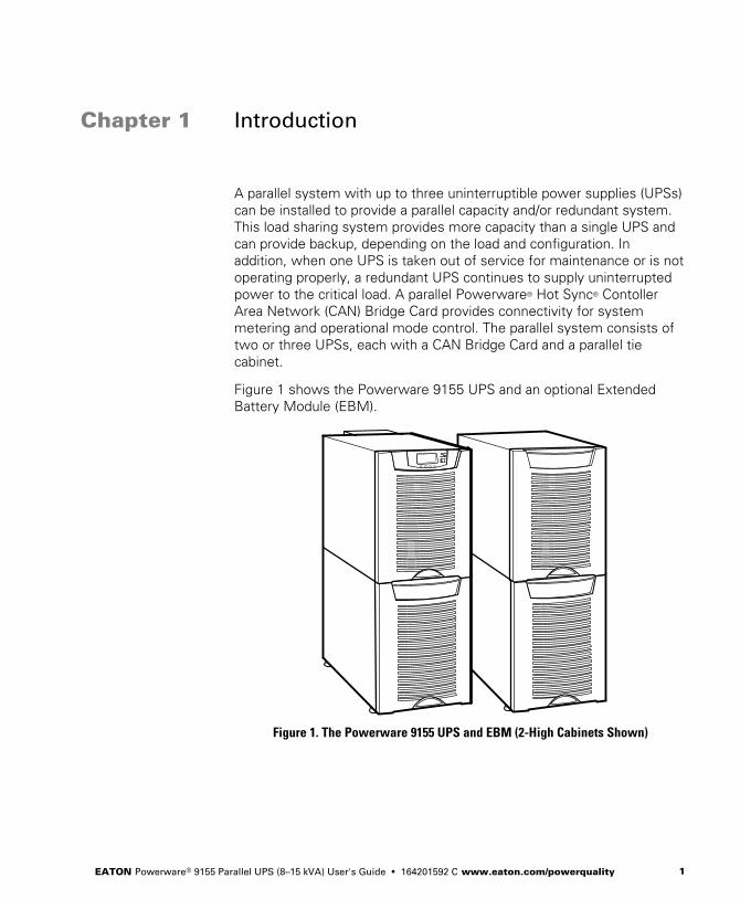
Chapter 1 Introduction
A parallel system with up to three uninterruptible power supplies (UPSs)
can be installed to provide a parallel capacity and/or redundant system.
This load sharing system provides more capacity than a single UPS and
can provide backup, depending on the load and configuration. In
addition, when one UPS is taken out of service for maintenance or is not
operating properly, a redundant UPS continues to supply uninterrupted
power to the critical load. A parallel Powerware® Hot Sync® Contoller
Area Network (CAN) Bridge Card provides connectivity for system
metering and operational mode control. The parallel system consists of
two or three UPSs, each with a CAN Bridge Card and a parallel tie
cabinet.
Figure 1 shows the Powerware 9155 UPS and an optional Extended
Battery Module (EBM).
Figure 1. The Powerware 9155 UPS and EBM (2-High Cabinets Shown)

INTRODUCTION
EATON Powerware® 9155 Parallel UPS (8–15 kVA) User's Guide � 164201592 C www.eaton.com/powerquality2
EATON Powerware® 9155 Parallel UPS (8–15 kVA) User's Guide � 164201592 C www.eaton.com/powerquality 3
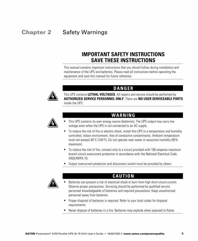
Chapter 2 Safety Warnings
IMPORTANT SAFETY INSTRUCTIONSSAVE THESE INSTRUCTIONS
This manual contains important instructions that you should follow during installation andmaintenance of the UPS and batteries. Please read all instructions before operating theequipment and save this manual for future reference.
D A N G E RThis UPS contains LETHAL VOLTAGES. All repairs and service should be performed byAUTHORIZED SERVICE PERSONNEL ONLY. There are NO USER SERVICEABLE PARTSinside the UPS.
W A R N I N G� This UPS contains its own energy source (batteries). The UPS output may carry live
voltage even when the UPS is not connected to an AC supply.
� To reduce the risk of fire or electric shock, install this UPS in a temperature and humiditycontrolled, indoor environment, free of conductive contaminants. Ambient temperaturemust not exceed 40°C (104°F). Do not operate near water or excessive humidity (95%maximum).
� To reduce the risk of fire, connect only to a circuit provided with 100 amperes maximumbranch circuit overcurrent protection in accordance with the National Electrical Code,ANSI/NFPA 70.
� Output overcurrent protection and disconnect switch must be provided by others.
C A U T I O N� Batteries can present a risk of electrical shock or burn from high short circuit current.
Observe proper precautions. Servicing should be performed by qualified servicepersonnel knowledgeable of batteries and required precautions. Keep unauthorizedpersonnel away from batteries.
� Proper disposal of batteries is required. Refer to your local codes for disposalrequirements.
� Never dispose of batteries in a fire. Batteries may explode when exposed to flame.
SAFETY WARNINGS
EATON Powerware® 9155 Parallel UPS (8–15 kVA) User's Guide � 164201592 C www.eaton.com/powerquality4
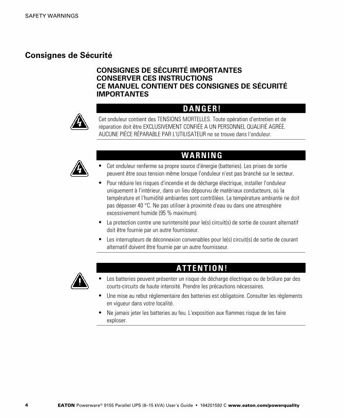
Consignes de Sécurité
CONSIGNES DE SÉCURITÉ IMPORTANTESCONSERVER CES INSTRUCTIONSCE MANUEL CONTIENT DES CONSIGNES DE SÉCURITÉIMPORTANTES
D A N G E R !Cet onduleur contient des TENSIONS MORTELLES. Toute opération d'entretien et deréparation doit être EXCLUSIVEMENT CONFIÉE A UN PERSONNEL QUALIFIÉ AGRÉÉ.AUCUNE PIÈCE RÉPARABLE PAR L'UTILISATEUR ne se trouve dans l'onduleur.
W A R N I N G� Cet onduleur renferme sa propre source d'énergie (batteries). Les prises de sortie
peuvent être sous tension même lorsque l'onduleur n'est pas branché sur le secteur.
� Pour réduire les risques d'incendie et de décharge électrique, installer l'onduleuruniquement à l'intérieur, dans un lieu dépourvu de matériaux conducteurs, où latempérature et l'humidité ambiantes sont contrôlées. La température ambiante ne doitpas dépasser 40 °C. Ne pas utiliser à proximité d'eau ou dans une atmosphèreexcessivement humide (95 % maximum).
� La protection contre une surintensité pour le(s) circuit(s) de sortie de courant alternatifdoit être fournie par un autre fournisseur.
� Les interrupteurs de déconnexion convenables pour le(s) circuit(s) de sortie de courantalternatif doivent être fournie par un autre fournisseur.
A T T E N T I O N !� Les batteries peuvent présenter un risque de décharge électrique ou de brûlure par des
courts-circuits de haute intensité. Prendre les précautions nécessaires.
� Une mise au rebut réglementaire des batteries est obligatoire. Consulter les règlementsen vigueur dans votre localité.
� Ne jamais jeter les batteries au feu. L'exposition aux flammes risque de les faireexploser.
SAFETY WARNINGS
EATON Powerware® 9155 Parallel UPS (8–15 kVA) User's Guide � 164201592 C www.eaton.com/powerquality 5
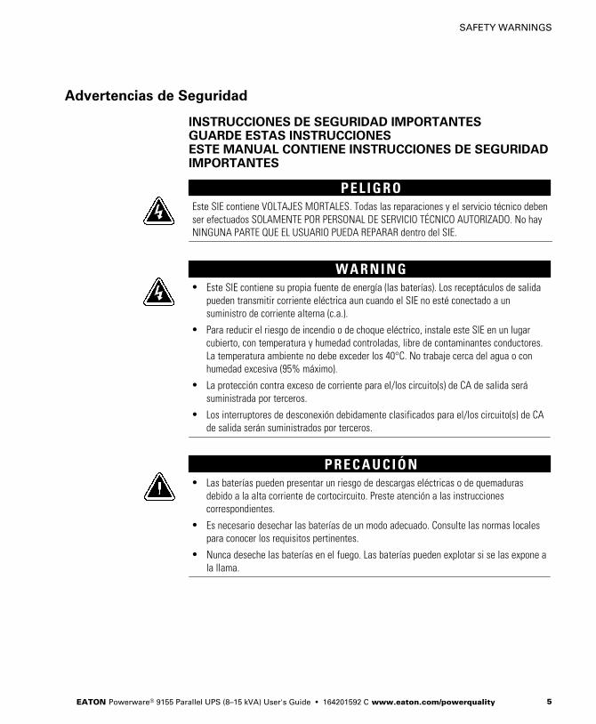
Advertencias de Seguridad
INSTRUCCIONES DE SEGURIDAD IMPORTANTESGUARDE ESTAS INSTRUCCIONESESTE MANUAL CONTIENE INSTRUCCIONES DE SEGURIDADIMPORTANTES
P E L I G R OEste SIE contiene VOLTAJES MORTALES. Todas las reparaciones y el servicio técnico debenser efectuados SOLAMENTE POR PERSONAL DE SERVICIO TÉCNICO AUTORIZADO. No hayNINGUNA PARTE QUE EL USUARIO PUEDA REPARAR dentro del SIE.
W A R N I N G� Este SIE contiene su propia fuente de energía (las baterías). Los receptáculos de salida
pueden transmitir corriente eléctrica aun cuando el SIE no esté conectado a unsuministro de corriente alterna (c.a.).
� Para reducir el riesgo de incendio o de choque eléctrico, instale este SIE en un lugarcubierto, con temperatura y humedad controladas, libre de contaminantes conductores.La temperatura ambiente no debe exceder los 40°C. No trabaje cerca del agua o conhumedad excesiva (95% máximo).
� La protección contra exceso de corriente para el/los circuito(s) de CA de salida serásuministrada por terceros.
� Los interruptores de desconexión debidamente clasificados para el/los circuito(s) de CAde salida serán suministrados por terceros.
P R E C A U C I Ó N� Las baterías pueden presentar un riesgo de descargas eléctricas o de quemaduras
debido a la alta corriente de cortocircuito. Preste atención a las instruccionescorrespondientes.
� Es necesario desechar las baterías de un modo adecuado. Consulte las normas localespara conocer los requisitos pertinentes.
� Nunca deseche las baterías en el fuego. Las baterías pueden explotar si se las expone ala llama.

SAFETY WARNINGS
EATON Powerware® 9155 Parallel UPS (8–15 kVA) User's Guide � 164201592 C www.eaton.com/powerquality6
EATON Powerware® 9155 Parallel UPS (8–15 kVA) User's Guide � 164201592 C www.eaton.com/powerquality 7
Chapter 3 UPS Setup
This chapter describes:
� Equipment inspection
� Floor loading and clearances
� Unloading the cabinet(s)
The instructions are intended for the chief operator/system supervisor,
electrical consultants, and installation electricians. Local regulations and
electrical code must be followed during the UPS installation.
Inspecting the Equipment
If any equipment has been damaged during shipment, keep the shipping
and packing materials for the carrier or place of purchase and file a claim
for shipping damage. If you discover damage after acceptance, file a
claim for concealed damage.
To file a claim for shipping damage or concealed damage: 1) File with
the carrier within 15 days of receipt of the equipment; 2) Send a copy of
the damage claim within 15 days to your service representative.
NOTE Check the battery recharge date on the packaging label. If the date has expired and
the batteries were never recharged, do not use the UPS. Contact your service representative.
UPS SETUP
EATON Powerware® 9155 Parallel UPS (8–15 kVA) User's Guide � 164201592 C www.eaton.com/powerquality8
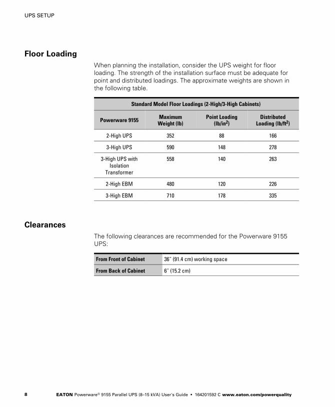
Floor Loading
When planning the installation, consider the UPS weight for floor
loading. The strength of the installation surface must be adequate for
point and distributed loadings. The approximate weights are shown in
the following table.
Standard Model Floor Loadings (2-High/3-High Cabinets)
Powerware 9155 MaximumWeight (lb)
Point Loading(lb/in2)
DistributedLoading (lb/ft2)
2-High UPS 352 88 166
3-High UPS 590 148 278
3-High UPS with
Isolation
Transformer
558 140 263
2-High EBM 480 120 226
3-High EBM 710 178 335
Clearances
The following clearances are recommended for the Powerware 9155
UPS:
From Front of Cabinet 36” (91.4 cm) working space
From Back of Cabinet 6” (15.2 cm)
UPS SETUP
EATON Powerware® 9155 Parallel UPS (8–15 kVA) User's Guide � 164201592 C www.eaton.com/powerquality 9
Unloading the Cabinet(s)
The following tools are required for unloading the cabinet(s):
� 15 mm wrench or socket
� 7 mm nutdriver or socket
C A U T I O NThe UPS and Extended Battery Module (EBM) are heavy (see page 8). Unloading the cabinetsrequires at least two people to safely remove the cabinets from the pallet.
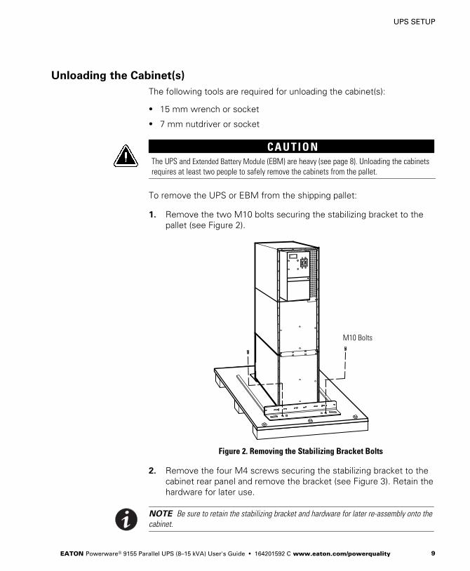
To remove the UPS or EBM from the shipping pallet:
1. Remove the two M10 bolts securing the stabilizing bracket to the
pallet (see Figure 2).
M10 Bolts
Figure 2. Removing the Stabilizing Bracket Bolts
2. Remove the four M4 screws securing the stabilizing bracket to the
cabinet rear panel and remove the bracket (see Figure 3). Retain the
hardware for later use.
NOTE Be sure to retain the stabilizing bracket and hardware for later re-assembly onto the
cabinet.
UPS SETUP
EATON Powerware® 9155 Parallel UPS (8–15 kVA) User's Guide � 164201592 C www.eaton.com/powerquality10
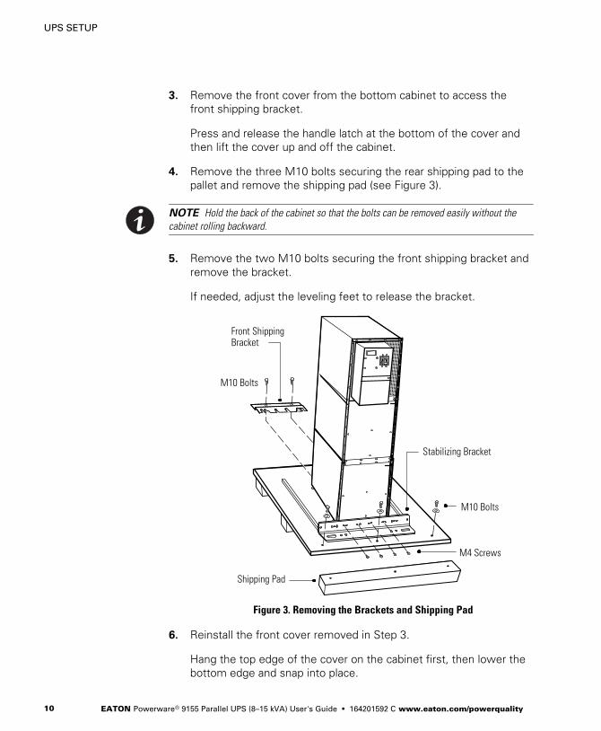
3. Remove the front cover from the bottom cabinet to access the
front shipping bracket.
Press and release the handle latch at the bottom of the cover and
then lift the cover up and off the cabinet.
4. Remove the three M10 bolts securing the rear shipping pad to the
pallet and remove the shipping pad (see Figure 3).
NOTE Hold the back of the cabinet so that the bolts can be removed easily without the
cabinet rolling backward.
5. Remove the two M10 bolts securing the front shipping bracket and
remove the bracket.
If needed, adjust the leveling feet to release the bracket.
Stabilizing Bracket
Front ShippingBracket
Shipping Pad
M4 Screws
M10 Bolts
M10 Bolts
Figure 3. Removing the Brackets and Shipping Pad
6. Reinstall the front cover removed in Step 3.
Hang the top edge of the cover on the cabinet first, then lower the
bottom edge and snap into place.
UPS SETUP
EATON Powerware® 9155 Parallel UPS (8–15 kVA) User's Guide � 164201592 C www.eaton.com/powerquality 11
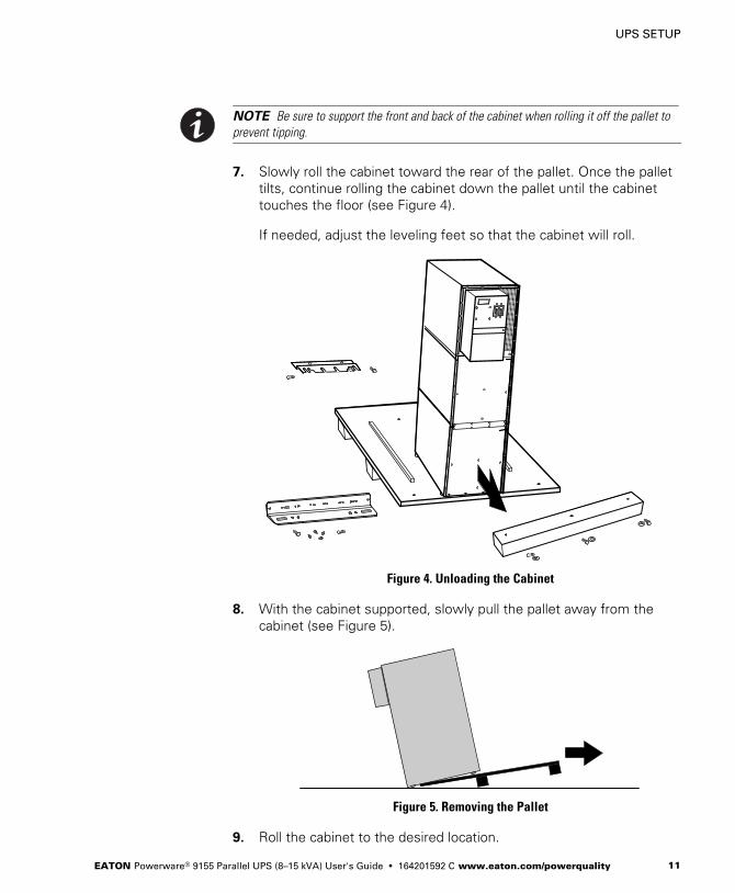
NOTE Be sure to support the front and back of the cabinet when rolling it off the pallet to
prevent tipping.
7. Slowly roll the cabinet toward the rear of the pallet. Once the pallet
tilts, continue rolling the cabinet down the pallet until the cabinet
touches the floor (see Figure 4).
If needed, adjust the leveling feet so that the cabinet will roll.
Figure 4. Unloading the Cabinet
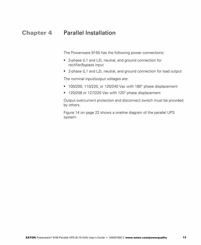
8. With the cabinet supported, slowly pull the pallet away from the
cabinet (see Figure 5).
Figure 5. Removing the Pallet
9. Roll the cabinet to the desired location.

UPS SETUP
EATON Powerware® 9155 Parallel UPS (8–15 kVA) User's Guide � 164201592 C www.eaton.com/powerquality12
EATON Powerware® 9155 Parallel UPS (8–15 kVA) User's Guide � 164201592 C www.eaton.com/powerquality 13
Chapter 4 Parallel Installation
The Powerware 9155 has the following power connections:
� 2‐phase (L1 and L2), neutral, and ground connection for
rectifier/bypass input
� 2‐phase (L1 and L2), neutral, and ground connection for load output
The nominal input/output voltages are:
� 100/200, 110/220, or 120/240 Vac with 180° phase displacement
� 120/208 or 127/220 Vac with 120° phase displacement
Output overcurrent protection and disconnect switch must be provided
by others.
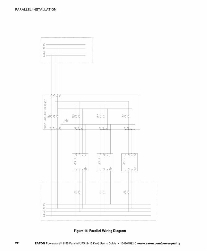
Figure 14 on page 22 shows a oneline diagram of the parallel UPS
system.
PARALLEL INSTALLATION
EATON Powerware® 9155 Parallel UPS (8–15 kVA) User's Guide � 164201592 C www.eaton.com/powerquality14
W A R N I N GOnly qualified service personnel (such as a licensed electrician) should perform the UPSinstallation and initial startup. Risk of electrical shock.
To hardwire the parallel system:
1. Verify that the electrical connections to the installation site have
been properly installed.
2. A wall-mounted, user‐supplied, readily‐accessible disconnection
device must be incorporated in the input wiring.
Compare the circuit breaker ratings and wire sizes to the ones in
the following wiring table:
Table 1. Circuit Breaker Ratings
UPS Capacity Input Circuit Breaker Rating Minimum Wire Size*
8 kVA 60A 4 AWG (21.2 mm2)
10 kVA 80A 3 AWG (26.7 mm2)
12 kVA 100A 2 AWG (33.6 mm2)
15 kVA 100A 2 AWG (33.6 mm2)
*Use only 75°C-rated copper wire. Minimum wire size is based on 120/208 full load
ratings applied to NEC Code Table 310‐16. Code may require a larger AWG size than
shown in this table because of temperature, number of conductors in the conduit, or
long service runs. Follow local requirements.
NOTE To accommodate the feature of easy system expandability, it is recommended that
initial installation of the Powerware 9155 UPS contain wiring to support the maximum
capacity of the UPS cabinet.
3. Switch off utility power to the distribution point where the parallel
tie cabinet and UPSs will be connected. Be absolutely sure there is
no power.
4. Determine your equipment's grounding requirements according to
your local electrical code.
PARALLEL INSTALLATION
EATON Powerware® 9155 Parallel UPS (8–15 kVA) User's Guide � 164201592 C www.eaton.com/powerquality 15
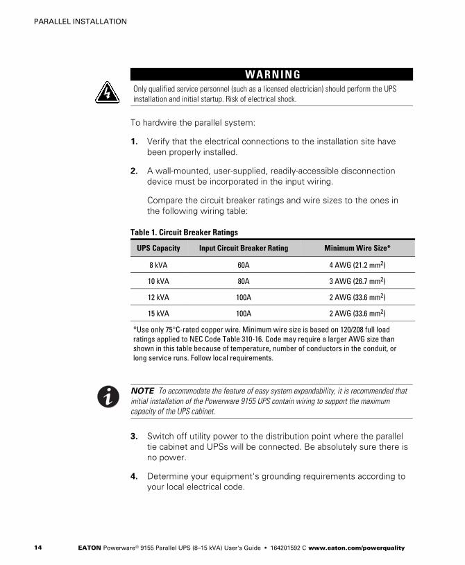
5. Remove the parallel tie cabinet front cover (see Figure 6).
Parallel Cabinet
Figure 6. Parallel Tie Cabinet Front Cover
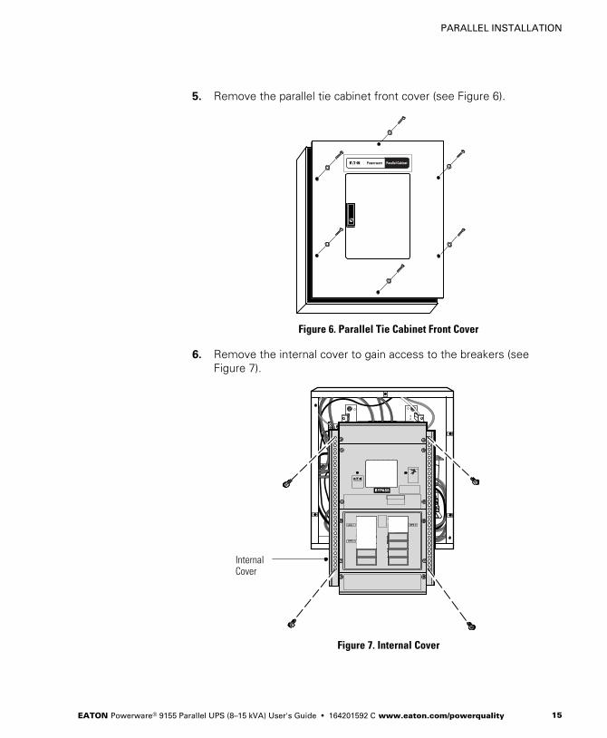
6. Remove the internal cover to gain access to the breakers (see
Figure 7).
InternalCover
Figure 7. Internal Cover

PARALLEL INSTALLATION
EATON Powerware® 9155 Parallel UPS (8–15 kVA) User's Guide � 164201592 C www.eaton.com/powerquality16
7. Punch holes for the conduit (AC input, each UPS output, and load
connection) using a Greenlee® punch or similar device.
8. Verify that the parallel bypass breaker is in the OFF position (see
Figure 8).
9. Mount the parallel tie cabinet to the wall and install the conduit.
Figure 8. Parallel Bypass Breaker
PARALLEL INSTALLATION
EATON Powerware® 9155 Parallel UPS (8–15 kVA) User's Guide � 164201592 C www.eaton.com/powerquality 17
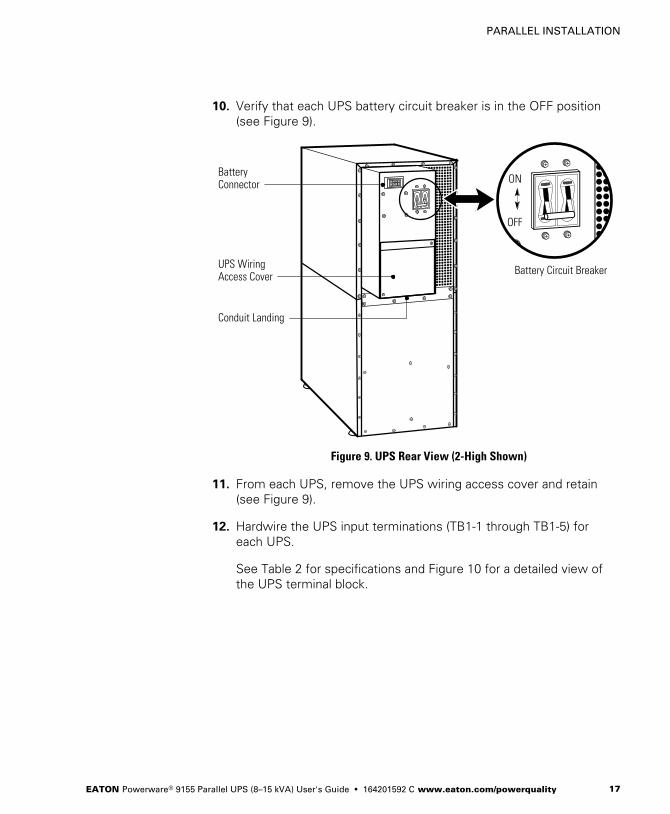
10. Verify that each UPS battery circuit breaker is in the OFF position
(see Figure 9).
ON
OFF
UPS WiringAccess Cover
Conduit Landing
BatteryConnector
Battery Circuit Breaker
Figure 9. UPS Rear View (2-High Shown)
11. From each UPS, remove the UPS wiring access cover and retain
(see Figure 9).
12. Hardwire the UPS input terminations (TB1‐1 through TB1‐5) for
each UPS.
See Table 2 for specifications and Figure 10 for a detailed view of
the UPS terminal block.

PARALLEL INSTALLATION
EATON Powerware® 9155 Parallel UPS (8–15 kVA) User's Guide � 164201592 C www.eaton.com/powerquality18
NOTE Input neutral must be wired for proper operation. Failure to connect an input neutral
will void the warranty.
Table 2. UPS Terminal Block Wiring
Wire Function TerminalPosition
UpstreamCircuit Breaker
MinimumWire Size*
TighteningTorque
Conduit Connection(Entry Size)
Input Ground TB1‐1 8 AWG
25 lb in
(2.83 Nm)
2” access hole for
1‐1/2” conduit
L1 TB1‐3 100A 3 AWG
Neutral TB1‐4 3 AWG
L2 TB1‐5 100A 3 AWG
Output L1 TB1‐6 3 AWG
25 lb in
(2.83 Nm)
2” access hole for
1‐1/2” conduit
Neutral TB1‐7 3 AWG
L2 TB1‐8 3 AWG
Ground TB1‐9 8 AWG
*Use only 75°C-rated copper wire. Minimum wire size is based on 120/208 full load ratings applied to NEC Code
Table 310‐16.
12
3 4 5 6 7 8 9
Input Output
TB1
Figure 10. UPS Terminal Block
PARALLEL INSTALLATION
EATON Powerware® 9155 Parallel UPS (8–15 kVA) User's Guide � 164201592 C www.eaton.com/powerquality 19
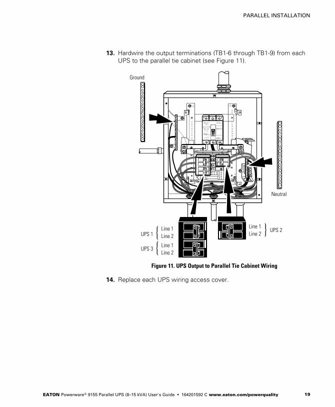
13. Hardwire the output terminations (TB1‐6 through TB1‐9) from each
UPS to the parallel tie cabinet (see Figure 11).
UPS 1UPS 2
UPS 3
Neutral
Line 1Line 2
Line 1Line 2
Line 1Line 2
Ground
Figure 11. UPS Output to Parallel Tie Cabinet Wiring
14. Replace each UPS wiring access cover.
PARALLEL INSTALLATION
EATON Powerware® 9155 Parallel UPS (8–15 kVA) User's Guide � 164201592 C www.eaton.com/powerquality20
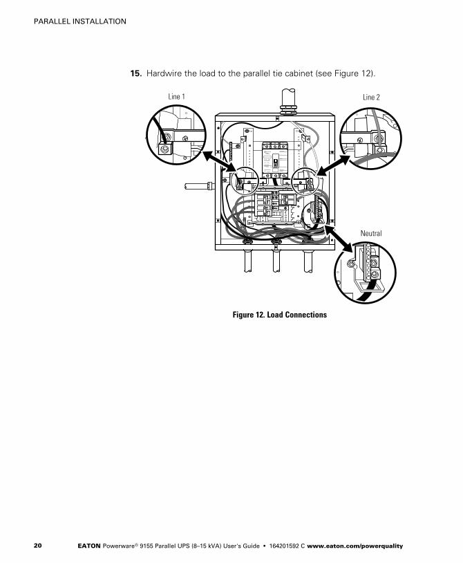
15. Hardwire the load to the parallel tie cabinet (see Figure 12).
Line 1 Line 2
Neutral
Figure 12. Load Connections
PARALLEL INSTALLATION
EATON Powerware® 9155 Parallel UPS (8–15 kVA) User's Guide � 164201592 C www.eaton.com/powerquality 21
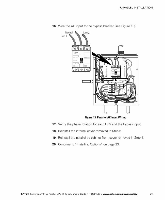
16. Wire the AC input to the bypass breaker (see Figure 13).
Line 1Neutral Line 2
Figure 13. Parallel AC Input Wiring
17. Verify the phase rotation for each UPS and the bypass input.
18. Reinstall the internal cover removed in Step 6.
19. Reinstall the parallel tie cabinet front cover removed in Step 5.
20. Continue to “Installing Options” on page 23.
PARALLEL INSTALLATION
EATON Powerware® 9155 Parallel UPS (8–15 kVA) User's Guide � 164201592 C www.eaton.com/powerquality22
Figure 14. Parallel Wiring Diagram
EATON Powerware® 9155 Parallel UPS (8–15 kVA) User's Guide � 164201592 C www.eaton.com/powerquality 23
Chapter 5 Installing Options
This section describes the Powerware Hot Sync CAN Bridge Card.
For other options, such as additional X-Slot� cards, Powerware
LanSafe� Power Management Software, remote emergency power-off
(REPO), relay output contacts, or programmable signal inputs, refer to
the Powerware 9155 UPS (8–15 kVA) User's Guide.
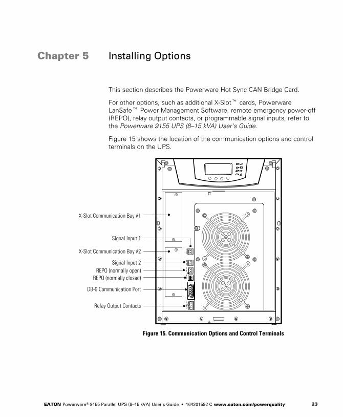
Figure 15 shows the location of the communication options and control
terminals on the UPS.
12
1212
12
123
DB-9 Communication Port
REPO (normally closed)REPO (normally open)
Signal Input 2
Signal Input 1
X-Slot Communication Bay #2
X-Slot Communication Bay #1
Relay Output Contacts
Figure 15. Communication Options and Control Terminals
INSTALLING OPTIONS
EATON Powerware® 9155 Parallel UPS (8–15 kVA) User's Guide � 164201592 C www.eaton.com/powerquality24
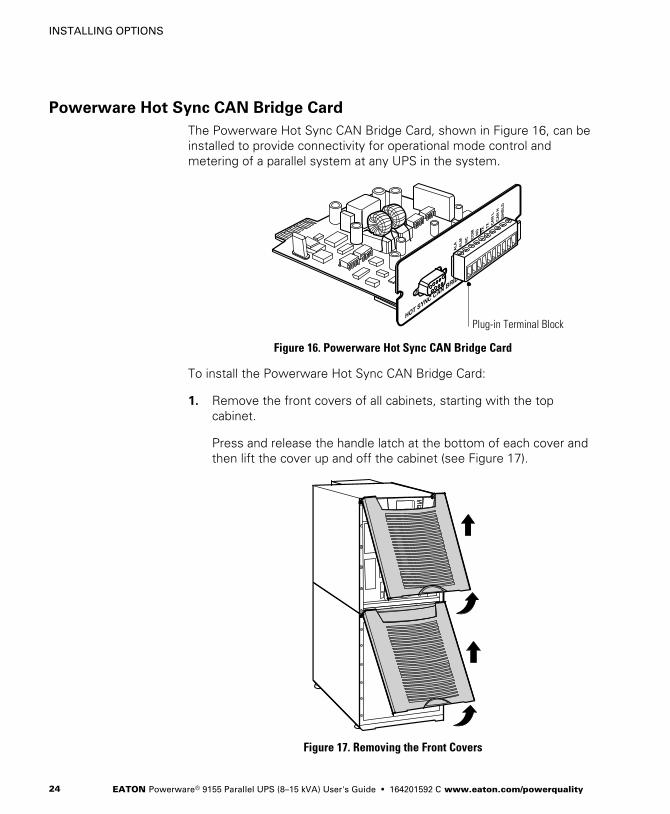
Powerware Hot Sync CAN Bridge Card
The Powerware Hot Sync CAN Bridge Card, shown in Figure 16, can be
installed to provide connectivity for operational mode control and
metering of a parallel system at any UPS in the system.
Plug-in Terminal Block
Figure 16. Powerware Hot Sync CAN Bridge Card
To install the Powerware Hot Sync CAN Bridge Card:
1. Remove the front covers of all cabinets, starting with the top
cabinet.
Press and release the handle latch at the bottom of each cover and
then lift the cover up and off the cabinet (see Figure 17).
Figure 17. Removing the Front Covers
INSTALLING OPTIONS
EATON Powerware® 9155 Parallel UPS (8–15 kVA) User's Guide � 164201592 C www.eaton.com/powerquality 25
2. If you ordered a factory-configured parallel UPS, remove the
Powerware Hot Sync CAN Bridge Card from the X-Slot on the front
of the UPS. Retain the screws.
Otherwise, remove the X-Slot communication bay cover and retain
the screws.
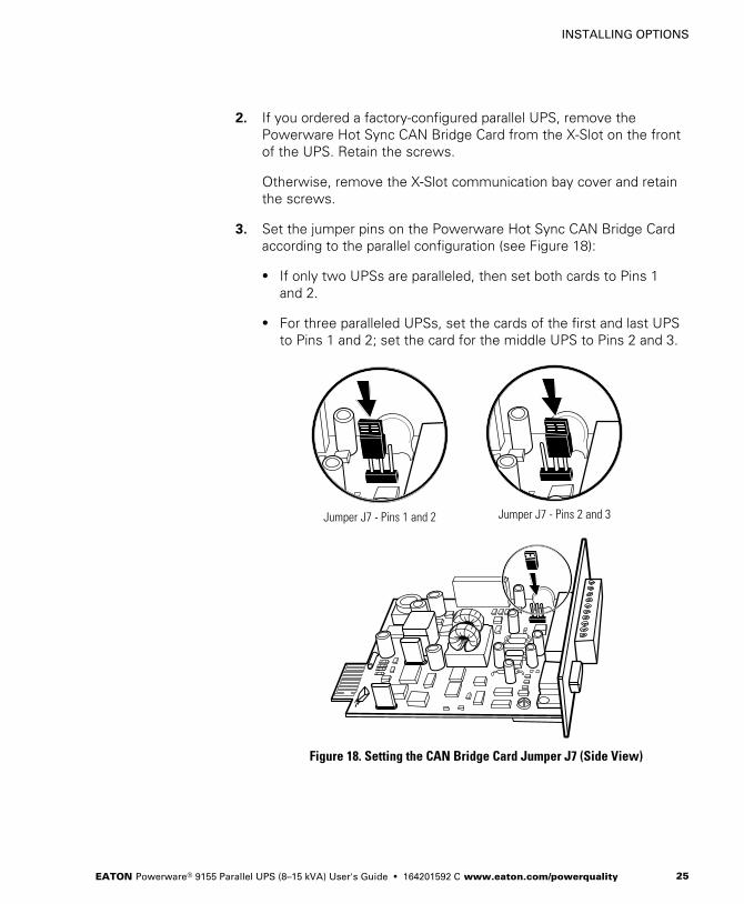
3. Set the jumper pins on the Powerware Hot Sync CAN Bridge Card
according to the parallel configuration (see Figure 18):
� If only two UPSs are paralleled, then set both cards to Pins 1
and 2.
� For three paralleled UPSs, set the cards of the first and last UPS
to Pins 1 and 2; set the card for the middle UPS to Pins 2 and 3.
Jumper J7 - Pins 1 and 2 Jumper J7 - Pins 2 and 3
Figure 18. Setting the CAN Bridge Card Jumper J7 (Side View)
INSTALLING OPTIONS
EATON Powerware® 9155 Parallel UPS (8–15 kVA) User's Guide � 164201592 C www.eaton.com/powerquality26
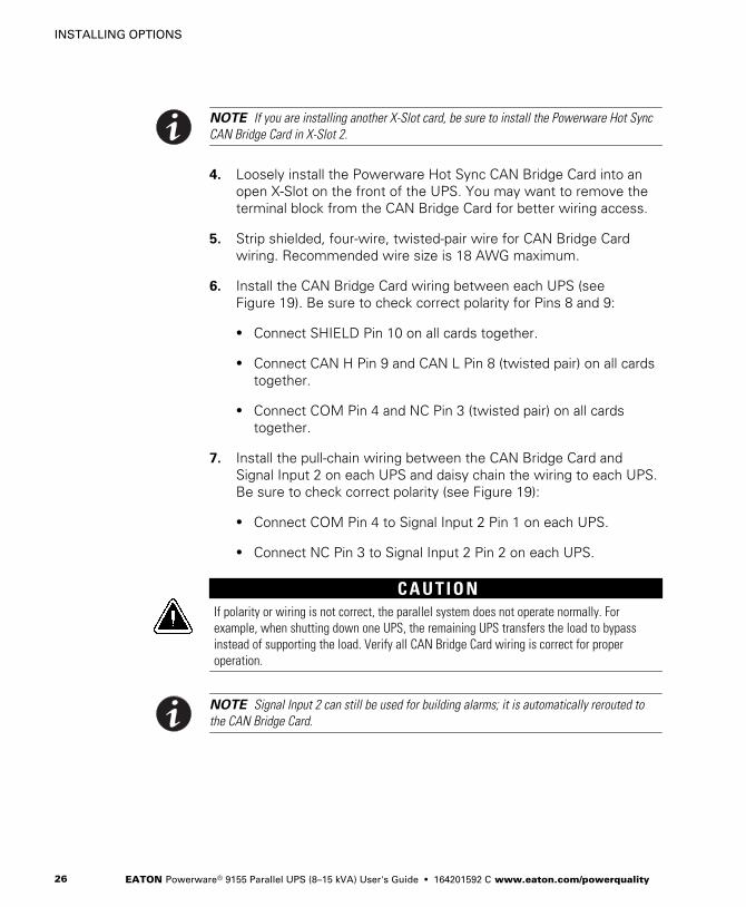
NOTE If you are installing another X-Slot card, be sure to install the Powerware Hot Sync
CAN Bridge Card in X-Slot 2.
4. Loosely install the Powerware Hot Sync CAN Bridge Card into an
open X-Slot on the front of the UPS. You may want to remove the
terminal block from the CAN Bridge Card for better wiring access.
5. Strip shielded, four-wire, twisted-pair wire for CAN Bridge Card
wiring. Recommended wire size is 18 AWG maximum.
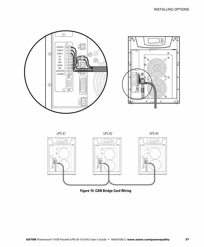
6. Install the CAN Bridge Card wiring between each UPS (see
Figure 19). Be sure to check correct polarity for Pins 8 and 9:
� Connect SHIELD Pin 10 on all cards together.
� Connect CAN H Pin 9 and CAN L Pin 8 (twisted pair) on all cards
together.
� Connect COM Pin 4 and NC Pin 3 (twisted pair) on all cards
together.
7. Install the pull-chain wiring between the CAN Bridge Card and
Signal Input 2 on each UPS and daisy chain the wiring to each UPS.
Be sure to check correct polarity (see Figure 19):
� Connect COM Pin 4 to Signal Input 2 Pin 1 on each UPS.
� Connect NC Pin 3 to Signal Input 2 Pin 2 on each UPS.
C A U T I O NIf polarity or wiring is not correct, the parallel system does not operate normally. Forexample, when shutting down one UPS, the remaining UPS transfers the load to bypassinstead of supporting the load. Verify all CAN Bridge Card wiring is correct for properoperation.
NOTE Signal Input 2 can still be used for building alarms; it is automatically rerouted to
the CAN Bridge Card.
INSTALLING OPTIONS
EATON Powerware® 9155 Parallel UPS (8–15 kVA) User's Guide � 164201592 C www.eaton.com/powerquality 27
UPS #1 UPS #2 UPS #3
Figure 19. CAN Bridge Card Wiring
INSTALLING OPTIONS
EATON Powerware® 9155 Parallel UPS (8–15 kVA) User's Guide � 164201592 C www.eaton.com/powerquality28
8. Secure the Powerware Hot Sync CAN Bridge Card with the screws
removed in Step 2.
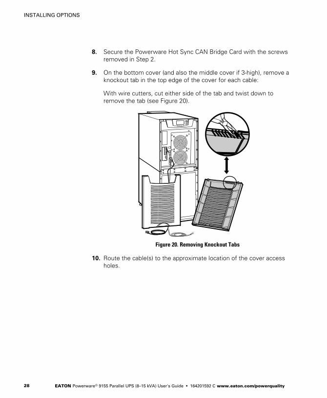
9. On the bottom cover (and also the middle cover if 3-high), remove a
knockout tab in the top edge of the cover for each cable:
With wire cutters, cut either side of the tab and twist down to
remove the tab (see Figure 20).
Figure 20. Removing Knockout Tabs
10. Route the cable(s) to the approximate location of the cover access
holes.
INSTALLING OPTIONS
EATON Powerware® 9155 Parallel UPS (8–15 kVA) User's Guide � 164201592 C www.eaton.com/powerquality 29
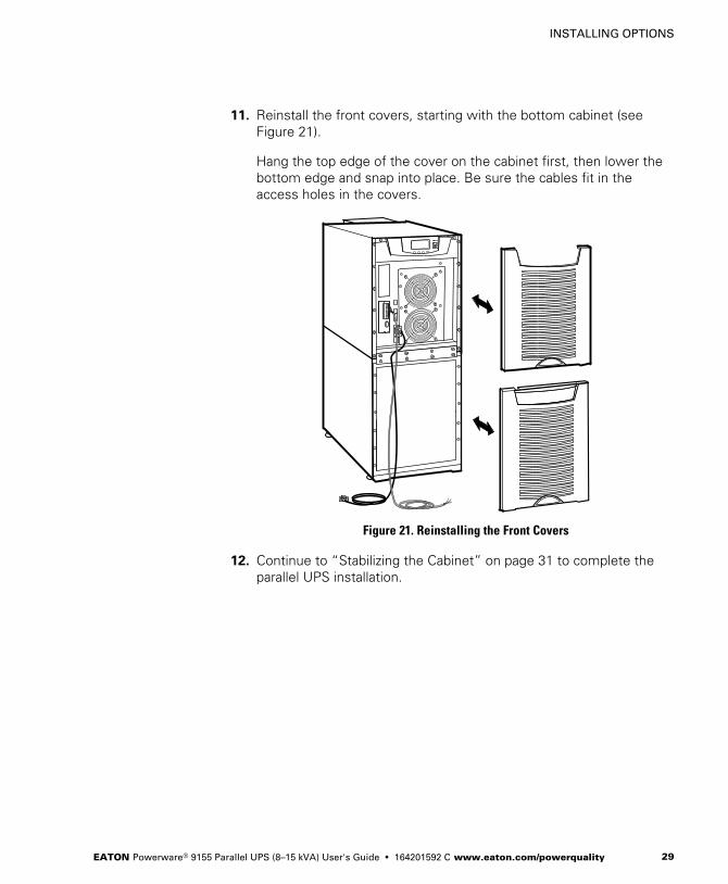
11. Reinstall the front covers, starting with the bottom cabinet (see
Figure 21).
Hang the top edge of the cover on the cabinet first, then lower the
bottom edge and snap into place. Be sure the cables fit in the
access holes in the covers.
Figure 21. Reinstalling the Front Covers
12. Continue to “Stabilizing the Cabinet” on page 31 to complete the
parallel UPS installation.

INSTALLING OPTIONS
EATON Powerware® 9155 Parallel UPS (8–15 kVA) User's Guide � 164201592 C www.eaton.com/powerquality30
EATON Powerware® 9155 Parallel UPS (8–15 kVA) User's Guide � 164201592 C www.eaton.com/powerquality 31
Chapter 6 Stabilizing the Cabinet
NOTE For seismic installations, you MUST order and install a Powerware 9155 UPS
seismic kit; do not use the following instructions.
NOTE For non-seismic installations, you MUST install the stabilizing bracket on all 3-high
cabinets. The stabilizing bracket is optional for 2-high cabinets.
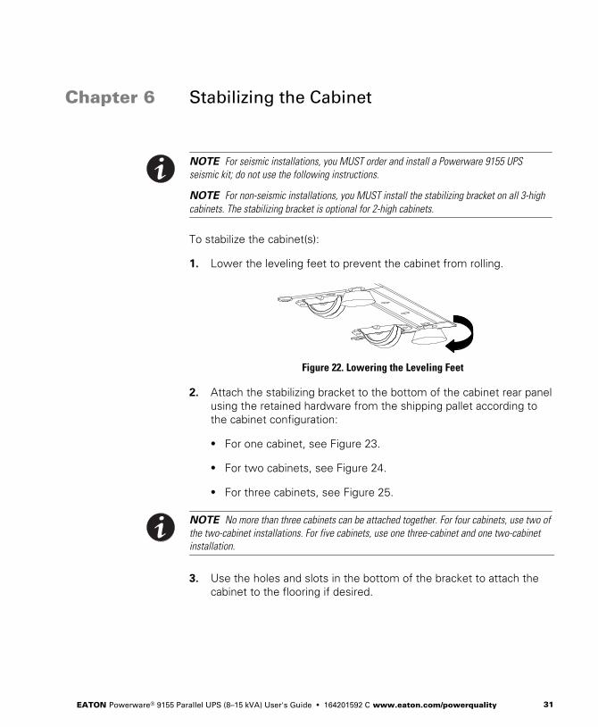
To stabilize the cabinet(s):
1. Lower the leveling feet to prevent the cabinet from rolling.
Figure 22. Lowering the Leveling Feet
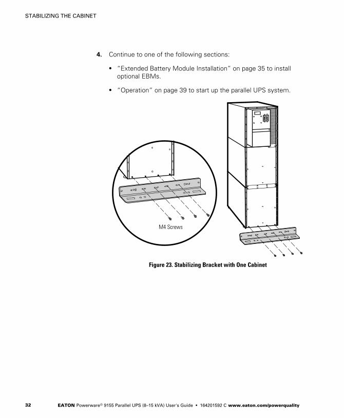
2. Attach the stabilizing bracket to the bottom of the cabinet rear panel
using the retained hardware from the shipping pallet according to
the cabinet configuration:
� For one cabinet, see Figure 23.
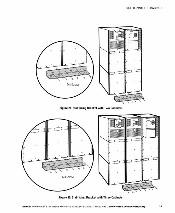
� For two cabinets, see Figure 24.
� For three cabinets, see Figure 25.
NOTE No more than three cabinets can be attached together. For four cabinets, use two of
the two-cabinet installations. For five cabinets, use one three-cabinet and one two-cabinet
installation.
3. Use the holes and slots in the bottom of the bracket to attach the
cabinet to the flooring if desired.
STABILIZING THE CABINET
EATON Powerware® 9155 Parallel UPS (8–15 kVA) User's Guide � 164201592 C www.eaton.com/powerquality32
4. Continue to one of the following sections:
� “Extended Battery Module Installation” on page 35 to install
optional EBMs.
� “Operation” on page 39 to start up the parallel UPS system.
M4 Screws
Figure 23. Stabilizing Bracket with One Cabinet
STABILIZING THE CABINET
EATON Powerware® 9155 Parallel UPS (8–15 kVA) User's Guide � 164201592 C www.eaton.com/powerquality 33
M4 Screws
Figure 24. Stabilizing Bracket with Two Cabinets
M4 Screws
Figure 25. Stabilizing Bracket with Three Cabinets

STABILIZING THE CABINET
EATON Powerware® 9155 Parallel UPS (8–15 kVA) User's Guide � 164201592 C www.eaton.com/powerquality34
EATON Powerware® 9155 Parallel UPS (8–15 kVA) User's Guide � 164201592 C www.eaton.com/powerquality 35
Chapter 7 Extended Battery Module Installation
NOTE A maximum of 22 battery strings can be installed in one configuration, including
UPS batteries (4 EBM-64 models or 3 EBM-96 models). UPS-32 models contain 2 strings;
UPS-64 models contain 4 strings; EBM-64 models contain 4 strings; and EBM-96 models
contain 6 strings.
NOTE For non-seismic installations, you MUST install the stabilizing bracket on all 3-high
cabinets. The stabilizing bracket is optional for 2-high cabinets.
NOTE In a parallel system, each UPS should have the same number of Extended Battery
Modules (EBMs) to ensure equivalent runtimes.
To install the optional EBM:
1. Position the EBM adjacent to the next cabinet.
2. Verify that all battery circuit breakers are in the OFF position (see
Figure 26).
3. Remove the two ground straps from the EBM rear panel.
4. Install one ground strap between the UPS and EBM rear panels as
shown in Figure 26.
5. If additional EBMs are installed, attach another ground strap
between the first and second EBM as shown in Figure 26. Repeat
for each additional EBM.
6. Plug the EBM cable into the UPS battery connector.
7. If additional EBMs are installed, plug the EBM cable of the second
cabinet into the battery connector on the first EBM. Repeat for each
additional EBM.

EXTENDED BATTERY MODULE INSTALLATION
EATON Powerware® 9155 Parallel UPS (8–15 kVA) User's Guide � 164201592 C www.eaton.com/powerquality36
UPS Battery Connector
Rear Ground Strap
EBM Battery Circuit Breaker
EBM Battery Connector
EBMCable
UPS Battery Circuit Breaker
ON
OFF
Figure 26. Typical EBM Installation (2-High Cabinets Shown)
EXTENDED BATTERY MODULE INSTALLATION
EATON Powerware® 9155 Parallel UPS (8–15 kVA) User's Guide � 164201592 C www.eaton.com/powerquality 37
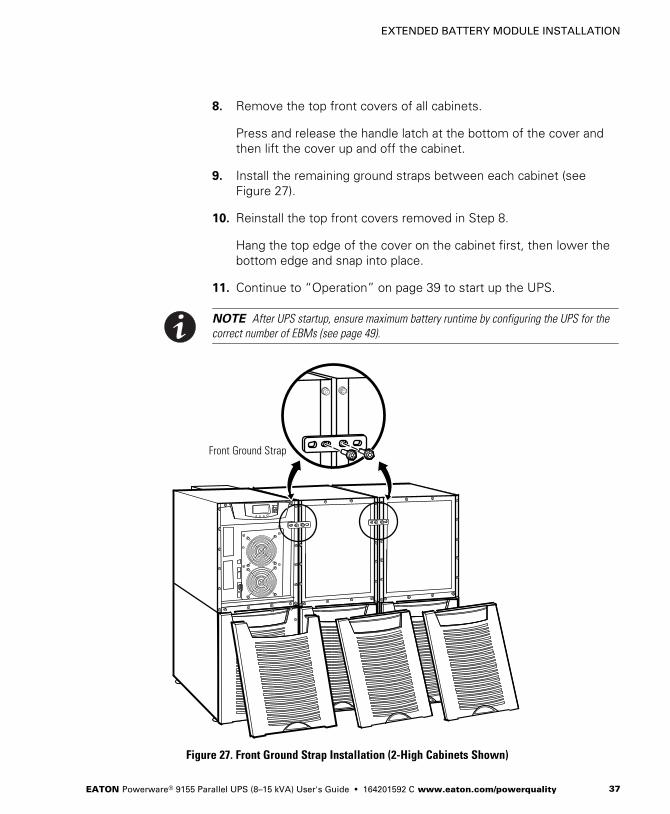
8. Remove the top front covers of all cabinets.
Press and release the handle latch at the bottom of the cover and
then lift the cover up and off the cabinet.
9. Install the remaining ground straps between each cabinet (see
Figure 27).
10. Reinstall the top front covers removed in Step 8.
Hang the top edge of the cover on the cabinet first, then lower the
bottom edge and snap into place.
11. Continue to “Operation” on page 39 to start up the UPS.
NOTE After UPS startup, ensure maximum battery runtime by configuring the UPS for the
correct number of EBMs (see page 49).
Front Ground Strap
Figure 27. Front Ground Strap Installation (2-High Cabinets Shown)

EXTENDED BATTERY MODULE INSTALLATION
EATON Powerware® 9155 Parallel UPS (8–15 kVA) User's Guide � 164201592 C www.eaton.com/powerquality38
EATON Powerware® 9155 Parallel UPS (8–15 kVA) User's Guide � 164201592 C www.eaton.com/powerquality 39
Chapter 8 Operation
This chapter contains information on how to use the Powerware 9155,
including front panel operation, UPS startup and shutdown, and
configuring the UPS for Extended Battery Modules (EBMs).
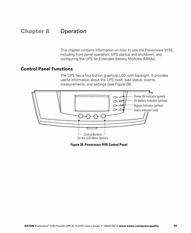
Control Panel Functions
The UPS has a four-button graphical LCD with backlight. It provides
useful information about the UPS itself, load status, events,
measurements, and settings (see Figure 28).
Power On Indicator (green)On Battery Indicator (yellow)
Bypass Indicator (yellow)
Alarm Indicator (red)
Control Buttonsfor the LCD Menu Options
Figure 28. Powerware 9155 Control Panel

OPERATION
EATON Powerware® 9155 Parallel UPS (8–15 kVA) User's Guide � 164201592 C www.eaton.com/powerquality40
The following table shows the indicator status and description.
Indicator Status Description
Green
On The UPS is operating normally.
Flashing � The UPS is starting up or is shut down and waiting for power to return.
� A new information message is active.
� Bypass is not available.
Off The UPS is turned off and will not turn on automatically.
Yellow
On The UPS is in Battery mode.
Yellow
On The UPS is in Bypass mode.
Red
On The UPS has an active alarm.
Flashing There is a new UPS alarm condition. See “Troubleshooting” on page 55 for
additional information.
Changing the Language
Press and hold the first button on the left for approximately five seconds
to select the language menu. This action is possible from any LCD menu
screen.
Display Functions
As the default or after 15 minutes of inactivity, the LCD displays the
selectable startup screen. The default is the Eaton Powerware logo and
can be changed to the Mimic screen in the User Settings menu.
The backlit LCD automatically dims after a long period of inactivity. Press
any button to restore the screen.
Use the two middle buttons ( and ) to scroll through the menu
structure. Press the button to enter a submenu. Press the button
to select an option. Press the ESC button to cancel or return to the
previous menu.
OPERATION
EATON Powerware® 9155 Parallel UPS (8–15 kVA) User's Guide � 164201592 C www.eaton.com/powerquality 41
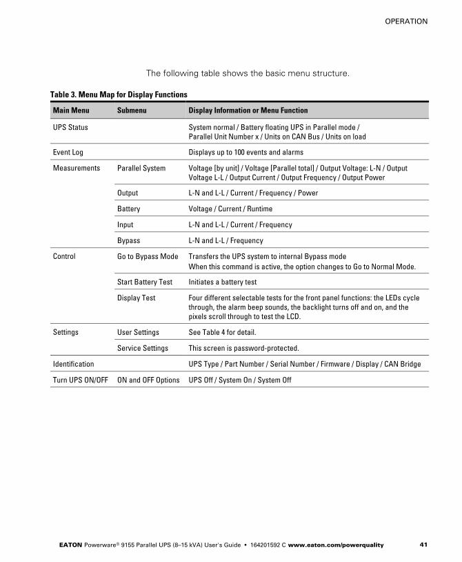
The following table shows the basic menu structure.
Table 3. Menu Map for Display Functions
Main Menu Submenu Display Information or Menu Function
UPS Status System normal / Battery floating UPS in Parallel mode /
Parallel Unit Number x / Units on CAN Bus / Units on load
Event Log Displays up to 100 events and alarms
Measurements Parallel System Voltage [by unit] / Voltage [Parallel total] / Output Voltage: L-N / Output
Voltage L-L / Output Current / Output Frequency / Output Power
Output L-N and L-L / Current / Frequency / Power
Battery Voltage / Current / Runtime
Input L-N and L-L / Current / Frequency
Bypass L-N and L-L / Frequency
Control Go to Bypass Mode Transfers the UPS system to internal Bypass mode
When this command is active, the option changes to Go to Normal Mode.
Start Battery Test Initiates a battery test
Display Test Four different selectable tests for the front panel functions: the LEDs cycle
through, the alarm beep sounds, the backlight turns off and on, and the
pixels scroll through to test the LCD.
Settings User Settings See Table 4 for detail.
Service Settings This screen is password-protected.
Identification UPS Type / Part Number / Serial Number / Firmware / Display / CAN Bridge
Turn UPS ON/OFF ON and OFF Options UPS Off / System On / System Off
OPERATION
EATON Powerware® 9155 Parallel UPS (8–15 kVA) User's Guide � 164201592 C www.eaton.com/powerquality42
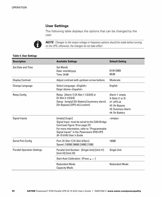
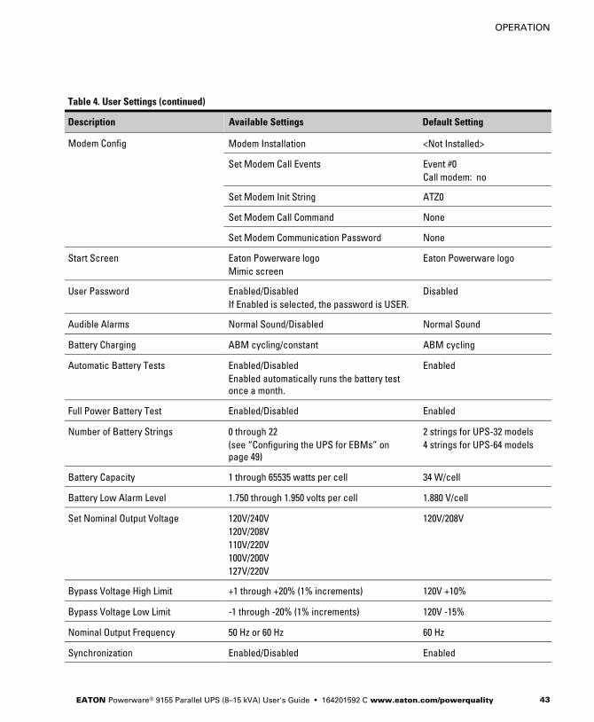
User Settings
The following table displays the options that can be changed by the
user.
NOTE Changes to the output voltage or frequency options should be made before turning
on the UPS; otherwise, the changes do not take effect.
Table 4. User Settings
Description Available Settings Default Setting
Set Date and Time Set Month
Date: mm/dd/yyyy
Time: 24:00
01/01/2003
00:00
Display Contrast Adjust contrast with up/down arrow buttons Moderate
Change Language Select Language: <English>
Elegir idioma <Español>
English
Relay Config Relay: [Alarm 1] [X-Slot 1-1/2/3/4] or
[X-Slot 2-1/2/3/4]
Setup: [empty] [On Battery] [summary alarm]
[On Bypass] [UPS ok] [custom]
Alarm 1: empty
X-Slots (1 or 2)
#1: UPS ok
#2: On Bypass
#3: Summary Alarm
#4: On Battery
Signal Inputs [empty] [Logic]
Signal Input must be wired to the CAN Bridge
Card (see Figure 19 on page 27).
For more information, refer to “Programmable
Signal Inputs” in the Powerware 9155 UPS
(8–15 kVA) User's Guide.
<empty>
Serial Port Config Port: [X-Slot-1] [X-Slot-2/Serv]
Speed: [19200] [9600] [2400] [1200]
19200
Parallel Operation Settings Parallel Unit Number: [Single Unit] [Unit #1]
[Unit #2] [Unit #3]
Single Unit
Start Auto Calibration: [Press ]
Redundant Mode
Capacity Mode
Redundant Mode
OPERATION
EATON Powerware® 9155 Parallel UPS (8–15 kVA) User's Guide � 164201592 C www.eaton.com/powerquality 43
Table 4. User Settings (continued)
Default SettingAvailable SettingsDescription
Modem Config Modem Installation <Not Installed>
Set Modem Call Events Event #0
Call modem: no
Set Modem Init String ATZ0
Set Modem Call Command None
Set Modem Communication Password None
Start Screen Eaton Powerware logo
Mimic screen
Eaton Powerware logo
User Password Enabled/Disabled
If Enabled is selected, the password is USER.
Disabled
Audible Alarms Normal Sound/Disabled Normal Sound
Battery Charging ABM cycling/constant ABM cycling
Automatic Battery Tests Enabled/Disabled
Enabled automatically runs the battery test
once a month.
Enabled
Full Power Battery Test Enabled/Disabled Enabled
Number of Battery Strings 0 through 22
(see “Configuring the UPS for EBMs” on
page 49)
2 strings for UPS-32 models
4 strings for UPS-64 models
Battery Capacity 1 through 65535 watts per cell 34 W/cell
Battery Low Alarm Level 1.750 through 1.950 volts per cell 1.880 V/cell
Set Nominal Output Voltage 120V/240V
120V/208V
110V/220V
100V/200V
127V/220V
120V/208V
Bypass Voltage High Limit +1 through +20% (1% increments) 120V +10%
Bypass Voltage Low Limit -1 through -20% (1% increments) 120V -15%
Nominal Output Frequency 50 Hz or 60 Hz 60 Hz
Synchronization Enabled/Disabled Enabled
OPERATION
EATON Powerware® 9155 Parallel UPS (8–15 kVA) User's Guide � 164201592 C www.eaton.com/powerquality44
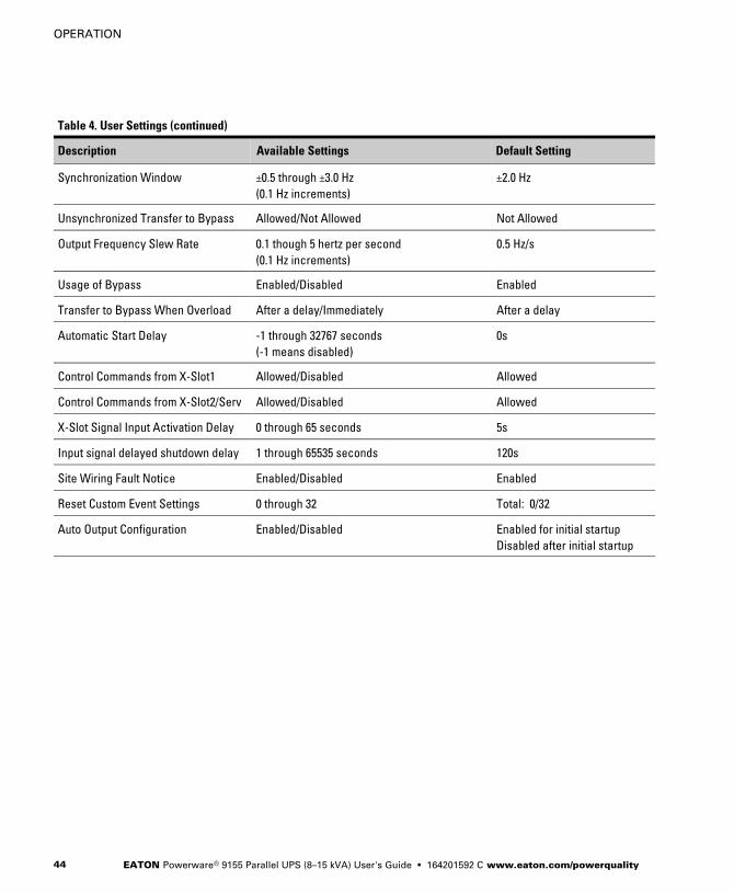
Table 4. User Settings (continued)
Default SettingAvailable SettingsDescription
Synchronization Window ±0.5 through ±3.0 Hz
(0.1 Hz increments)
±2.0 Hz
Unsynchronized Transfer to Bypass Allowed/Not Allowed Not Allowed
Output Frequency Slew Rate 0.1 though 5 hertz per second
(0.1 Hz increments)
0.5 Hz/s
Usage of Bypass Enabled/Disabled Enabled
Transfer to Bypass When Overload After a delay/Immediately After a delay
Automatic Start Delay -1 through 32767 seconds
(-1 means disabled)
0s
Control Commands from X-Slot1 Allowed/Disabled Allowed
Control Commands from X-Slot2/Serv Allowed/Disabled Allowed
X-Slot Signal Input Activation Delay 0 through 65 seconds 5s
Input signal delayed shutdown delay 1 through 65535 seconds 120s
Site Wiring Fault Notice Enabled/Disabled Enabled
Reset Custom Event Settings 0 through 32 Total: 0/32
Auto Output Configuration Enabled/Disabled Enabled for initial startup
Disabled after initial startup
OPERATION
EATON Powerware® 9155 Parallel UPS (8–15 kVA) User's Guide � 164201592 C www.eaton.com/powerquality 45
Parallel UPS Startup
W A R N I N GOnly qualified service personnel (such as a licensed electrician) should perform the UPSinstallation and initial startup. Risk of electrical shock.
Verify that UPS installation has been carried out correctly and the UPS
ground has been connected.
NOTE In a parallel capacity system (2+0 or 2+1), determine the minimum number of UPSs
required for capacity.
To start up the parallel system:
1. Verify that all UPS breakers on the parallel tie cabinet are in the OFF
position.
2. Switch on utility power where the UPSs are connected.
3. Wait for the front panel LCD to illuminate.
The indicator flashes on each UPS.
4. Remove the breaker tie from all battery circuit breakers.
5. Switch all battery circuit breakers to the ON position.
The indicator stops flashing on each UPS.
OPERATION
EATON Powerware® 9155 Parallel UPS (8–15 kVA) User's Guide � 164201592 C www.eaton.com/powerquality46
6. Configure the UPS for parallel operation through the front panel:
� Press any button on the front panel display to activate the menu
options.
� Using the button, scroll to the Settings menu, and then press
the button twice to select the User Settings menu.
� Using the button, scroll to the Parallel Operation Settings
option and press the button.
� Press the button to select the Parallel Unit Number option.
� Use the button to scroll the Unit number to identify the UPS
number of the parallel system (Unit #1, Unit #2, or Unit #3).
� Press the button to save the setting.
� Use the button to scroll to the Parallel Operation Mode option
and press the button to enter the menu.
� Use the button to scroll the desired option (either Redundant
Mode or Capacity Mode).
� Press the button to save the setting.
7. Press the ESC button until the Eaton Powerware logo appears.
8. Repeat Steps 6 and 7 for the remaining UPSs in the parallel system.

OPERATION
EATON Powerware® 9155 Parallel UPS (8–15 kVA) User's Guide � 164201592 C www.eaton.com/powerquality 47
9. Shut down each UPS:
� Press the button on the front panel display and then press the
button to select the TURN UPS ON/OFF menu.
� Press the button to select the UPS Off option; press the
button.
� Confirm the selection. Press and hold the button for three
seconds, until the UPS stops beeping.
� Switch the UPS battery circuit breaker to the OFF position.
The UPS is disconnected from the batteries and is on logic
power only.
10. Cycle the utility power to the distribution point where the parallel tie
cabinet and UPSs are connected. Wait until the LCD is off before
reapplying utility power.
11. Switch the UPS breakers on the parallel tie cabinet to the ON
position.
12. Switch all battery circuit breakers to the ON position.
13. Verify that no alarms appear on the UPS front panel display.
If the indicator is flashing, do not proceed until all alarms are
clear. Check the UPS status from the front panel to view the active
alarms. Correct the alarms and restart if necessary.
14. Verify the phase rotation for each UPS.
15. From the UPS Status menu, select the Units on CAN Bus option
and verify that all UPSs appear in the list.
If all UPSs appear in the list, press the ESC button until the Eaton
Powerware logo appears.
If any UPS is missing, verify the Powerware Hot Sync CAN Bridge
Card connections and recheck the status from the UPS front panel.
16. Press the button on the front panel display and then press the
button to select the TURN UPS ON/OFF menu.
OPERATION
EATON Powerware® 9155 Parallel UPS (8–15 kVA) User's Guide � 164201592 C www.eaton.com/powerquality48
17. Select the System On option; press the button.
18. Confirm the selection. Press and hold the button for three
seconds, until the UPS stops beeping.
The UPS goes to Bypass mode for five seconds, and then the
indicator illuminates. Each UPS should be in Normal mode.
19. Press the ESC button until the Eaton Powerware logo appears.
20. Auto-calibrate the load (with 10% minimum load recommended):
� Using the button, scroll to the Settings menu and then press
the button twice to select the User Settings menu.
� Using the button, scroll to the Parallel Operation Settings
option and press the button.
� Using the button, scroll to the Start Auto Calibration option and
press the button to select the option. Press and hold the
button for a second to begin the process.
21. After calibration completes (in less than a minute), verify the load
sharing through the front panel:
� Using the button, scroll to the Measurements menu and press
the button twice to select the Parallel System menu.
� Select and view the voltage meter options.
22. Press the ESC button until the Eaton Powerware logo appears.
OPERATION
EATON Powerware® 9155 Parallel UPS (8–15 kVA) User's Guide � 164201592 C www.eaton.com/powerquality 49
Configuring the UPS for EBMs
NOTE Each UPS in a parallel system must have its own EBM and the same number of
EBMs to ensure consistent runtimes.
To ensure maximum battery runtime, configure the UPS for the correct
number of EBMs:
1. Press any button on the front panel display to activate the menu
options.
2. Using the button, scroll to the Settings menu.
3. Press the button twice to select the User Settings menu.
4. Using the button, scroll to the Number of Battery Strings option
and press the button.
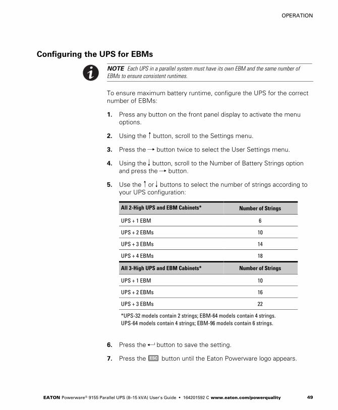
5. Use the or buttons to select the number of strings according to
your UPS configuration:
All 2-High UPS and EBM Cabinets* Number of Strings
UPS + 1 EBM 6
UPS + 2 EBMs 10
UPS + 3 EBMs 14
UPS + 4 EBMs 18
All 3-High UPS and EBM Cabinets* Number of Strings
UPS + 1 EBM 10
UPS + 2 EBMs 16
UPS + 3 EBMs 22
*UPS-32 models contain 2 strings; EBM-64 models contain 4 strings.
UPS-64 models contain 4 strings; EBM-96 models contain 6 strings.
6. Press the button to save the setting.
7. Press the ESC button until the Eaton Powerware logo appears.
OPERATION
EATON Powerware® 9155 Parallel UPS (8–15 kVA) User's Guide � 164201592 C www.eaton.com/powerquality50
Parallel System Shutdown
To remove power to the parallel UPS system output:
1. Press any button on the front panel display to activate the menu
options.
2. Press the button on the front panel display and then press the
button to select the TURN UPS ON/OFF menu.
3. Press the button to select the System Off option; press the
button.
4. Confirm the selection. Press and hold the button for three
seconds, until the UPS stops beeping.
The UPS removes power to the parallel UPS system output.
5. Press the ESC button until the Eaton Powerware logo appears.
6. If you want to completely remove power from the UPS, continue to
the following section, “Individual UPS Shutdown,” to shut down
each UPS.
OPERATION
EATON Powerware® 9155 Parallel UPS (8–15 kVA) User's Guide � 164201592 C www.eaton.com/powerquality 51
Individual UPS Shutdown
To shut down a single UPS in the parallel system:
1. Press any button on the front panel display to activate the menu
options.
2. Press the button on the front panel display and then press the
button to select the TURN UPS ON/OFF menu.
3. Press the button to select the UPS Off option; press the
button.
4. Confirm the selection. Press and hold the button for three
seconds, until the UPS stops beeping.
The input contactor opens.
5. Switch the UPS battery circuit breaker to the OFF position.
The UPS is disconnected from the batteries and is on logic power
only.
6. Switch the UPS breaker on the parallel tie cabinet to the OFF
position.
NOTE If there is only one breaker for all UPSs, do not switch off utility power until all UPSs
are shut down.
7. Switch off utility power where the UPS is connected.
If you are shutting down all the UPSs in a parallel system, repeat
Steps 2 through 6 for each UPS then remove utility power.
OPERATION
EATON Powerware® 9155 Parallel UPS (8–15 kVA) User's Guide � 164201592 C www.eaton.com/powerquality52
Restarting the Parallel System
To restart the parallel system:
1. Verify that all UPS breakers on the parallel tie cabinet are in the OFF
position.
2. Switch on utility power where the UPSs are connected.
3. Wait for the front panel LCD to illuminate.
The indicator flashes on each UPS.
4. Switch all battery circuit breakers to the ON position.
The indicator stops flashing on each UPS.
5. Switch the UPS breakers on the parallel tie cabinet to the ON
position.
6. Verify that no alarms appear on the UPS front panel display.
If the indicator is flashing, do not proceed until all alarms are
clear. Check the UPS status from the front panel to view the active
alarms. Correct the alarms and restart if necessary.
7. Press the ESC button once and then press the button to select
the TURN UPS ON/OFF menu.
8. Press the button to select the System On option; press the
button.
9. Confirm the selection. Press and hold the button for three
seconds, until the UPS stops beeping.
The UPS goes to Bypass mode for five seconds, and then the
indicator illuminates. Each UPS should be in Normal mode.
10. Press the ESC button until the Eaton Powerware logo appears.
EATON Powerware® 9155 Parallel UPS (8–15 kVA) User's Guide � 164201592 C www.eaton.com/powerquality 53
Chapter 9 Parallel Bypass
To switch the parallel UPS to maintenance bypass from Normal mode:
1. From any UPS, set the system to internal Bypass mode:
� Using the button on the front panel display, scroll to the Control
menu option and press the button.
� Press the button to select the Go to Bypass Mode option.
The and indicators illuminate, indicating the UPS system
is operating in Bypass mode.
2. Switch the bypass breaker on the parallel tie cabinet to the ON
position.
3. Switch the UPS breakers on the parallel tie cabinet to the OFF
position.
PARALLEL BYPASS
EATON Powerware® 9155 Parallel UPS (8–15 kVA) User's Guide � 164201592 C www.eaton.com/powerquality54
To return to Normal mode from maintenance bypass:
1. Verify that all UPS breakers on the parallel tie cabinet are in the OFF
position.
2. Switch on utility power where the UPSs are connected.
In a parallel capacity system (2+0 or 2+1), apply utility to the
minimum number of UPSs required for capacity.
NOTE Use the same UPS that was used to set internal bypass to return the parallel system
to Normal mode.
3. Set the system to internal Bypass mode:
� Using the button on the front panel display, scroll to the Control
menu option and press the button.
� Press the button to select the Go to Bypass Mode option.
The and indicators illuminate, indicating the UPS system
is operating in Bypass mode.
4. Switch all UPS breakers on the parallel tie cabinet to the ON
position.
5. Switch the bypass breaker on the parallel tie cabinet to the OFF
position.
6. On the same UPS front panel, set the UPS to Normal mode:
� Press the button to select the Go to Normal Mode option.
� Each UPS should go to Normal mode.
EATON Powerware® 9155 Parallel UPS (8–15 kVA) User's Guide � 164201592 C www.eaton.com/powerquality 55
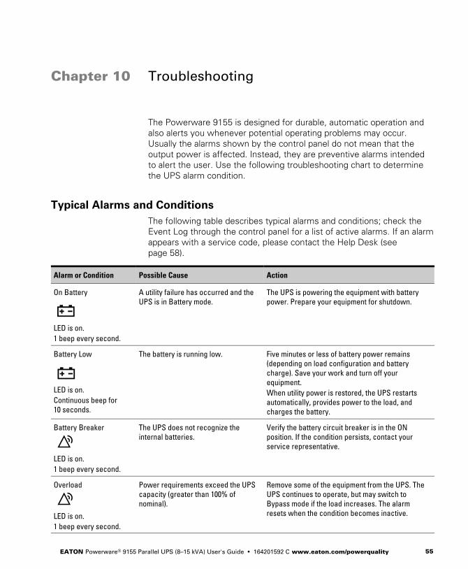
Chapter 10 Troubleshooting
The Powerware 9155 is designed for durable, automatic operation and
also alerts you whenever potential operating problems may occur.
Usually the alarms shown by the control panel do not mean that the
output power is affected. Instead, they are preventive alarms intended
to alert the user. Use the following troubleshooting chart to determine
the UPS alarm condition.
Typical Alarms and Conditions
The following table describes typical alarms and conditions; check the
Event Log through the control panel for a list of active alarms. If an alarm
appears with a service code, please contact the Help Desk (see
page 58).
Alarm or Condition Possible Cause Action
On Battery
LED is on.
1 beep every second.
A utility failure has occurred and the
UPS is in Battery mode.
The UPS is powering the equipment with battery
power. Prepare your equipment for shutdown.
Battery Low
LED is on.
Continuous beep for
10 seconds.
The battery is running low. Five minutes or less of battery power remains
(depending on load configuration and battery
charge). Save your work and turn off your
equipment.
When utility power is restored, the UPS restarts
automatically, provides power to the load, and
charges the battery.
Battery Breaker
LED is on.
1 beep every second.
The UPS does not recognize the
internal batteries.
Verify the battery circuit breaker is in the ON
position. If the condition persists, contact your
service representative.
Overload
LED is on.
1 beep every second.
Power requirements exceed the UPS
capacity (greater than 100% of
nominal).
Remove some of the equipment from the UPS. The
UPS continues to operate, but may switch to
Bypass mode if the load increases. The alarm
resets when the condition becomes inactive.
TROUBLESHOOTING
EATON Powerware® 9155 Parallel UPS (8–15 kVA) User's Guide � 164201592 C www.eaton.com/powerquality56
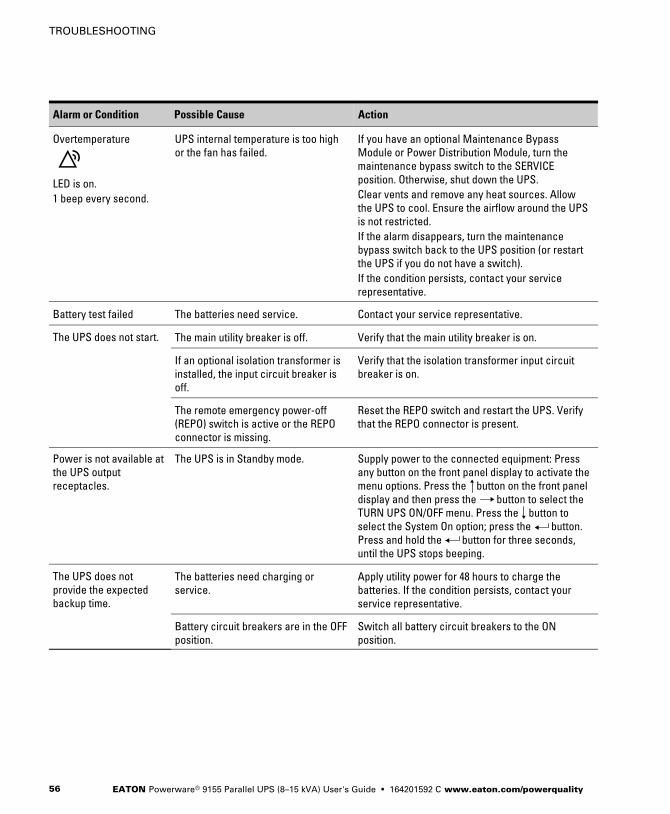
ActionPossible CauseAlarm or Condition
Overtemperature
LED is on.
1 beep every second.
UPS internal temperature is too high
or the fan has failed.
If you have an optional Maintenance Bypass
Module or Power Distribution Module, turn the
maintenance bypass switch to the SERVICE
position. Otherwise, shut down the UPS.
Clear vents and remove any heat sources. Allow
the UPS to cool. Ensure the airflow around the UPS
is not restricted.
If the alarm disappears, turn the maintenance
bypass switch back to the UPS position (or restart
the UPS if you do not have a switch).
If the condition persists, contact your service
representative.
Battery test failed The batteries need service. Contact your service representative.
The UPS does not start. The main utility breaker is off. Verify that the main utility breaker is on.
If an optional isolation transformer is
installed, the input circuit breaker is
off.
Verify that the isolation transformer input circuit
breaker is on.
The remote emergency power-off
(REPO) switch is active or the REPO
connector is missing.
Reset the REPO switch and restart the UPS. Verify
that the REPO connector is present.
Power is not available at
the UPS output
receptacles.
The UPS is in Standby mode. Supply power to the connected equipment: Press
any button on the front panel display to activate the
menu options. Press the button on the front panel
display and then press the button to select the
TURN UPS ON/OFF menu. Press the button to
select the System On option; press the button.
Press and hold the button for three seconds,
until the UPS stops beeping.
The UPS does not
provide the expected
backup time.
The batteries need charging or
service.
Apply utility power for 48 hours to charge the
batteries. If the condition persists, contact your
service representative.
Battery circuit breakers are in the OFF
position.
Switch all battery circuit breakers to the ON
position.
TROUBLESHOOTING
EATON Powerware® 9155 Parallel UPS (8–15 kVA) User's Guide � 164201592 C www.eaton.com/powerquality 57
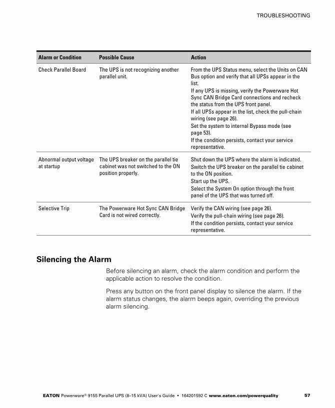
ActionPossible CauseAlarm or Condition
Check Parallel Board The UPS is not recognizing another
parallel unit.
From the UPS Status menu, select the Units on CAN
Bus option and verify that all UPSs appear in the
list.
If any UPS is missing, verify the Powerware Hot
Sync CAN Bridge Card connections and recheck
the status from the UPS front panel.
If all UPSs appear in the list, check the pull-chain
wiring (see page 26).
Set the system to internal Bypass mode (see
page 53).
If the condition persists, contact your service
representative.
Abnormal output voltage
at startup
The UPS breaker on the parallel tie
cabinet was not switched to the ON
position properly.
Shut down the UPS where the alarm is indicated.
Switch the UPS breaker on the parallel tie cabinet
to the ON position.
Start up the UPS.
Select the System On option through the front
panel of the UPS that was turned off.
Selective Trip The Powerware Hot Sync CAN Bridge
Card is not wired correctly.
Verify the CAN wiring (see page 26).
Verify the pull-chain wiring (see page 26).
If the condition persists, contact your service
representative.
Silencing the Alarm
Before silencing an alarm, check the alarm condition and perform the
applicable action to resolve the condition.
Press any button on the front panel display to silence the alarm. If the
alarm status changes, the alarm beeps again, overriding the previous
alarm silencing.
TROUBLESHOOTING
EATON Powerware® 9155 Parallel UPS (8–15 kVA) User's Guide � 164201592 C www.eaton.com/powerquality58
Service and Support
If you have any questions or problems with the UPS, call your LocalDistributor or the Help Desk at one of the following telephone numbers
and ask for a UPS technical representative.
United States: 1-800-843-9433 or 1-919-870-3028
Canada: 1-800-461-9166 ext 260
All other countries: Call your local service representative
Please have the following information ready when you call for service:
� Model number
� Serial number
� Firmware version number
� Date of failure or problem
� Symptoms of failure or problem
� Customer return address and contact information


*164201592C*164201592 C