PowerView Models PV350 & PV380 R2 - Enovation Controls · Red and amber warning LEDs; set point...
20
Sec 78/00-02-0998 2017-06-12 PowerView ® Models PV350 & PV380 R2 Installation Manual
-
Upload
truongdiep -
Category
Documents
-
view
220 -
download
0
Transcript of PowerView Models PV350 & PV380 R2 - Enovation Controls · Red and amber warning LEDs; set point...
Sec 78/00-02-0998 2017-06-12
PowerView®
Models PV350 & PV380 R2
Installation Manual

Sec 78/00-02-0998 2017-06-12
Products covered in this document comply with European Council electromagnetic compatibility directive 2004/108/EC and electrical safety directive 2006/95/EC.
In order to consistently bring you the highest quality, full-featured products, we reserve the right to change our specifications and designs at any time. The latest version of this manual can be found at www.MurphyByEnovationControls.com/PV380.
Warranty - A limited warranty on materials and workmanship is given with this Murphy product. A copy of the warranty may be viewed or printed by
going to www.MurphyByEnovationControls.com/warranty

Sec 78/00-02-0998 2017-06-12
Table of Contents
Hardware Installation ........................................... 5 Inspecting Package Contents ...................... 5 Dash-Mounted Installation ........................... 6 Dimensions .................................................. 7
Wiring Information .............................................. 9 Pin Specifications for PV350 ....................... 9 Pin Specifications for PV380 ..................... 10 Wiring Diagram for PV350 ......................... 12 Wiring Diagram for PV380 ......................... 13 PV350 and PV380 Features and Operations................................................................... 14
Specifications ..................................................... 16

Sec 78/00-02-0998 2017-06-12
- This page intentionally left blank -

00-02-0998 5 2017-06-12
Hardware Installation
The following instructions will guide you through installing the PowerView display.
Inspecting Package Contents
Before attempting to install the product, it is recommended that you ensure all parts are accounted for and inspect each item for damage (which sometimes occurs during shipping). The items included in the box are:
• PV350 or the PV380 unit • Dash gasket • Installation manual – P/N 00-02-0998
The PV350 and PV380 R2 Operations Manuals can be found online at:
www.MurphyByEnovationControls.com/PV350 www.MurphyByEnovationControls.com/PV380

00-02-0998 6 2017-06-12
Dash-Mounted Installation
Tools needed
• Jig saw or • 3.5” Hole saw or • 3.5” knockout (chassis) punch
Preparing the Dash
Determine the location of the PowerView in the dash. Refer to the Mounting Hole Options sheet at the end of this document for the appropriate opening sizes.
Mounting the Unit
1. Place the dash gasket over the prepared dash opening.
2. Place the back side of the display through the opening in the dash.
3. Push the unit through the opening until the case is flush.
4. Place the screw-on type mounting clamp behind the dash and install on the unit until it is hand tight.

00-02-0998 7 2017-06-12
Dimensions

00-02-0998 8 2017-06-12
Dimensions, cont.

00-02-0998 9 2017-06-12
Wiring Information
Pin Specifications for PV350
00-02-0998 10 2017-06-12
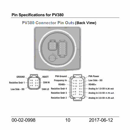
Pin Specifications for PV380

00-02-0998 11 2017-06-12
PV350 Mating Connector Part Numbers:
• Deutsch DT06-12SA plug housing • Deutsch DT06-6S plug housing • W6S and W12S wedge locks • Deutsch 0462-201-16141 contact (socket) • M12 (Micro-C) 5-pin male plug compatible with NMEA
2000 thin backbones (light cable)
PV380 Mating Connector Part Numbers:
• Deutsch DT06-12SA plug housing • Deutsch DT06-6S plug housing • W6S and W12S wedge locks • Deutsch 0462-201-16141 contact (socket)

00-02-0998 12 2017-06-12
Wiring Diagram for PV350

00-02-0998 13 2017-06-12
Wiring Diagram for PV380

00-02-0998 14 2017-06-12
PV350 and PV380 Features and Operations
00-02-0998 15 2017-06-12
Flat Screen Display A 3.8” QVGA monochrome LCD screen displays gauges, soft key commands and fault messages as well as menu options for setup and configuration.
Soft Keys and Commands The five tactile push buttons on the bottom of the display correspond to the options available for the screen being displayed.
Alarms Red and amber warning LEDs; set point triggered output for external piezo buzzer or shut-down relay.
Operations Manual
The PV350/PV380 Murphy Standard Configuration Operation manuals can be found at www.MurphyByEnovationControls.com/PV350 and www.MurphyByEnovationControls.com/PV380.

00-02-0998 16 2017-06-12
Specifications Electrical Display 3.8” monochrome LCD Resolution QVGA, 320 x 240 pixels Orientation Landscape Backlighting LED, white Flash Memory 2Mb RAM 256kb
Operating Voltage 6 - 36 VDC, protected against reverse polarity and load-dump
Power Consumption 10 W max
Communications
PV350: (2) CAN 2.0B NMEA 2000 isolated (second port)
PV380: (1) CAN 2.0B (1) RS485 serial (Modbus)
Protocols J1939, FreeForm CAN

00-02-0998 17 2017-06-12
Connection
PV350: 6 pin Deutsch connector and 5 pin M12 connector PV380: 6 pin and 12 pin Deutsch DT series connectors
Keyboard 5 tactile buttons
Inputs
PV350: (1) resistive analog (backlight control)
PV380: (4) resistive analog (3) analog, 0-5V / 4-20 mA (1) frequency, 20-10,000 Hz, 3.6-
120 VAC
Output PV350: (1) 500 mA; switched low-side PV380: (2) 500 mA; switched low-side
Environmental Operating Temperature -40º C to +85º C
Storage Temperature -40º C to +85º C
Protection IP67, front and back, IP66 panel seal
00-02-0998 18 2017-06-12
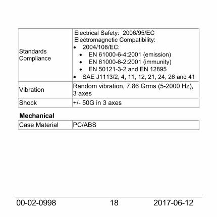
Standards Compliance
Electrical Safety: 2006/95/EC Electromagnetic Compatibility: • 2004/108/EC: • EN 61000-6-4:2001 (emission) • EN 61000-6-2:2001 (immunity) • EN 50121-3-2 and EN 12895
• SAE J1113/2, 4, 11, 12, 21, 24, 26 and 41
Vibration Random vibration, 7.86 Grms (5-2000 Hz), 3 axes
Shock +/- 50G in 3 axes
Mechanical Case Material PC/ABS

00-02-0998 19 2017-06-12
Mounting Hole Options