PowerView Model PV780 - Enovation Controls
16
00-02-0860 2016-06-30 Section 78 PowerView ® Model PV780 Installation Manual
Transcript of PowerView Model PV780 - Enovation Controls

00-02-0860 2016-06-30 Section 78
PowerView® Model PV780
Installation Manual

In order to consistently bring you the highest quality, full-featured products, we reserve the right to change our specifications and designs at any time. The latest version of this manual can be found at www.fwmurphy.com.
Please read the following information before installing.
BEFORE BEGINNING INSTALLATION OF THIS MURPHY PRODUCT:
Read and follow all installation instructions. Please contact Enovation Controls immediately if you have any questions.

Table of Contents Hardware Installation ................................................................................................................. 1
Inspecting Package Contents .......................................................................................1
Dash-Mounted Installation............................................................................................1
RAM™ Mount Option ...................................................................................................3
Wiring Information ..................................................................................................................... 4
Pin Out Specifications ..................................................................................................4
Wiring Schematics – Black Connector .........................................................................5
Wiring Schematics – Gray Connector ..........................................................................6
Specifications ............................................................................................................................. 7
Dimensions ................................................................................................................................. 9

THIS PAGE INTENTIONALLY LEFT BLANK
Section 78 00-02-0860 2016-06-30 - 1 -
Hardware Installation The following instructions will guide you through installing the PowerView display.
Inspecting Package Contents Before attempting to install the product, it is recommended that you ensure all parts are accounted for and inspect each item for damage (which sometimes occurs during shipping). The items included in the box are:
PV780 unit Installation kit – P/N 78-00-0638 includes:
• Four each machine screws and flat washers
• Four Nylock nuts
• Installation & Operations manual web reference insert
Dash-Mounted Installation
Tools needed. • Drill with 5/32 in. size bit
• Jigsaw
• Wrench or socket 6-32 Nylock nuts (provided) to studs
Preparing the Dash
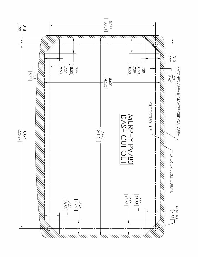
Determine the location of the PowerView in the dash. Use the Installation Template (included at the end of the manual) as a guideline to cut a hole in the dash to the specified dimensions. Drill holes where indicated on the template for the mounting screws.
NOTE: When using the paper template from the manual, if you downloaded this document from the FW Murphy website, be aware that the pdf file may not automatically print to scale. When submitting the file for print, you will need to select None for Page Scaling. Check the accuracy of the printed template by verifying the measurements labeled on the template are correct. If this manual was supplied with your product, the template will be correct.
Section 78 00-02-0860 2016-06-30 - 2 -
Mounting the Unit
1. Place the back side of the display through the opening in the dash.
2. Use the four screws to line up the unit with the drilled holes.
3. Push the unit through the opening and screws through the drilled holes until the back of the case is flush.
4. Use the Nylock nuts provided to tighten unit to the dash. Use the appropriate wrench or socket to tighten. Torque lock nuts to 8-10 inch-pounds.
Flush Mounting the Dash
1. Cut the dash to allow for the display without bezel. Carefully follow the measurements of the included dash cut-out to ensure enough of the dash is available to properly secure the display. Torque the 6-32 Nylock nuts to 5 inch-pounds.
2. Place the display behind dash and line up the four mounting holes on the display with the holes in dash.
3. Install four bolts and tighten nuts.
Section 78 00-02-0860 2016-06-30 - 3 -
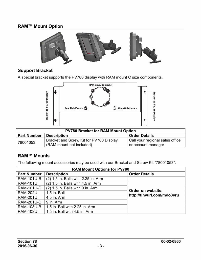
RAM™ Mount Option
Support Bracket A special bracket supports the PV780 display with RAM mount C size components.
PV780 Bracket for RAM Mount Option
Part Number Description Order Details
78001053 Bracket and Screw Kit for PV780 Display (RAM mount not included)
Call your regional sales office or account manager.
RAM™ Mounts The following mount accessories may be used with our Bracket and Screw Kit “78001053”.
RAM Mount Options for PV780 Part Number Description Order Details RAM-101U-B (2) 1.5 in. Balls with 2.25 in. Arm
Order on website: http://tinyurl.com/mdo3yru
RAM-101U (2) 1.5 in. Balls with 4.5 in. Arm RAM-101U-D (2) 1.5 in. Balls with 9 in. Arm RAM-202U 1.5 in. Ball RAM-201U 4.5 in. Arm RAM-201U-D 9 in. Arm RAM-103U-B 1.5 in. Ball with 2.25 in. Arm RAM-103U 1.5 in. Ball with 4.5 in. Arm
Section 78 00-02-0860 2016-06-30 - 4 -
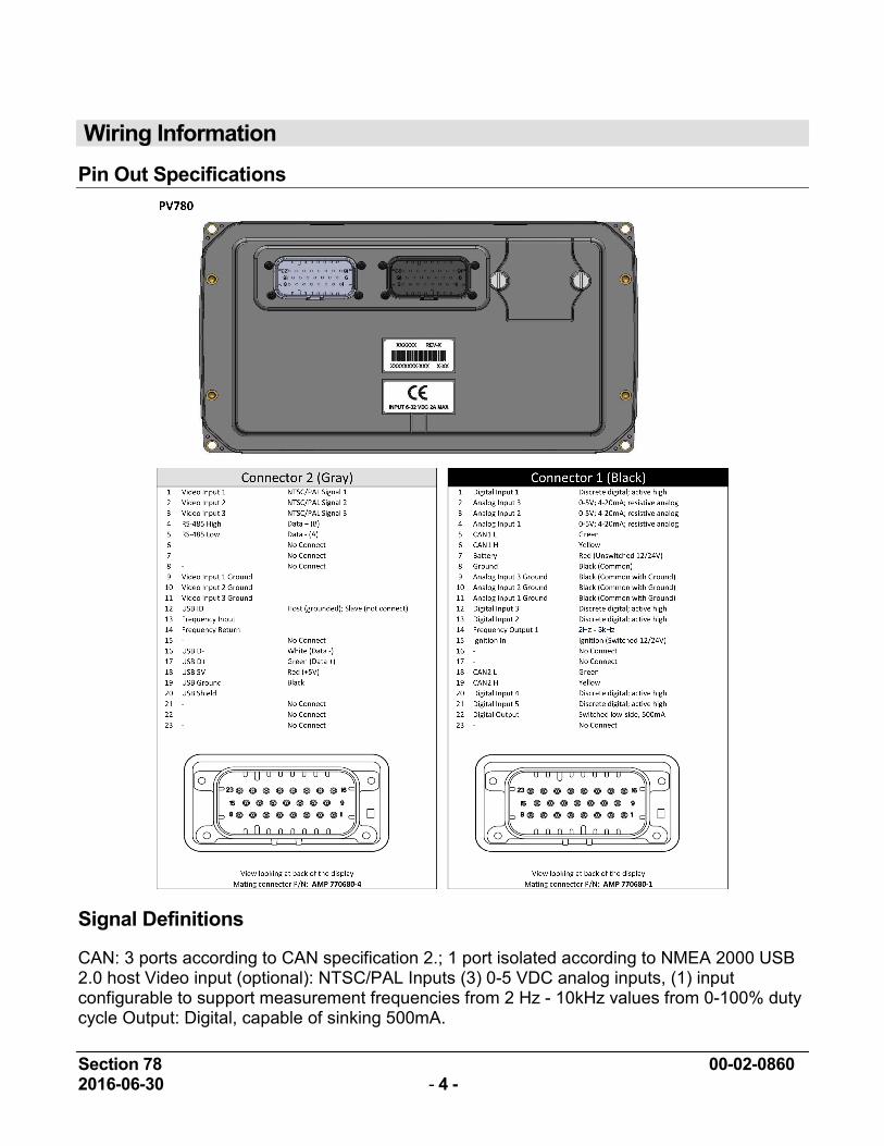
Wiring Information Pin Out Specifications
Signal Definitions
CAN: 3 ports according to CAN specification 2.; 1 port isolated according to NMEA 2000 USB 2.0 host Video input (optional): NTSC/PAL Inputs (3) 0-5 VDC analog inputs, (1) input configurable to support measurement frequencies from 2 Hz - 10kHz values from 0-100% duty cycle Output: Digital, capable of sinking 500mA.
Section 78 00-02-0860 2016-06-30 - 5 -
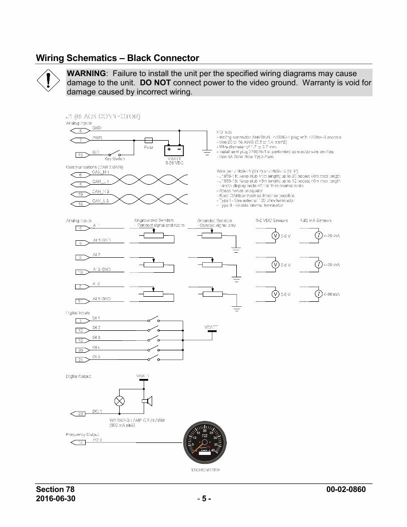
Wiring Schematics – Black Connector WARNING: Failure to install the unit per the specified wiring diagrams may cause damage to the unit. DO NOT connect power to the video ground. Warranty is void for damage caused by incorrect wiring.
Section 78 00-02-0860 2016-06-30 - 6 -
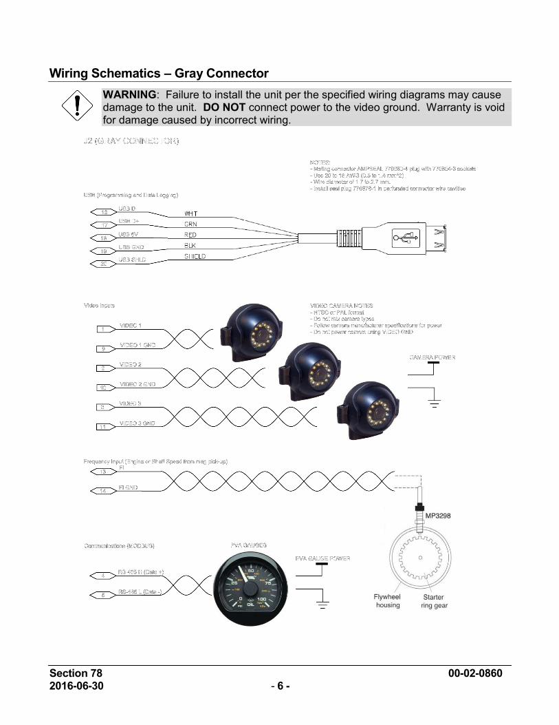
Wiring Schematics – Gray Connector WARNING: Failure to install the unit per the specified wiring diagrams may cause damage to the unit. DO NOT connect power to the video ground. Warranty is void for damage caused by incorrect wiring.
Section 78 00-02-0860 2016-06-30 - 7 -
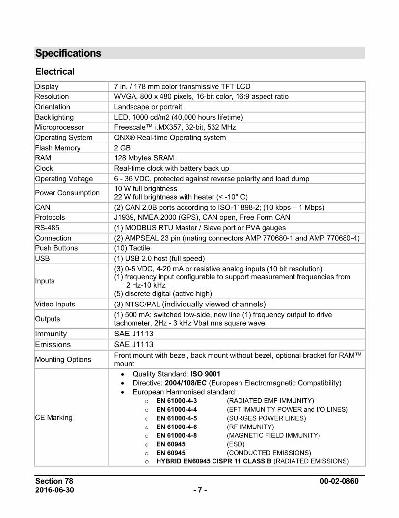
Specifications Electrical Display 7 in. / 178 mm color transmissive TFT LCD Resolution WVGA, 800 x 480 pixels, 16-bit color, 16:9 aspect ratio Orientation Landscape or portrait Backlighting LED, 1000 cd/m2 (40,000 hours lifetime) Microprocessor Freescale™ i.MX357, 32-bit, 532 MHz Operating System QNX® Real-time Operating system Flash Memory 2 GB RAM 128 Mbytes SRAM Clock Real-time clock with battery back up Operating Voltage 6 - 36 VDC, protected against reverse polarity and load dump
Power Consumption 10 W full brightness 22 W full brightness with heater (< -10° C)
CAN (2) CAN 2.0B ports according to ISO-11898-2; (10 kbps – 1 Mbps) Protocols J1939, NMEA 2000 (GPS), CAN open, Free Form CAN RS-485 (1) MODBUS RTU Master / Slave port or PVA gauges Connection (2) AMPSEAL 23 pin (mating connectors AMP 770680-1 and AMP 770680-4) Push Buttons (10) Tactile USB (1) USB 2.0 host (full speed)
Inputs
(3) 0-5 VDC, 4-20 mA or resistive analog inputs (10 bit resolution) (1) frequency input configurable to support measurement frequencies from 2 Hz-10 kHz (5) discrete digital (active high)
Video Inputs (3) NTSC/PAL (individually viewed channels)
Outputs (1) 500 mA; switched low-side, new line (1) frequency output to drive tachometer, 2Hz - 3 kHz Vbat rms square wave
Immunity SAE J1113 Emissions SAE J1113
Mounting Options Front mount with bezel, back mount without bezel, optional bracket for RAM™ mount
CE Marking
• Quality Standard: ISO 9001 • Directive: 2004/108/EC (European Electromagnetic Compatibility) • European Harmonised standard:
o EN 61000-4-3 (RADIATED EMF IMMUNITY) o EN 61000-4-4 (EFT IMMUNITY POWER and I/O LINES) o EN 61000-4-5 (SURGES POWER LINES) o EN 61000-4-6 (RF IMMUNITY) o EN 61000-4-8 (MAGNETIC FIELD IMMUNITY) o EN 60945 (ESD) o EN 60945 (CONDUCTED EMISSIONS) o HYBRID EN60945 CISPR 11 CLASS B (RADIATED EMISSIONS)
Section 78 00-02-0860 2016-06-30 - 8 -
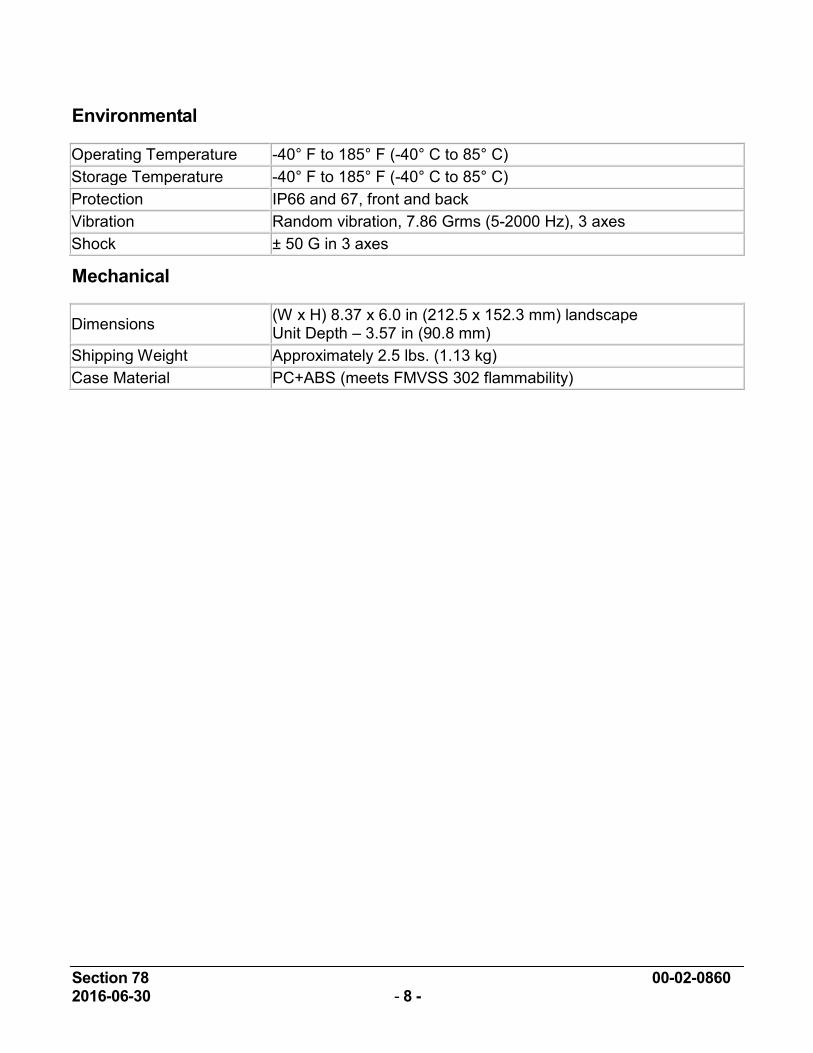
Environmental
Operating Temperature -40° F to 185° F (-40° C to 85° C) Storage Temperature -40° F to 185° F (-40° C to 85° C) Protection IP66 and 67, front and back Vibration Random vibration, 7.86 Grms (5-2000 Hz), 3 axes Shock ± 50 G in 3 axes
Mechanical
Dimensions (W x H) 8.37 x 6.0 in (212.5 x 152.3 mm) landscape Unit Depth – 3.57 in (90.8 mm)
Shipping Weight Approximately 2.5 lbs. (1.13 kg) Case Material PC+ABS (meets FMVSS 302 flammability)
Section 78 00-02-0860 2016-06-30 - 9 -
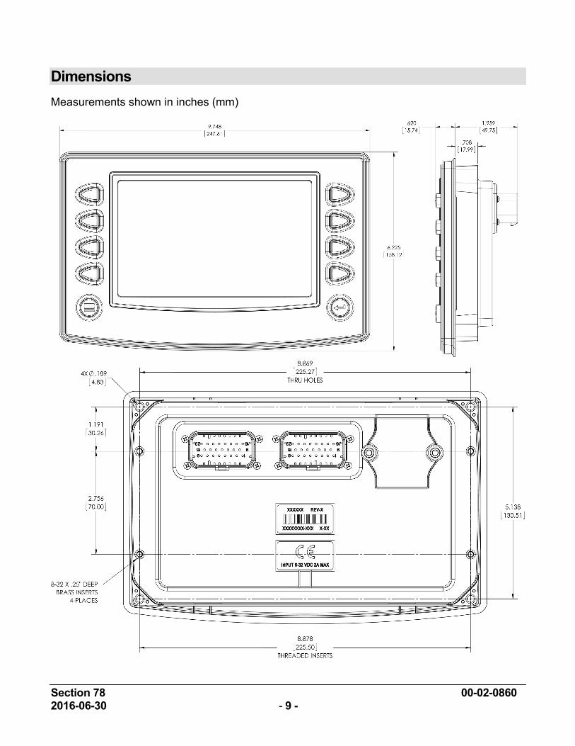
Dimensions Measurements shown in inches (mm)

THIS PAGE INTENTIONALLY LEFT BLANK