Power&System&Technologies&for& Future&Venus&Missions& · Performance of SOP Solar Cells and Arrays...
42
Power System Technologies for Future Venus Missions Presenta9on to Venus Technology Forum Rao Surampudi, Sa9sh Khanna, Jonathan Grandidier, Kumar Bugga Nov 19, 2013
Transcript of Power&System&Technologies&for& Future&Venus&Missions& · Performance of SOP Solar Cells and Arrays...

Power System Technologies for Future Venus Missions
Presenta9on to
Venus Technology Forum
Rao Surampudi, Sa9sh Khanna, Jonathan Grandidier, Kumar Bugga Nov 19, 2013
Outline
• Power System Technology Needs of Venus Explora9on Missions
• Poten9al Power System Technologies for Future Venus Explora9on Missions – Nuclear Power systems ( SOP& Advanced) – Solar Arrays (SOP & Advanced) – Energy Storage systems (SOP & Advanced)
• Summary & Conclusions

Power System Technology Needs for Venus Explora9on Mission

Types of Venus Explora9on Missions
• Orbital Missions
• Aerial Missions – Balloons-‐Constant Al9tude – Balloons-‐Variable al9tude – Airplanes – Hybrid Vehicles
• Surface Missions – Short Dura9on (Probes,
Landers) – Long Dura9on (Landers,
Probes, Rovers)
4

Power System Needs for Venus Explora9on Missions
• Capable of Opera9on in Venus environments – High Temperature – Corrosive Environments
• High Specific Energy /Power (Low Mass) • High Energy/power Density (Low Volume)
• Long Life
Venus Environment Challenges for Power system Technologies
• High Temperature ( > 450 C)
• Corrosive Environment (sulfuric acid)
• High Solar intensity
• Nature of Solar spectrum

Venus Atmosphere Temperature (in °C) as a func9on of al9tude
The surface temperature of Venus is about 460°C. Temperature in the Venus atmosphere decreases with al9tude, with a lapse of about 7.7 °C per kilometer.

Solar Spectrum in the Venus Atmosphere
Solar intensity becomes significantly a`enuated at lower al9tudes.
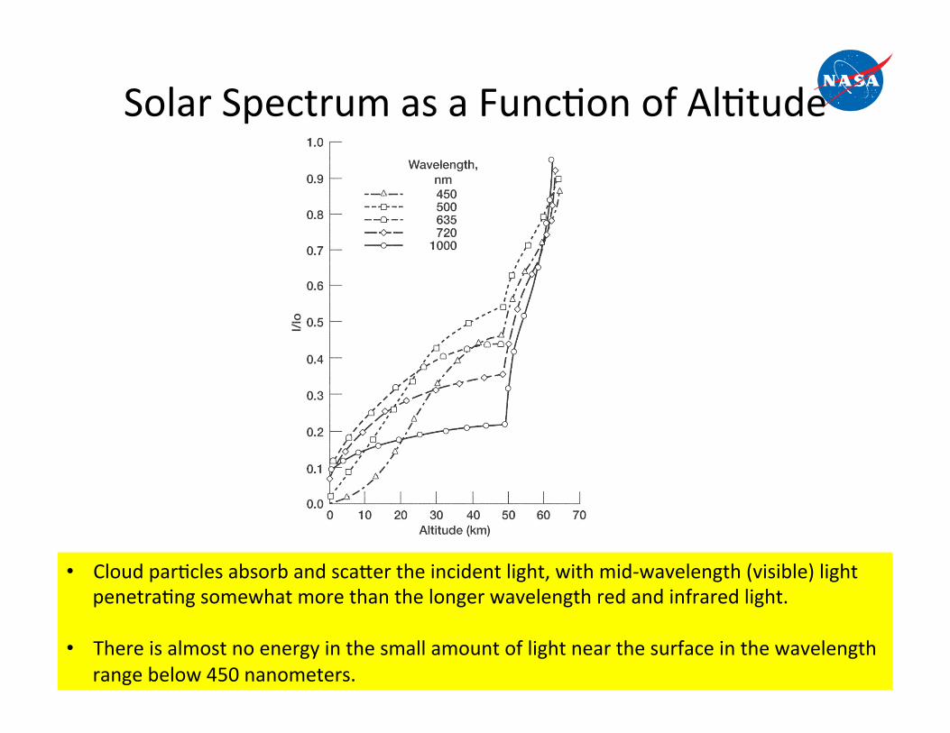
Solar Spectrum as a Func9on of Al9tude
• Cloud par9cles absorb and sca`er the incident light, with mid-‐wavelength (visible) light penetra9ng somewhat more than the longer wavelength red and infrared light.
• There is almost no energy in the small amount of light near the surface in the wavelength range below 450 nanometers.

Poten9al Power System Technologies for Future Venus Explora9on Missions

Opera9onal Envelope of Power Conversion Technologies
10 5
10 -1
10 0
10 1
10 2
10 3
10 4 El
ectr
ic P
ower
Lev
el (k
We)
1 hour 1 day 1 month 1 year 10 years
Chemical
Fission Reactors
• Fission Reactors • Solar
• Dynamic Radioisotope Generators
• Solar Solar • Static Radioisotope
Generators • Solar
Duration of Use Space missions need a variety of power solutions ( solar cells, radioisotope power sources, nuclear reactor, batteries )

SOP Technology Capabili9es
Radioisotope Power Sources
Solar Cells
Rechargeable Batteries
Power System
Power Electronics
Technology Element Capability
30-100 Wh/kg >10 years -10 to 30 C
Ni-H2
Rigid Panel 30-40 W/kg Flexible Fold Out Array : 40-100 W/kg
4-5 W/kg 6.5 % eff
GPHS RTG Si cells 9-15% eff , TJ Cells 24-28%
22- 120 V dc -55 to 75C, up to a 1Mrad > 85% converter efficiency
0.5 to 20 kW, 28- 120 V dc
Direct Energy Transfer Shunt Regulator/Radiator
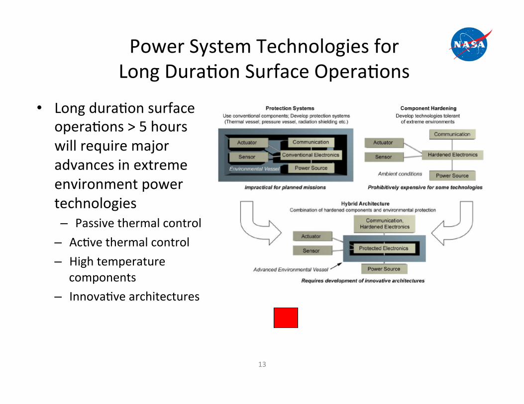
Power System Technologies for Long Dura9on Surface Opera9ons
• Long dura9on surface opera9ons > 5 hours will require major advances in extreme environment power technologies – Passive thermal control
– Ac9ve thermal control – High temperature
components – Innova9ve architectures
13

Radioisotope Power Systems for Venus Explora8on Systems

Radioisotope Thermoelectric Generators Used In Space Missions
285 We (BOM) 6.8% efficiency 5.1 We/kg 114 cm (44.9 in) long 42.7cm (16.8in) dia 56 kg (123 lb) SiGe Thermoelectrics
Galileo, Ulysses, Cassini & New Horizons
158 We (BOM) 6.6 % efficiency 4.2 We/kg 58.4 cm (23 in) long 39.7 cm (15.64 in) dia 38 kg (83.7lb) SiGe Thermoelectrics LES 8/9, Voyager 1/2
40.3 Watts (BOM) 6.2 % efficiency 3 We/kg 22.86 cm (9.0 in) long 50.8 cm (20 in) dia ~13 kg (28.6 lb) PbTe Thermoelectrics
Nimbus B-1/III, Pioneer 10/11, Viking 1/2
SiGe GPHS RTG (1980-2006)
SiGe MHW RTG (1970’s)
SNAP-19(PbTe RTG) (1960-70’s)
Limitations: Not Avaliable
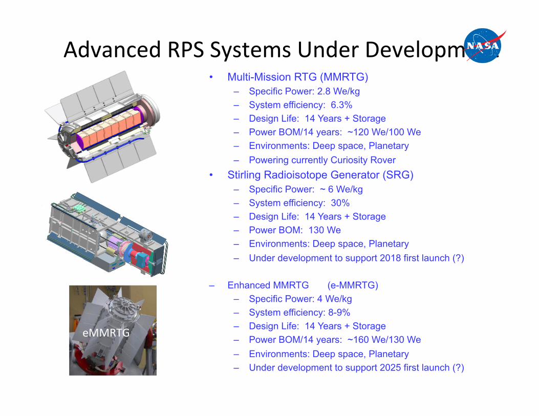
Advanced RPS Systems Under Development
3Export Controlled InformationSRG110 Quarterly 04/01/2004
SRG110 Program
• Multi-Mission RTG (MMRTG) – Specific Power: 2.8 We/kg – System efficiency: 6.3% – Design Life: 14 Years + Storage – Power BOM/14 years: ~120 We/100 We – Environments: Deep space, Planetary – Powering currently Curiosity Rover
• Stirling Radioisotope Generator (SRG) – Specific Power: ~ 6 We/kg – System efficiency: 30% – Design Life: 14 Years + Storage – Power BOM: 130 We – Environments: Deep space, Planetary – Under development to support 2018 first launch (?)
– Enhanced MMRTG (e-MMRTG) – Specific Power: 4 We/kg – System efficiency: 8-9% – Design Life: 14 Years + Storage – Power BOM/14 years: ~160 We/130 We – Environments: Deep space, Planetary – Under development to support 2025 first launch (?)
eMMRTG
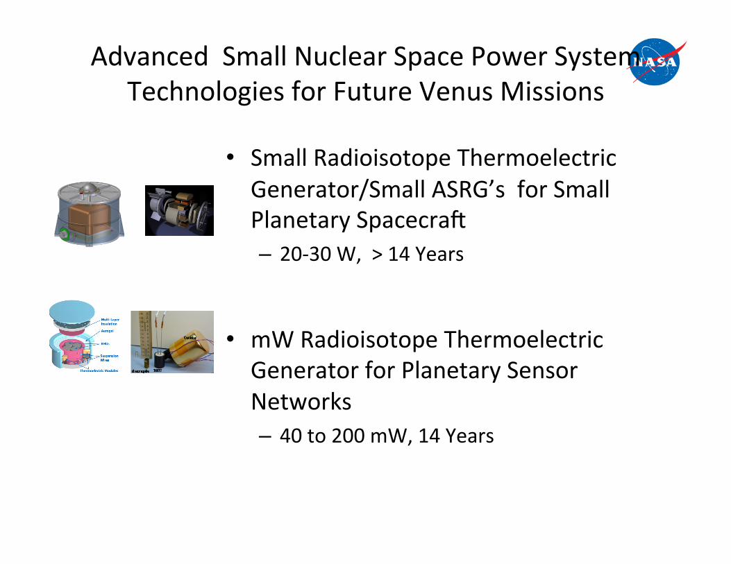
Advanced Small Nuclear Space Power System Technologies for Future Venus Missions
• Small Radioisotope Thermoelectric Generator/Small ASRG’s for Small Planetary Spacecraf – 20-‐30 W, > 14 Years
• mW Radioisotope Thermoelectric Generator for Planetary Sensor Networks – 40 to 200 mW, 14 Years
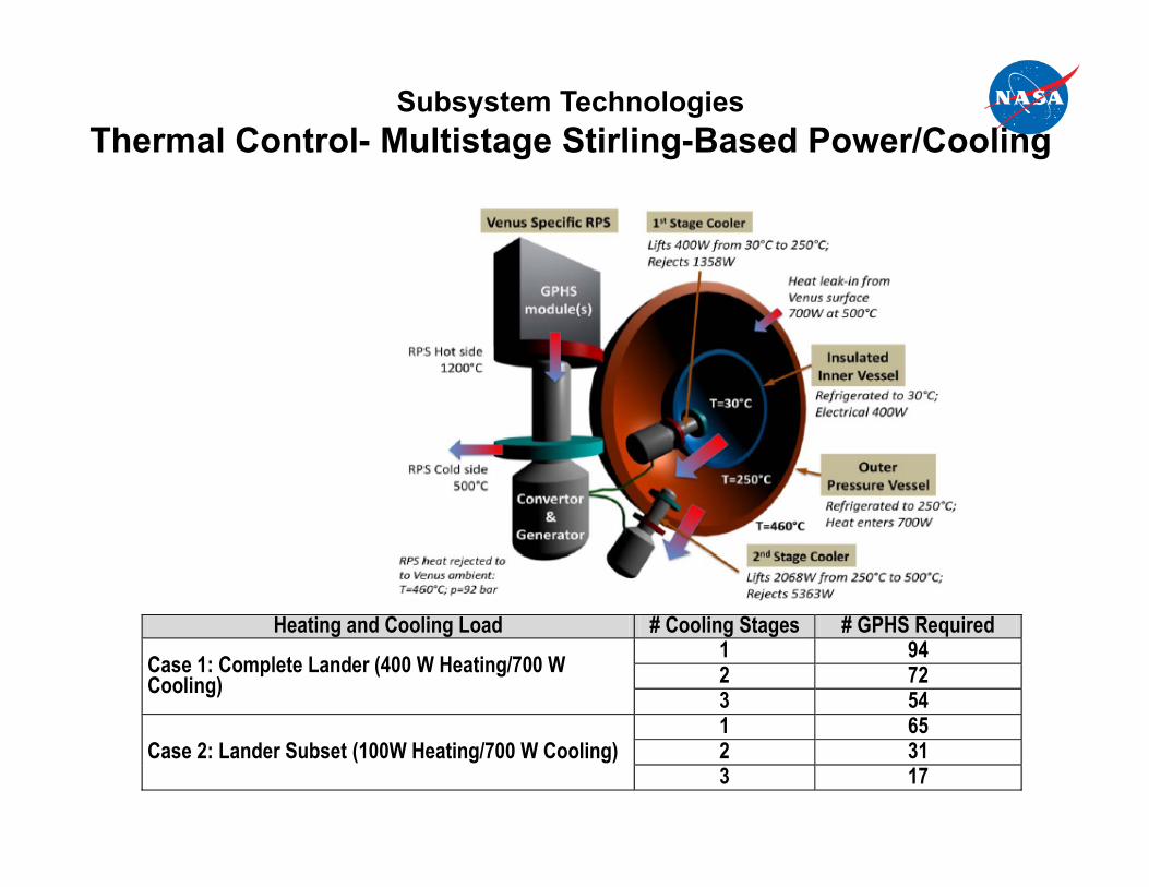
Heating and Cooling Load # Cooling Stages # GPHS Required
Case 1: Complete Lander (400 W Heating/700 W Cooling)
1 94 2 72 3 54
Case 2: Lander Subset (100W Heating/700 W Cooling) 1 65 2 31 3 17
Subsystem Technologies Thermal Control- Multistage Stirling-Based Power/Cooling

Photovoltaic Power Systems for Venus Explora8on Systems
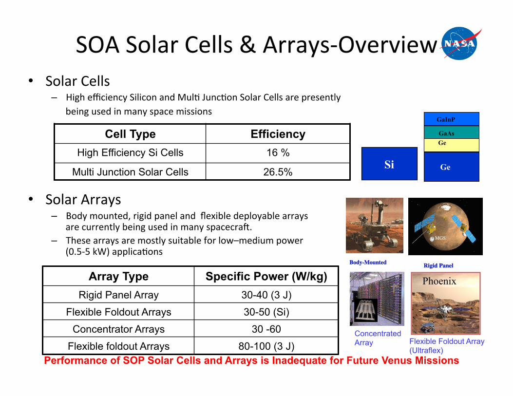
SOA Solar Cells & Arrays-‐Overview • Solar Cells
– High efficiency Silicon and Mul9 Junc9on Solar Cells are presently being used in many space missions
• Solar Arrays – Body mounted, rigid panel and flexible deployable arrays
are currently being used in many spacecraf. – These arrays are mostly suitable for low–medium power
(0.5-‐5 kW) applica9ons
Cell Type Efficiency High Efficiency Si Cells 16 %
Multi Junction Solar Cells 26.5%
Array Type Specific Power (W/kg) Rigid Panel Array 30-40 (3 J)
Flexible Foldout Arrays 30-50 (Si) Concentrator Arrays 30 -60
Flexible foldout Arrays 80-100 (3 J)
Ge
GaInP
GaAsGe
Ge
GaInP
GaAsGe
Si
Body-MountedBody-Mounted
MGS
Rigid Panel
MGSMGS
Rigid Panel
Performance of SOP Solar Cells and Arrays is Inadequate for Future Venus Missions
Concentrated Array
Phoenix
Flexible Foldout Array (Ultraflex)

Advanced Solar Cell Technologies Under Development
Low Eg Material (1.05eV)
AM0 Theoretical3-Junctions 39%4-Junctions 42%
GaAs(1.42eV)
AM0 SOLAR SPECTRUMPin =1367W/m2
Ge (0.67 eV)
Substrate
GaAs (1.42 eV)
InGaAlP (2.0 eV)
Low Eg Material (1.05eV)
AM0 Theoretical3-Junctions 39%4-Junctions 42%
GaAs(1.42eV)
AM0 SOLAR SPECTRUMPin =1367W/m2
Ge (0.67 eV)
Substrate
GaAs (1.42 eV)
InGaAlP (2.0 eV)
GaAs(1.42eV)
AM0 SOLAR SPECTRUMPin =1367W/m2
Ge (0.67 eV)
Substrate
GaAs (1.42 eV)
InGaAlP (2.0 eV)
Multi Junction Crystalline Cell
Status:34% Goal: 39%
UltraFlex
Product Performance Targets: • Specific Power*: 150-300 W/kg • Stowage volume*: 30-70 kW/m3
• Status: 100 W/kg
Mars Solar Spectrum
Substrate Thicker upper layer
Mars Solar Cells
Panel Back Side
Piezo-electric Buzzer(s)
Facesheet(.010 - .015 G/E)
Structural Spars(.040 x .30 G/E)
Panel Back Side
Piezo-electric Buzzer(s)
Facesheet(.010 - .015 G/E)
Structural Spars(.040 x .30 G/E)
Dust Accumulated
Vibratory Motion Initiated, Dust
Removal Begins
Vibratory Motion Complete
>90% Dust Removed
Dust Accumulated
Vibratory Motion Initiated, Dust
Removal Begins
Vibratory Motion Complete
>90% Dust Removed
Panel Back Side
Piezo-electric Buzzer(s)
Facesheet(.010 - .015 G/E)
Structural Spars(.040 x .30 G/E)
Panel Back Side
Piezo-electric Buzzer(s)
Facesheet(.010 - .015 G/E)
Structural Spars(.040 x .30 G/E)
Panel Back Side
Piezo-electric Buzzer(s)
Facesheet(.010 - .015 G/E)
Structural Spars(.040 x .30 G/E)
Panel Back Side
Piezo-electric Buzzer(s)
Facesheet(.010 - .015 G/E)
Structural Spars(.040 x .30 G/E)
Dust Accumulated
Vibratory Motion Initiated, Dust
Removal Begins
Vibratory Motion Complete
>90% Dust Removed
Dust Accumulated
Vibratory Motion Initiated, Dust
Removal Begins
Vibratory Motion Complete
>90% Dust Removed
Dust Accumulated
Vibratory Motion Initiated, Dust
Removal Begins
Vibratory Motion Complete
>90% Dust Removed
Dust Accumulated
Vibratory Motion Initiated, Dust
Removal Begins
Vibratory Motion Complete
>90% Dust Removed
Dust Accumulated
Vibratory Motion Initiated, Dust
Removal Begins
Vibratory Motion Complete
>90% Dust Removed
Dust Accumulated
Vibratory Motion Initiated, Dust
Removal Begins
Vibratory Motion Complete
>90% Dust Removed
Solar Array Dust Mitigation Systems

Use of TJ cells for Venus Orbital & Aerial Missions
• Commercial triple-‐junc9on solar cells con9nue to operate at temperatures of 400°C without catastrophic degrada9on [10, 11].
• The temperature of 450°C is a higher temperature than the specified opera9ng range of exis9ng adhesives used to affix cover glass to solar array.
• At the cloud level, the atmosphere contains sulfuric acid droplets. Soilar arrays need to be encapsula9on against corrosion by sulfuric acid.
• Overall, the problems of encapsula9ng, tes9ng, and qualifying the arrays for opera9on in the Venus environment has not yet been examined in detail, and many issues remain to be addressed.
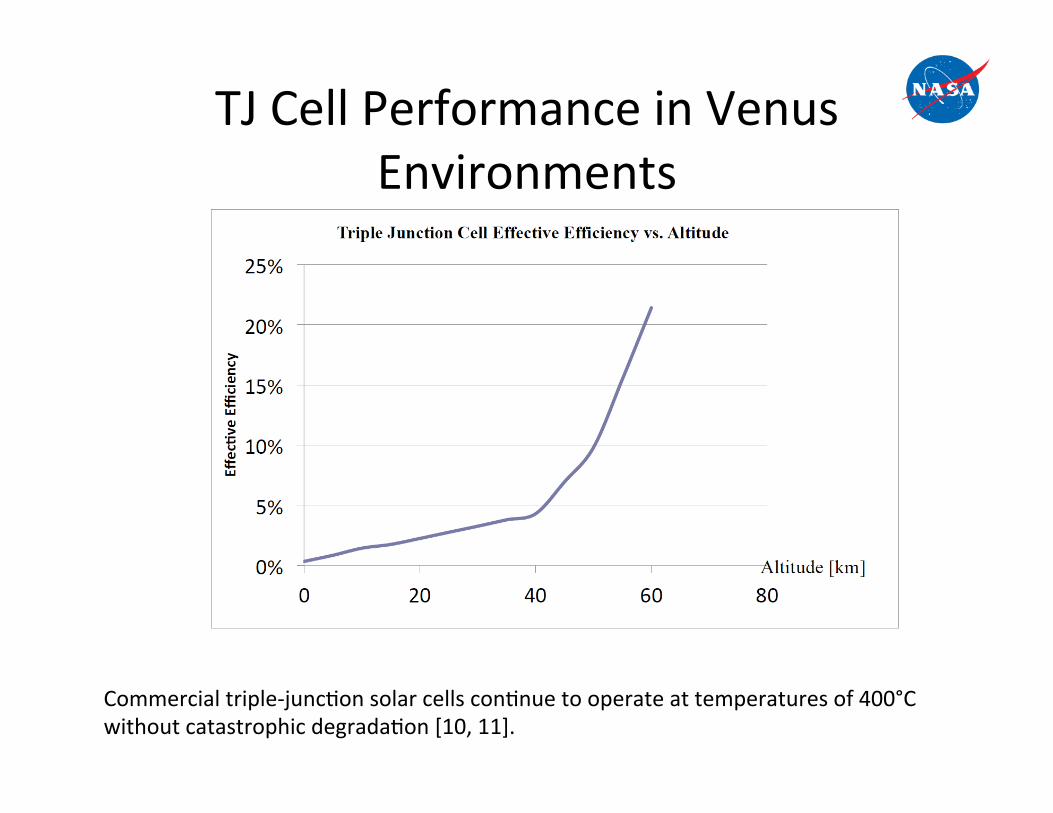
TJ Cell Performance in Venus Environments
Commercial triple-‐junc9on solar cells con9nue to operate at temperatures of 400°C without catastrophic degrada9on [10, 11].
Project Name
24
National Aeronautics and Space Administration!Jet Propulsion Laboratory!California Institute of Technology!JPL/Caltech Proprietary – Not for Public Release!!
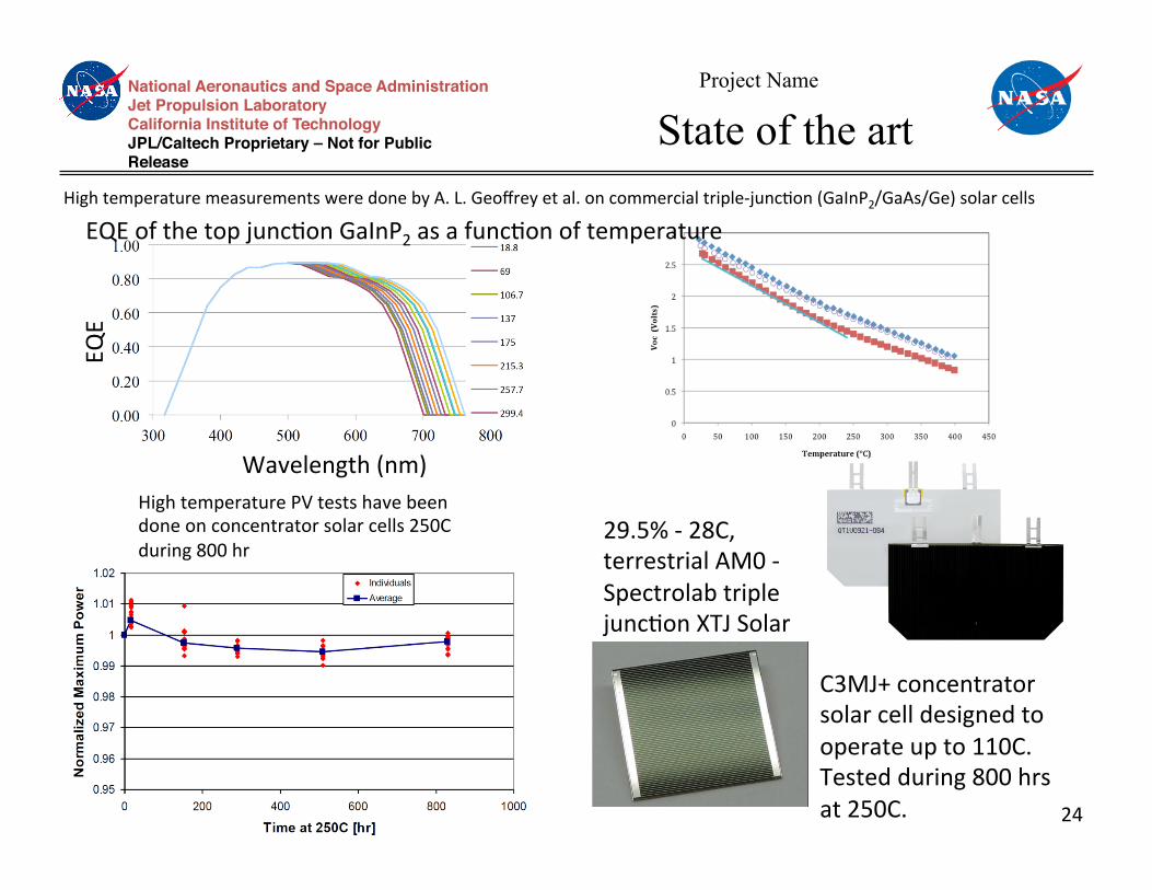
State of the art
High temperature PV tests have been done on concentrator solar cells 250C during 800 hr
High temperature measurements were done by A. L. Geoffrey et al. on commercial triple-‐junc9on (GaInP2/GaAs/Ge) solar cells
Wavelength (nm)
EQE
EQE of the top junc9on GaInP2 as a func9on of temperature
29.5% -‐ 28C, terrestrial AM0 -‐ Spectrolab triple junc9on XTJ Solar Cells
C3MJ+ concentrator solar cell designed to operate up to 110C. Tested during 800 hrs at 250C.
12/7/13 25
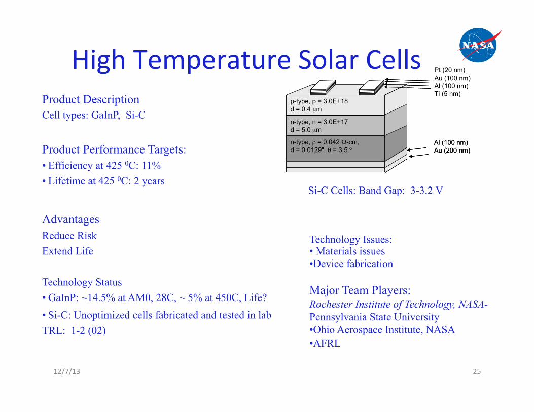
High Temperature Solar Cells Product Description Cell types: GaInP, Si-C
Product Performance Targets: • Efficiency at 425 0C: 11% • Lifetime at 425 0C: 2 years
Advantages Reduce Risk Extend Life Technology Status • GaInP: ~14.5% at AM0, 28C, ~ 5% at 450C, Life? • Si-C: Unoptimized cells fabricated and tested in lab TRL: 1-2 (02)
Technology Issues: • Materials issues • Device fabrication
Major Team Players: Rochester Institute of Technology, NASA-Pennsylvania State University • Ohio Aerospace Institute, NASA • AFRL
Cu(In,Ga)S2
Pt (20 nm)Au (100 nm)Al (100 nm)Ti (5 nm)
n-type, ρ = 0.042 Ω-cm,d = 0.0129", θ = 3.5 o
n-type, n = 3.0E+17d = 5.0 µm
p-type, p = 3.0E+18d = 0.4 µm
Al (100 nm)Au (200 nm)
Pt (20 nm)Au (100 nm)Al (100 nm)Ti (5 nm)
n-type, ρ = 0.042 Ω-cm,d = 0.0129", θ = 3.5 o
n-type, n = 3.0E+17d = 5.0 µm
p-type, p = 3.0E+18d = 0.4 µm
n-type, ρ = 0.042 Ω-cm,d = 0.0129", θ = 3.5 o
n-type, n = 3.0E+17d = 5.0 µm
p-type, p = 3.0E+18d = 0.4 µm
Al (100 nm)Au (200 nm)
Si-C Cells: Band Gap: 3-3.2 V

Project Name
26
National Aeronautics and Space Administration!Jet Propulsion Laboratory!California Institute of Technology!JPL/Caltech Proprietary – Not for Public Release!!
High temperature missions Surface missions
High temperature solar cells: CdTe – CIGS – Triple Junction Solar cell with high temperature electronic and packaging
480C at the surface of Venus. 450C at the surface of Mercury.
Orbital missions
Atmospheric missions Solar orbiter
1000C for a solar probe spacecraft.
Low Intensity High Temperature
Normal Intensity High Temperature
Venus At 30km altitude, intensity is equivalent to earth Temperature is 200C
High Intensity High Temperature
High Intensity Venus At 60km altitude, intensity twice intensity of earth Temperature is 0C
VEGA prototype test Balloon for Venus atmosphere
Solar probe flying by the sun
Rover at the surface of Venus Solar probe flying by
Venus
Normal Intensity
Standard Triple Junction Solar cells
Standard Triple Junction Solar cells with high temperature electronics
Simgle junction solar cells: CdTe – CIGS – GaAs Solar cell with high temperature electronic and packaging Resistant to radiations
Energy Storage Technologies for Future Venus Missions

12/7/13 28
Performance Envelope of Electrochemical Power Sources
C
a p
a c
i t
o r s
Service life dictates the choice of energy storage technology

SOP Energy Storage Technologies Primary Batteries Rechargeable Batteries Fuel Cells
Li-SOCl2
Li-SO2
Ni-Cd
Ni-H2
Li-Ion
PEM
PEM
Alkaline
Ag-Zn Battery

Characteris9cs of SOP Primary Ba`eries
12/7/13 30
Limitations • Moderate specific energy (100-250 Wh/kg) • Limited operating temp range (-40 C to 70oC) • Radiation tolerance poorly understood • Voltage delay
Type Application Mission Specific
Energy, Wh/kg (b)
Energy Density, Wh/l
(b)
Operating Temp.
Range, °C
Mission Life (yrs)
Issues
Cell 238 375 -40 to 70 <10
Li-SO2 Battery
Galileo Probe Genesis SRC MER Lander Stardust SRC
90-150 130-180 -20 to 60 9 Voltage Delay
Cell 390 878 -30 to- 60 >5
Li-SOCl2 Battery
Sojourner Deep Impact DS-2 Centaur Launch batteries
200-250 380-500 -20 to 30 < 5 Severe voltage
delay
Li-CFx Cell 614 1051 -20 to 60 Poor power capability
12/7/13 31
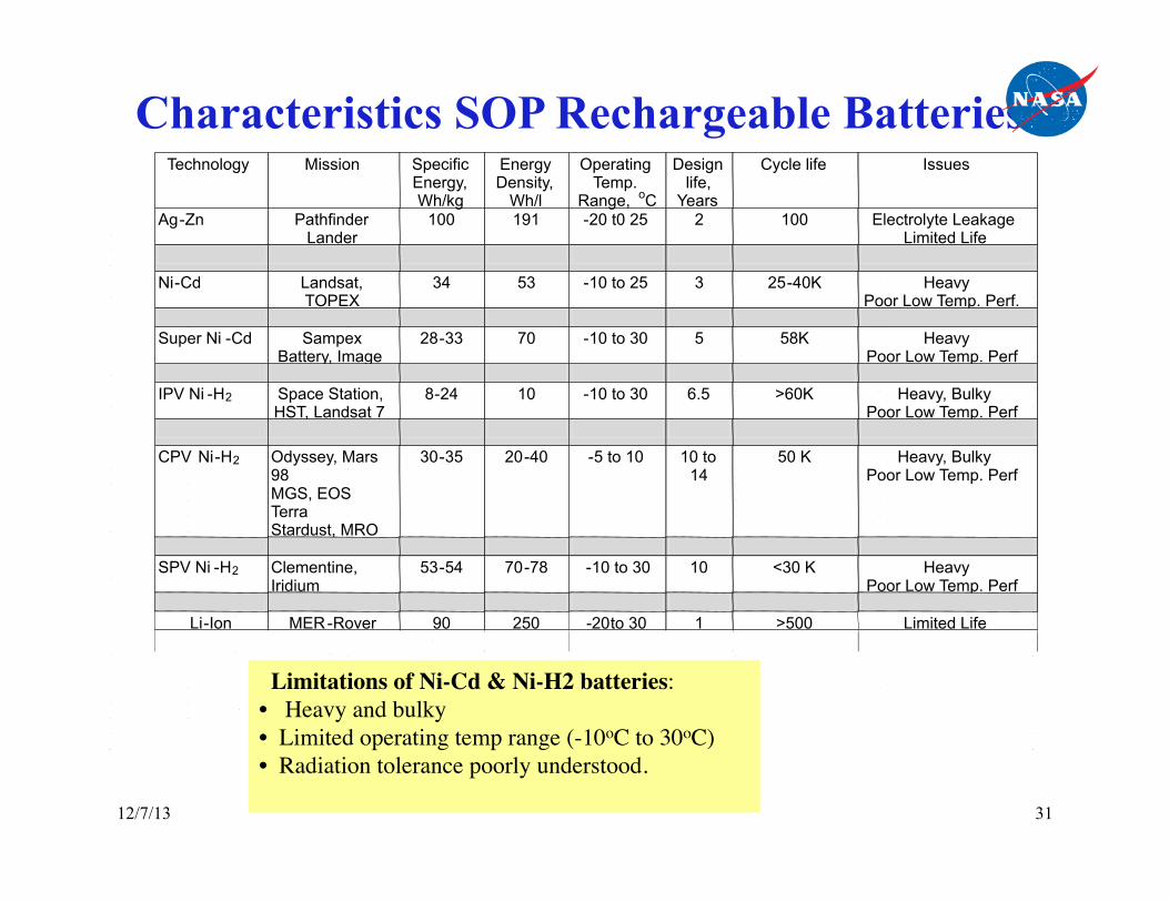
Characteristics SOP Rechargeable Batteries
Limitations of Ni-Cd & Ni-H2 batteries: • Heavy and bulky • Limited operating temp range (-10oC to 30oC) • Radiation tolerance poorly understood.
Technology Mission Specific Energy, Wh/kg
Energy Density,
Wh/l
Operating Temp.
Range, o C
Design life,
Years
Cycle life Issues
Ag - Zn Pathfinder Lander
100 191 - 20 t0 25 2 100 Electrolyte Leakage Limited Life
Ni - Cd Landsat,
TOPEX 34 53 - 10 to 25 3 25 - 40K Heavy
Poor Low Temp. Perf. Super Ni - Cd Sampex
Battery, Image 28 - 33 70 - 10 to 30 5 58K Heavy
Poor Low Temp. Perf IPV Ni - H 2 Space Station,
HST, Landsat 7 8 - 24 10 - 10 to 30 6.5 >60K Heavy, Bulky
Poor Low Temp. Perf CPV Ni - H 2 Odyssey, Mars
98 MGS, EOS Terra Stardust, MRO
30 - 35 20 - 40 - 5 to 10 10 to 14
50 K Heavy, Bulky Poor Low Temp. Perf
SPV Ni - H 2 Clementine,
Iridium 53 - 54 70 - 78 - 10 to 30 10 <30 K Heavy
Poor Low Temp. Perf
Li - Ion MER - Rover 90 250 -20 to 30 1 >500 Limited Life

12/7/13 32
High Temperature Ba`eries Technology Status • Three types of chemistries: Na-‐S, Na-‐ MCl2,, Li-‐FeS2
– Operate at > 400o C. Developed ini9ally for EV applica9ons(1980’s). TRL 3
– No work is presently in progress on these ba`eries afer the inven9on of Li-‐Ion ba`eries.
• Li-‐FeS2 thermal ba`eries are in use for pyro firing applica9ons • No high energy density primary ba`eries exist • New Concepts: Li-‐CoS2, Li-‐CO2 , TRL 1
Advantages High Temperature opera9on
Mission Applica8ons • Inner planetary surface missions (High temp) Technical Issues
• Seals • Safety • Zero gravity effects Current programs • None
Potential Capabilities Characteristic SOA Adv. HT Battery
Operating Temp Range, °C 400 475 Specific Energy for Batteries, Wh/kg
100 150
Cycle Life, cycles >100 > 500
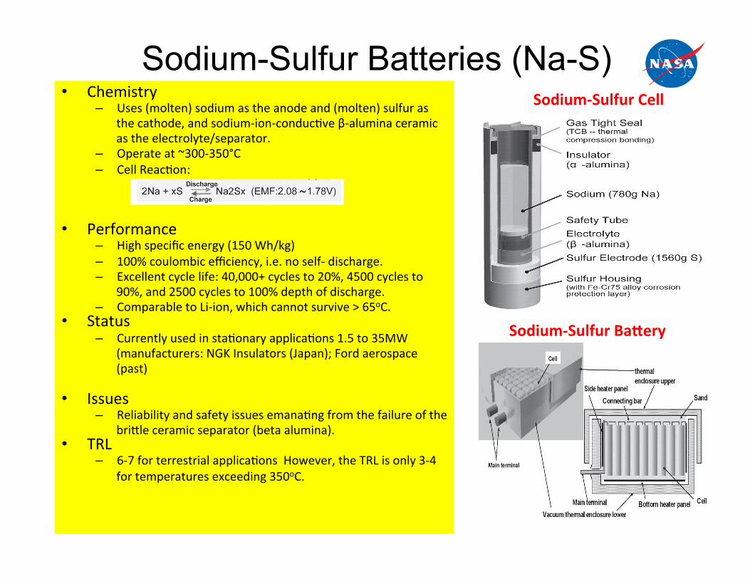
Sodium-Sulfur Batteries (Na-S) • Chemistry
– Uses (molten) sodium as the anode and (molten) sulfur as the cathode, and sodium-‐ion-‐conduc9ve β-‐alumina ceramic as the electrolyte/separator.
– Operate at ~300-‐350°C – Cell Reac9on:
• Performance – High specific energy (150 Wh/kg) – 100% coulombic efficiency, i.e. no self-‐ discharge. – Excellent cycle life: 40,000+ cycles to 20%, 4500 cycles to
90%, and 2500 cycles to 100% depth of discharge. – Comparable to Li-‐ion, which cannot survive > 65oC.
• Status – Currently used in sta9onary applica9ons 1.5 to 35MW
(manufacturers: NGK Insulators (Japan); Ford aerospace (past)
• Issues – Reliability and safety issues emana9ng from the failure of the
bri`le ceramic separator (beta alumina). • TRL
– 6-‐7 for terrestrial applica9ons However, the TRL is only 3-‐4 for temperatures exceeding 350oC.
Development of Sodium-Sulfur Batterieswww.ceramics.org/ACT 271
with the positive electrode in the center is also conceiv-able. However, a design with the positive electrode in theperiphery and the negative electrode in the center pro-vides higher energy density since the positive electroderequires a significantly larger volume than the negativeelectrode.
For both safety and performance reasons, a high-in-tegrity seal between the electrodes is essential. The openend of the E-alumina tube is capped with a disk consist-ing of an D-alumina (Al2O3) ring joined to borosilicateglass that insulates the electrodes. Aluminum electrodeterminals are joined to the D-alumina ring by thermalcompression. The E-alumina electrolyte and D-aluminaring electrically isolate the active materials of the two elec-trodes, and the cell is hermetically sealed by the thermalcompression fitting between the D-alumina ring and thealuminum casing surrounding the positive (S) electrode.Also, a protective coating (plasma sprayed Fe-75Cr alloy)to resist corrosion by sulfur and sodium polysulfide isapplied to the inner wall of the sulfur electrode alumi-num casing.
NAS battery cells are configured in series and paral-lel to provide the specified voltage and energy, and en-closed within a thermally insulated enclosure to form aNAS battery module as illustrated in Fig. 5. The spacebetween cells is filled with sand, which acts as both an
insulator and a means of lateral support. Cell tempera-tures are maintained at about 300°C by a combination ofelectric heaters located within the enclosures and naturalair convection over the outside to reject excess heat. Thethermal design of the module is optimized so that heatgenerated during daily charging and discharging main-tains the operating temperature regime under most am-bient conditions.
NAS BNAS BNAS BNAS BNAS Batteratteratteratterattery Fy Fy Fy Fy Featureatureatureatureatureseseseses
Key features of NAS batteries include:· High energy density with corresponding reductions
in space required for battery installations, i.e., aboutone-third the space required for lead-acid batteriesin similar commercial applications.
· 100% coulombic efficiency, i.e., there is no self-discharge.
· 85+% average DC conversion efficiency, i.e., thereare no intermediate reactions and the electrical re-sistance of the E-alumina solid electrolyte prohib-its the internal flow of electrons between electrodes.(This value does not include energy losses for con-version to AC power (~8%) or to maintain thebattery operating temperature, which is very smallin daily cycling applications.)
· High cycle life, e.g., NAS batteries are capable of40,000+ cycles to 20%, 4500 cycles to 90%, and2500 cycles to 100% depth of discharge (DOD).(These values are about a factor of 4 better thanhigh-quality commercial lead-acid batteries.)
· No barriers to high volume, low cost production,i.e., sodium and sulfur are abundant materials, ce-ramic component manufacturing has been verified,and fabrication of integrated modules has beenautomated.
Fig. 4. NAS battery cell.
Fig. 5. NAS battery module.
Oshima.p65 6/16/2004, 11:12 PM71
270 Vol. 1, No. 3, 2004International Journal of Applied Ceramic Technology�Oshima, Kajita, and Okuno
through the E-alumina electrolyte to the positive elec-trode where they react with sulfur to form sodium polysul-fide. When a cell is charged, this reaction is reversed, i.e.,the sodium polysulfide at the positive electrode decom-poses, and sodium ions return to the positive electrode.Within the battery industry, batteries that are capable ofbeing repeatedly discharged and charged through revers-ible electrochemical reactions are termed “secondary” bat-teries, as opposed to “primary” batteries which cannot berecharged.
The composition of the sodium polysulfide (Na2Sx)that forms at the positive electrode changes with the state-of-charge. Fig. 2 is a phase diagram for the Na2Sx series,and Fig. 3 shows the relation between the electromotiveforce and the state-of-charge. The changing compositionof sodium polysulfide is indicated by the number of Satoms, i.e., by the value of “x” in the expression, Na2Sx.At a high state-of-charge, in which the electromotive forceis essentially constant and the temperature is near 300°C,the S (positive) electrode consists of co-existing phases ofboth S and Na2S5. As the cell is discharged, all S com-bines with Na to form a single-phase region with onlyNa2Sx, in which “x” is less than 5. In this region, the rela-tionship between state-of-charge and electromotive forceis essentially linear as “x” decreases. With still further dis-charging, a solid phase with a high melting point formsas “x” approaches 2 (Na2S2). At this point, increased resis-tance at the positive electrode prohibits further discharge.
The ConfigurThe ConfigurThe ConfigurThe ConfigurThe Configuration of NAS Bation of NAS Bation of NAS Bation of NAS Bation of NAS Batteratteratteratterattery Cy Cy Cy Cy Cellsellsellsellsells
Fig. 4 is an illustration of NGK’s NAS battery cell.The cell is cylindrical with sodium (the negative electrode)
in the center and sulfur (the positive electrode) located inan annulus, separated from the negative electrode by theE-alumina solid electrolyte. The E-alumina electrolyte isin the form of a tube with the bottom end closed. Theo-retically, E-alumina electrolyte could be configured as aflat plate; however, strength and fabricability issues limitpractical designs to cylindrical shapes. A configuration
Fig. 1. NAS battery cell principle of operation.
Fig. 2. Na2Sx phase diagram.
Fig. 3. NAS cell voltage vs. state-of-charge (note changingcomposition of the sulfur electrode).
Oshima.p65 6/16/2004, 11:11 PM70
Sodium-‐Sulfur Cell
Sodium-‐Sulfur BaEery

Sodium-Metal Chloride Batteries (Na-MCl2) • Chemistry
– Uses (molten) sodium as the anode and solid metal chloride (iron or nickel) as cathode in sodium tetrachloro-‐aluminate melt and with Na+-‐ion-‐conduc9ve β-‐alumina ceramic as the separator electrolyte.
– Operate at ~300-‐400°C – Cell Reac9on:
2.6 V
• Performance
– Specific energy: 115 Wh/kg; Energy density: 160 Wh/L – Cycle Life: > 2000 cycles at 100% DOD and >3,000 cycles
at 80% DOD. – Safer and more reliable than Na-‐S – Can be operated at higher temperatures (Venus: 475oC)
due to the low vapor pressure of the molten salt. – Comparable to Li-‐ion, which cannot survive > 65oC.
• Status – Currently used in sta9onary applica9ons 1.5 to 35MW
(manufacturers: NGK Insulators (Japan); Ford aerospace (past)
• Issues – Reliability and safety emana9ng from the failure of the
ceramic separator (beta alumina). • TRL
– 6-‐7 for terrestrial applica9ons However, The TRL is 3-‐4 for temperatures exceeding 350oC.
Planar Sodium-‐ Nickel Chloride Cell
oxygen ions from the packing ȕ"-Al2O3 powders to the samples. The phase structures of the as-sintered and converted samples were determined by powder X-ray diffraction (XRD). The microstructures of the samples were observed using scanning electron microscope (SEM) equipped with an energy-dispersive X-ray spectroscope (EDS) and sodium ion distribution across the BASE was examined with SEM/EDS as well. The achieved ȕ"-Al2O3 discs had a thickness of 1 mm. The packing ȕ"-Al2O3 powders were synthesized using starting precursors of boehmite, Na2CO3 and Li2CO3 via solid-state reaction (16,17). Single Cell Construction and Testing The single cell was schematically shown in Figure 1. The converted ȕ"-Al2O3 disc with the diameter of 26 mm was glass-sealed to an outer thicker Į-Al2O3 ring. The cell was then moved into a glove box and assembled in a discharged state with starting powders consisting of Ni, NaCl and small amounts of additives. The powders with the amount of 2g were thoroughly mixed and granulated. The granulate was then poured into cathode compartment. After a final drying treatment to get rid of all traces of moisture, molten NaAlCl4 was vacuum-infiltrated into the granulate at 250°C. A Ni mesh and wire was imbedded into the cathode as current collector. At the anode side, a metal shim was inserted into the anode compartment and copper wool filled the gap between the electrolyte and shim. Anode and cathode end plates were then compressed to the Į-Al2O3 ring with the help of alumina washers, as shown in Figure 1. Platinum leads were welded to the electrode end plates as current collector. The effective cell area was 3 cm2. The assembled cell was placed in a furnace inside the glove box and cell testing was carried out using an electrochemical interface (Solatron 1470E, Solartron Analytical) at 300°C. A constant current of 10 mA was used for initial five charge/discharge cycles. After cell performance was stabilized, it was further cycled at a higher rate (e.g., C/3). A low current rejuvenation process was employed for each ten higher current cycles to recover the cell performance. Microstructure of the cathode after long-term cycling was analyzed using SEM/EDS to evaluate its contribution to the cell performance degradation.
Figure 1. Schematic of a sodium-nickel chloride cell with planar design.
+
0.5
Na
Cathode/NaAlCl4
Cu wool
Ni mesh
Metal shim
Al washerȕ"-alumina electrolyte
Cathode end plate
Anode end plate
Į-alumina ring
-
ECS Transactions, 28 (22) 7-13 (2010)
9 ecsdl.org/site/terms_use address. Redistribution subject to ECS license or copyright; see 75.84.172.251Downloaded on 2013-11-12 to IP
Sodium-‐ Nickel Chloride Cell
Development of a Ni,NiCI2 Positive Electrode for a Liquid Sodium (ZEBRA) Battery Cell
R. J. Bones, D. A. Teagle, S. D. Brooker, and F. L. Cullen Harwell Laboratory, Didcot, Oxfordshire, England, 0 X l i ORA
ABSTRACT
Medium-temperature liquid sodium (ZEBRA) battery cells, employing solid transition metal dichloride cathodes, are under active development. This paper details key aspects of the development of a Ni, NiC12 positive electrode, operating in NaA1C14 molten salt electrolyte. Cells using these materials have achieved a high degree of reversibility and long cell life (>2000 cycles) and operate over the temperature range 200~176 The cell has an open-circuit voltage of 2.58V at 300~ and is an attractive contender for use in high-energy and power density advanced batteries. Mention is made to the related Fe-based electrode.
Medium-temperature liquid sodium ZEBRA battery cells employing solid transition metal dichloride cathodes (positive electrodes) are under active development (1-4). This paper discusses key aspects of the development of the Ni, NiC12 cathode option in this family of cells. Figure 1 shows a schematic diagram of the cell in the charged state and gives the cell reaction; the solid cathode operates in a basic NaA1C14 molten salt electrolyte in which both NiC12 and NaC1 are effectively insoluble.
The open-circuit voltage of the cell at 250~ is 2.59V, an 0.24V advantage over the related cell with an Fe,FeC12 cathode at the same temperature. It is customary to oper- ate the Na/Ni,NiC12 cells at 300~176 where the combina- tion of a lower beta"-alumina resistance and the high OCV (2.58V at 300~ results in this cell being suitable for high- power applications.
A companion paper (5) deals with cell and battery devel- opment. In the present paper, emphasis is placed on the scientific aspects of the cathode operation. A significant difference exists between the NiC12-based cathode and the FeC12 electrode during cell operation in that intermediate phases have been observed between NaC1 and FeCI= in the case of the Na/FeC12 cell (6, 7).
A battery based on the sodium/Ni, NiCI= cell is a very at- tractive option, especially for high-power applications, be- cause of its high voltage and ability to operate reversibly over a wide temperature range.
Experimental The positive electrodes are conveniently assembled in
the discharged state by cosintering Ni and NaC1 powders;
T~Jna
T:200-350~
OCV = 2.59 V (at 250~
)dium
Cell reaction: NiClz § 2No ~ 2 N o C I + N i CHARGED STATE DISCHARGED STATE
Fig. 1. Schematic diagram of sodium/nickel II chloride battery cell
the porosity structure of the cathode is determined by pre- selecting the particle size distribution in the components. The ratio of NaCI:Ni for this series of experiments was such that when fully charged, 30% of the Ni metal was con- verted to NiC12.
The published NiC12-NaC1 phase diagram (8) is shown in Fig. 2a. It can be seen that within the indicated tempera- ture range of operation, two phases exist in equilibrium; this has been confirmed in practice both by x-ray diffrac- tion of partially charged cathodes and by accurate cou- lometric titrations at 250~176 Figure 2b shows the con- stant OCV throughout the first charge and discharge cycle---this is retained throughout the life of the cell. The charge and discharge curves shown are at low rates, 10 mA cm -2 and 20 m A c m -2, respectively.
SEM examination (Fig. 3) of a partially charged NiC12 cathode, previously operating at 300~ clearly shows the
O
1000 , , ,
600
200
OI I ~ I I 100 75 50 25 0
NiCI 2 2NoCI MOLE %
2'8
U3 t-- - 2-6 O >
-- 2- / . - LU
1.58
0 FULL CHARGE
,/INITIAL CHARGE (0"5A}
-O-C-V7 ~FIRST DISCHARGE'~" ',
el.OAf \ , , i
I I I I I 20 40 60 80 100 FULL DISCHARGE
% THEORETICAL CAPACITY Fig. 2. (a, top) Phase diagram of NiCI2/NaCI system. (b, bottom) First
complete cycle of Na/NiCIz cell (assembled in the discharged state).
1274 J. Electrochem. Sac., Vol. 136, No. 5, May 1989 9 The Electrochemical Society, Inc. ecsdl.org/site/terms_use address. Redistribution subject to ECS license or copyright; see 137.79.61.169Downloaded on 2013-11-13 to IP
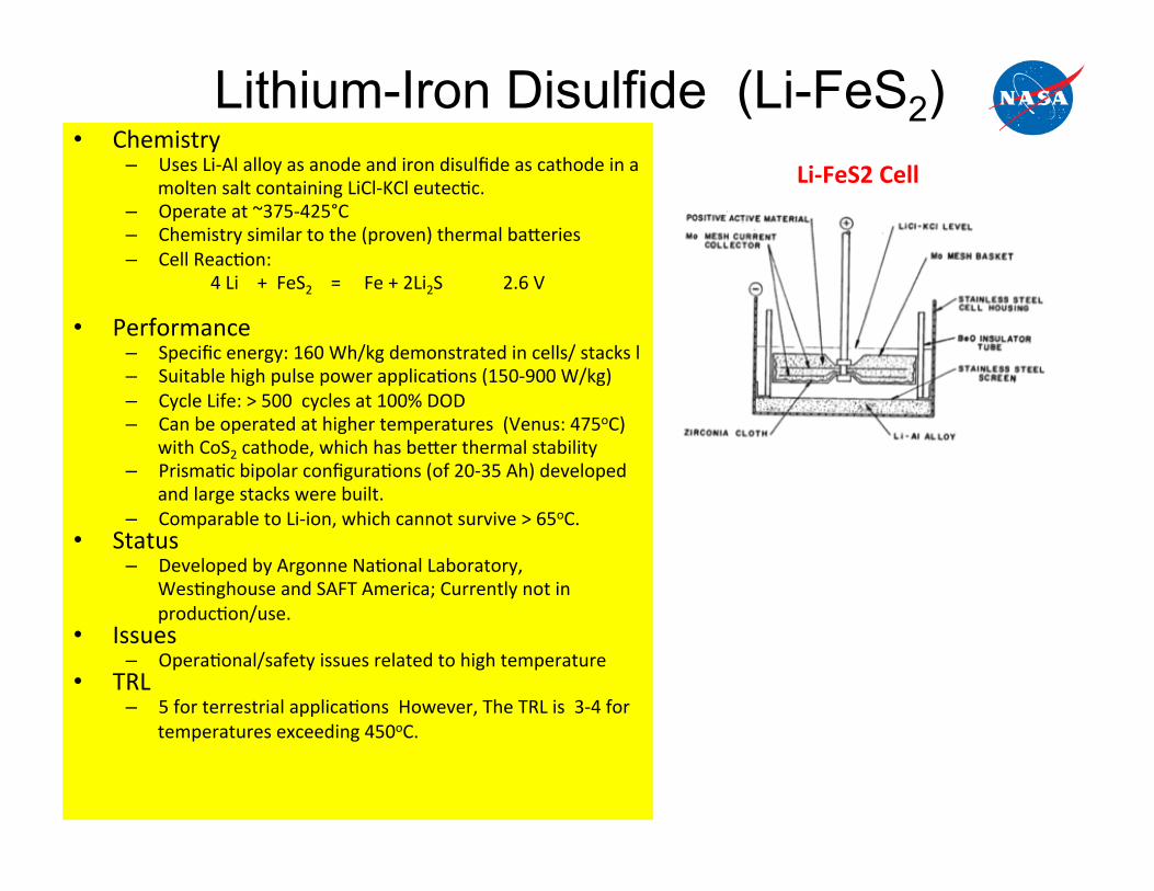
Lithium-Iron Disulfide (Li-FeS2) • Chemistry
– Uses Li-‐Al alloy as anode and iron disulfide as cathode in a molten salt containing LiCl-‐KCl eutec9c.
– Operate at ~375-‐425°C – Chemistry similar to the (proven) thermal ba`eries – Cell Reac9on:
4 Li + FeS2 = Fe + 2Li2S 2.6 V
• Performance – Specific energy: 160 Wh/kg demonstrated in cells/ stacks l – Suitable high pulse power applica9ons (150-‐900 W/kg) – Cycle Life: > 500 cycles at 100% DOD – Can be operated at higher temperatures (Venus: 475oC)
with CoS2 cathode, which has be`er thermal stability – Prisma9c bipolar configura9ons (of 20-‐35 Ah) developed
and large stacks were built. – Comparable to Li-‐ion, which cannot survive > 65oC.
• Status – Developed by Argonne Na9onal Laboratory,
Wes9nghouse and SAFT America; Currently not in produc9on/use.
• Issues – Opera9onal/safety issues related to high temperature
• TRL – 5 for terrestrial applica9ons However, The TRL is 3-‐4 for
temperatures exceeding 450oC.
Li-‐FeS2 Cell
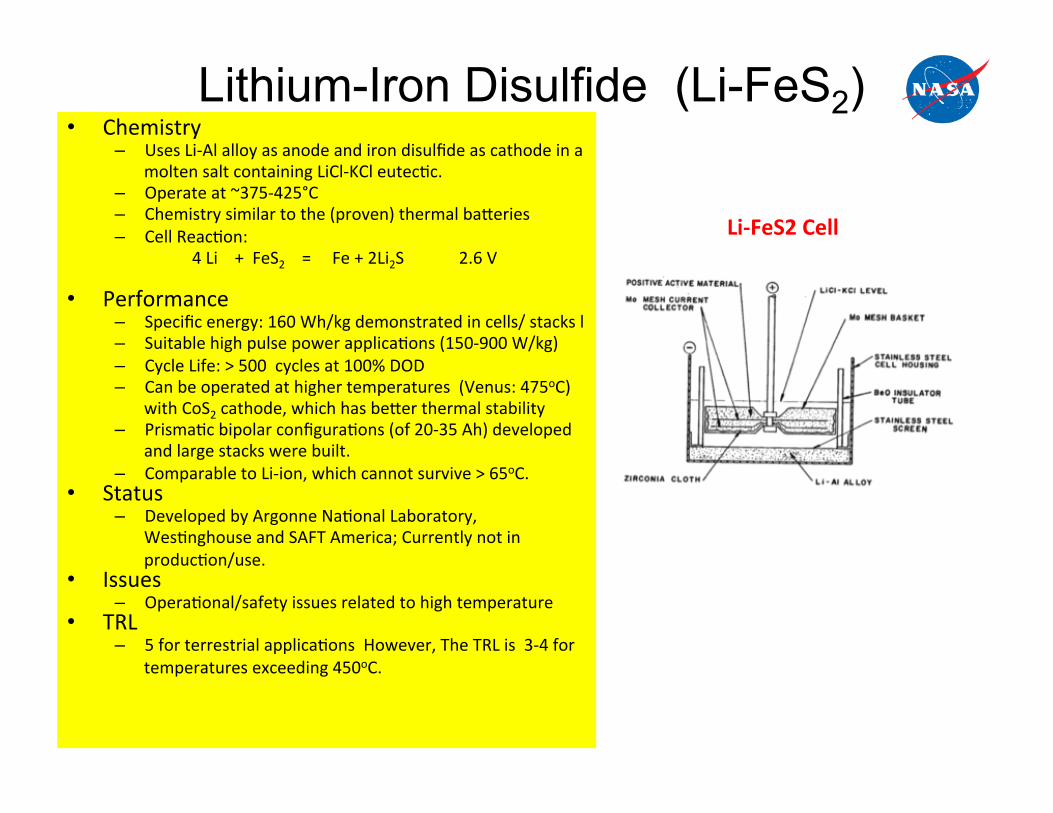
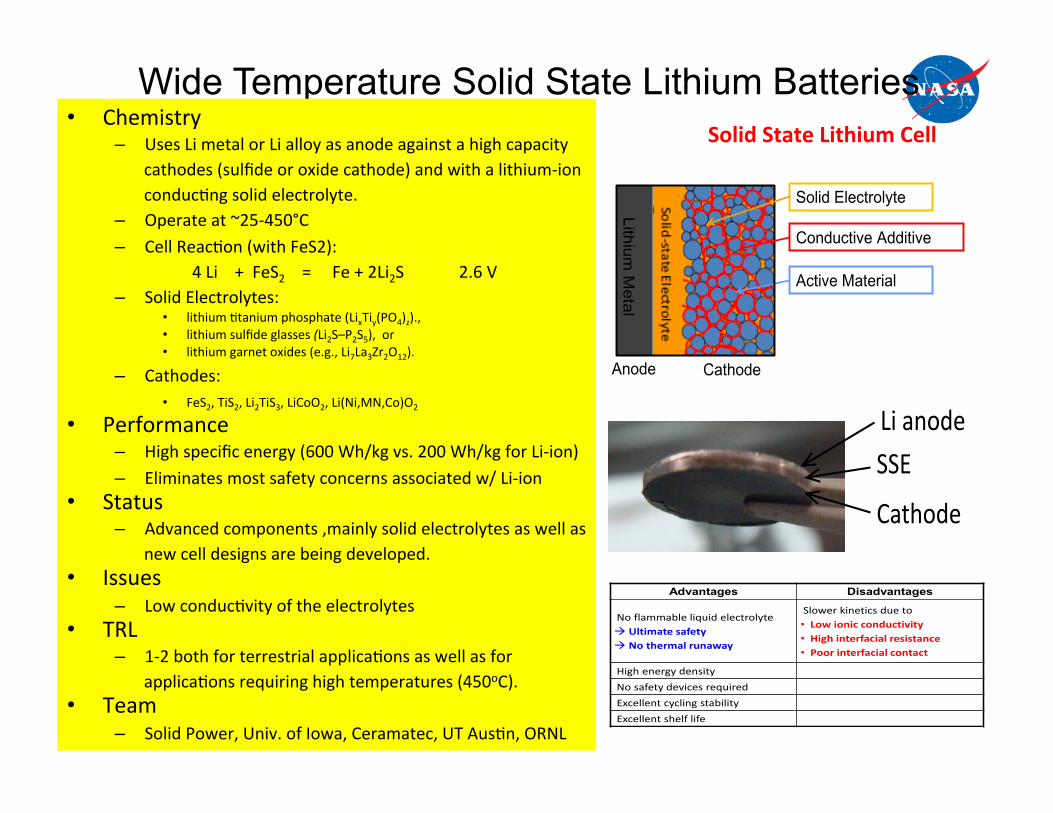
Wide Temperature Solid State Lithium Batteries • Chemistry
– Uses Li metal or Li alloy as anode against a high capacity cathodes (sulfide or oxide cathode) and with a lithium-‐ion conduc9ng solid electrolyte.
– Operate at ~25-‐450°C – Cell Reac9on (with FeS2):
4 Li + FeS2 = Fe + 2Li2S 2.6 V – Solid Electrolytes:
• lithium 9tanium phosphate (LixTiy(PO4)z)., • lithium sulfide glasses (Li2S–P2S5), or • lithium garnet oxides (e.g., Li7La3Zr2O12).
– Cathodes: • FeS2, TiS2, Li2TiS3, LiCoO2, Li(Ni,MN,Co)O2
• Performance – High specific energy (600 Wh/kg vs. 200 Wh/kg for Li-‐ion) – Eliminates most safety concerns associated w/ Li-‐ion
• Status – Advanced components ,mainly solid electrolytes as well as
new cell designs are being developed. • Issues
– Low conduc9vity of the electrolytes • TRL
– 1-‐2 both for terrestrial applica9ons as well as for applica9ons requiring high temperatures (450oC).
• Team – Solid Power, Univ. of Iowa, Ceramatec, UT Aus9n, ORNL
Solid State Lithium Cell
Why solid state battery?
? Advantages Disadvantages
No flammable liquid electrolyte Æ Ultimate safety Æ No thermal runaway
Slower kinetics due to • Low ionic conductivity • High interfacial resistance • Poor interfacial contact
High energy density
No safety devices required
Excellent cycling stability
Excellent shelf life 3
General Solid State Battery Construction
Two electrodes are separated by solid state electrolyte layer
– Electrolyte has high ionic conductivity and is electronically insulating Composite electrodes
– Incorporate solid electrolyte into composite for fast ion transport – Incorporate conductive additive into composite for fast electron transport
Anode Cathode
Lithium M
etal
Active Material
Conductive Additive
Solid Electrolyte
4
Cathode
SSE
Li anode

Summary & Conclusions
• Venus environment poses significant challenges for power systems
• SOP power system technologies (with some modifica9ons)could be used for orbital missions with
• SOP power system technologies have limited opera9onal capability for long dura9on Venus aerial and surface missions.
• SOP power system technologies can be used with some engineering modifica9ons for short dura9on Venus aerial and surface missions.
• Some of the terrestrial power system technologies could be adopted with moderate funding.
• Currently no funding is available for the development of power system technologies for Venus missions.

Backup Slides

Project Name
40
National Aeronautics and Space Administration!Jet Propulsion Laboratory!California Institute of Technology!JPL/Caltech Proprietary – Not for Public Release!!
Degradation mechanism We need to iden9fy the cause of solar cell degrada9on under extreme environment
Venus environment challenges for photovoltaic cells: 1. Solar intensity 2. Solar spectrum 3. Temperature. 4. Corrosive environment
An SEM micrograph of a circuit that failed due to electromigra9on and a schema9c illustra9ng the influence of temperature and current density on electromigra9on. Extreme Environment
Electronics, Industrial Electronics, CRC Press (2012)

Characteris8cs of Space Fuel cells
0
50
100
150
200
250
300
Gemini 1962-1968 Apollo 1966-1978 Shuttle, 1981-current Future ProgramsMissions
Spec
ific
Pow
er, W
/kg
Early PEM Fuel Cell
Alkaline Fuel Cell
Gen II Alkaline Fuel Cell
Advanced PEM Fuel Cell(Proposed)

High Temperature Batteries for Venus Missions