
PowerPoint Presentation · FIR polarimeter array Optical access Inner surface B-dot array...
20
CONFIDENTIAL R. Ivanov, W. Young, P. Carle, A. Froese, K. Epp EPR 2017 S. Howard, M. Laberge, M. Reynolds, P. O’Shea,
Transcript of PowerPoint Presentation · FIR polarimeter array Optical access Inner surface B-dot array...
CONFIDENTIAL
R. Ivanov, W. Young, P. Carle, A. Froese, K. Epp
EPR 2017
S. Howard, M. Laberge, M. Reynolds, P. O’Shea,
2
PI3
1 m
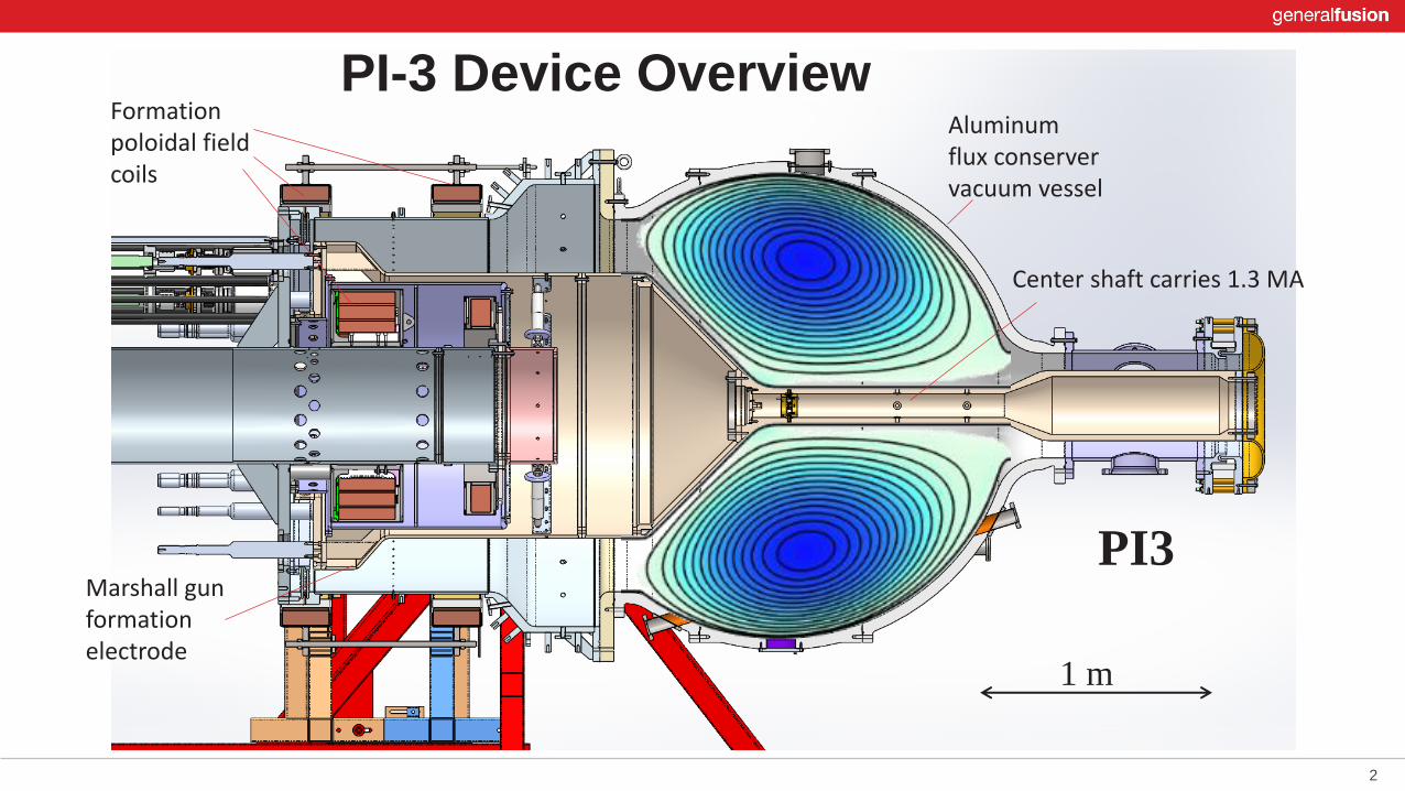
PI-3 Device OverviewFormation poloidal field coils
Marshall gun formation electrode
Center shaft carries 1.3 MA
Aluminum flux conserver vacuum vessel

3
3D MHD simulation (VAC) of ST formation process.
Shows evolution of l = m0 J||/B.
Shaft current of 1.2 MA rising to 1.3 MA.Plasma current of 750 kA falling to 500 kA
Negative l regions (blue) exist in this simulation that causes plasma to stay small.
Steep gradients go unstable and it reorganizes into a larger object with less hollow profiles, q becomes >1.
Fast CHI Formation into Pre-Existing Toroidal Field

4
Parameter Value range
Vessel inner radius 1 m
Major radius R 0.6 – 0.7 m
Minor radius a 0.3 – 0.4 m
Elongation k 1 – 1.6
Triangularity d -0.15 – +0.1
Poloidal flux YCT 0.15 – 0.3 Wb
Plasma current Ip 0.3 – 0.6 MA
Shaft current Is 1.0 – 1.3 MA
Plasma density ne 2x10¹⁹ – 2x10²⁰ m-3
Temperature Te ~ Ti 100 – 500 eV
Beta b 2% - 8 %
PI-3
1 m
Basic Parameters

5
PI-1 and PI-2 were 2-stage coaxial Marshall gun/railgun accelerator systems producing spheromak plasmas.
They explored:
The accelerating railgun electrodes were conically converging to achieve the 4x radial compression to bridge
the gap between the densities achievable with Marshall gun formation, and what was required for the initial state
of the proposed MTF compression scenario.
• high density (1022 m-3) • medium initial temperature (100 eV) • fast compression (R0/R = 4 , Dt = 30 ms)
PI1 PI2
Plasma Injectors 1 and 2

6
• Same outer vessel formation section, HV feedthroughs, gas puff array.
• New inner formation coils (PI-1 could reach 120 mWb, PI-3 can reach 300 mWb).
• PI-3 has new large spherical flux conserver.
• Repurpose existing hardware, infrastructure from PI-1, 2 devices as practical way to save cost.
• PI-1 explored an MTF scenario relying on high density, fast compression, small physical size.
• PI-3 is exploring the plasma physics pre-requisites of a slower, lower-density MTF scenario.
• This shift is motivated in part by the improved thermal confinement of spherical tokamaks over spheromaks.
PI-3PI-1
Comparison between PI-1 and PI-3

7
PI-3
1 m
PI-3 will use a total of 10MJ stored capacitor energy
The capacitor bank is divided up into:
• CHI formation of 1.5 MJ (2.5 mF, 35 kV),
• Two-stage circuit to fill and sustain the vessel with sufficient toroidal flux for q(Y) > 1
the first stage rises in 500 ms to peak current (1.3 MA) using 2 MJ (40 mF, 10 kV),
followed by a second, active crowbar stage of 6.4 MJ (128 mF, 10 kV) that
maintains the current against resistive losses in the conductors. Flat-top of 7 ms.
• Formation poloidal field bias coils are powered by a bank of lead-acid batteries.
• For comparison, CHI bank energy of NSTX = 25-100 kJ, SPECTOR = 200-375 kJ
Power Supply for PI-3

8
PI-3
1 m
a) D. J. Battaglia, et al, PRL 102, 225003 (2009)b) http://nstx.pppl.gov (2017)
Pegasus a) NSTX b)

9
SPECTOR
PI-3
1 m
Comparison between SPECTOR and PI3

10
PI-3 is very similar to the SPECTOR sequence of devices in design and operation.
• Increasing device radial size by 5x is expected to yield magnetic lifetime increase
of 25x. (Poloidal flux total lifetime of 2 ms 50 ms, however PI-3 TF flattop is
only 7 ms due to power supply limit, but sufficient to study 3ms MTF scenario)
• Maximum temperature of PI-3 is expected to be similar (400-500 eV).
• PI-3 has a factor of 20x increase in poloidal flux over SPECTOR
• 20x increase of total magnetic energy.
• 13x increase in terms of total cap bank energy.
Comparison between SPECTOR and PI3

11
SPECTOR achieved its best performance in
terms of temperature, overall magnetic
lifetime, and plasma stability at a relatively
low-b range, 1- 5% , bounded by the
empirical Troyon limit for Ohmically heated
tokamaks, which is reasonable considering
SPECTOR’s lack of additional heating.
PI-3 is expected to operate in a similar range
of b values. This should be acceptable for an
MTF target plasma:
• Initial pre-compression state needs to be
low b to prevent crossing a b-limit as the
compression increases beta (b ~ R0/R for
the perfect adiabatic spherical case).
• This would convert intial b0 = 5%, into a
peak value of bFinal = 50% in a 10:1 radial
compression scenario.
Beta Scaling

12
SPECTOR typically operated in the low-density edge
of parameter space, just at the boundary of the run-way
limit, confirmed by the detection of hard X-ray emission
from a significant population of run-away electrons.
High performance shots routinely achieved high
temperature operation over a wide range of total
plasma current.
PI-3 will operate in the lower range of plasma current
density J, and will instead work to explore higher
density conditions near the Greenwald limit.
J/n parameter space

13
Motivation: Stepping Stone to MTF Demonstration
Requirements of MTF target plasma
Plasma formation method is compatible with compression by liquid metal flux conserver(No TF coils, but shaft is OK, No solenoid, No neutral beam heating) Fast CHI formation
Total inventory of confined particles is sufficient for Lawson criteria for a given compression trajectory Sufficient magnetic flux to confine plasma energy in a stable manner throughout compression High enough, but not too high, initial temperature, value dependent on compression trajectory Sufficient thermal confinement time, at least several times longer than compression time *
Plasma Injector 3 Objectives:
• Explore the physics of MTF reactor-scale plasmas • Demonstrate performance goals on total inventory, magnetic flux, and energy confinement time. These goals are
a >10x increase from previous MTF experiments completed by GF. • Remove technical risks for building full-scale prototype of repetitively operated non-destructive compression
device that is capable of reaching 10 keV temperature range.

14
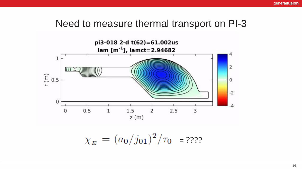
Sufficient thermal confinement time, at least several times longer than compression time *
Need to carefully consider thermal transport during compression
Analytic consideration is usually limited to the ideal adiabatic case, for spherical compression we have:
where CR(t) = R0/R(t) is the radial compression factor. Typically, to include thermal losses a full numerical approach is taken. However much insight can be gained by looking at thermal diffusion within a periodic cylinder approximation of a torus (r = minor radius), compressed in a spherical scaling. A solution for the temperature evolution exists of the form:
where = 2.4048 is the first root of Bessel function J0(x), = initial minor radius of plasma, and cE is the global thermal diffusivity, which is possibly a function of time. The time-dependent part T(t) further simplifies for a class of compression trajectories with constant cE of the form:

15
Sufficient thermal confinement time, at least several times longer than compression time *
The values of cE, e, and tacc are related through:
Thermal diffusivity cE is related to initial thermal confinement time t0 by:
Slightly simpler to work with thermal t0 and total Compression time Dtcomp. Isothermal case
tacc = t0
Moderate heatinge = 1.5t0 = 4 tacc
Significant heatinge = 1.8t0 = 10 tacc
-1
16
Need to measure thermal transport on PI-3
= ????
17
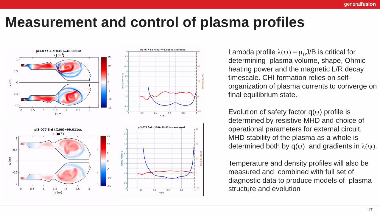
Lambda profile l(y) = m0J/B is critical for
determining plasma volume, shape, Ohmic
heating power and the magnetic L/R decay
timescale. CHI formation relies on self-
organization of plasma currents to converge on
final equilibrium state.
Evolution of safety factor q(y) profile is
determined by resistive MHD and choice of
operational parameters for external circuit.
MHD stability of the plasma as a whole is
determined both by q(y) and gradients in l(y).
Temperature and density profiles will also be
measured and combined with full set of
diagnostic data to produce models of plasma structure and evolution
Measurement and control of plasma profiles

18
Analysis and forward modeling of fluctuation
data from:
• magnetic probes,
• X-ray and optical radiometry,
• interferometry
can provided constraints on plasma profiles
and dynamic processes.
Interaction with the wall and the physics within the edge region is critical to work in MTF.
Fluctuations and edge physics

19
Multi-point TS
FIR polarimeter array
Optical
access
Inner surface
B-dot array
Equatorial diagnostic plane
• Multi-point Thomson scattering.
• Ion Doppler spectroscopy.
• Soft X-ray radiometry.
• Extend the use of soft X-ray diagnostics to
better constrain the position of the inversion
radius during sawtooth oscillations.
• Soft X-ray and visible plasma imaging.
• Surface magnetic probe array data.
• Multi-chord FIR polarimeter array.
• Impurity composition will be assessed
through time-resolved visible survey
spectroscopy, VUV spectroscopy.
• High energy scintillators detect hard X-rays
produced by run-away electrons, and neutrons produced during deuterium shots.
Diagnostic Plan
22
Twitter@generalfusion
Instagram@generalfusion
LinkedIngeneral-fusion


