
Powering Issues - Wirelesswireless.ictp.it/school_2007/lectures/Ermanno/powering_issues2007.pdf ·...
76
Pietrosemoli Pietrosemoli 1 Pietrosemoli Powering -1 Powering Issues Abdus Salam ICTP, February 2007 ICTP-ITU School on Wireless Networking for Scientific Applications in Developing Countries Ermanno Pietrosemoli Latin American Networking School (Fundación EsLaRed) – ULA Mérida Venezuela www.eslared.org.ve
Transcript of Powering Issues - Wirelesswireless.ictp.it/school_2007/lectures/Ermanno/powering_issues2007.pdf ·...

Pietrosemoli Pietrosemoli 1Pietrosemoli Powering - 1
Powering Issues
Abdus Salam ICTP, February 2007ICTP-ITU School on
Wireless Networking for Scientific Applications
in Developing CountriesErmanno PietrosemoliLatin American Networking School(Fundación EsLaRed) – ULAMérida Venezuela www.eslared.org.ve
Pietrosemoli Pietrosemoli 2Pietrosemoli Powering - 2
Powering Issues
Agenda:Grounding and BondingPower faultsPower over EthernetSolar and Wind Power
Pietrosemoli Pietrosemoli 3Pietrosemoli Powering - 3
Grounding & BondingReasons for Grounding• Personnel safety• Protection from high voltages
– Lightning– Power faults
• Dissipate electrostatic charges• Provide a zero volt reference• Protection of electronic equipment• Reduction of noise and interference
Pietrosemoli Pietrosemoli 4Pietrosemoli Powering - 4
• Even though damage is not usually visible with electrostatic discharge, it is the leading cause of electronic equipment failure.
• Humidity and temperature can help control electrostatic energy, but protection must also be deployed to prevent damage.
Pietrosemoli Pietrosemoli 5Pietrosemoli Powering - 5
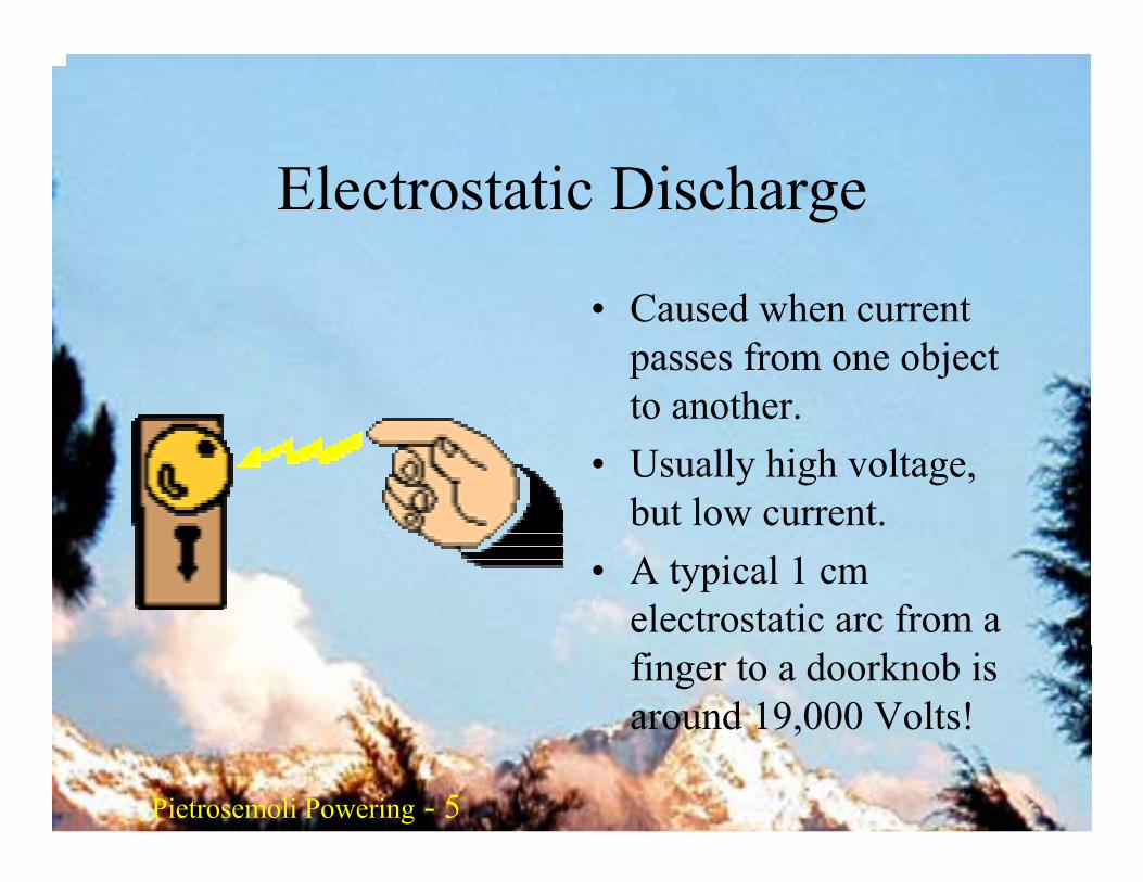
Electrostatic Discharge
• Caused when current passes from one object to another.
• Usually high voltage, but low current.
• A typical 1 cm electrostatic arc from a finger to a doorknob is around 19,000 Volts!
Pietrosemoli Pietrosemoli 6Pietrosemoli Powering - 6
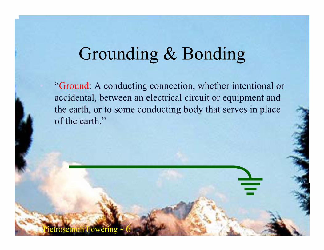
Grounding & Bonding• “Ground: A conducting connection, whether intentional or
accidental, between an electrical circuit or equipment and the earth, or to some conducting body that serves in place of the earth.”
Pietrosemoli Pietrosemoli 7Pietrosemoli Powering - 7
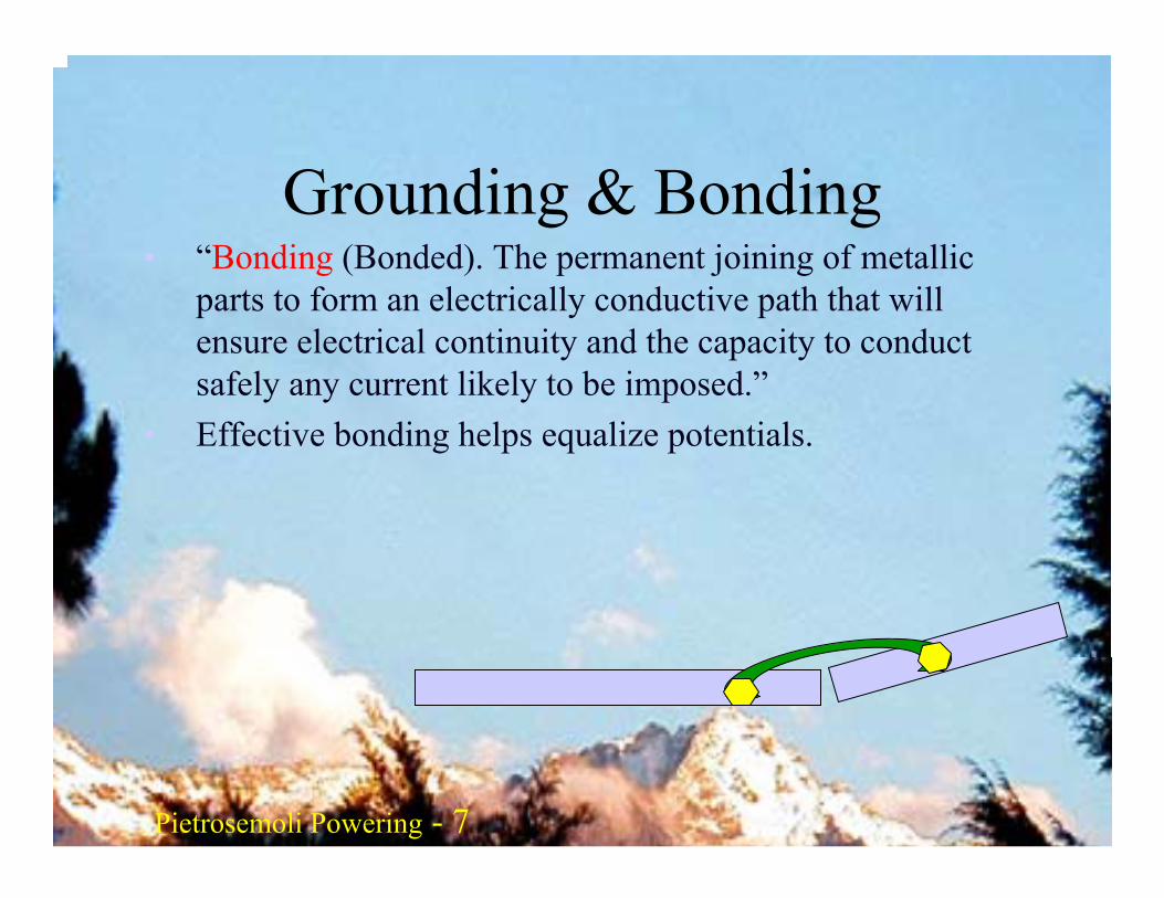
Grounding & Bonding• “Bonding (Bonded). The permanent joining of metallic
parts to form an electrically conductive path that will ensure electrical continuity and the capacity to conduct safely any current likely to be imposed.”
• Effective bonding helps equalize potentials.
Pietrosemoli Pietrosemoli 8Pietrosemoli Powering - 8
Grounding & Bonding• Grounding in a cabling installation refers to
connecting non-current carrying metal parts of conduits, raceways, conductors and electrical equipment to a building’s system ground.
Pietrosemoli Powering - 9
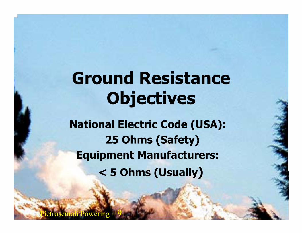
Ground Resistance Objectives
National Electric Code (USA):25 Ohms (Safety)
Equipment Manufacturers:
< 5 Ohms (Usually)
Pietrosemoli Pietrosemoli 10Pietrosemoli Powering - 10
Conductor Surface Area
The most effective material for a ground system is copper strap. Copper as a metal is a good electrical conductor, only moderately attacked by ground and air borne acids, and should have a life-span measured in years.
Since lightning has a large portion of its energy in the RF range, it will behave like an RF signal. That means the energy will only be conducted on the skin of the conductor (skin effect). Such currents following a round-member conductor will not make extensive use of its large cross sectional area. With a 1-1/2 inch (38 mm) or larger flat strap of at least 26 gauge (0.41 mm), both surfaces will conduct the surge.
Pietrosemoli Pietrosemoli 11Pietrosemoli Powering - 11
Soil Doping
The earth is a conductor because of the number of ionic salts present in the soil. Conductivity can be improved by adding more ions to the soil.
Soil doping can be done by either adding water or a saline solution to the soil around the grounding system. If the soil already has a sufficient amount of naturally occurring salts, adding water will free the ions and improve conductivity.
If few natural ions are available, salts, such as Epsom salts, can be added to the soil to increase the conductivity.
Depending on the amount of rainfall, doping the ground system radials with 10 kg of salt per per rod may last approximately two years.
Pietrosemoli Pietrosemoli 12Pietrosemoli Powering - 12
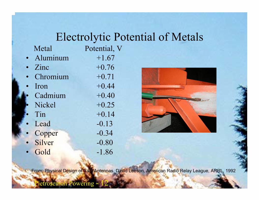
Electrolytic Potential of MetalsMetal Potential, V
• Aluminum +1.67• Zinc +0.76• Chromium +0.71• Iron +0.44• Cadmium +0.40• Nickel +0.25• Tin +0.14• Lead -0.13• Copper -0.34• Silver -0.80• Gold -1.86
From: Physical Design of Yagi Antennas. David Leeson, American Radio Relay League, ARRL, 1992
Pietrosemoli Pietrosemoli 13Pietrosemoli Powering - 13
Grounding & BondingGrounding System ComponentsThe two areas of grounding that pertain to telecommunications equipment are the:• Grounding electrode system (earthing system)• Equipment grounding system (safety ground)
Pietrosemoli Pietrosemoli 14Pietrosemoli Powering - 14
Metal Corrosion• To minimize electrolytic corrosion when two
differente metals are in moist contact theirelectrolytical potential should be as close as possible.
• Avoid attaching brass (which contains copper) toaluminum because their electrolytic potentialdifference is 2.01 V
• In the presence of oxygen, the zinc of galvanizedsteel sacrices itself before the steel corrodes, sincezinc is more negative than iron
Pietrosemoli Pietrosemoli 15Pietrosemoli Powering - 15
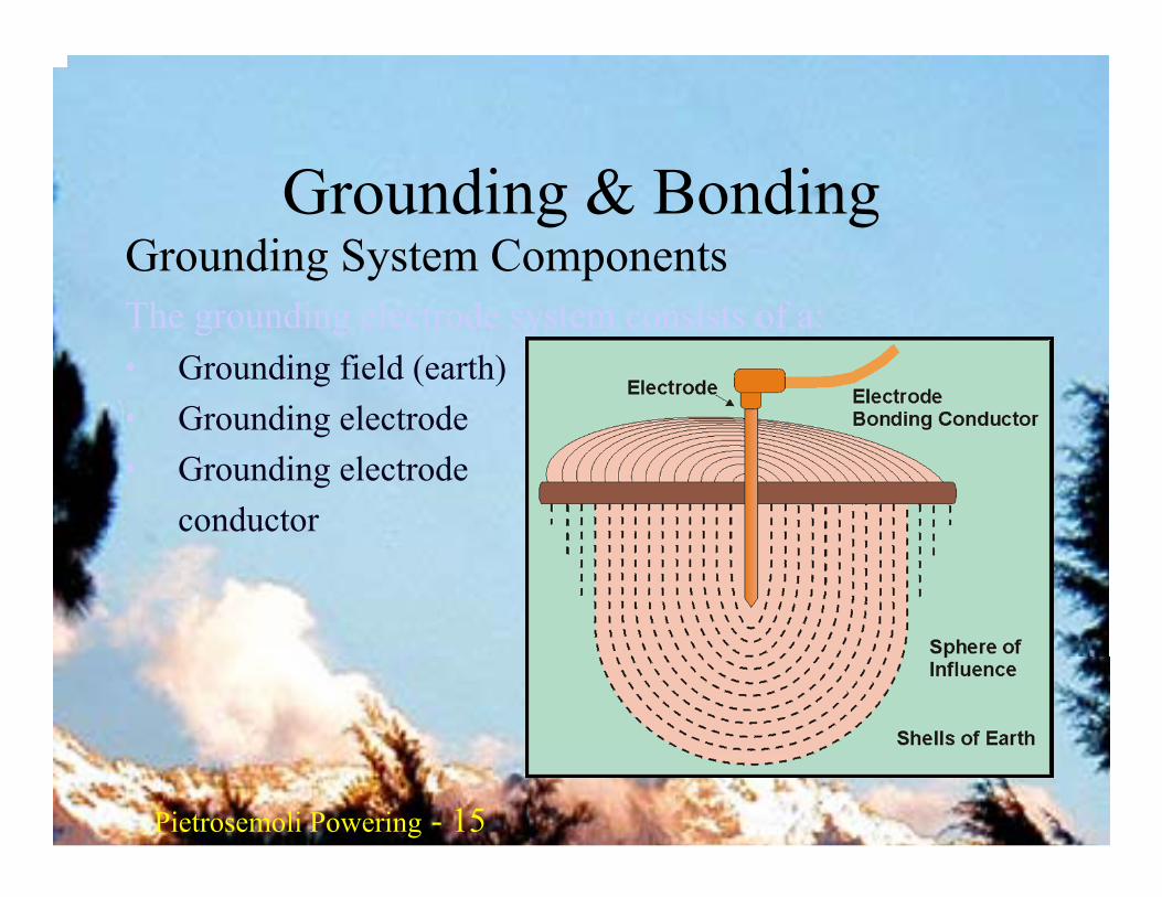
Grounding & BondingGrounding System ComponentsThe grounding electrode system consists of a:• Grounding field (earth)• Grounding electrode• Grounding electrode
conductor
Pietrosemoli Pietrosemoli 16Pietrosemoli Powering - 16
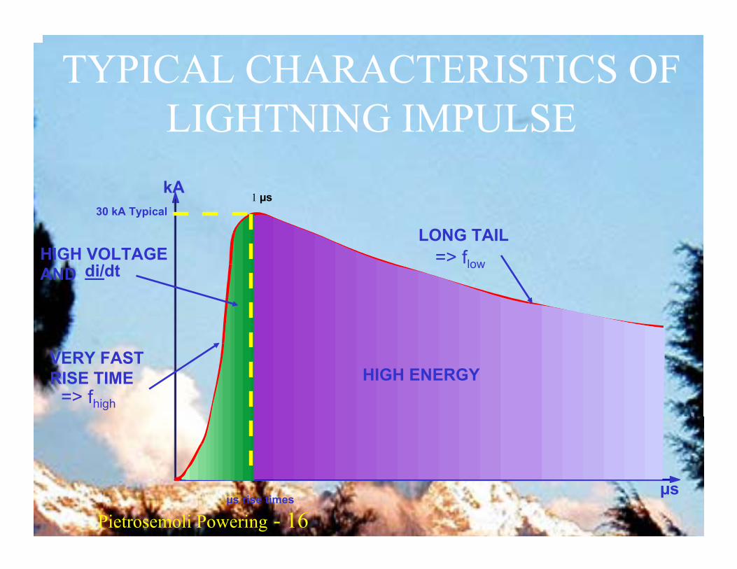
TYPICAL CHARACTERISTICS OF LIGHTNING IMPULSE
30 kA Typical
VERY FASTRISE TIME
=> fhigh
HIGH VOLTAGEAND di/dt
LONG TAIL=> flow
µs rise times
HIGH ENERGY
µs
kA1 µs
Pietrosemoli Pietrosemoli 17Pietrosemoli Powering - 17
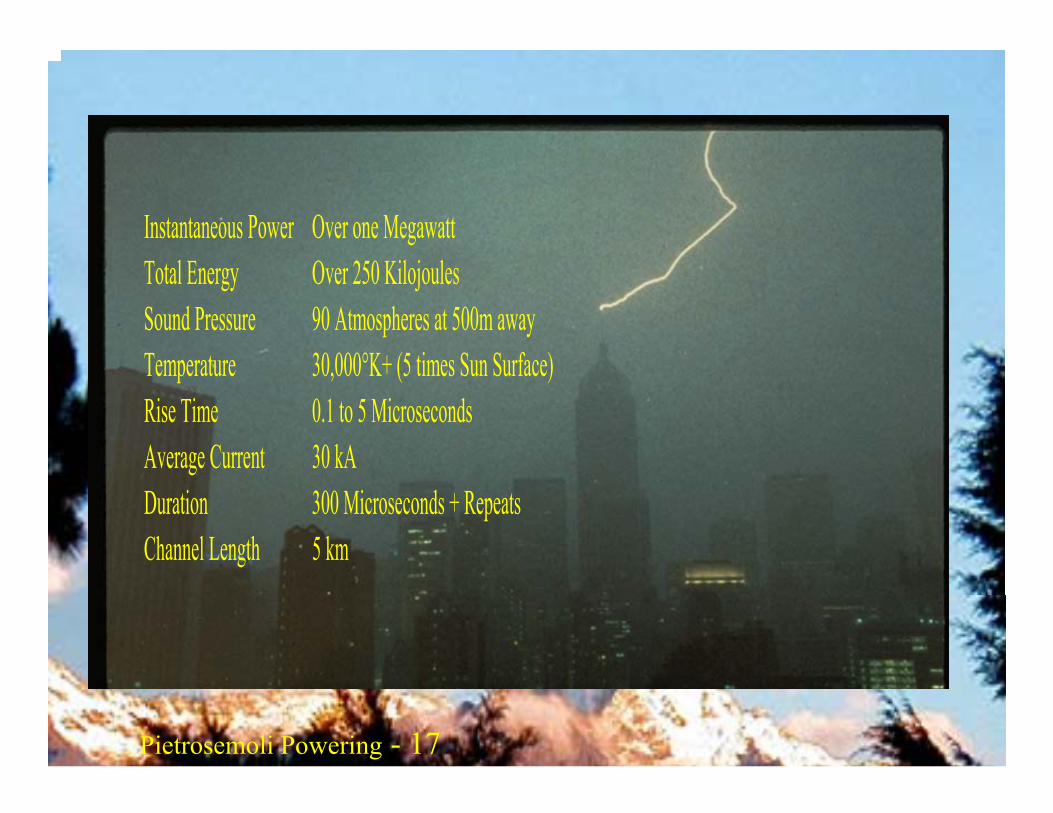
Instantaneous Power Over one Megawatt Total Energy Over 250 Kilojoules Sound Pressure 90 Atmospheres at 500m away Temperature 30,000°K+ (5 times Sun Surface)Rise Time 0.1 to 5 Microseconds Average Current 30 kA Duration 300 Microseconds + Repeats Channel Length 5 km
Pietrosemoli Pietrosemoli 18Pietrosemoli Powering - 18
Grounding Electrode System
Grounding Electrode:• Metallic conductor (e.g., rod 17 mm in diameter),
pipe (19 mm diameter) at least 2.4 m long, plate, ring, or other metallic object) in contact with the earth used to establish a low resistance current path to earth
Grounding Electrode System:• Network of electrically connected ground electrodes
used to achieve an improved low resistance to earth
Pietrosemoli Pietrosemoli 19Pietrosemoli Powering - 19
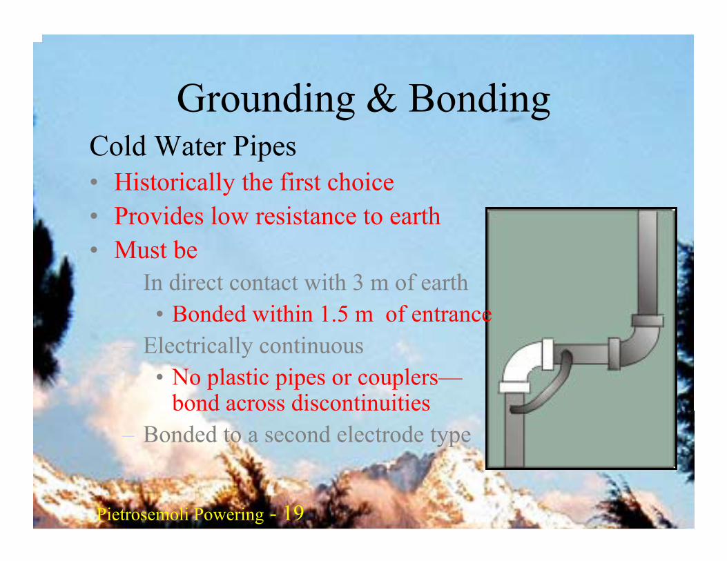
Grounding & BondingCold Water Pipes• Historically the first choice• Provides low resistance to earth• Must be:
– In direct contact with 3 m of earth• Bonded within 1.5 m of entrance
– Electrically continuous• No plastic pipes or couplers—
bond across discontinuities– Bonded to a second electrode type

Pietrosemoli Pietrosemoli 20Pietrosemoli Powering - 20
Grounding & BondingCold Water PipesAdvantages:• Most homes have water• Easily accessible• Usually less than 3 Ω resistance
to earth
Pietrosemoli Pietrosemoli 21Pietrosemoli Powering - 21
Grounding & BondingCold Water PipesDisadvantages:• Future repairs may be plastic• Many cities use PVC• Bonding causes electrolysis of the installed metallic
pipes, causing reduced expected life span– Many cities are installing isolation joints made of
PVC to separate their systems
Pietrosemoli Pietrosemoli 22Pietrosemoli Powering - 22
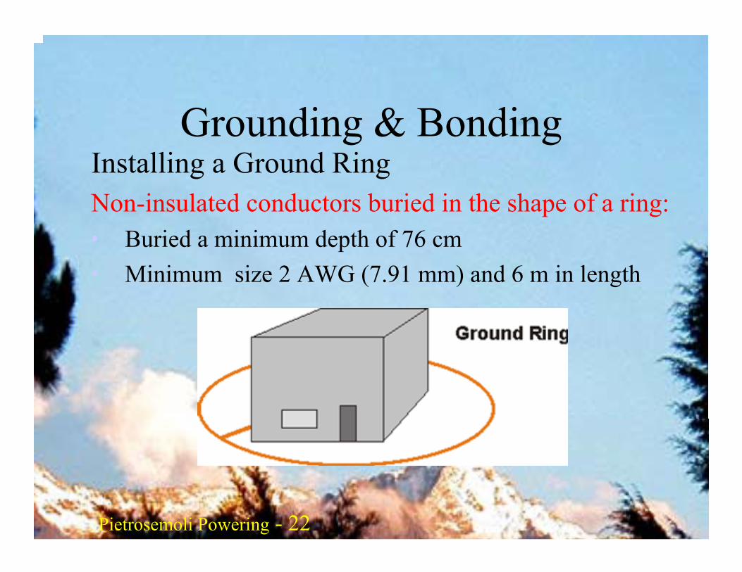
Grounding & BondingInstalling a Ground RingNon-insulated conductors buried in the shape of a ring:• Buried a minimum depth of 76 cm • Minimum size 2 AWG (7.91 mm) and 6 m in length
Pietrosemoli Pietrosemoli 23Pietrosemoli Powering - 23
Ground Radials
Radials are the most cost effective grounding technique considering system impedance, material cost, and installation labor. If one radial gives “X” resistance, then two will deliver an equivalent “parallel rule” plus 10%.
Radials do have a limit on their effective length. If the surge energy has not been launched into the soil within
the first 22 m, the inductance of the radial will prevent any further effective prorogation. Therefore, as a general rule of thumb, all radials should be at least 15 m long and no longer than 23 m.
Pietrosemoli Pietrosemoli 24Pietrosemoli Powering - 24
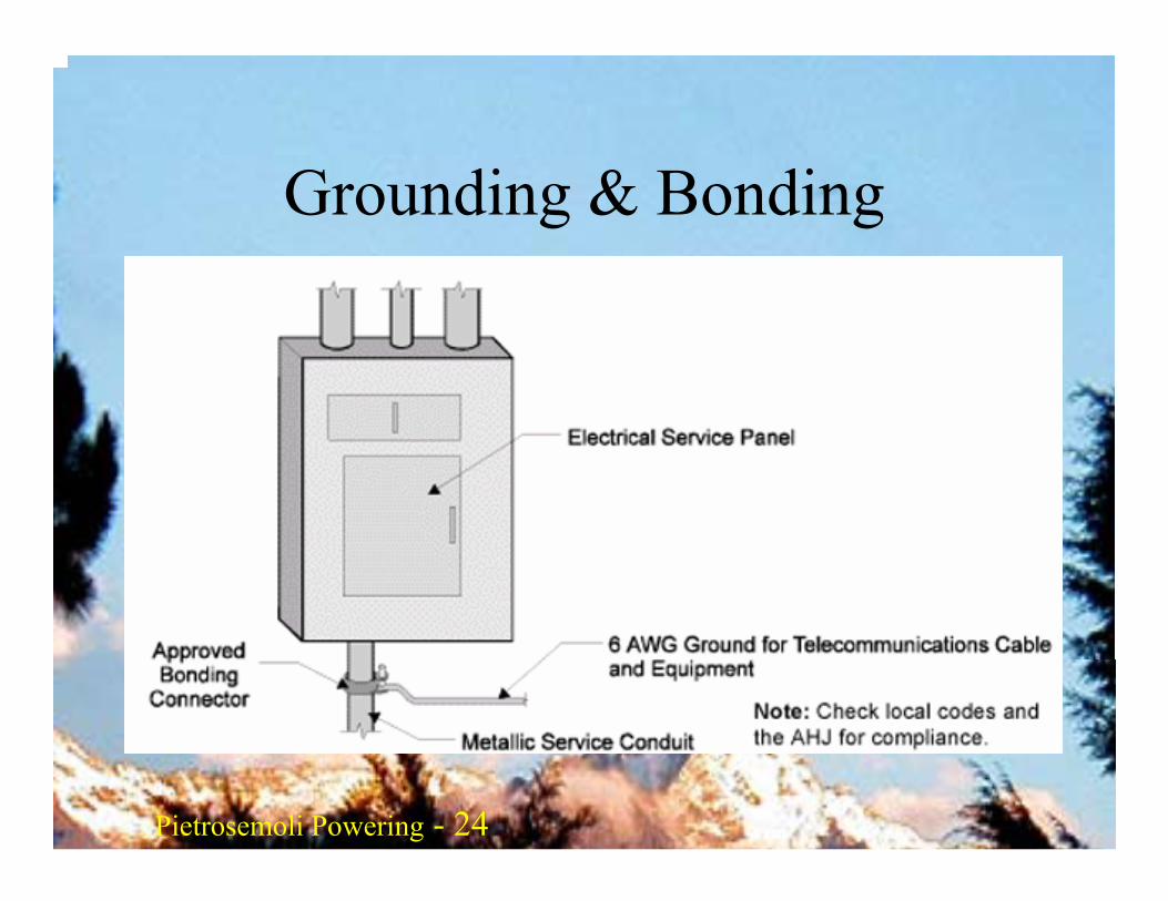
Grounding & Bonding
Using an Electrical Service Ground
Pietrosemoli Pietrosemoli 25Pietrosemoli Powering - 25
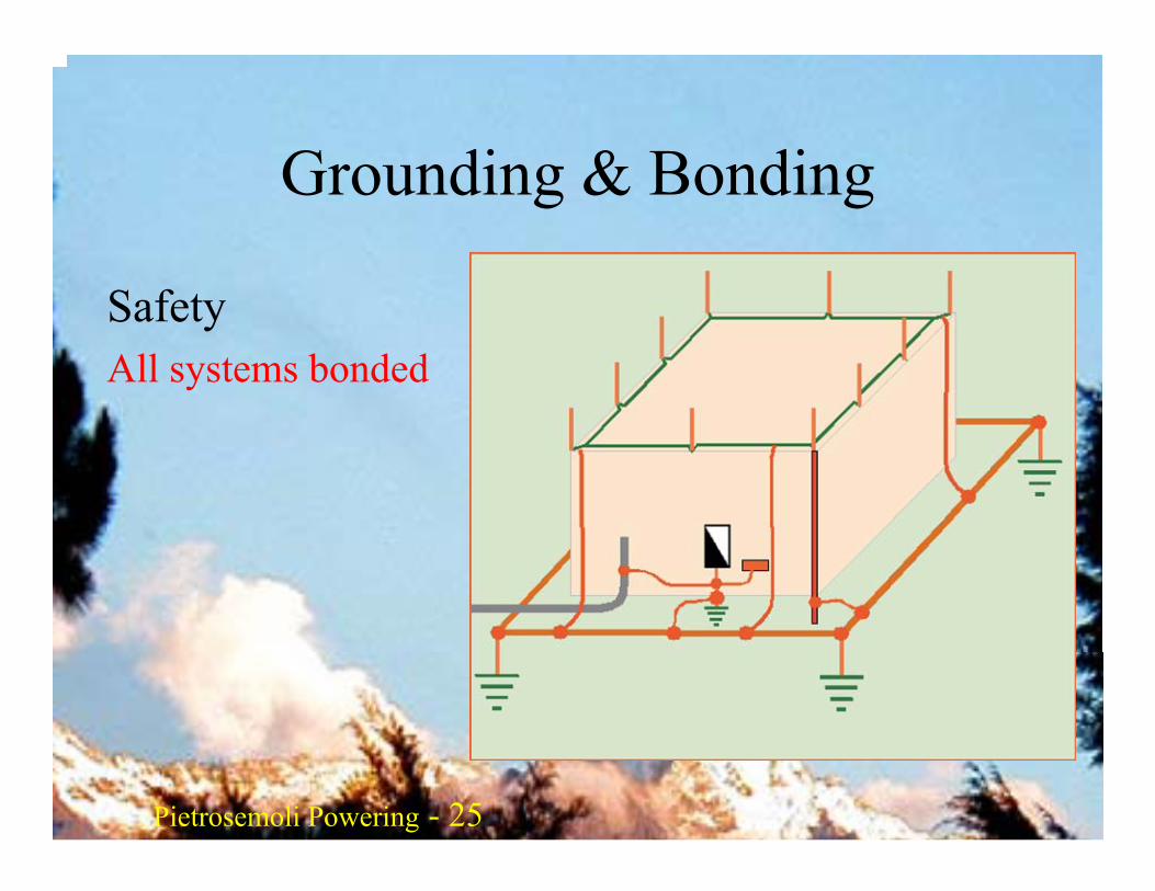
Grounding & Bonding
SafetyAll systems bonded
Pietrosemoli Pietrosemoli 26Pietrosemoli Powering - 26
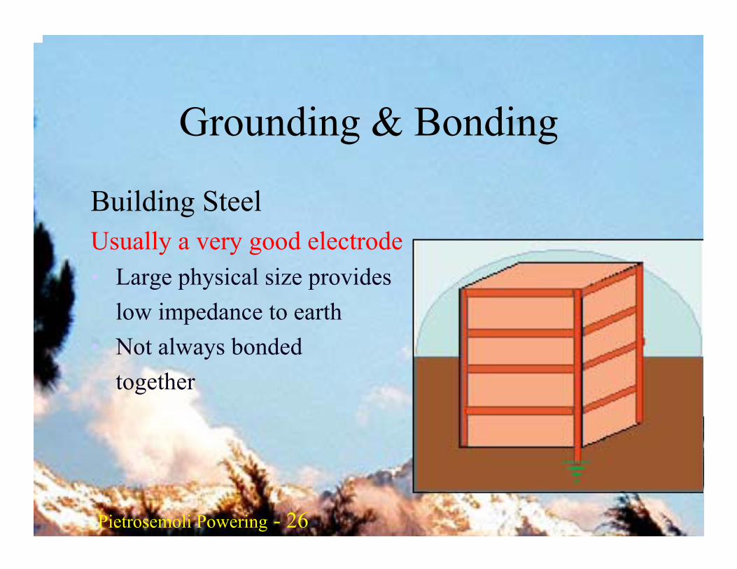
Grounding & Bonding
Building SteelUsually a very good electrode• Large physical size provides
low impedance to earth• Not always bonded
together
Pietrosemoli Pietrosemoli 27Pietrosemoli Powering - 27
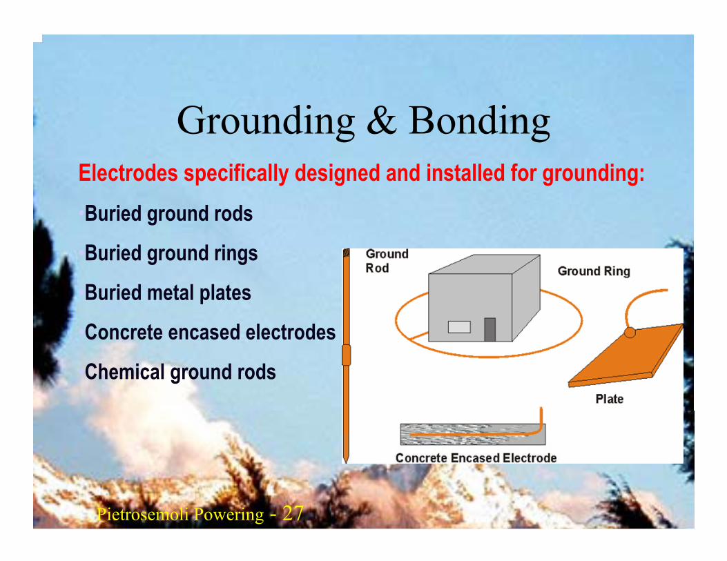
Grounding & BondingElectrodes specifically designed and installed for grounding:•Buried ground rods
•Buried ground rings
•Buried metal plates
•Concrete encased electrodes
•Chemical ground rods
Pietrosemoli Pietrosemoli 28Pietrosemoli Powering - 28
Grounding & Bonding• Generally speaking, “earth resistance” is the
resistance of soil to the passage of electrical current
• The earth is a relatively poor conductor of electricity compared to normal conductors like copper wire. But, if the path for current is large enough, the resistance can be quite low and earth can be a good conductor
Pietrosemoli Pietrosemoli 29Pietrosemoli Powering - 29
Grounding & BondingSeveral factors can affect the resistance:• Moisture content of the soil• Quantity of electrolytes • Type of electrolytes• Adjacent conductors• Temperature• Electrode depth• Electrode diameter• Electrode(s) spacing distance

Pietrosemoli Pietrosemoli 30Pietrosemoli Powering - 30
Grounding & BondingResistivities of Different Soils
Pietrosemoli Pietrosemoli 31Pietrosemoli Powering - 31
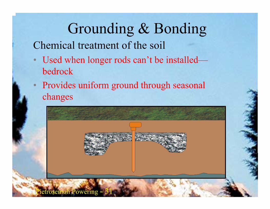
Grounding & BondingChemical treatment of the soil• Used when longer rods can’t be installed—
bedrock• Provides uniform ground through seasonal
changes
Pietrosemoli Pietrosemoli 32Pietrosemoli Powering - 32
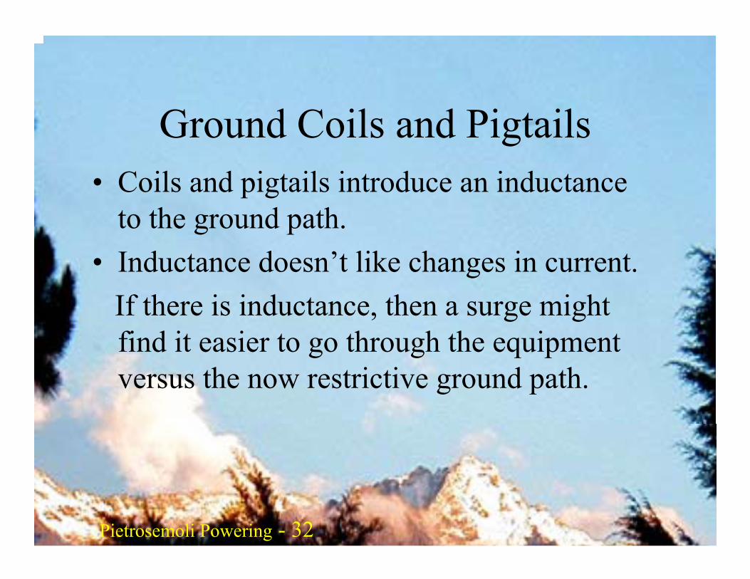
Ground Coils and Pigtails• Coils and pigtails introduce an inductance
to the ground path.• Inductance doesn’t like changes in current.
If there is inductance, then a surge might find it easier to go through the equipment versus the now restrictive ground path.
Pietrosemoli Pietrosemoli 33Pietrosemoli Powering - 33
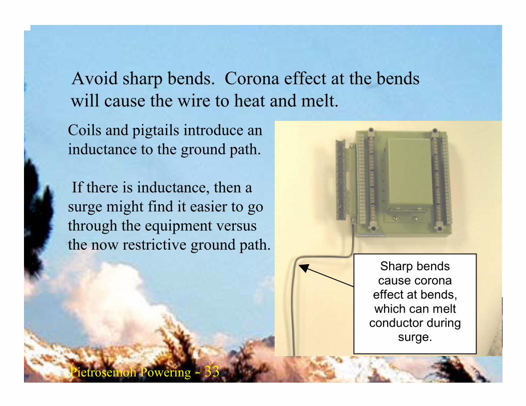
Avoid sharp bends. Corona effect at the bends will cause the wire to heat and melt.
Sharp bends cause corona
effect at bends, which can melt
conductor during surge.
Coils and pigtails introduce an inductance to the ground path.
If there is inductance, then a surge might find it easier to go through the equipment versus the now restrictive ground path.
Pietrosemoli Pietrosemoli 34Pietrosemoli Powering - 34
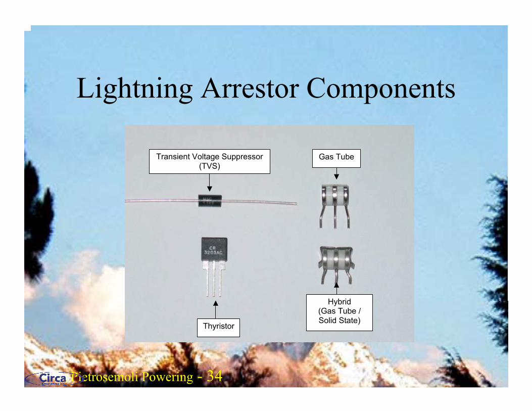
Lightning Arrestor Components
Transient Voltage Suppressor(TVS)
Gas Tube
Thyristor
Hybrid (Gas Tube / Solid State)
Pietrosemoli Pietrosemoli 35Pietrosemoli Powering - 35
Ground Antenna Mast
It is recommended that the antenna mast be grounded to either the building rooftop lightning ground system or to a separate earth ground system. The mast should be connected to the ground by a low resistance cable, size AWG #10 (3.43mm diameter) copper or larger. Use suitable ground clamps to attach the cable to the mast and the ground system. Make sure the cable is making a good electrical connection, remove all paint and corrosion from the area the clamp attaches to. Use dielectric grease on the clamp connection to prevent any electrolysis activity due to dissimilar metals.
Pietrosemoli Pietrosemoli 36Pietrosemoli Powering - 36
Dissimilar Metals
Copper should never touch galvanized material directly without proper joint protection. Water shedding
from the copper contains ions that will wash away the galvanized (zinc) tower covering. Stainless steel
can be used as a buffer material. However, be aware that stainless steel is not a very good conductor. If
it is used as a buffer between copper and galvanized metals, the surface area of the contact should be
large and the stainless steel should be thin. Joint compound should also be used to cover the connection
so water can not bridge between the dissimilar metals.
Pietrosemoli Pietrosemoli 37Pietrosemoli Powering - 37
Electrical Power Faults
Types of Electrical System Faults• Phase-to-phase faults• Phase-to-neutral faults• Phase-to-ground
– Greater than 90% of electrical system faults will be phase-to-ground faults
– A phase-to-phase or phase-to-neutral fault will almost always trip the overcurrent device
Pietrosemoli Pietrosemoli 38Pietrosemoli Powering - 38
Electrical Power Faults
A phase-to-ground fault will not trip the overcurrentdevice if the impedance of the equipment grounding system is too high.• The following factors govern equipment grounding
conductor impedance:• Tightness of connections• Length• Proximity to circuit conductors during fault conditions• Number of bends and bend radius

Pietrosemoli Pietrosemoli 39Pietrosemoli Powering - 39
PoEWhy Power Ethernet?• Saves money and installation time• More flexibility in the placing of devices• Quite useful for outdoors install, allows for
a long distance between the AP and the computer
• Does not require an electrician to install
Pietrosemoli Pietrosemoli 40Pietrosemoli Powering - 40
PoE Issues• Standard or not• End Span• Mid Span• Cat5e or Cat6 less than 25 ohm loop• Pin assignment A or B• Measured resistance for 10 m, 0.8 ohm• Outdoor rated UTP Cable• Signature
Pietrosemoli Pietrosemoli 41Pietrosemoli Powering - 41
IEEE Std 802.3af-2003
• Powering Ethernet Devices through data cables
• Standard Titled: Data Terminal Equipment (DTE) Power via Media Dependent Interface (MDI)
• Approved June 2003
Pietrosemoli Pietrosemoli 42Pietrosemoli Powering - 42
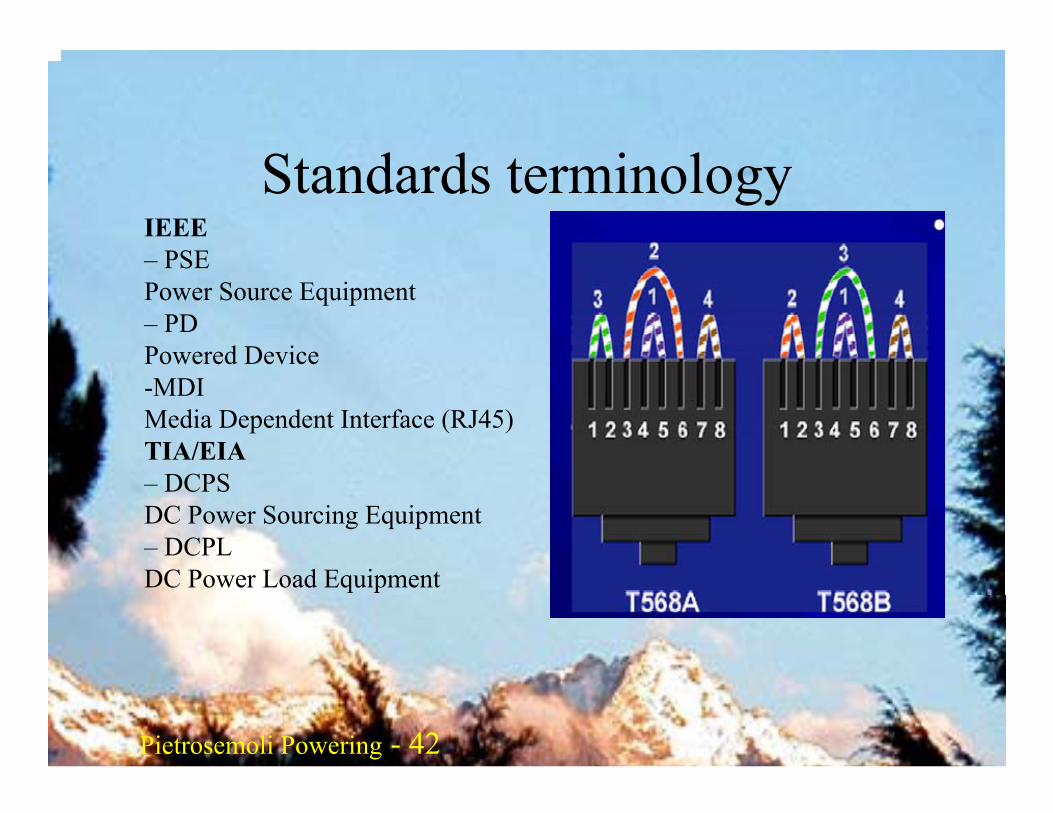
Standards terminologyIEEE– PSEPower Source Equipment– PDPowered Device-MDIMedia Dependent Interface (RJ45)TIA/EIA– DCPSDC Power Sourcing Equipment– DCPLDC Power Load Equipment
Pietrosemoli Pietrosemoli 43Pietrosemoli Powering - 43
End span or mid span
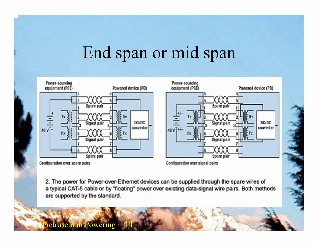
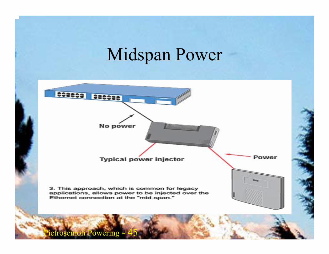
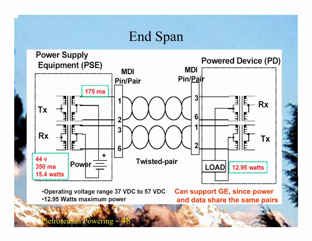
• PoE (802.3af) runs at 48VDC, with a max current of 350mA, capable of feeding a maximum load of 12.95W accounting for the cable losses
• End span 802.3af provides power on either the data pairs (1,2;3,6) or spare pairs (4,5;7,8), while "mid span" 802.3af provides power on the spare pairs (4,5;7,8).
Pietrosemoli Pietrosemoli 44Pietrosemoli Powering - 44
End span or mid span
Pietrosemoli Pietrosemoli 45Pietrosemoli Powering - 45
Midspan Power
Pietrosemoli Pietrosemoli 46Pietrosemoli Powering - 46
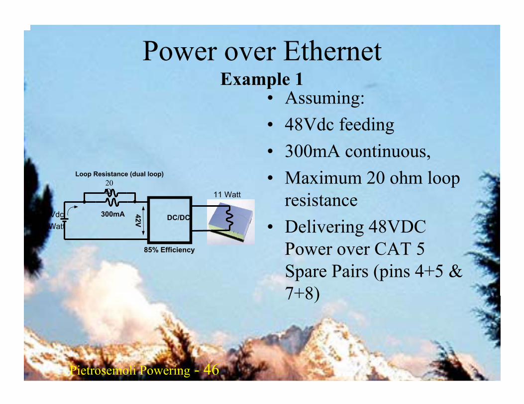
DC/DC
85% Efficiency
20Ω
Loop Resistance (dual loop)
300mA48Vdc16 Watt
42V
11 Watt
Power over EthernetExample 1
• Assuming:• 48Vdc feeding• 300mA continuous, • Maximum 20 ohm loop
resistance• Delivering 48VDC
Power over CAT 5 Spare Pairs (pins 4+5 & 7+8)
Pietrosemoli Pietrosemoli 47Pietrosemoli Powering - 47
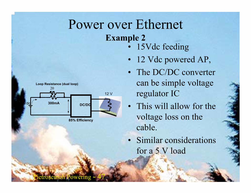
DC/DC
85% Efficiency
20Ω
Loop Resistance (dual loop)
300mA15Vdc
12 V
Power over EthernetExample 2
• 15Vdc feeding• 12 Vdc powered AP, • The DC/DC converter
can be simple voltage regulator IC
• This will allow for the voltage loss on the cable.
• Similar considerations for a 5 V load
Pietrosemoli Pietrosemoli 48Pietrosemoli Powering - 48
End Span
Can support GE, since powerand data share the same pairs
Pietrosemoli Pietrosemoli 49Pietrosemoli Powering - 49
•PSE applies test voltages to determine the load characteristic of the PD.•The load characteristics of the PD are called the PD detection signature.•The PSE reads the PD detection signature to determine whether to supply power and how much power to supply.•The detection signature enables the PSE to provide the right level of power, providing a form of power regulation.Implemented only in high end switches
Powered Device detection signature
DIY• Detailed instructions on how to build your own PoE
device can be found at http://www.nycwireless.net/poe/ andhttp://socalfreenet.org/poe
• A java applet calculator for voltage drop can be found at http://www.gweep.net/~sfoskett/tech/poecalc.htmlBeware that this calculator assumes that the voltage drop occurs only in one of the two wires that reach the PD, which is true only if both ends of the cable are attached to the same ground potential

Pietrosemoli Pietrosemoli 51Pietrosemoli Powering - 51
Most autonomous solar systems work at 12 or 24 volts. Preferably, a wireless device that runs on DC voltage should be used, operating at the 12 Volts thatmost lead acid batteries provide. A router oraccess point that accepts 8-20 Volts DC is perfect.Most cheap access points have a switched mode voltage regulator inside and will work through such a voltage range without modification or becoming hot (even if the device was shipped with a 5 or 12 Volt power supply).
Remote site powering
WARNING: Operating your access point with a power supply other than theone provided by your manufacturer will certainly void any warranty, and maycause damage to your equipment. While the following technique will typicallywork as described, remember that should you attempt it, you do so at yourown risk.
Pietrosemoli Pietrosemoli 52Pietrosemoli Powering - 52
BatteriesLead acid batteries contain sulfuric acid that can cause severe burns. They release hydrogen when they are charged or have a short between terminals even when they are the sealed acid type. Proper venting is necessary to prevent explosions, especially if the batteries are of the flooded cell acid type.It is a good idea to protect your eyes with safety glasses when handling these batteries. Lead is toxic - make sure you dispose of worn out batteries properly.
Pietrosemoli Pietrosemoli 53Pietrosemoli Powering - 53
Calculating and measuring power consumption
The easiest way to measure your device is a laboratory power supply that features a voltage and ampere meter. Thenominal voltage provided by a lead acid battery typically varies between 11Volts (empty) and about 14.5 Volt (charging, voltage at charging limit). You can tune the voltage at the laboratory power supply and see how much current the device draws at different voltages. If a laboratory power supply is not available, measurement can be performed by using the supply shipped with the device. Interrupt one cable that goes to the DC input of your device and insert an ampere-meter (or ammeter).
Pietrosemoli Pietrosemoli 54Pietrosemoli Powering - 54
Calculating and measuring power consumption
The amount of power consumed can be calculated with this formula:P = U * IP being Power in Watts, U being voltage in Volts, I being current in Ampere.For example:6 Watts = 12 Volts * 0.5 AmpereThe result is the rating of the device. If the device of the example is operating for an hour it will simply consume 6 Watt-hours (Wh), respectively 0.5 Ampere-hours (Ah). Thus the device will draw 144 Wh or 12 Ah a day.
Pietrosemoli Pietrosemoli 55Pietrosemoli Powering - 55
Discharging characteristics - Rule of thumb
A 12 volt lead-acid battery that delivers energy to a consumer provides a voltage depending on it's state of charge. When the battery is 100% charged it has an output voltage of 12.8 volts which is quickly dropping to 12.6 volts under load. Beneath 11.6 volt the output voltage is dropping down quickly over time.Since the battery provides approximately 95% of it's power within this linear voltage drop, the charging state could be estimated by measuring the voltage under load. The assumption is that the battery is 100% full at 12.6 V andhas 0% charge at 11.6 Volts. So, when measuring a battery that is currently discharged, the status can be estimated with a digital multimeter.
Pietrosemoli Pietrosemoli 56Pietrosemoli Powering - 56
Discharging characteristics - Rule of thumb
Lead acid batteries degrade quickly when charging cycles go down to 0 charge. A battery from a truck will lose 50% of it's design capacity within 50 -150 cycles if it is fully charged and discharged during each cycle.Never discharge a 12 Volt lead acid battery beneath this value. It will forfeit a huge amount of storage capacity. In cycle use it is not advisable to discharge a simple truckbattery beneath 70%. Not going beneath 80% will significantly increase it's durability. Thus a 170 Ah truck battery has only a usable capacity of 34 to 51 Ah.
Pietrosemoli Pietrosemoli 57Pietrosemoli Powering - 57
Discharging characteristics - Rule of thumb
Truck or car batteries that carry the label maintenance-free should have neglectable low self-discharge current. However, maintenance-free batteries still need maintenance. The level of the electrolyte fluid must be checkedfrequently, especially in hot climate. If there is loss of electrolyte, distilled water has to be used to fill up the fluid. Neglecting this will ruin the battery.Charging your batteries too much will destroy them too! The charging current in a battery buffered system must be regulated. Excessive and unlimited charging will destroy the battery.
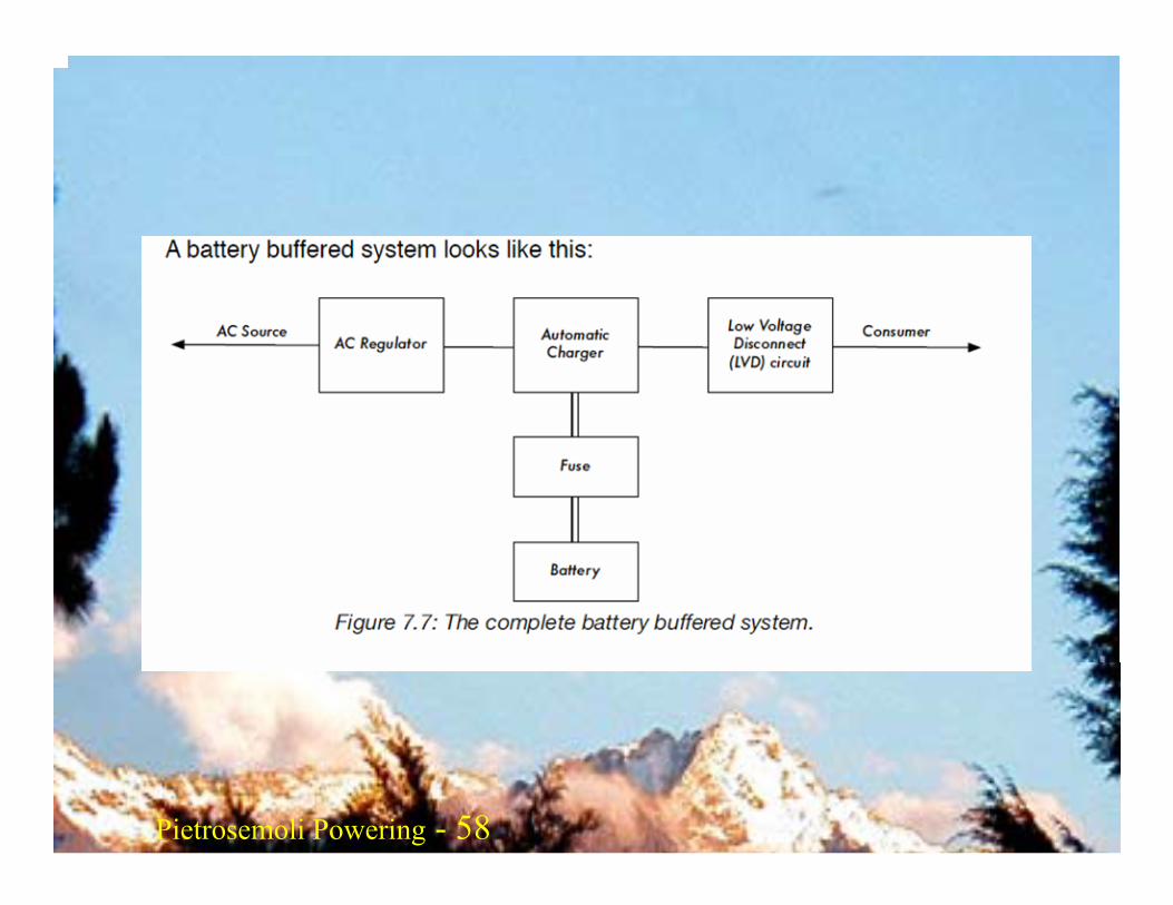
Pietrosemoli Pietrosemoli 58Pietrosemoli Powering - 58
Pietrosemoli Pietrosemoli 59Pietrosemoli Powering - 59
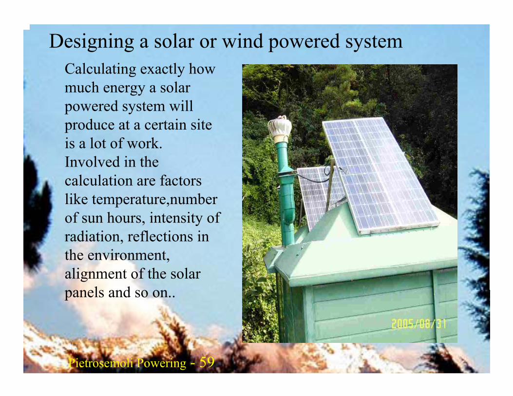
Designing a solar or wind powered systemCalculating exactly how much energy a solar powered system will produce at a certain site is a lot of work. Involved in the calculation are factors like temperature,numberof sun hours, intensity of radiation, reflections in the environment, alignment of the solar panels and so on..
Pietrosemoli Pietrosemoli 60Pietrosemoli Powering - 60
Solar power
It is important for a solar system that the solar panels are mounted with the best alignment and angle to the sun. The best angle may vary over the year and is dependent on the location of the site. The rule of thumb is towards South in thenorthern hemisphere and North in the southern hemisphere, with the same inclination as the latitude of the place.In summer it is better to decrease this value by 10 degreeswhile in winter it is advisable to increase by the same amount.It is a good idea to take into account that dust, leaves or birds may defile a solar panel. Shade must not wander over the solar panel during the day, because solar panels consist of a number of solar cells that are connected in a daisy chain.
Pietrosemoli Pietrosemoli 61Pietrosemoli Powering - 61
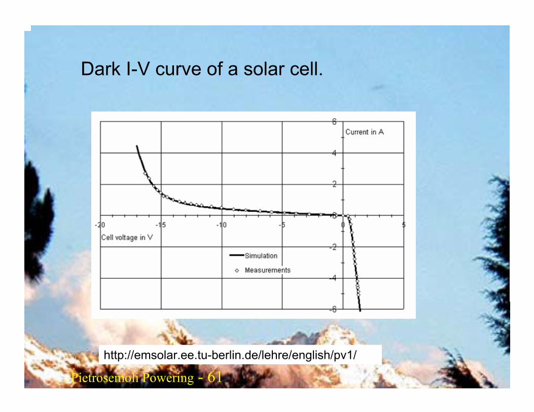
http://emsolar.ee.tu-berlin.de/lehre/english/pv1/
Dark I-V curve of a solar cell.
Pietrosemoli Pietrosemoli 62Pietrosemoli Powering - 62
http://emsolar.ee.tu-berlin.de/lehre/english/pv1/
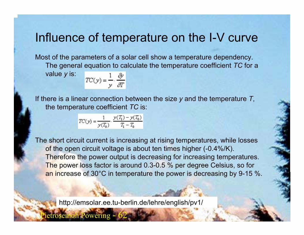
Influence of temperature on the I-V curveMost of the parameters of a solar cell show a temperature dependency.
The general equation to calculate the temperature coefficient TC for a value y is:
If there is a linear connection between the size y and the temperature T, the temperature coefficient TC is:
The short circuit current is increasing at rising temperatures, while losses of the open circuit voltage is about ten times higher (-0.4%/K). Therefore the power output is decreasing for increasing temperatures. The power loss factor is around 0.3-0.5 % per degree Celsius, so for an increase of 30°C in temperature the power is decreasing by 9-15 %.
Pietrosemoli Pietrosemoli 63Pietrosemoli Powering - 63
http://emsolar.ee.tu-berlin.de/lehre/english/pv1/
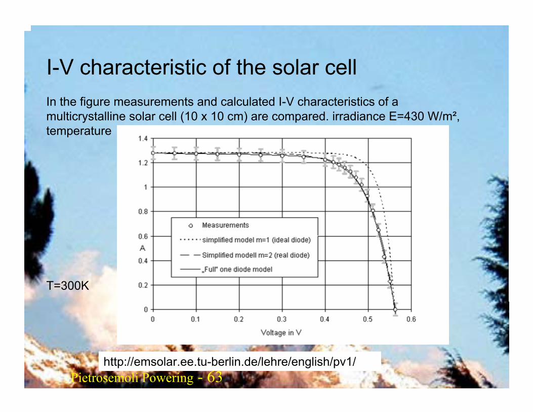
I-V characteristic of the solar cell In the figure measurements and calculated I-V characteristics of a multicrystalline solar cell (10 x 10 cm) are compared. irradiance E=430 W/m², temperature
T=300K
Pietrosemoli Pietrosemoli 64Pietrosemoli Powering - 64
http://emsolar.ee.tu-berlin.de/lehre/english/pv1/
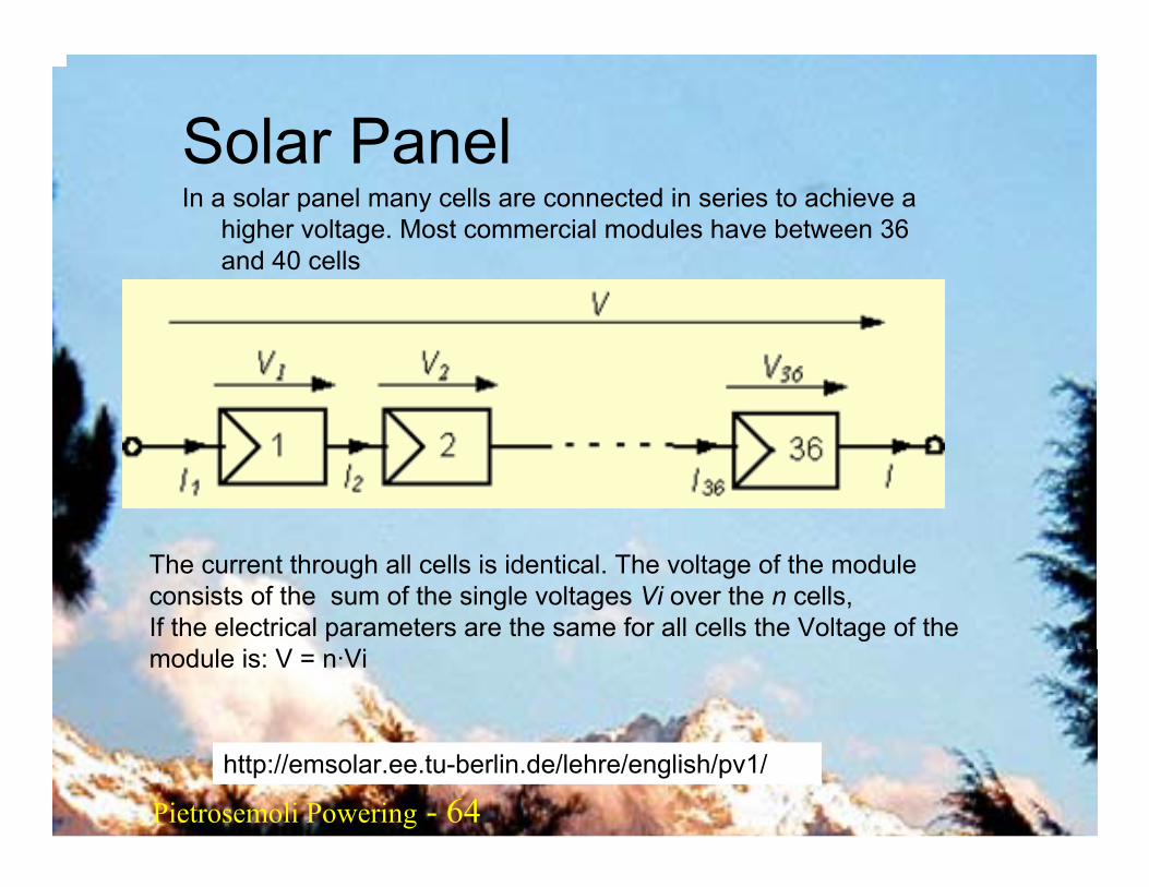
Solar PanelIn a solar panel many cells are connected in series to achieve a
higher voltage. Most commercial modules have between 36 and 40 cells
The current through all cells is identical. The voltage of the module consists of the sum of the single voltages Vi over the n cells,If the electrical parameters are the same for all cells the Voltage of the module is: V = n·Vi
Pietrosemoli Pietrosemoli 65Pietrosemoli Powering - 65
http://emsolar.ee.tu-berlin.de/lehre/english/pv1/
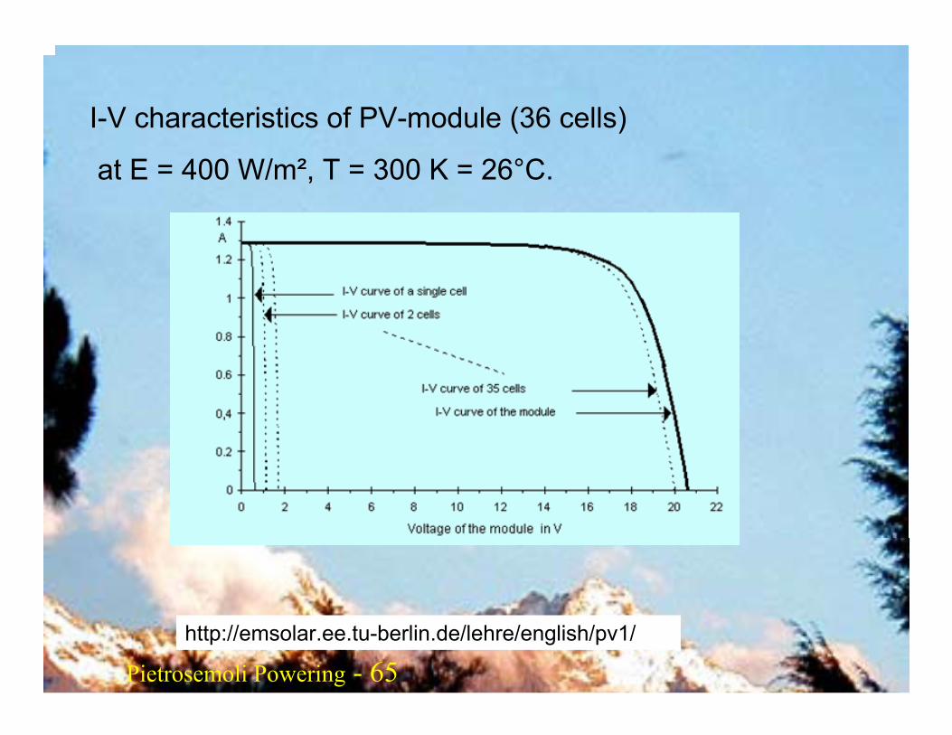
I-V characteristics of PV-module (36 cells)
at E = 400 W/m², T = 300 K = 26°C.
Pietrosemoli Pietrosemoli 66Pietrosemoli Powering - 66
http://emsolar.ee.tu-berlin.de/lehre/english/pv1/
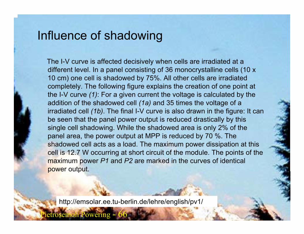
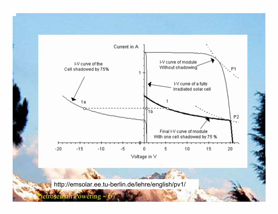
Influence of shadowing
The I-V curve is affected decisively when cells are irradiated at a different level. In a panel consisting of 36 monocrystalline cells (10 x 10 cm) one cell is shadowed by 75%. All other cells are irradiated completely. The following figure explains the creation of one point at the I-V curve (1): For a given current the voltage is calculated by the addition of the shadowed cell (1a) and 35 times the voltage of a irradiated cell (1b). The final I-V curve is also drawn in the figure: It can be seen that the panel power output is reduced drastically by this single cell shadowing. While the shadowed area is only 2% of thepanel area, the power output at MPP is reduced by 70 %. The shadowed cell acts as a load. The maximum power dissipation at this cell is 12.7 W occurring at short circuit of the module. The points of the maximum power P1 and P2 are marked in the curves of identical power output.
Pietrosemoli Pietrosemoli 67Pietrosemoli Powering - 67
http://emsolar.ee.tu-berlin.de/lehre/english/pv1/
Pietrosemoli Pietrosemoli 68Pietrosemoli Powering - 68
http://emsolar.ee.tu-berlin.de/lehre/english/pv1/
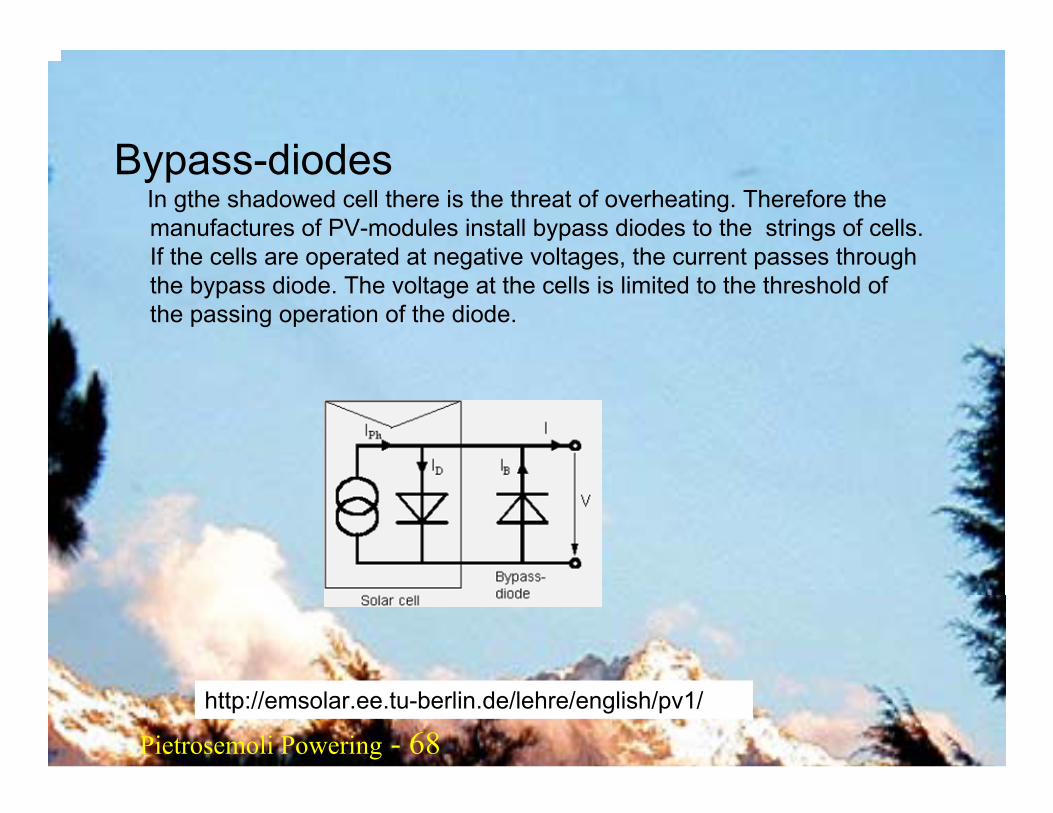
Bypass-diodes In gthe shadowed cell there is the threat of overheating. Therefore themanufactures of PV-modules install bypass diodes to the strings of cells. If the cells are operated at negative voltages, the current passes through the bypass diode. The voltage at the cells is limited to the threshold of the passing operation of the diode.
Pietrosemoli Pietrosemoli 69Pietrosemoli Powering - 69
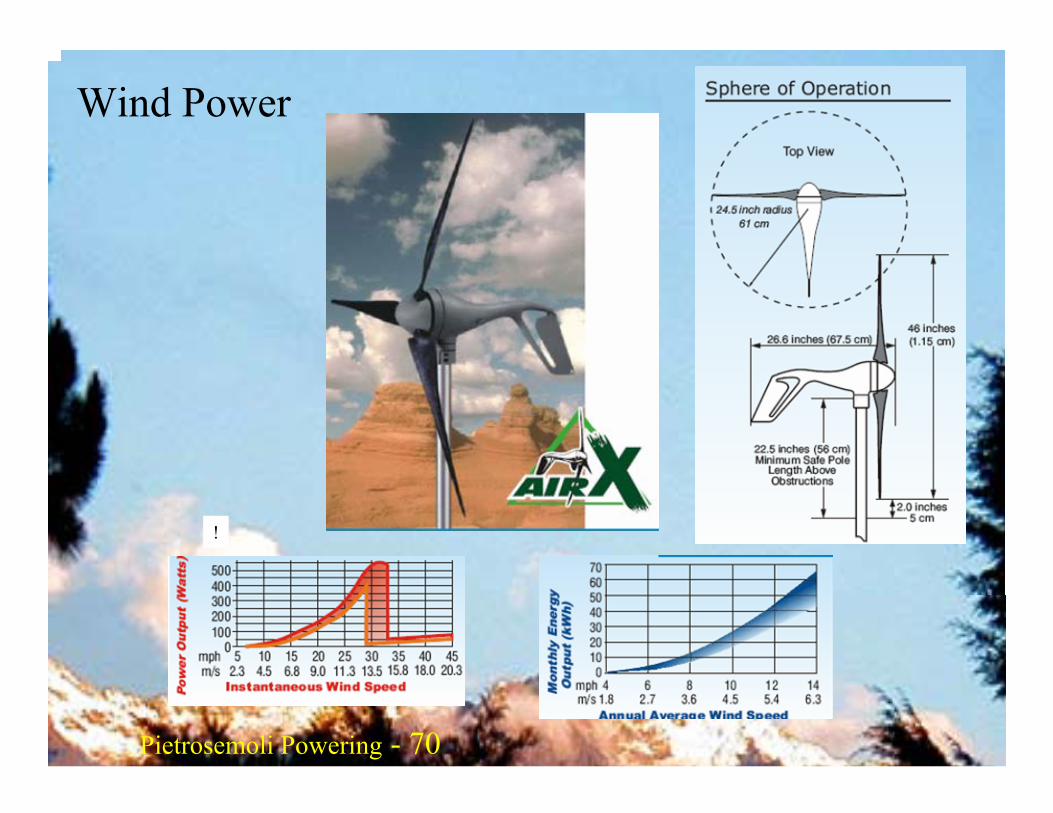
Wind power
A wind generator is a clear option when an autonomous system is being designed for a wireless relay to be built on a hill or mountain. A concern for wind power is that the wind speed must be high enough at a site which maybe surrounded by objects. The average wind speed over the year should be at least 3 - 4 meter per second, and the wind generator should be 6 meters higher than other objects within a distance of 100 meters. A location far awayfrom the coast usually lacks sufficient wind energy to support a wind powered system.
Pietrosemoli Pietrosemoli 70Pietrosemoli Powering - 70
!
Wind Power
Pietrosemoli Pietrosemoli 71Pietrosemoli Powering - 71
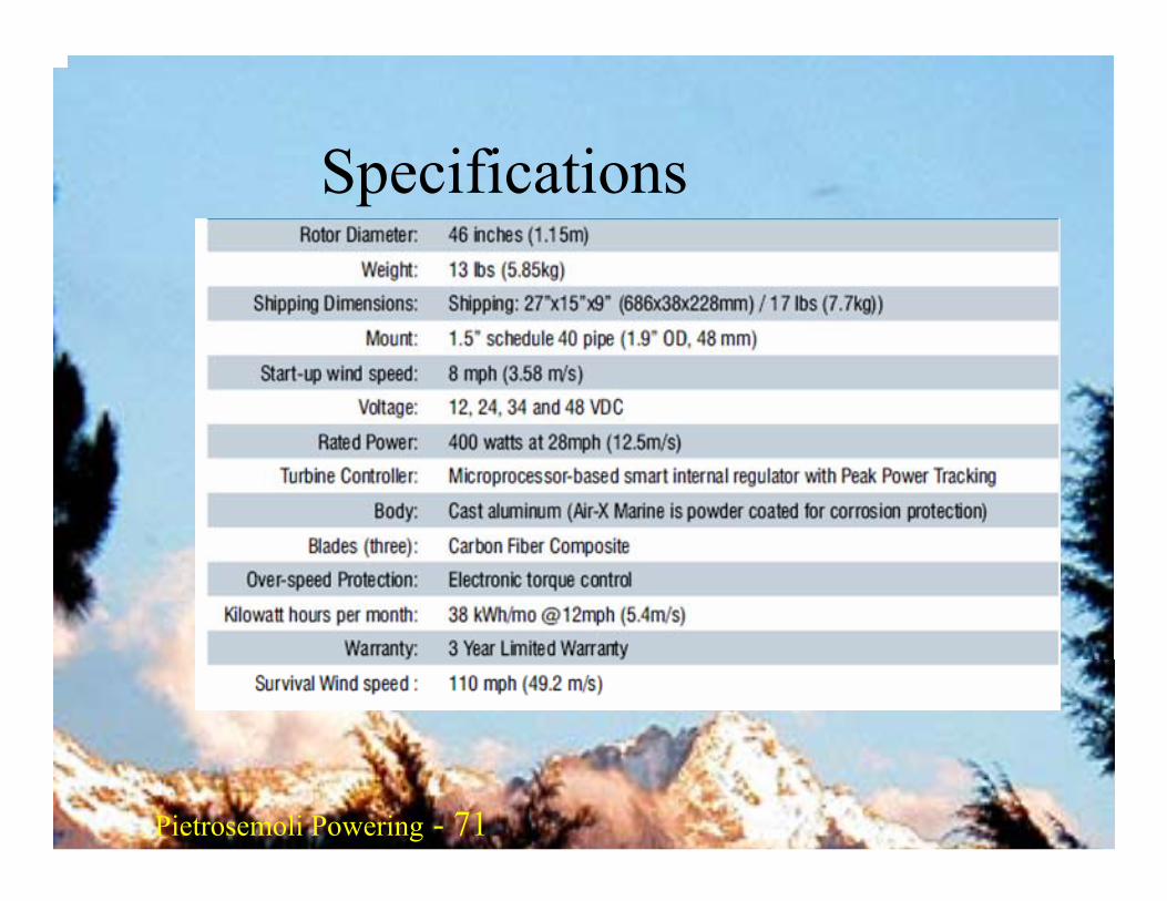
Specifications
Pietrosemoli Pietrosemoli 72Pietrosemoli Powering - 72
The AIR-X Features:Electronics:. The microprocessor based controller provides
voltage regulation, peak power tracking, and quiet, stall control in high winds. It uses a synchronous rectifier bridge which results in cooler, more efficient operation.
Alternator: designed to complement the peak power tracking ability of the control electronics. The strong permanent magnet rotor can be felt in rotating the rotor shaft; a slight “catch” can be felt when spinning the shaft with your fingers. This is normal, and is quickly overcome when the blades begin spinning.
Blades: Manufactured using a precision injection molding process that produces blades of exceptional consistency. The AIR-X blades have an increased tip angle which improves their ability to start rotating, and moves “flutter” to higher wind speeds. The control electronics will slow the blades before the turbine reaches the point of flutter.
Pietrosemoli Pietrosemoli 73Pietrosemoli Powering - 73
The AIR-X Features:
New Yaw Shaft: The yaw shaft is the part of the turbine that mounts to the tower and allows the turbine to rotate into the wind.
Hysteresis Braking: The regulation control circuitry incorporates hysteresis. This will lock the turbine in a silent regulation mode once the batteries are fully charged. The turbine begins producing power again when the battery voltage drops slightly belowfully charged. This means, for a factory set 12V turbine, the turbine will regulate (shut down) when the batteries have reached 14.1V, and will resume charging when the voltage drops to 12.75V.
New Body, New Hub: The AIR-X body is made from a precision casting process that not only enhances fit and finish, but also leads to a stiffer, more durable body. The aluminum casting also acts as a heat sink and transfers heat from the stator and the electronics into the wind flowing past the turbine. The die cast aluminum hub design has been engineered to be the strongest, stiffest hub we have ever produced.
Pietrosemoli Pietrosemoli 74Pietrosemoli Powering - 74
SAFETY PRECAUTIONS
Safety must be the primary concern as you plan the location, installation and operation of the turbine. At all times be aware of electrical, mechanical and rotor blade hazards.1.1 Mechanical HazardRotating blades present the most serious mechanical hazard. The AIR X’s rotor blades are made of very strong thermoplastic. At the tip, the blades may be moving at velocities over 275 miles per hour (440 km/hr). At this speed, the tip of a blade is nearly invisible and can cause serious injury.Under no circumstances should you install the turbine where a
person could come in contact with moving rotor blades.1.2 Electrical HazardsThe internal electronics of the AIR-X prevent open circuit voltages from rising above 20 volts for 12-volt systems or above 40 volts for 24-volt systems.Please note that the inherent personal dangers from electrical current still exist, therefore caution should always be used when connecting this and other electrical devices.
Pietrosemoli Pietrosemoli 75Pietrosemoli Powering - 75

Pietrosemoli Pietrosemoli 76Pietrosemoli Powering - 76
SITINGIn any location, the closer you get to the surface of the earth, the slower the wind speed. This is a result of the friction of the earth and obstacles on the surface. Turbulence caused byobstacles will reduce the efficiency of any wind turbine. Therefore, locate the turbine in a site that has the “cleanest” free-flowing wind possible.Power in the wind is the cubic function of the wind speed. This means that small changes in wind speed can have dramatic changes in output. Each time the wind speed doubles, the power increases eight times! The AIR-X should be mounted on a tower a minimum of 25’ (8 meters) above any surrounding objects within a 500’ (150 m) radius. If this is not possible, then place it as high as you can. If this is a roof top installation, it is important there are no objects around the structure that may block the wind.