Point-to-Point Coherent Optics Coherent Termination Device ...
FieldMaster™
Power/Energy MeterUser Manual
FieldMaster™

FieldMaster™

FieldMaster™
FieldMaster™Power/Energy Meter
User Manual
© 2001 by Coherent, Inc.Part Number 0302-167-00 EA

FieldMaster™

FieldMaster™
Table ofContents
General ............................................................................................... 1Unpacking & Setup ............................................................................ 4Controls & Connections ..................................................................... 6
Front Panel ................................................................................... 6Side Panel ..................................................................................... 7
StartupBattery Installation ....................................................................... 8Turn On ....................................................................................... 9Constrast Adjustment ................................................................. 10Cleaning the Lens ....................................................................... 10
Wavelength Selection ........................................................................ 11Manual Range Selection
Turn On ..................................................................................... 12Range Selection .......................................................................... 13Over Range ................................................................................ 14
Auto Range Selection ........................................................................ 15Offset Entry ...................................................................................... 16Beam Position Display ...................................................................... 17Back Light ........................................................................................ 18Warnings & Alarms
Over Range ................................................................................ 18Over Temperature ...................................................................... 19Low Battery ................................................................................ 19Detector Error ............................................................................ 19Error Messages ........................................................................... 20
CW Detector Heads ......................................................................... 21Pulse Detector Heads ........................................................................ 23Specifications .................................................................................... 24Determining Firmware Version ......................................................... 25Firmware Installation ........................................................................ 25Trouble Shooting .............................................................................. 26Warranty ........................................................................................... 28Ordering/Service Information ........................................................... 29

FieldMaster™

FieldMaster™
1
FieldMaster™ is a rugged, compact, microprocessor driven power andenergy meter that interfaces with the full line of Coherent power andenergy detector heads. FieldMaster is a unique combination of an analogmeter for laser tuning with a precise digital display of power or energy onthe LCD backplane.
FieldMaster can be used with all lasers commonly manufactured today –CW and pulsed, from UV to IR, with rated power form nanowatts tokilowatts – simply by plugging the appropriate sensor head into theconsole.
General
Figure 1. FieldMaster™ Power/Energy Meter

FieldMaster™
2
General(cont’d)
FieldMaster features include:
• Analog Meter Movement - gives fast, smooth feedback for easytuning of lasers.
• Digital Backplane - The FieldMaster’s unique LCD Backplaneprovides precise digital readout of power or energy and indicatorsfor warning or error conditions.
• CW Power Measurement - FieldMaster is compatible with thefull range of Coherent’s SmartDetector Heads, providing powermeasurement capability form 1 nW to 5 kW.
• Pulsed Energy Measurement - FieldMaster provides single pulseor pulse train energy measurement from 0.5 mJ to 10 J (1 µsec-ond pulse).
• Broad Wavelength Range - FieldMaster detectors cover the spec-trum from 0.19 to 10.6 µmeters.
• Smart Detector Technology - FieldMaster detectors employCoherent’s Smart Detector Technology. Each detector head has anEEPROM which stores the characteristics and calibration datafor the detector. This information is read by the FieldMaster con-sole at start-up, eliminating the need to make manual changes tothe console when changing detector heads.
• Beam Alignment Display - Thermal disk CW sensor heads pro-vide a quadrant display of beam position on the sensor. By center-ing the beam on the detector, maximum accuracy can be achieved.
• Ease of Use - FieldMaster controls consist of one clearly labelledrotary switch and three push buttons for wavelength and offsetentry. All adjustments for different detector heads are handledautomatically using Smart Detector Technology.
• Updatable microprocessor architecture - The software control-ling the FieldMaster system can be easily updated to include thelatest developments and enhancements to the instrument.
• Portability - The compact, lightweight console and internal bat-tery pack create a system that is easily transported from lab to lab,or around the world.

FieldMaster™
3
General(cont’d)
• Reliability - The FieldMaster, with its integral cover, is designedto withstand the rigors of travel and regular field use. Coherent’srugged detector head design has been the industry standard formore than 30 years.
• Accuracy - The combination of Smart Detector Technology,microprocessor wavelength correction, and accurate beam posi-tioning information create a highly accurate laser measurementsystem.

FieldMaster™
4
FieldMaster console is shipped in foam inserts. When ordered togetherwith Detector Heads, they are normally shipped in the same carton as theFieldMaster console. In addition to the console and detector head, thecarton contains the AC adaptor with cord and the user manual. The op-tional Soft Case (if ordered) and all additional detector heads are shippedin separate cartons. Batteries are installed in the FieldMaster prior to ship-ment.
Visually check cartons and contents for damage before unpacking. AdviseCoherent of any damage immediately and a Returned Material Authori-zation will be issued for the instrument (see page 29 for service).
Remove all items from carton. If desired, plug the AC Adaptor into 110VAC (in Europe, 220 VAC) outlet and the 9V Input socket on the leftside of the FieldMaster (see Figure 2). Plug the detector head into theDB25 socket on the left side of the console. The unit is now ready to use.
Figure 2. Initial Setup
0
0
1
12 2
3
3
45 6
7
8
9
10
FIELDMASTER
MANUAL
AUTO
OFF
OFFSET
λ SELECT
Power SocketRegulated 9 VDC 0.4A Power Supply (Use only Coherent AC Adapter)
DB25 Detector Socket(Use only Coherent SmartHead Technology Detectors)

FieldMaster™
5
Controls &Connections
Front PanelThe front panel of the FieldMaster has a rotary SELECTOR SWITCHand three push button controls.
The SELECTOR SWITCH has four positions. In the bottom position,unit is turned off. The next position up, labelled AUTO, turns the uniton in the auto ranging mode. In the next position, labeled MANUAL,the unit is on the manual ranging mode. The top position, labelled λSELECT, is the wavelength selection mode.
Figure 3. Front Panel Controls
0
1
23
4 5 67
8
9
10
0
1 2
3
MANUAL
AUTO
OFFOFFSET
F I E L D M A S T E R
λ SELECT
Wavelength/Range SelectionButtons
Offset EntryButton
SelectorSwitch

FieldMaster™
6
Controls &Connections(cont’d)
To the right of the SELECTOR SWITCH are three pushbutton controls.The top two (shaped like arrows are WAVELENGTH/RANGE SELEC-TION BUTTONS. These are used to change the wavelength up anddown in the wavelength selection mode or to change the power or energyrange up and down in the manual ranging mode.
The bottom button (rectangular shaped) is the OFFSET ENTRY BUT-TON. It is used to enter current power or energy reading as an offsetamount and zero the meter reading when in AUTO or MAN mode. Inλ Select mode, the OFFSET ENTRY BUTTON adjusts the liquid crys-tal display contrast. FieldMaster is shipped with the contrast at the middleof the range. To change contrast, push the OFFSET ENTRY BUTTON.Each time the OFFSET ENTRY BUTTON is pushed, contrast is in-creased 4%. After maximum contrast is achieved, the next push of thebutton will return the contrast to minimum. The LCD screen can effec-tively be turned off by adjusting contrast to minimum.
FieldMaster™
7
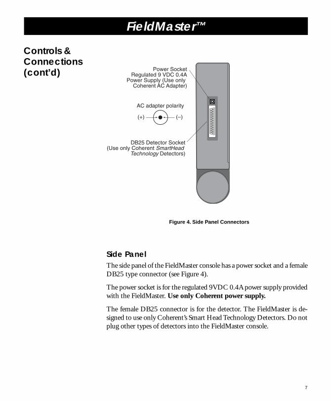
Figure 4. Side Panel Connectors
Side PanelThe side panel of the FieldMaster console has a power socket and a femaleDB25 type connector (see Figure 4).
The power socket is for the regulated 9VDC 0.4A power supply providedwith the FieldMaster. Use only Coherent power supply.
The female DB25 connector is for the detector. The FieldMaster is de-signed to use only Coherent’s Smart Head Technology Detectors. Do notplug other types of detectors into the FieldMaster console.
Controls &Connections(cont’d) Power Socket
Regulated 9 VDC 0.4APower Supply (Use only
Coherent AC Adapter)
DB25 Detector Socket(Use only Coherent SmartHead
Technology Detectors)
(+) (–)
AC adapter polarity

FieldMaster™
8
Startup Replace batteries with standard 9V transistor radio batteries (DuracellMN1604 or ID1604 or equivalent). FieldMaster is fully functional withonly one battery connected. Use 2 batteries for maximum working lifebattery change.
Press hereBatteryCompartment
Back of LaserMate
Press down and push batterycover out in direction indicatedto open battery compartment
Figure 5. Battery Installation
Battery InstallationTo start the FieldMaster either batteries must be installed (see Figure 5) orthe AC adapter must be plugged into the socket on the left side of theconsole (see Figure 4).

FieldMaster™
9
Figure 6. Initial Turn On
Turn OnTurn the SELECTOR switch to AUTO. All screen features will bedisplayed for approximately 7 seconds while the unit is performing thefollowing self tests (see Figure 6):
Internal test of processor, memory and software. If theFieldMaster fails the self test, an error message will be displayed.In case of failure, no further tests will be made and the system willnot operate. Note the failure code that is displayed. TURN OFFPOWER AND CONTACT COHERENT OR YOUR LOCALREPRESENTATIVE (See Service and Warranty section page 29).
Startup(cont’d)
0
1
23
4 5 67
8
9
10
0
1 2
3
OFFSETDETECTOR
ERROR
mkJW
BATT
MANUAL
AUTO
OFFOFFSET
F I E L D M A S T E R
n
λ SELECT
SelectorSwitchto AUTO

FieldMaster™
10
Check for detector head. A query will be sent to the EEPROMin the Detector Head. If no head is plugged in, the message“DETECTOR ERROR” will be displayed. A Detector Head mustbe plugged in.
When the self tests are completed and the parameters for the detectorhave been loaded, the current power or energy reading and the BeamPosition Indicator (Thermal Disc sensors) or the Pulse Received Indicator(pulsed detectors will be displayed.
Contrast AdjustmentFieldMaster is shipped with the LCD contrast at the middle of the range.To change contrast, turn the SELECTOR SWITCH to the λ SELECTposition (see Figure 7). Push the OFFSET ENTRY BUTTON is pushed,contrast is increased 4%. After maximum contrast is achieved, the nextpush of the button will return the contrast to minimum. The LCD screencan effectively be turned off by adjusting contrast to minimum.
Cleaning the LensTo reduce the effect of static electricity on the analog meter movement,please clean the lens with the enclosed anti-static cloth only.
Startup(cont’d)

FieldMaster™
11
WavelengthSelection
Figure 7. Wavelength Selection
Turn selector switch to l SELECT (see Figure 7). The digital display willshow the selected wavelength in n (nanometers) or µ (micrometers). Tochange the selected wavelength, use the WAVELENGTH/RANGE SE-LECTION buttons to the right of the selector switch. To move to a longerwavelength, press the top button (the arrow pointing up). To move to ashorter wavelength, press the bottom button (the arrow pointing down).Pressing and releasing the button will cause the range to change one in-crement (see below). Holding the button down will cause the wavelengthto change continually at an increasing rate. New wavelength will be storedin memory and retained when power is turned off.
The size of the incremental change in the wavelength depends on thecurrent wavelength. From 190 to 1000 nm the incremental change is 10nm. Above 1 µm incremental change is 0.1 µm.
Wavelength maximum and minimum are determined by the detector.These parameters are read from the EEPROM in the detector at startup.The wavelength display will not go below the minimum or above themaximum for the detector head in use.
0
1
23
4 5 67
8
9
10
0
1 2
3
MANUAL
AUTO
OFFOFFSET
F I E L D M A S T E R
n
λ SELECT
IncreaseWavelength
CurrentWavelength
DecreaseWavelength
Offset EntryButton
Selector Switchto λ SELECT
UnitsIndicator

FieldMaster™
12
ManualRangeSelection
Figure 8. Manual Range Selection
Turn OnTurn the Selector Switch to MANUAL. The FieldMaster will be in thelowest range for the detector when it is first turned on if the detector headis CW. It will be in the highest range for the detector when first turned onif the detector head is pulsed.
Note: When using a pulse detector, the FieldMaster will display an erro-neous reading when it is switched from manual to autorange mode andvice versa until the next pulse occurs. This is due to the “switch-bounce”when the mode selector switch in changed. When the system is initiallyswitched on, several pulses will be required before an energy level is dis-played in order to set the appropriate amplifier gain range.
0
1
23
4 5 67
8
9
10
0
1 2
3
W
MANUAL
AUTO
OFFOFFSET
F I E L D M A S T E R
λ SELECT Up SelectionButton
Down SelectionButton
Selector Switchto MANUAL
m

FieldMaster™
13
Range SelectionTo select a new range, press the UP or DOWN SELECTION BUTTON.The first time the button is pushed, the current range will be displayed.This display will be maintained for 2 seconds. If the SELECTION BUT-TON is pressed again during the 2 second interval the range is beingdisplayed, the range will be changed to the next higher (if UP) or lower (ifDOWN) range. After 2 seconds, the range display is replaced by the dis-play of the current power/energy reading. If the FieldMaster is indicatingan over range condition, pressing the UP SELECTION BUTTON willimmediately change the range to the next higher range. Range can beincreased to the limit of the detector head currently in use.
ManualRangeSelection(cont’d)

FieldMaster™
14
Figure 9. Over Range Indication
Over RangeDuring operation in the Manual Range Mode, if the power exceeds theselected range, a warning tone will sound every 0.5 seconds and the dis-play will flash the top power reading of the selected range. To change therange upward, press the UP SELECTION BUTTON once.
When changing to a lower range, if the current power level is above themaximum of the range selected, the warning tone will begin soundingand the display will flash the top value of the selected range.
ManualRangeSelection(cont’d)
0
1
23
4 5 67
8
9
10
0
1 2
3
W
MANUAL
AUTO
OFFOFFSET
F I E L D M A S T E R
λ SELECT Up SelectionButton
Display flashes top reading
of current range
Tone sounds every 0.5 seconds

FieldMaster™
15
ManualRangeSelection(cont’d)
Turn the selector switch to AUTO (see Figure 10). In pulse mode, thesystem will require several pulses before an energy level is displayed inorder to set the appropriate amplifier gain range. The digital display willdisplay the proper power and units for any power/energy within the mini-mum and maximum of the head plugged in. The display range for theanalog display will automatically switch up to the next range when thecurrent reading reaches 95% of the current range. The display range willswitch down when the current power/energy reading reaches 95% of thenext lower range.
Note: When using a pulse detector, the FieldMaster will display an erro-neous reading when it is switched form manual to autorange mode andvice versa until the next pulse occurs. This is due to the “switch-bounce”when the mode selector switch is changed. When the system is initiallyswitched on, several pulses will be required before an energy level is dis-played in order to set the appropriate amplifier gain range.
Figure 10. Auto Range Selection
0
1
23
4 5 67
8
9
10
0
1 2
3
J
MANUAL
AUTO
OFFOFFSET
F I E L D M A S T E R
n
λ SELECT
Selection Switchto AUTO

FieldMaster™
16
Offset Entry
Figure 11. Offset Entry
Pressing the OFFSET button (the lowest button to the right of the Selec-tor Switch) enters the current power/energy reading as an offset value andzeros the digital and analog power displays. (This can also be used tocancel ambient light levels for low power applications.) When an offsethas been entered, the word OFFSET is shown in the upper left corner ofthe display (see Figure 11). If an offset has already been entered, pressingOFFSET cancels the old offset and adds the new offset value to the digi-tal and analog displays. In order to achieve specified accuracy for the headbeing used, ambient light must be cancelled using OFFSET.
The OFFSET function operates only with CW detectors. When a pulseddetector is plugged in, the OFFSET button is not functional.
0
1
23
4 5 67
8
9
10
0
1 2
3
OFFSET m W
MANUAL
AUTO
OFFOFFSET
F I E L D M A S T E R
λ SELECT
Offset EntryButton
Offset enteredmessage

FieldMaster™
17
0
1
23
4 5 67
8
9
10
0
1 2
3
W
MANUAL
AUTO
OFFOFFSET
F I E L D M A S T E R
λ SELECT
Beam Position Display (Beam Centered)
Beam PositionIndications
(assume normal orientation of the head)
Beam high on detector
Beam to right on detector
Beam low on detector
Beam to left on detector
Two quardrants can beshown simultaneously (e.g. beam high and
to the left)
Figure 12. Beam Position Display
In order to achieve the greatest accuracy with Thermal Disk CW PowerSensors, the beam must be centered on the sensor disk. To assist in center-ing, beam position on the detector is indicated in the upper right of theFieldMaster display (see Figure 12). Note that this display is not activewith pyroelectric (LM- #), silicon sensor (LM-2) detectors, or LM-1 ther-mal sensor.
Move the detector head until the beam position display indicates the beamis striking the center of the detector.
Beam PositionDisplay

FieldMaster™
18
Back Light The FieldMaster features a read back light. This feature is automaticallyactivated when the AC Adapter is used, and is inactive when batteries areused. There is no on/off or level control for the backlight.
Warnings& Alarms
Figure 13. Over Range Indication
0
1
23
4 5 67
8
9
10
0
1 2
3
W
MANUAL
AUTO
OFFOFFSET
F I E L D M A S T E R
λ SELECT
Display flashes top reading
of current range
Over selected range
Single tone every0.5 second
Over detector range
Double tone every0.5 second
Over RangeDuring operation in the Manual Range Mode, if the power goes abovethe top of the selected range, a warning tone will sound every 0.5 secondsand the display will flash the top power reading of the selected range (seeFigure 13). To change the range upward, press the UP SELECTIONBUTTON once. If the power is over the maximum for the detector, theaudible alarm will be a double tone every 0.5 seconds.
When changing to a lower range, if the current power level is above themaximum of the range that is selected, the warning tone will begin sound-ing and the display will flash the top value of the selected range.

FieldMaster™
19
Warnings& Alarms(cont’d)
0
1
23
4 5 67
8
9
10
0
1 2
3
DETECTORERROR
k W
BATT
MANUAL
AUTO
OFFOFFSET
F I E L D M A S T E R
λ SELECT
Low BatteryIndicatorOver
TemperatureIndicator
Detector ErrorIndicator
Figure 14. Warning Indicators
Over TemperatureIf the detector temperature is above its specified maximum, the over tem-perature indicator will appear on the display (see Figure 14).
Low BatteryIf the battery is below 5% of its specified life, the low battery indicatorwill appear in the lower right of the display (see Figure 14). Approxi-mately 1 hour battery life remains.
Detector ErrorIf the FieldMaster console is turned on with no detector or a defectivedetector plugged in, or if the head is unplugged, the messageDETECTOR ERROR will appear in the upper left of the display (seeFigure 14).

FieldMaster™
20
Warnings& Alarms(cont’d)
0
1
23
4 5 67
8
9
10
0
1 2
3
ERROR
MANUAL
AUTO
OFFOFFSET
F I E L D M A S T E R
λ SELECT
Error CodeErrorIndicator
Figure 15. Error Messages
Error MessagesIn the event of head or console failure, the following diagnostic errorcodes may be displayed (see Figure 15).
ErrorCode Reason
0 ROM (checksum)
1 RAM (memory error)
2 INTERNAL BUS
3 DAC RANGE (unable to correct amp offset)
4 LOW BATTERY (below 5.6 volts)
5 ANALOG EEPROM (checksum)
6 DETECTOR EEPROM (checksum)
7 UNKNOWN DETECTOR (unable to decode EEPROM)
8 NON-SUPPORTED DETECTOR
9 DETECTOR INCOMPATIBILITY
FieldMaster™
21
CW DetectorHeads
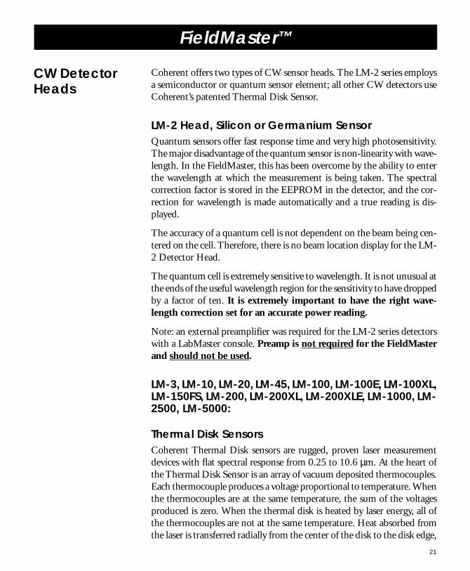
Coherent offers two types of CW sensor heads. The LM-2 series employsa semiconductor or quantum sensor element; all other CW detectors useCoherent’s patented Thermal Disk Sensor.
LM-2 Head, Silicon or Germanium SensorQuantum sensors offer fast response time and very high photosensitivity.The major disadvantage of the quantum sensor is non-linearity with wave-length. In the FieldMaster, this has been overcome by the ability to enterthe wavelength at which the measurement is being taken. The spectralcorrection factor is stored in the EEPROM in the detector, and the cor-rection for wavelength is made automatically and a true reading is dis-played.
The accuracy of a quantum cell is not dependent on the beam being cen-tered on the cell. Therefore, there is no beam location display for the LM-2 Detector Head.
The quantum cell is extremely sensitive to wavelength. It is not unusual atthe ends of the useful wavelength region for the sensitivity to have droppedby a factor of ten. It is extremely important to have the right wave-length correction set for an accurate power reading.
Note: an external preamplifier was required for the LM-2 series detectorswith a LabMaster console. Preamp is not required for the FieldMasterand should not be used.
LM-3, LM-10, LM-20, LM-45, LM-100, LM-100E, LM-100XL,LM-150FS, LM-200, LM-200XL, LM-200XLE, LM-1000, LM-2500, LM-5000:
Thermal Disk SensorsCoherent Thermal Disk sensors are rugged, proven laser measurementdevices with flat spectral response from 0.25 to 10.6 µm. At the heart ofthe Thermal Disk Sensor is an array of vacuum deposited thermocouples.Each thermocouple produces a voltage proportional to temperature. Whenthe thermocouples are at the same temperature, the sum of the voltagesproduced is zero. When the thermal disk is heated by laser energy, all ofthe thermocouples are not at the same temperature. Heat absorbed fromthe laser is transferred radially from the center of the disk to the disk edge,

FieldMaster™
22
thus creating a temperature gradient. Due to this temperature gradient,the sum of the voltages produced by the thermocouples is proportional tothe amount of laser energy striking the disk. The higher the laser energy,the higher the net voltage output.
The radially symmetrical thermocouple array is theoretically insensitiveto beam position (assuming the beam is totally within the array). As apractical matter, minor differences in the deposited thermocouples leadto variations in reading as the beam position is moved around the sensordisk. The sensor head is calibrated for a Gaussian mode laser beam inci-dent on the center of the thermal disk. The accuracy of the sensor head istherefore dependent on the beam type, size, and on the beam being cen-tered on the disk. The Beam Position Display on the FieldMaster enablesthe user to center the beam precisely on the sensor to achieve maximumaccuracy from the sensor head.
If water cooling is required, the detector should not be placed in thebeam without specified cooling water flow.
CW DetectorHeads(cont’d)
Laser DamageAll sensors will be damaged if the specified maximum power densityis exceeded. Check the maximum power density for your detectorhead. Expand the beam if necessary.

FieldMaster™
23
Pulse DetectorHeads
LM-P5, LM-P10, LM-P10i, LM-P5LP, LM-P10LPPyroelectric DetectorsCoherent pulse energy detectors feature a crystalline pyroelectric materialwith proven advantages over other ceramic materials:
Better surface quality, providing better spatial uniformity.
Lower temperature coefficient, providing greater accuracy andstability.
Lower piezoelectric coefficient, eliminating microphonic noise.
Lower capacitance, allowing higher rep rates.
Pyroelectric Detector OperationAll pyroelectric detectors act as pulse integrators. The pulse integrationoccurs in the black absorbing coating as a result of its thermal capaci-tance. This assumes that the pulse is much shorter than the thermal timeconstant of the coating. In either case, the pulse detector produces a volt-age whose peak value is directly proportional to the radiant energy.
Laser DamageAll sensors will be damaged if the specified maximum energy densityis exceeded. Check the maximum energy density for your detectorhead. Expand the beam if necessary.

FieldMaster™
24
Sensor Types Supported: Thermopile, power measurement. Photodiode, powermeasurement. Pyroelectric, pulse energy measurement.See sensor data for details.
Ranging: Automatic or manual, user selectable. Useful ranges forany supported detector head are limited by headspecifications only.
Offset: All ranges except top range can be offset by one fullrange.
Wavelength Correction: Readings can be frequency corrected over the range190 nm to 10.6 µm Correction frequency is stored inpermanent memory.
Display: Three digit liquid crystal display (LCD) and conven-tional moving coil meter. Contrast can be adjusted viapush buttons. Contrast setting is stored in permanentmemory. Backlit with AC Adaptor connected. Backlightcolor is red. Backlighting disabled when operating onbattery power.
Power Requirements: • AC operation
65-125 VAC 50/60 Hz 130-250 VAC 50/60 Hz10 VA maximum 7.5 VA maximum1.5 VA typical 1.5 VA typicalAdapter 0214-047-00 Adapter 0217-048-00
• DC Operation
Uses 2 standard 9 V transistor radio batteries. Unit isfully functional with only one battery connected. Use 2batteries for maximum working life before batterychange. Low battery condition is indicated at 5% ofbattery life remaining.
Working life of batteries:8 hours with 2 Duracell MN1604 or ID16044 hours with 1 Duracell MN1604 or ID1604
Size: 7.6" long x 4.6" wide x 1.8" thick, when closed.(19.3 cm x 11.7 cm x 4.6 cm)
Weight (with batteries): 26 ounces (737 gms), with batteries
Console Accuracy: 2%. Net accuracy with any head ishead accuracy + instrument accuracy
Response Time: A function of sensor response speed. See sensor data.
Safety Features: Sensor over-temperature and sensor over-range alarmedvisually and audibly.
OperatingTemperature Range: 5°C to 40°C
Specifications

FieldMaster™
25
DeterminingFirmwareVersion
FirmwareInstallation
Turn the FieldMaster on with no head connected. The messageDETECTOR ERROR will appear in the upper left of the display. Thenumerals in the center of the display will show any error conditions as-#-. If no errors exist, either three dashes, “---”, will be displayed forfirmware versions older than Revisions 1.2, or, for versions 1.2 and later,the version number will be shown (e.g. 1.20). Newer detector heads (e.g.the LM-2IR) may require current firmware to operate. For firmwareupdates, contact Service (see page 29).
Exercise ESD protectivemeasures when working on theFieldMaster. The unit will notrequire re-calibration after thischange, provided the existingcalibration is current. Wheninstallation is completed, returnold EPROM to CoherentAuburn Division.
1. Place the FieldMaster facedown, remove battery coverand disconnect batteries.(Drawing 1).
2. Remove two screws in thebattery compartment.(Drawing 2).
3. Carefully separate case halvesby pressing in on case frontat the location of the catches(Drawing 3), to release them.Leave case front in position,face down, to protect delicateanalog meter.
Battery Cover
Two screws in battery compartment
Tabs inCase Back
Case Back
Eprom P/N 0302-117-01FW Revision 1.0
CaseFront
Catches
Catch
1
2
3

FieldMaster™
26
TroubleShooting
Problem Probable Cause SolutionDead battery, AC Adapternot plugged in
FieldMaster display doesnot turn on
Plug in AC adapter orreplace batteries withDuracell MN1604 orID1604 9 V batteries orequivalent (unit willoperate on one 9 Vbattery, use 2 batteriesfor maximum service life)
Defective selector switch Call service
No detector plugged in
EEPROM is detector isdefective or cable is broken
DETECTOR ERRORmessage on display whenunit is turned on
Plug in detector
Call service
In Manual Range mode, thecurrent power/energy ishigher than the current range
Display is flashing andtone is sounding every0.5 seconds
Press UP Range SelectionButton to increase range
Current energy/power ishigher than the detector israted for
Display is flashing anddouble tone is soundingevery 0.5 seconds
Turn energy/powerdown, attenuate beam,or remove detector frombeam
Batteries are low (low batterycondition is indicated at 5%of useful battery life
BATT symbol isdisplayed on lower rightof screen
Plug in AC adapter orreplace batteries withDuracell MN1604 orID1604 9 V batteries orequivalent (unit willoperate on one 9 Vbattery, use 2 batteriesfor maximum service life)
Detector head is overspecified maximumtemperature
Over Temperaturesymbol is displayed onlower left of screen
Turn energy/powerdown, attenuate beam,or remove detector frombeam
Insufficient cooling water(water cooled heads only)
Check cooling watertemperature, flow.Check hoses for kinks.

FieldMaster™
27
TroubleShooting(cont’d)
FieldMaster displayerror code:
Backlight not on AC Adapter not plugged in Backlight only workswhen operating on ACPower. Plug in ACAdapter
-9- DETECTORINCOMPATIBILITY
Call service
-8- NON-SUPPORTEDDETECTOR
Use compatible detector
-7- UNKNOWN DETECTORunable to decode EEPROM
Call service
-6- DETECTOR EEPROM(checksum)
Call service
-5- ANALOG EEPROM(checksum)
Call service
-4- Battery below 5.6 volts Plug in AC Adapter orreplace batteries withDuracell MN1604 orID1604 9 V batteries orequivalent (unit willoperate on one 9 Vbattery, use 2 batteriesfor maximum service life)
-3- DAC Range (unable tocorrect amp offset)
Call service
-2-
-1- RAM (memory error) Call service
ROM (checksum) Call service-0-
Problem Probable Cause Solution

FieldMaster™
28
Warranty The seller warrants to the original Buyer each item manufactured by it to befree from defects in material and workmanship for a period of time and un-der such conditions as specified in the Seller’s warranty for the individualproduct, or for twelve (12) months from delivery if a warranty for the indi-vidual product is not specified. Major sub-systems manufactured by otherfirms but integrated into the Seller’s systems are covered by the originalManufacturer’s warranty. The Seller’s liability under valid warranty claims islimited to repair or replacement at the Seller’s plant or the Buyer’s location, allat the option of the Seller.
THE FOREGOING WARRANTY IS EXCLUSIVE AND IN LIEU OFALL OTHER WARRANTIES, WHETHER WRITTEN, ORAL OR IM-PLIED AND SHALL BE THE BUYER’S SOLE REMEDY AND THESELLER’S SOLE LIABILITY ON CONTRACT OR WARRANTY OROTHERWISE FOR THE PRODUCT. THE SELLER’S DISCLAIMS ANYIMPLIED WARRANTY OR MERCHANTABILITY OR FITNESS FORPURPOSE.
All claims under warranty must be made promptly after occurrence of cir-cumstances giving rise thereto, must be received within the applicable war-ranty period by the Seller, and shall be subject to the terms and conditionsstated herein. Such claims should include the product serial number, the dateof shipment, and a full description of the circumstances giving rise to theclaim. Before any products are returned for repair and/or adjustment, autho-rization for the Seller for the return and instructions as to how and wherethese Products should be shipped must be obtained. Any product returned tothe Seller for examination and/or warranty repair shall be sent prepaid via themeans of transportation indicated as acceptable by the Seller. The Seller re-serves the right to reject any warranty claim on any item that has been shippedby non-acceptable means of transportation. When any product is returnedfor examination and inspection, or for any other reason, the Buyer and itsshipping agency shall be responsible for all damage resulting from improperpacking or handling, and for loss in transit, notwithstanding any defect ofnon-conformity in the Product. In all cases, the Seller has sole responsibilityfor determining the cause and nature of failure, and the Seller’s determinationwith regard thereto shall be final.
If it found the Seller’s Product has been returned without cause and is stillserviceable, the Buyer will be notified and the Product returned at the Buyer’sexpense, in addition, a charge for testing and examination may, in the Seller’ssole discretion, be made on products returned.

FieldMaster™
Thirty years of innovationCoherent has been the world leader in the manufacture of lasers, andthe instruments to measure them, for over thirty years. Coherent offerscomplete solutions for laser characterization, process control, and systemdesign.
You may contact your local representative or Coherent for further infor-mation regarding these items. Call and ask for one of our customer carespecialists. Purchase orders may be placed by phone, fax or mail.
Sales &ServiceInformation
FranceDomaine Technologiquede SaclayBâtiment AZUR4, rue René Razel91892 Orsay CedexFranceTel: +33-1-60 19 40 40Fax: +33-1-60 19 40 00
JapanToyo MK Building7-2-14 ToyoKoto-kuTokyo 135JapanTel: +81 (0) 3 5635 8680Fax: +81 (0) 3 5635 8681
United States2303 Lindbergh StreetAuburn, CA 95602Sales Tel: 1-800-343-4912Sales Fax: 530-889-5366Service Tel: (530) 888-5062Service Fax: (530) 889-5262
United Kingdom28 St. Thomas PlaceCambridgeshire Business ParkEly, Cambs. CB7 4EXUKFree Phone: 0800 515801Tel: +44 (0) 1353 658848Fax: +44 (0) 1353 659110
GermanyDieselstraße 5bD-64807DieburgGermanyTel: +49-6071-968-0Fax: +49-6071-968-499

FieldMaster™

FieldMaster™

FieldMaster™

FieldMaster™

FieldMaster™
www.CoherentInc.com
United States2303 Lindbergh StreetAuburn, CA 95602Toll Free: 1-800-343-4912Tel: 530-889-5365Fax: 530-889-5366
United Kingdom28 St. Thomas PlaceCambridgeshire Business ParkEly, Cambs. CB7 4EXUKFree Phone: 0800 515801Tel: +44 (0) 1353 658848Fax: +44 (0) 1353 659110
GermanyDieselstraße 5bD-64807DieburgGermanyTel: +49-6071-968-0Fax: +49-6071-968-499
FranceDomaine Technologique de SaclayBâtiment AZUR4, rue René Razel91892 Orsay CedexFranceTel: +33-1-60 19 40 40Fax: +33-1-60 19 40 00
JapanToyo MK Building7-2-14 ToyoKoto-kuTokyo 135JapanTel: +81 (0) 3 5635 8680Fax: +81 (0) 3 5635 8681