Power Transmission Belts Engineering Guide Habasit– Solutions in ...
64
Services Media No. 6026 Power Transmission Belts Engineering Guide Habasit – Solutions in motion
Transcript of Power Transmission Belts Engineering Guide Habasit– Solutions in ...

ServicesMedia No. 6026
Power Transmission BeltsEngineering Guide
Habasit–Solutions in motion

Product liability, application considerationsIf the proper selection and application of Habasit products are not recommended by an authorized Habasit sales specialist, the selection and application of Habasit products, including the related area of product safety, are the responsibility of the customer. All indications / information are recommendations and believed to be reliable, but no representations, guarantees, or warranties of any kind are made as to their accuracy or suitability for particular applications. The data provided herein are based on laboratory work with small-scale test equipment, running at standard conditions, and do not necessarily match product performance in industrial use. New knowledge and experiences can lead to modifi cations and changes within a short time without prior notice. BECAUSE CONDITIONS OF USE ARE OUTSIDE OF HABASIT’S AND ITS AFFILIATED COMPANIES’ CONTROL, WE CANNOT ASSUME ANY LIABILITY CONCERNING THE SUITABILITY AND PROCESS ABILITY OF THE PRODUCTS MENTIONED HEREIN. THIS ALSO APPLIES TO PROCESS RESULTS / OUTPUT / MANUFACTURING GOODS AS WELL AS TO POSSIBLE DEFECTS, DAMAGES, CONSEQUENTIAL DAMAGES, AND FURTHER-REACHING CONSEQUENCES.

3
6026BRO.PTB-en0612HQR
Contents
IntroductionThe history of flat belt power transmission 4The flat belt as a versatile machine element 6The flat belt compared to the V-belt drive 7
Power transmission belts HabaDRIVE®The belt concept 8Product key data 9
Belt selection and calculationGathering the drive data 10Selection of the optimal belt type 11Calculation by POWER-SeleCalc 12
Technical belt data Belt length 13 Tensile force for 1% elongation (k1% value) 16Shaft load 17Nominal peripheral force 17
Design guidelinesGeneral drive design 18Flat belt pulleys 19Bearings 23Tensioning device 24
Special flat belt drivesTangential belt drive 26Spindle tape drive 346Live roller conveyor drive 37Multi pulley drive (power branching) 41Angular drive (mule drive) 42Half-cross drive 43
Belt fabricationFlexproof joining system (finger joint) 45Thermofix joining system 46
Belt InstallationSafety regulations 47First-time installation 48 Installation of strong belts; re-installation 50
Belt maintenance and trouble-shootingBelt maintenance 51Trouble-shooting 52
Belt Storage and HandlingStorage conditions 54
Symbols and units 56
Questionnaire: power transmission belts 58Questionnaire: tangential belts 59
The Habasit Solution 63
Contacts 64

4
6026BRO.PTB-en0612HQR
IntroductionThe history of fl at belt power transmission
Belts, ropes and chains have been used as traction devices for centuries. Babylonians and Assyrians used chains for the first time for water drawing machines. By 1430, endless rope haulage was used to drive grinding devices, and in the drawings of Leonardo da Vinci (1452 to 1519) link chains are shown.
During the course of industrialization, which started with the invention of the steam engine in the 18th century, the power transmission drive with flat belts made of chrome leather became the indispensable basis for industrial production. The power generated centrally by the steam engine was transmitted to individual production machines via long transmission shafts.
Leonhard Euler (mathematician, 1707–1783) authored the first theoretical essays on the traction mechanism. Based on these essays, the engineer Johann Albert Eytelwein (1764–1848) established his rope friction equation in 1808, an equation that is still indispensable for calculating frictionally engaged drives. At the same time, traction mechanisms continued to develop at a rapid pace.
Due to the introduction of the electric motor, its application as an individual drive, and the drawbacks of the leather belt (friction degradation; waning tension; vibration-stimulation, noise, and accident-prone mechanical joints), the power transmission belt was temporarily displaced.
The invention of polyamide in the Second World War presented an opportunity to Fernand Habegger (founder of Habasit AG Switzerland, 1921–1992) to create a flat belt with stable and predictable elastic characteristics which could be made endless by a glued joint. At that time, chrome leather was adhered to the polyamide traction layer as a friction cover.
Today’s modern, fully synthetic, high-duty power transmission flat belts are equipped with a strong and resilient traction layer made of polyamide, polyester or aramide, and with wear-resistant, oil and grease resistant friction covers made of NBR-rubber (elastomer) that provide a high degree of consistent friction between belt and pulleys.
High efficiency synthetic flat belts are currently being used in all areas of power transmission technology due to their versatility, energy saving properties, and outstanding reliability.

5
6026BRO.PTB-en0612HQR
IntroductionThe history of fl at belt power transmission
Examples of power transmission flat belt applications:
Flat belt driven 160 ton press Tangential belt drives on spinning machines
Flat belt driven industry fan Flat belt driven live roller conveyor
Twisted flat belt drive on a textile machine

6
6026BRO.PTB-en0612HQR
The power transmission flat belt can be used in many forms of power transmission. Basically it is known as a two pulley drive (open drive), consisting of a driving pulley, a driven pulley and the belt.
However, the flat belt can be used in a great number of design variations. Here some typical examples:
Details are available in the chapter on “Special flat belt drives” starting on page 26.
= driving pulley
Angular drive Half-cross drive Spindle tape drive
Two pulley drive (open drive) Multi pulley drive (power branching)
Live roller conveyor driveTangential belt drive
IntroductionThe flat belt as a versatile machine element

7
6026BRO.PTB-en0612HQR
IntroductionThe flat belt compared to the V-belt drive
Based on the fundamental technical differences, the flat belt drive offers considerable benefits compared to the V-belt drive.
The V-belt drive
Frictional engagement between the lateral wedge surfaces require a large cross-section and high stiffness of V-belts
High energy loss due to cyclic bending
Frictional engagement on the outer pulley surface require only a small cross-section and make fl at belts very fl exible
Negligible energy loss due to cyclic bending
The fl at belt drive
V-belts are wedging in grooves and pulling out from grooves
Energy loss and high wear
No grooves required, consequently no wedging in and pulling out from grooves
No energy loss and negligible wear
Consequential benefi ts of the fl at belt drive:• Higher effi ciency, hence considerable energy savings• Longer service life of belts and pulleys• Cleaner operation, longer service life of air fi lters• Longer service life means less down time and higher productivity• Constant tension, no re-tension required, maintenance-free• Smoother operation, lower noise generation
Wedging IN
Pulling OUT

8
6026BRO.PTB-en0612HQR
Power transmission belts HabaDRIVE®The belt concept
Habasit has developed the HabaDRIVE® range of power transmission belts to allow you to choose the most suitable belt for your specific application.
The concept is based on the three traction layer materials used:
Polyesterpower transmission belts
Polyamidepower transmission belts
Aramidepower transmission belts
The versatile belt The hard-working belt The sophisticated belt
Outstanding price-to-value ratio
First choice of machine manufacturers and end users worldwide
Well known for its reliability and long service life
Robust and highly resilient, copes with intermittent overload and high temperatures (up to 100 °C)
Best choice for long belts
Short take-up and highest accuracy for numbers of revolutions (rpm) and belt speed
TC- TCF-xxEL S- A- TF-
• Low energy consumption
• Highly flexible• Simple to join• Reliable
performance
• Low energy consumption
• Grooves enable high grip
• Highly flexible• Simple to join
• Resilient• Shock resistant
• Resilient• Shock resistant• Grooves enable
high grip
• Low energy consumption
• Highly flexible• Simple to join• High E-modulus
Application as/for
Tangential drive • – • – •Multiple pulley drive • • • • •Live roller drive • – • – •Double-sided power transmission
• – • – •
Design and materials
e.g.: TC-55ER e.g.: TCF -20EL e.g.: S-250H e.g.: A-2 e.g.: TF -50
Friction cover (Material) NBR-Rubber NBR-Rubber NBR-Rubber NBR-Rubber NBR-Rubber 1)
Traction layer (Material) Polyester Polyamide Aramide
Reverse cover (Material) NBR-Rubber Hamid NBR-Rubber
NBR-Rubber(protection cover) NBR-Rubber 1)
Operating temperature admissible (continuous)
−20 °C/70 °C−4 °F/158 °F
−20 °C/100 °C−4 °F/212 °F
−20 °C/65 °C−4 °F/149 °F
Fabrication/ joining system
Flexproof (adhesive-free)
ThermofixFlexproof
(adhesive-free)
1) except TF -15H (Hamid)

9
6026BRO.PTB-en0612HQR
The table below lists the key data of the most commonly used HabaDRIVE® belts. For detailed and up-to-date product data, contact www.habasit.com
Applicable Not applicable
All data are approximate values under standard climatic conditions: 23 °C/73 °F, 50 % relative humidity (DIN 50005/ISO 554), and are based on the Habasit master joining method.
Polyesterpower transmission belts
TC- TC-10EF • 1.8 25 5 10TC-20EF • 2.0 25 10 21TC-20/25EF • 2.5 50 11 23TC-35ER • 2.5 50 18 38TC-35/30ER • 3.0 50 18 38TC-35/35ER • 3.5 70 18 38TC-55ER • 3.0 70 25 53
TCF- TCF-20EL 2.6 80 10 21TCF-35EL 3.0 100 18 38TCF-55EL 3.5 150 25 53TCF-20H • 1.5 25 10 20TCF-50H • 2.0 60 24 48
Polyamidepower transmission belts
S- S-10/15 • 1.5 40 4.4 12S-18/20 • 2.0 60 8 22S-18/30 • 3.0 60 8 22S-33/40 • 4.0 125 13 37S-33/50 • 5.0 125 13 37S-140H • 1.7 40 4.8 13S-141H • 2.3 40 4.8 13S-250H • 2.3 100 11 29S-250HR • 2.6 100 11 29S-251H • 3.0 100 11 29S-321H • 3.2 125 13 35S-390H • 3.2 160 14 38S-391H • 4.0 160 14 38
A- A-2 2.7 60 7.5 22A-3 3.4 125 12 36A-4 5.0 300 21 63A-5 6.8 450 30 92
Aramidepower transmission belts
TF- TF-10 • 1.7 25 10 10TF-15 • 2.0 30 15 15TF-15H • 1.5 30 15 15TF-22 • 2.4 60 22 22TF-33 • 3.0 100 33 33TF-50 • 3.9 125 50 50TF-75TTF-75TE
4.4 200 75 75
Bel
t g
rou
p
Bel
t co
de
Dou
ble-
side
d po
wer
tran
smis
sion
,ta
ngen
tial d
rives
Thic
knes
s [m
m]
Pul
ley
diam
eter
min
imum
with
coun
ter
flect
ion
[mm
]
Tens
ile f
orce
for
1 %
elon
gat
ion
per
unit
ofw
idth
[N
/mm
] (k
1 %
afte
r ru
nnin
g in
)
Nom
inal
per
iphe
ral
forc
e pe
r un
itof
wid
th [
N/m
m]
Power transmission belts HabaDRIVE®Product key data

10
6026BRO.PTB-en0612HQR
Belt selection and calculationDrive data
In order to guarantee problem-free running and to benefit from the features of a power transmission belt, the following three factors must be defined: • Belt type• Belt width• Initial elongation
If one of the three factors changes, the belt must be re-calculated.
The professional specification of power transmission belts comprises the following steps:1. Gathering the drive data2. Selection of the optimal belt type3. Calculation of the required belt dimensions
Gathering the drive dataIn order to select the optimal belt type and to calculate the required belt dimensions it is crucial to have exact information on the application, the drive data and the operating conditions.
For the calculation of a common two-pulley power transmission belt the following data are required:
PM = motor power or power to be transmitted [kW]n1 = number of revolutions of driving pulley [1/min]n2 = number of revolutions of driven pulley [1/min]d1 = diameter of driving pulley [mm]d2 = diameter of driven pulley [mm]c = center distance [mm]
Please use the Questionnaires (see Appendix). These should be copied, completed and forwarded to the person responsible for belt selection and calculation.
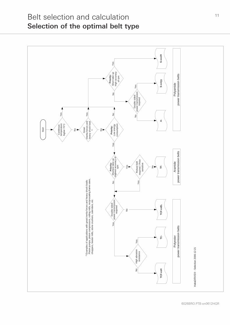
Selection of the optimal belt typeThe optimal belt type can be determined by reference to the Belt selection chart on the following page.
If the Habasit POWER-SeleCalc program is available, use the easy to handle Belt Selector in order to select the optimal belt type.
For further support please contact your Habasit partner.
Belt type
Initial elongation Belt width
11
6026BRO.PTB-en0612HQR
Belt selection and calculationSelection of the optimal belt type
Sta
rt
No
Gre
atin
terti
a fo
rces
and
heav
y sh
ock
load
1) No
Prio
rity:
Low
ene
rgy
cons
umpt
ion
Con
tinou
ste
mpe
ratu
rehi
gher
70°
C
Prio
rity:
Sho
rt ta
ke-u
pH
igh
accu
racy
of rp
m
S-xx
/yy
S-xx
x/H
1) E
xam
ples
of a
pplic
atio
ns w
ith g
reat
iner
tia fo
rces
and
hea
vy s
hock
load
s:P
isto
n pu
mps
, pis
ton
com
pres
sors
, rol
ling
mill
s, re
cipr
ocat
ing
fram
e sa
ws,
ch
oppe
rs, b
eate
r mill
s, s
tone
cru
sher
s, c
alen
ders
, etc
.
Hig
h ab
rasi
onre
sist
ance
Prio
rity:
Sho
rtest
take
-up
Hig
hest
acc
urac
y of
rpm
Yes
Rob
ust b
elt
requ
ired
/ Pric
ese
nsiti
ve
No
TF-
Dou
ble
side
dpo
wer
tran
smis
sion
requ
ired
A-
Pol
yam
ide
pow
er tr
ansm
issi
on b
elts
Dou
ble
side
dpo
wer
tran
smis
sion
requ
ired
Yes
No
Ara
mid
epo
wer
tran
smis
sion
bel
tsP
olye
ster
pow
er tr
ansm
issi
on b
elts
Yes
Yes No
No
Yes
Yes
No
Yes
seYo
N
Yes
No
TCF-
xxH
TC-
TCF-
xxEL
Hab
aDR
IVE
® -
Sel
ectio
n 20
06-1
2-21

12
6026BRO.PTB-en0612HQR
Belt selection and calculationCalculation by POWER-SeleCalc
The Habasit POWER-SeleCalc program can be ordered free of charge via our website www.habasit.com, by e-mail [email protected], or by contacting your Habasit partner.
The Habasit POWER-SeleCalc program enables the user to perform a belt selection in terms of machine and environmental influences, and to calculate the technical drive data such as belt width, initial elongation, static and dynamic shaft load, effective belt length, etc. of two pulley drives, drives with tension pulley, and tangential belt drives, in a quick and easy way.
Drive configurationinput / selection mask
Single stage drive / open drive (two pulley drive)
Selection / input mask Belt selector mask Result printout
Further input maskt Result screen
Selection / input mask
Tangential belt drive
Option: Printout ofProduct Data Sheets

13
6026BRO.PTB-en0612HQR
Technical belt dataBelt length
In belting technology, there are a few special expressions and technical data which need a brief explanation.
Belt lengthThe length of power transmission flat belts can be expressed in three ways:• Geometric belt length (lg)• Effective belt length (leff)• Shortened belt length (ls)
For common two pulley drives, the difference between geometric and effective belt length is negligible. However, in specific applications, e.g. short centre distance and/or relatively thick belts, limited take-up etc., greater calculation accuracy is necessary.
Please note that the theoretical considerations below are automatically taken into consideration when using the POWER-SeleCalc calculation program.
Exact formula for the calculation of the geometric belt length of a two pulley drive:
Geometric belt length (lg)The geometric belt length means the inner circumference of an un-tensioned belt drive on the assumption that the belt is infinitely thin. The belt thickness and the position of the neutral layer are not considered.
[mm]
c = center distance [mm]ds = diameter of small pulley [mm]dl = diameter of large pulley [mm] = arc of contact on small pulley [°]
g s ll s
l c d dd d= ⋅ ⎛
⎝⎜⎞⎠⎟
+ + +−( ) −( )⎡
⎣⎢
⎤
⎦⎥2
2 2180
180s in
β π β
β = 2 arc cos ( dl - ds ) = [°] 2c

14
6026BRO.PTB-en0612HQR
Technical belt dataBelt length
Exact formula for calculation of the effective belt length of a two pulley drive:
In machines with defined take-up displacement, where the belt is elongated to a fixed end position, usually the center distance for the tensioned belt (cε) is known.
[mm]
c = center distance [mm]ds = diameter of small pulley [mm]dl = diameter of large pulley [mm]s = position of the neutral layer measured from running side [mm] = arc of contact on small pulley [°]
eff s ll s
l c d d s d d= ⋅ ⎛⎝⎜
⎞⎠⎟
+ + + +−( ) −( )⎡
⎣⎢
⎤
⎦⎥2
2 24
180180
s inβ π β
cε = center distance of tensioned belt [mm]xε = take-up displacement [mm]
Formula for the calculation of the take-up displacement (xε):
[mm]
The effective length (fabrication length) of the un-tensioned belt has to be calculated accordingly:
eff s ll s
l c x d d s d d= −( ) ⋅ ⎛⎝⎜
⎞⎠⎟
+ + + +−( ) −( )⎡
⎣⎢
⎤2
2 24
180180ε ε
β π βs in
⎦⎦⎥
leff = effective length of the un-tensioned belt [mm]ε0 = initial elongation [%]
Effective belt length (leff)The effective belt length is the length of the neutral layer of an un-tensioned belt. It is identical with the fabrication length.
εε
xleff o= ⋅
⋅2 100

15
6026BRO.PTB-en0612HQR
Technical belt dataBelt length
[mm]
[mm]
lε = length of the tensioned belt [mm]
The basic formula for the calculation of the shortened belt length (ls), that is the fabrication length, is:
sg
ol
l s=
⋅ + ⋅( )⎡⎣ ⎤⎦+
100 2
100
π
ε
ε0 = initial elongation [%]
Usually the geometric belt length (lg), this means the inner circumference of the tensioned belt, is known. The position of the neutral layer (s) has therefore to be considered in the formula for the calculation of the shortened belt length:
Note: If the drive is equipped with a tensioning device, but the available take-up displacement is not sufficient to obtain the effectively calculated take-up displacement (xε), the belt may be partially shortened.
Shortened belt length (ls)In applications without any tensioning device at all, the belt must be fabricated shorter by the amount equal to the required initial elongation.
Is = 100 · Iε 100 + ε0

16
6026BRO.PTB-en0612HQR
Technical belt dataTensile force for 1% elongation (k1% value)
To achieve elongation a certain tensile force (F) is required. At the end of the elongation the tensile force immediately starts to decrease, first considerably, later moderately, until the force remains constant. The explanation for this is a microscopic displacement of molecular chains against each other. This viscoelastic phenomenon is called “relaxation”.
Habasit considers the relaxation of power transmission belts by measuring the k1% value after the relaxation phase or running-in time period.
This is why the value is called k1% after running-in:
The k1% value indicates the tensile force per unit of belt width that is required to elongate it by 1% [N/mm].
Tensile force for 1% elongation after running-in (k1%a.r.i.)The correlation of force and elongation of synthetic material is influenced by the elapsed time after stretching, temperature and humidity. While the influence of temperature and humidity is quite complex (and will not be further discussed here), the influence of time on force/elongation behavior after stretching synthetic material cannot be neglected.
In the following it is described what happens when a synthetic material, like a power transmission belt, is elongated:
k1% a.r.i. = tensile force for 1% elongation per unit of width after running-in [N/mm]
The k1% a.r.i. is the decisive value for calculating the required belt width and the resulting shaft load after belt relaxation.

17
6026BRO.PTB-en0612HQR
Technical belt dataShaft load – Nominal peripheral force
Shaft loadThe described relaxation phenomena directly influence the shaft load.
Nominal peripheral force The nominal peripheral force (F‘UN) indicates the force which can be transferred from the circumference of the drive pulley to the belt in Newton per unit of belt width [N/mm].
The F‘UN is the product of the k1% after running-in (k1%a.r.i.) and the admissible elongation (εadm) of the belt, considering the coefficient of friction (μ) between belt and steel pulley.
The admissible elongation is determined by extensive tests for each belt type.
Note: The nominal peripheral force indicates the effective strength of a power transmission flat belt.
If a power transmission belt is tensioned to the required initial elongation, the resulting shaft load will be at maximum (FWpeak) immediately after elongation.
Where the belt is tensioned to a constant elongation, the shaft load decreases over the course of time. While the shaft load reduction is relatively large at first (the main part of the belt relaxation takes place within the first 2–3 hours after tensioning), it gradually tapers off until the shaft load remains constant (FWa.r.i.).
The highest shaft load (FWpeak), appearing immediately after elongation, is about 40% to 50% higher than the shaft load after relaxation or after running-in (FWa.r.i.), depending on belt type and elongation conditions.
This fact must be considered when specifying shafts and bearings (see the chapter on “Design guidelines, bearings”), in the engineering of the drive frame, as well as during belt installation (see the chapter on “Belt installation”).
Habasit’s shaft load indications refer to the situation after relaxation, after running-in respectively.
We distinguish between the static shaft load (at standstill FWs) and the dynamic shaft load (in operaion FWd), where centrifugal forces are considered.
Note: Where the belt is tensioned by a constant force, mechanical force (hydraulic or pneumatic cylinder or spring) or by force of gravity, the shaft load remains constant, but the belt changes its length. This means it elongates after tensioning due to relaxation, until the length remains constant.

18
6026BRO.PTB-en0612HQR
Design guidelinesGeneral drive design
Flat belt drives transmit power by friction. This fact means that the belt needs to be pressed onto the periphery of the pulley with a certain force. This force creates a shaft load which has to be borne by the shafts and bearings. Finally, the installation has to take up all forces without appreciable distortion. This leads to the following conclusions:
a) Example of an appropriate, distortion-resistant bearing support
b) Example of an inappropriate design
1 Weak and non-distortion-resistant design of the bearing support
2 Bearings supported by rubber rings (mechanically weak and cause electrostatic charge)
• The installation must be grounded (electrically connected with the earth potential) in order to prevent an electrostatic charge. Exercise caution with synthetic-supported bearings or mobile installations on rubber wheels!
• The drive structure must be rigid and distortionresistant, i.e. machine frame, shaft bearings and motor mounting must be sized in accordance with the maximum developed tension forces and related shaft loads.
• All shaft and roller axes coming into contact with the belt must be perpendicular to the belt running axis.
19
6026BRO.PTB-en0612HQR
Design guidelinesFlat belt pulleys
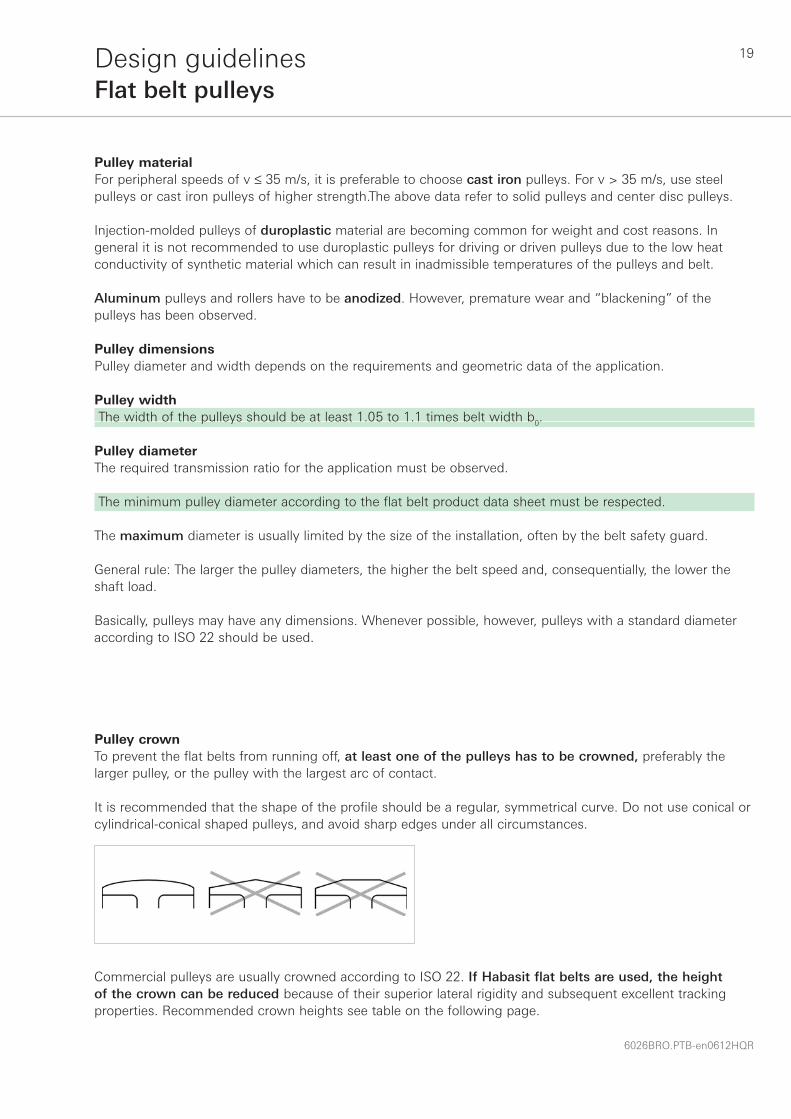
Pulley crownTo prevent the flat belts from running off, at least one of the pulleys has to be crowned, preferably the larger pulley, or the pulley with the largest arc of contact.
It is recommended that the shape of the profile should be a regular, symmetrical curve. Do not use conical or cylindrical-conical shaped pulleys, and avoid sharp edges under all circumstances.
Pulley materialFor peripheral speeds of v ≤ 35 m/s, it is preferable to choose cast iron pulleys. For v > 35 m/s, use steel pulleys or cast iron pulleys of higher strength.The above data refer to solid pulleys and center disc pulleys.
Injection-molded pulleys of duroplastic material are becoming common for weight and cost reasons. In general it is not recommended to use duroplastic pulleys for driving or driven pulleys due to the low heat conductivity of synthetic material which can result in inadmissible temperatures of the pulleys and belt.
Aluminum pulleys and rollers have to be anodized. However, premature wear and “blackening” of the pulleys has been observed.
Pulley dimensions Pulley diameter and width depends on the requirements and geometric data of the application.
Pulley width The width of the pulleys should be at least 1.05 to 1.1 times belt width b0.
Pulley diameterThe required transmission ratio for the application must be observed.
The minimum pulley diameter according to the flat belt product data sheet must be respected.
The maximum diameter is usually limited by the size of the installation, often by the belt safety guard.
General rule: The larger the pulley diameters, the higher the belt speed and, consequentially, the lower the shaft load.
Basically, pulleys may have any dimensions. Whenever possible, however, pulleys with a standard diameter according to ISO 22 should be used.
Commercial pulleys are usually crowned according to ISO 22. If Habasit flat belts are used, the height of the crown can be reduced because of their superior lateral rigidity and subsequent excellent tracking properties. Recommended crown heights see table on the following page.
20
6026BRO.PTB-en0612HQR
Design guidelinesFlat belt pulleys
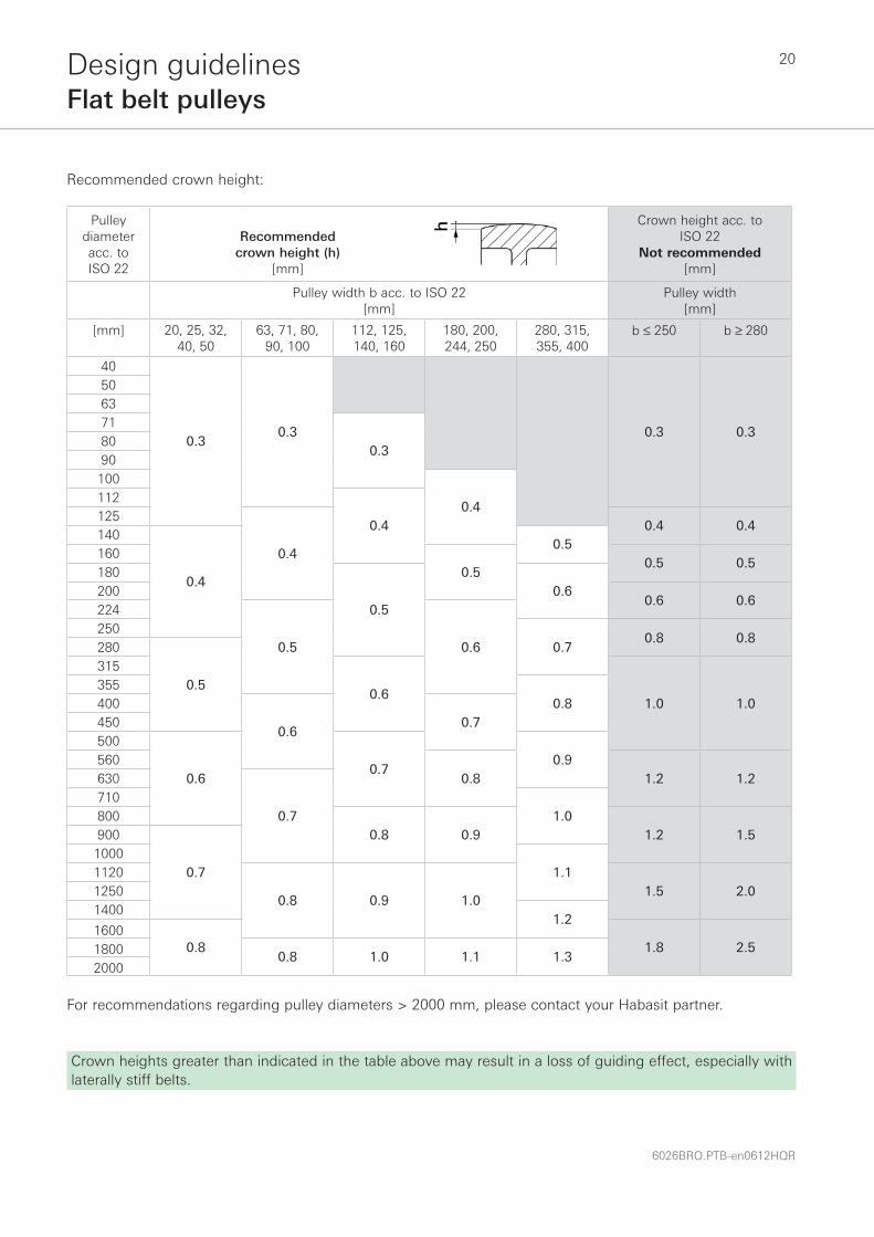
For recommendations regarding pulley diameters > 2000 mm, please contact your Habasit partner.
Pulley diameter acc. to ISO 22
Recommended crown height (h)
[mm]
Crown height acc. toISO 22
Not recommended [mm]
Pulley width b acc. to ISO 22[mm]
Pulley width [mm]
[mm] 20, 25, 32,40, 50
63, 71, 80,90, 100
112, 125,140, 160
180, 200,244, 250
280, 315,355, 400
b ≤ 250 b ≥ 280
40
0.30.3 0.3 0.3
506371
0.38090100
0.4112
0.4125
0.4
0.4 0.4140
0.4
0.5160
0.50.5 0.5
180
0.50.6200
0.6 0.6224
0.5 0.6250
0.70.8 0.8
280
0.5315
0.61.0 1.0
3550.8400
0.60.7450
500
0.60.7
0.95600.8 1.2 1.2630
0.7710
1.08000.8 0.9 1.2 1.5900
0.71000
1.11120
0.8 0.9 1.01.5 2.01250
14001.2
16000.8 1.8 2.51800 0.8 1.0 1.1 1.3
2000
Recommended crown height:
Crown heights greater than indicated in the table above may result in a loss of guiding effect, especially with laterally stiff belts.

21
6026BRO.PTB-en0612HQR
Design guidelinesFlat belt pulleys
Correlation of crown (h) and manufacturing radius (R)
[mm]
[mm]
The higher the arc of contact, the better the tracking effect of crowned pulleys.
hbtg
arcbR=
⎛⎝⎜
⎞⎠⎟
⎛
⎝
⎜⎜⎜⎜
⎞
⎠
⎟⎟⎟⎟
22
2
s in
Rh b
h= +
2 8
2
Pulley running surfaceClean and smooth running surfaces increase the efficiency and service life of power transmission belts.
The running surface of driving pulleys must not be too smooth, due to the risk of stick-slip and noise creation, and not too rough (no knurled surfaces!) as this can cause excessive belt wear and premature belt failure.
Habasit’s recommendation for the roughness of the running surface:
Ra = 6.3 to 3.2 μm (attainable by normal tooling on a lathe)
Ra = arithmetical mean deviation of the profile according to ISO 4287
For small pulley and roller diameters (approx. 200 mm) a smoother surface is possible, but not necessary, e.g. Ra = 1.6 μm (only attainable on a precision lathe with high accuracy).
Avoid smoother surface roughness than Ra = 3.2 μm on large and wide driving and driven pulleys due to the risk of stick-slip.
Pulley balance qualityFor peripheral speeds up to v = 30 m/s and diameter d = 355 mm, pulleys are usually balanced in one plane, quality grade G 1.6, according to ISO 1940 (VDI 2060).
For higher peripheral speeds of v > 30 m/s and diameter d > 355 mm, pulleys are best dynamically balanced in two planes.

22
6026BRO.PTB-en0612HQR
Design guidelinesFlat belt pulleys
Flanged pulleys
Avoid flanged pulleys and flanged rollers because there is a risk of belt damage if the belt runs onto the flanges
In exceptional cases, e.g. where long tangential belts have to be kept in the right position during instalation, flanged pressure rollers may be acceptable. However, the belt should not touch the flanges during normal operation.
The width of the running surface should be 20% to 30 % wider than the belt width (b0). The flange height (hr) should be about the same as the belt thickness and should be undercut to minimize the contact area with the belt.

23
6026BRO.PTB-en0612HQR
Design guidelinesBearings
Bearing selection and specificationSelection and specification of bearings according to the manufacturers’ guidelines.
Bearing loadIt is a prerequisite for the determination of the bearing load to know the shaft load created by the tensioned belt (see the chapter on “Technical belt data, Shaft load”).
When using the POWER-SeleCalc calculation program, both the static shaft load (FWs) and the dynamic shaft load (FWd), are determined while calculating the belt.
Please consider when specifying the bearings that the highest shaft load (FWpeak), appearing for a short time immediately after elongation, is about 40 % to 50 % higher than the indicated shaft load FWs or FWd.
Note: In rare cases, e.g. if a very strong belt is unusually fast elongated, the shaft load appearing for a short time immediately after the first elongation can be up to 100% higher than the indicated shaft load in the POWER-SeleCalc calculation program.
If the basis for the calculation of the bearing load, the shaft load (FW), is known, the actual bearing load can be calculated as follows:
• Two-side bearing arrangement
[N]
[N]
It goes without saying that the resulting bearing load must not exceed the admissible bearing load indicated in the bearing data sheet.
Load on bearing A Fc cc
W= ⋅ −2 1
2
Load on bearing B Fcc
W= ⋅ 1
2
• One-side bearing arrangement
[N]
[N]Load on bearing B Fcc
W= ⋅ 1
2
Load on bearing A Fc cc
W= ⋅ −1 2
2
If the calculated maximal bearing load that appears is close to the limit or exceeds the admissible load of the bearings used, the following measures can be taken:
• If possible increase pulley diameters in order to reduce the shaft load• Choose a belt tension system using mechanical force (hydraulic or pneumatic cylinder or spring) or force of
gravity (constant shaft load). • Tension the belt in two steps when installing (see the chapter on “Belt installation, two step tensioning” on
page 50).
Note: Contrary to the wide-spread opinion, the shaft load and the resulting bearing load of power transmission flat belts are not higher, but about the same as in other non-positive driving elements such as V-belts and poly-V-belts, provided that they are installed properly.

24
6026BRO.PTB-en0612HQR
Design guidelinesTensioning device
Correct and sufficient initial elongation is a pre-requisite for trouble-free operation of power transmission flat belts. The calculated initial elongation (ε0) must be observed!
One has to distinguish between drive systems with variable centre distance, systems with defined take-up, systems with tensioning pulley, and systems with no tensioning device.
Systems with variable centre distanceThe most common system for two pulley drives. Usually the motor is mounted on an adjustable base. The belt is tensioned by moving the base. After tensioning, the base is fixed with screws.
Sufficient tensioning length in the direction of x must be provided corresponding to installation and belt length tolerance due to the influences of temperature and humidity on the belt length (namely the polyamide traction layer) etc. Further-more, the shaft has to be adjusted square to the belt running axis by adjusting the α angle.
Recommended take-up of the tensioning device:xr ≅ 3 · xε
Position of the pulley with un-tensioned belt Position of the pulley after tensioning to initial
elongation ε0 xε Effective required take-up displacement [mm]xr Recommended take-up of the tensioning
device [mm]
Systems with defined take-up Due to the well-defined take-up displacement (the belt is elongated to a fixed end position), improper adjustment of the required initial elongation during installation can be avoided.
leff = effective length (fabrication length) of the un-tensioned belt [mm]
lε = length of tensioned belt [mm] cε = center distance of tensioned belt [mm]xε = take-up displacement [mm]
Machines with defined take-up displacement appear to be an intelligent and user-friendly solution. However, the system has some drawbacks:
25
6026BRO.PTB-en0612HQR
Design guidelinesTensioning device
1. The effective belt length (fabrication length, leff) must be produced with a high level of accuracy. Small differences in length may cause considerable deviations in belt tension. This is especially true with a short belt length and/or belts with a high modulus of elasticity (high k1% value).
Observing the exact belt fabrication length is highly important with this system! Recommended fabrication length tolerance: 0/- yy mm.
Deviations in belt length cannot be compensated for on such a machine design. Re-tensioning is impossible. Problems including slip and premature belt wear result if the belt is too long.
2. Influences on the belt dimension due to temperature or humidity changes (polyamide belts) cannot be compensated for and may lead to an increase or decrease in the shaft load.
3. Tensioning can be done by a hand-driven spindle, which is quite a slow process that allows the belt to relax. Other methods, such as a knee-lever or pneumatic or hydraulic cylinder, tension the belt very fast, causing high belt stress and high shaft load before the belt relaxes, leading to excessive bearing and shaft load.
Abrupt tensioning, e.g. provided by hydraulic or pneumatic cylinders, may damage aramide belts (TF -range).
4 This kind of tensioning device is often designed for one particular belt type. Changing later to another belt type can lead to problems.
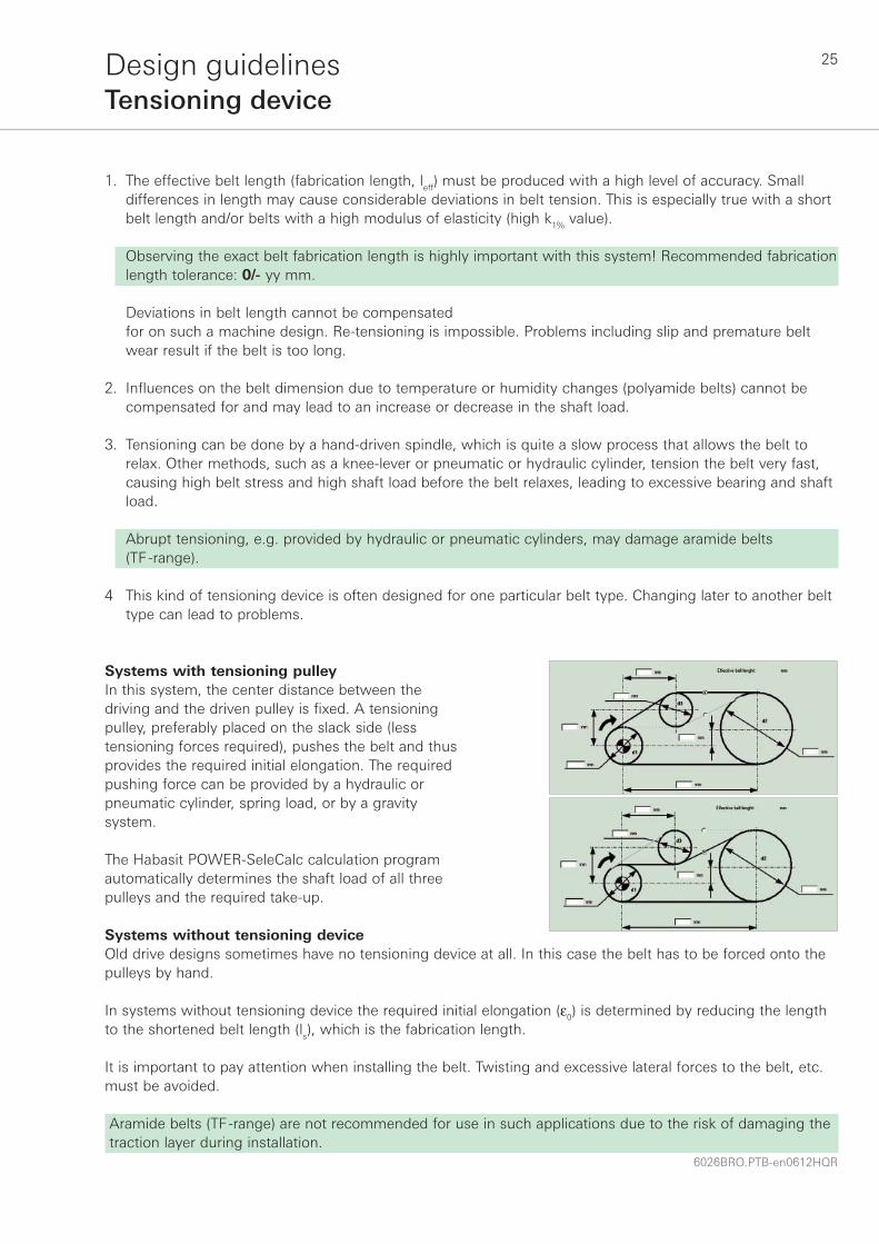
Systems with tensioning pulleyIn this system, the center distance between the driving and the driven pulley is fixed. A tensioning pulley, preferably placed on the slack side (less tensioning forces required), pushes the belt and thus provides the required initial elongation. The required pushing force can be provided by a hydraulic or pneumatic cylinder, spring load, or by a gravity system.
The Habasit POWER-SeleCalc calculation program automatically determines the shaft load of all three pulleys and the required take-up.
Systems without tensioning device Old drive designs sometimes have no tensioning device at all. In this case the belt has to be forced onto the pulleys by hand.
In systems without tensioning device the required initial elongation (ε0) is determined by reducing the length to the shortened belt length (ls), which is the fabrication length.
It is important to pay attention when installing the belt. Twisting and excessive lateral forces to the belt, etc. must be avoided.
Aramide belts (TF-range) are not recommended for use in such applications due to the risk of damaging the traction layer during installation.

26
6026BRO.PTB-en0612HQR
Special fl at belt drivesTangential belt drive
OverviewIn addition to the classical two pulley drive, there are many different drive applications where the flat power transmission belt is the ideal solution.
The following drive systems are presented in this chapter:• Tangential belt drive• Spindle tape drive• Live roller drive• Multi pulley drive (power branching)• Mule drive• Half-cross drive
Introduction to the tangential belt driveThe tangential belt drive is mainly used in the textile industry for driving spindles on ring spinning, open-end spinning, twisting and texturizing machines.
In principle, this is a tangential drive where the power is not transmitted to a single driven pulley but to an array of spindles or rotors. The spindles (rotors) are arranged in a linear manner with the belt pressed against them by pressure rollers to drive them tangentially.
This is why it is referred to as a “tangential belt drive”.
Tangential belt drives may have various arrangments, depending on the machine manufacturer, type and size of machines, etc. The most important systems are described in the following, without claim to completeness. The advantages and weaknesses described are general statements, which can be compensated for by special machine designs or special belt types, depending on the situation.

27
6026BRO.PTB-en0612HQR
Special fl at belt drivesTangential belt drive
Single belt / single drive system The tangential belt is driven on one end of the machine by a drive pulley and on the other end diverted by one or two rollers to return to the drive. The belt is normally driven on its inner side; on the outer side it drives hundreds of spindles or rotors.
Ring spinning Open-end spinning
1) Can be compensated by using TF- belts with aramide traction layers
Advantages of the system Weaknesses of the system
• Simple drive principle
• Large pulleys, few fl ections, no counter fl ection long belt service life
• Easy belt installation
• Strong belts required, thus high shaft and bearing load heavy machine design long take-up displacement 1)
• Signifi cant deviation of spindle rpm from fi rst to last spindle 1)
• Demanding belt tracking
• Effi ciency not optimal
• If belt fails all spindles (rotors) are out of production

28
6026BRO.PTB-en0612HQR
Special fl at belt drivesTangential belt drive
Single belt / dual drive systemThe tangential belt is driven by two motors placed at both ends of the machine. This reduces the power to be transmitted per motor and belt to 50 % compared with the “one-belt-one-drive” system.
1) Can be compensated by using TF- belts with aramide traction layers
Advantages of the system Weaknesses of the system
• Lower strength belts required compared with the single belt / single drive system, thus smaller shaft and bearing load lighter machine design
• Automatic speed control and adjustment of variable speed motors is less demanding compared with “multi drive” systems
• Large pulleys, few fl ections, no counter fl exion long belt service life
• Easy belt installation
• Deviation of spindle rpm from fi rst to last spindle conderable 1)
• Demanding belt tracking
• Greater effi ciency compared with the “single belt /single drive”, but still not optimal
• If belt fails, all spindles (rotors) are out of production

29
6026BRO.PTB-en0612HQR
Special fl at belt drivesTangential belt drive
Single belt/multi drive system With the multi motor drive, the tangential belt is driven by several motors arranged in regular intervals around the machine. As a consequence, lower strength tangential belts can be used. Machines with such a group drive have been produced to 60 meters in length, containing as many as 1500 spindles.
The number of revolutions of the individual motors must be perfectly synchronized and the diameter of the driving pulleys have to be in a narrow tolerance, otherwise the belt assumes the stresses of equalizing the speed, resulting in premature belt wear and reduced belt service life.
Advantages of the system Weaknesses of the system
• Lower strength belts required compared with the single belt / single drive system, thus smaller shaft and bearing load lighter machine design
• High effi ciency, low energy consumption
• Minimal difference in spindle rpm
• Automatic speed control and adjustment of variable speed motors is technically demanding expensive sensitive
• Premature belt wear, reduced service life and irregular yarn quality result if motors are not perfectly synchronized
• If belt fails, all spindles (rotors) are out of production
• Reduced service life due too small pulleys, a high number of reverse bending cycles and because only one side of the belt is used

30
6026BRO.PTB-en0612HQR
Special fl at belt drivesTangential belt drive
Dual belt drive systemTwo separately-driven tangential belts, one located on each side of the machine, each drives half of all the spindles, thus reducing the power to be transmitted per belt to 50%. This permits the use of lower strength belts and lower belt tension.
1) Can be reduced by using TF- belts with aramide traction layers
Advantages of the system Weaknesses of the system
• Lower strength belts required compared with the single belt/single drive system, thus smaller shaft and bearing load lighter machine design
• Relatively large pulleys, few fl ections and counter fl exions long belt service life
• If one belt fails, production can still run at 50% until repair is made
• Different initial elongation and running conditions for the two belts
• Difference in spindle rpm between left and right side (due to creep of the main drive) 1)
• Demanding belt tracking
• Demanding belt specifi cation
• Additional time required to replace all belts

31
6026BRO.PTB-en0612HQR
Special fl at belt drivesTangential belt drive
Section (segmented) drive systemWith the section drive (also called segmented or group drive) a single motor drives a central shaft, which is oriented along the length of the machine. Driving pulleys are fixed on the shaft and drive multiple tangential belts. Each tangential belt drives a small group of spindles, e.g. 24 spindles on each side.
Advantages of the system Weaknesses of the system
• Lower strength belts required
• Small difference in spindle rpm between left and right side of the machine
• High effi ciency, low energy consumption
• Time-saving belt installation of endless belts
• If one belt fails, only limited loss to production until repair is made
• Extensive drive system
• Small pulley diameters, high numbers of reverse bending cycles and belt twists reducing belt service life
• Accurate belt length required due to defi ned take-up

32
6026BRO.PTB-en0612HQR
Special fl at belt drivesTangential belt drive
Technical requirements on tangential beltsThe demands on tangential belts are many and may have different priority, depending on the type of application, machine type, belt speed, operating conditions, maintenance capabilities, etc.
• Energy savingModern, fl exible belts with a high modulus of elasticity, such as polyester fabric (TC-range) and aramide fabric (TF-range), can produce a high degree of effi ciency and as a consequence, realize considerable savings in energy costs.
• Long service life, low down-timeThis highly stressed machine element can still deliver a long service life provided that the belt is selected, installed and maintained according to these guidelines.
• Easy, fast and reliable joining methodIf belts have to be joined on the machine, an easy joining method – producing a uniform, reliable splice – is important in order to optimize up-time. The joint (splice) must not lead to belt vibrations.
• Suitable and constant force/elongation-ratioAn optimal force/elongation-ratio (E-modulus, k1%-value), which remains constant throughout the belt’s service life ensures highly consistent and superior yarn quality, low belt maintenance, and long belt life.
• High and constant coeffi cient of frictionTangential belts must transmit the necessary peripheral force without slipping under all operating conditions. This requires a high coeffi cient of friction of the cover that will remain constant during the entire service life. The normal infl uence of humidity, batching oil, fi bers and other debris must not lead to slipping problems.
• Vibration-free running
For reasons of noise control and yarn quality, as well as with regard to achieving a high service life of the tangential belt, spindle bearings and other machine parts, the belt should provide quiet, vibration-free operation, particularly at the highest running speed. Uniform belt thickness and a homogeneous joining area are, therefore, important belt features.
• Minimum run-up timeAfter splicing of the thread, the spindle (rotor) brake is released and the spindle (rotor) is again accelerated to its normal operating speed. The run-up time has to be within a time frame of few seconds. This is attainable with a high E-modulus (k1%-value) and a high and consistent friction tangential belt.
• Perfect tracking, no maintenanceTo ensure optimum, maintenance-free belt performance and service life, tangential belts must not run off the pulleys and/or whirls during operation. Therefore, proper component alignment and belt tension must be ensured
• Short take-upThe considerable length of today’s textile machines should not be additionally increased by the need for a long take-up mechanism. A high E-modulus (k1%-value) of the tangential belt is, therefore, desirable.
• High accuracy of spindle revolutionsConsistent yarn quality is a function of spindle speed accuracy. A high E-modulus (k1%-value) produces less creep in the belt drive, which means a smaller speed difference between the fi rst and the last spindle, thereby improving yarn quality.
• Resistant to chemicals Belts must be resistant to typical lubricating chemicals (oil, fat, batching oil, avivage) to ensure consistent performance and optimum service.

33
6026BRO.PTB-en0612HQR
Special fl at belt drivesTangential belt drive
Recommended product rangeFor new machines with a high focus on low energy consumption: • TC-range
For highly demanding applications regarding shortest take-up, lowest energy consumption and highest accuracy of rpm:• TF -range
For older machines, flanged pulleys and very warm environments:• S-range
Belt calculation If the machine data is known (complete the questionnaire in the appendix), the required belt data can be calculated exactly by means of the POWER-SeleCalc program.
Note: The calculation of tangential belts is quite demanding, even with the POWER-SeleCalc program, and specific know-how is required. In case of doubt we recommend to contact your Habasit partner to perform or check your calculation.
Design recommendationsThe general statements in the chapter “Design guidelines”, starting on page 18, should be observed. Use crowned pulleys and rollers, and avoid flanged pulleys! It is always good to contact your Habasit partner for detailed support.
Installation and maintenanceThe general statements in these chapters (pages 47–53) should be observed.

34
6026BRO.PTB-en0612HQR
Special fl at belt drivesSpindle tape drive
IntroductionThe spindle drive is an alternative to the tangential belt. It is used in the textile industry for driving spindles on ring spinning and twisting machines. The spindle tape touches the whirls with an arc of contact of at least 90°.
Technical requirements on spindle tapesHigh quality spindle tapes must have specifi c properties such as:
• Energy savingModern, fl exible spindle tapes have a high degree of effi ciency. As a consequence, considerable energy cost savings can be realized.
• Easy, fast and reliable joining methodConsidering that hundreds of spindle tapes per machine have to be made endless, an easy (preferably adhesive-free) and reliable joining method is required.
• Highest spindle revolution (rpm)Spindle tapes for modern spinning machines must be designed for spindle speeds up to 20,000 rpm and higher.
• High accuracy of spindle revolutionA high modulus of elasticity produces less creep, which means that a smaller speed difference results between the fi rst and the last spindle, which in turn improves yarn quality.
• No fi ber / fl uff accumulationSpindle tapes must have sharp, clean, smooth edges, and must not accumulate static charges, so that no fi bers or debris is attracted and sticks to the tape surface, thus reducing friction.
• Long service life, low down-timeA long service life of this highly stressed machine element can be expected.
• Low speed loss of running spindles when neighbor spindles are stopped When a spindle is braked, it is expected that the adjacent spindles continue to run with negligible loss of speed (objective: uniform yarn quality).
• High temperature resistanceAt thread breakage, the spindle will be stopped by a mechanical break. The spindle tape, however, continues to run on the stopped whirl. The resulting temperatures of up to 60 °C must be overcome by the spindle tape without any damage.
• Minimum run-up time After automatic or manual splicing of the thread, the spindle brake is released and the spindle is again accelerated to its nominal number of revolutions. The run-up time must be within a time frame of a few seconds.

35
6026BRO.PTB-en0612HQR
Special fl at belt drivesSpindle tape drive
Available spindle tapes products W-8 The best energy-saving spindle tape in the world (adhesive-free joint)
W-16 Stronger version of W-8 (adhesive-free joint)
TS-5 The most popular spindle tape in the world (polyamide type); excellent heat resistance, very robust, long lasting
TS-55 Stronger alternative to TS-5
TS-10 Suitable when lubricants are present; not applicable for applications requiring the braking (stopping) of spindles.
HS-5/HS-55 Economical alternatives to TS-5 and TS-55 (polyamide type)
Belt selection and calculation aidsBelt selection is according to the requirements of the machine and customer preferences. Contact your Habasit partner to provide calculations for special requests.
Design recommendationsThe general statements in the chapter “Design guidelines”, starting on page 18, should be observed.
Installation and maintenanceThe general statements in these chapters and the following additional statement must be observed (pages 47–53).
All spindle tapes have two different friction covers. In order to ensure trouble-free, efficient performance of the tapes, it is essential to follow the following rules during installation:• High coefficient of friction on driving pulley• Low coefficient of friction on spindle whirl

36
6026BRO.PTB-en0612HQR
Special fl at belt drivesSpindle tape drive
Correlation of material color and coefficent of friction:
Spindle tape type High coefficient of frictionon driving pulley side
Low coefficient of frictionon whirl side
W-8, W-16 Black GreenTS-5, TS-55, TS-10 Green YellowHS-5, HS-55 Green Beige
Correct installation of W-8 and W-16:
Correct installation of TS-5 (HS-5), TS-55 (HS-55) and TS-10:

37
6026BRO.PTB-en0612HQR
Special fl at belt drivesLive roller conveyor drive
IntroductionLive roller conveyors (LRC) play an important role in modern materials handling engineering. Piece goods in a broad range of sizes can be carried over shorter or longer distances, in a straight line as well as through curves, with relatively low energy consumption. Transport usually takes place horizontally, although slight inclines are also possible.
The goods are transported by a roller conveyor. The rollers are driven by a strong and therefore relatively narrow flat belt. The power transmission between belt and rollers is accomplished by the use of pressure rollers. The transported goods move in the opposite direction to that of the drive belt.
1 Transported piece good 2 Driving pulley3 Carrying rollers4 Pressure rollers5 Driving belt6 Return pulley

38
6026BRO.PTB-en0612HQR
Special fl at belt drivesLive roller conveyor drive
Continuous running systemIn a continuous running system, the carrying rollers are driven continually. There is no accumulation of goods and thus no stopping of the rollers. Pressure rollers can be fitted therefore in a fixed position. Flat belts with friction covers (NBR) on both sides are used as driving element. Rollers in continuous running systems may also be driven by Polycord round belts − a solution that is particularly suited for curves.
Accumulation systemWhere products need to be accumulated on the LRC for subsequent controlled retrieval, a distinction is made between systems where the continuous running belt remains in contact with the rollers while they are blocked by the accumulated goods (low pressure accumulation), and systems where the belt is separated from the rollers (zero pressure accumulation).
Zero pressureaccumulation
Low pressureaccumulation
AccumulationContinuousrunning
Live roller conveyor systems
Flat belt driven LRC are particularly well suited for goods accumulation and subsequent singulation processes. For the selection of the flat belt it is important to know exactly which LRC system will be used.
39
6026BRO.PTB-en0612HQR
Special fl at belt drivesLive roller conveyor drive
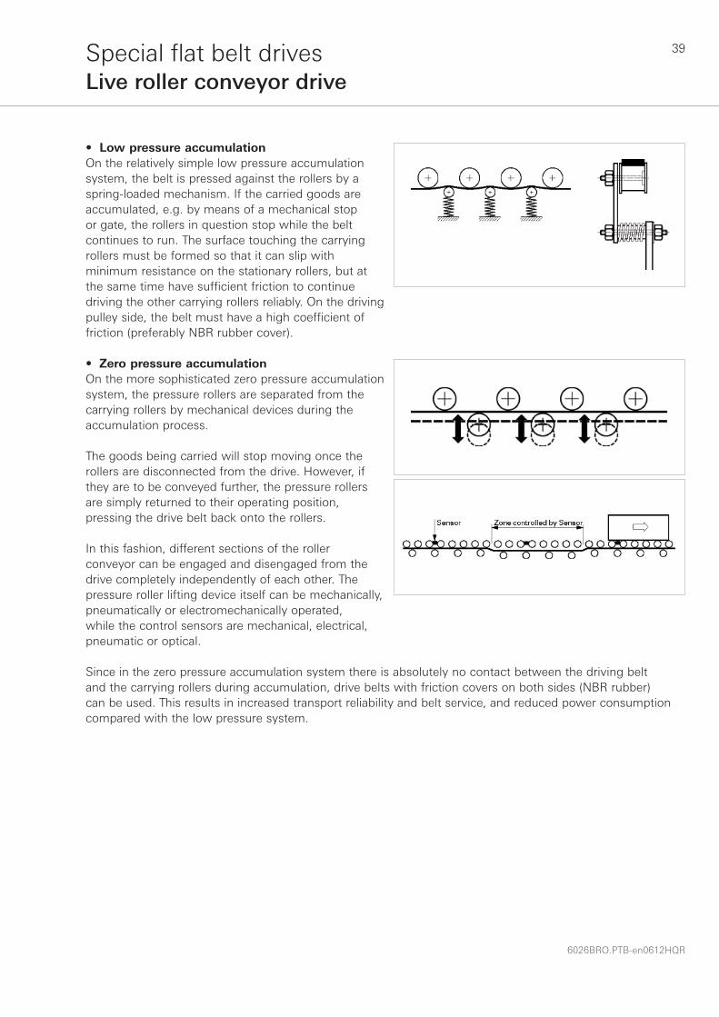
• Low pressure accumulationOn the relatively simple low pressure accumulation system, the belt is pressed against the rollers by a spring-loaded mechanism. If the carried goods are accumulated, e.g. by means of a mechanical stop or gate, the rollers in question stop while the belt continues to run. The surface touching the carrying rollers must be formed so that it can slip with minimum resistance on the stationary rollers, but at the same time have sufficient friction to continue driving the other carrying rollers reliably. On the driving pulley side, the belt must have a high coefficient of friction (preferably NBR rubber cover).
• Zero pressure accumulationOn the more sophisticated zero pressure accumulation system, the pressure rollers are separated from the carrying rollers by mechanical devices during the accumulation process.
The goods being carried will stop moving once the rollers are disconnected from the drive. However, if they are to be conveyed further, the pressure rollers are simply returned to their operating position, pressing the drive belt back onto the rollers.
In this fashion, different sections of the roller conveyor can be engaged and disengaged from the drive completely independently of each other. The pressure roller lifting device itself can be mechanically, pneumatically or electromechanically operated, while the control sensors are mechanical, electrical, pneumatic or optical.
Since in the zero pressure accumulation system there is absolutely no contact between the driving belt and the carrying rollers during accumulation, drive belts with friction covers on both sides (NBR rubber) can be used. This results in increased transport reliability and belt service, and reduced power consumption compared with the low pressure system.

40
6026BRO.PTB-en0612HQR
Special fl at belt drivesLive roller conveyor drive
Technical requirements on live roller driving beltsDue to their relatively low belt speeds, the demands regarding running properties are relatively low. However, the belts still have to be robust, because they are often exposed to strong mechanical loads, e.g. due to start-stop operation, relative movement on stationary rollers, lateral contact on flanged pulleys, etc.
Belt selectionHabasit can provide the optimal belt type for every LRC system:
* NBR rubber by preference
LRC system Required belt design Belt recommendations
Continuous running system
Zero pressure accumulation
Carrying roller side:Adhesive surface *
Driving pulley side:Adhesive surface *
Power transmission belts:TC-rangeTCF -20H, TCF-50HTF-rangeS-range
Other possibilities (examples):MAM-5ECM-18/30F
Low pressure accumulation Carrying roller side:Non-adhesive surface
Driving pulley side: Adhesive surface *
Power transmission belts:TF-75T, TF -75TE
Other possibilities (examples):MAM-5PFAB-xxE EMB-12EMCH, EMB-20EMCHENU-20EXBDEMB-27EHBT
Further belt types are available for special requirements, such as use in cold environments, etc. As an alternative to flat belts, LRC are often equipped with round belts (Polycord®, Habicord). For further information please contact your Habasit partner.
Calculation aids For driving belt calculations for special requests please contact your Habasit partner.
Design recommendationsThe general statements in the chapter on “Design guidelines” should be observed.
Belt installation and maintenanceThe general statements in these chapters should be observed.
Alternative: HabasitLINK® modular belt conveyorAs an alternative to the belt driven live roller conveyor system, the HabasitLINK® modular belt conveyor can be considered for new installations. For further information see www.habasit.com or contact your Habasit partner.

41
6026BRO.PTB-en0612HQR
Special fl at belt drivesMulti pulley drive (power branching)
IntroductionOne drive pulley powers several pulleys via one belt, whereby at least two driven pulleys transmit power to energy-consuming machine parts. Power branching often includes the reverse rotation of driven pulleys (double side power transmission).
1 Driving pulley2 Driven pulleys, change of rotating direction3 Driven pulleys, same rotating direction as driving pulley
Belt selection Selection of the optimal belt type has to be made according to the requirements of the application, customer preferences and cost considerations.
Single sided power transmission: • A and TCF-xxEL-range
Also possible TC-, TF- and S-range
Double sided power transmission: • TC-, TF- and S-range
See also Belt Selection Chart on page 11 or contact your Habasit partner.
Belt calculationPlease note that multi pulley drives with power branching cannot be calculated by the POWER-SeleCalc program.
We recommend that you send the drive data to your Habasit partner for exact calculation.
Design recommendationsThe general statements in the chapter “Design guidelines” should be observed.
Belt installation and maintenanceThe general statements in these chapters should be observed.
The largest circumference circles of all crowned pulleys must be precisely aligned in the same plane to ensure a proper belt tracking response.

42
6026BRO.PTB-en0612HQR
Special fl at belt drivesAngular drive (mule drive)
IntroductionIn a angular drive the driving and the driven pulley can be arranged in rectangular position.
d1 = diameter of driving pulleyd2 = diameter of driven pulleydg = diameter of guiding rollersb = pulley widthb0 = belt widthc1 = center distancec2 = center distance
Recommended product range• TC- or TCF-xxEL range
Also possible A- and S-range
Non-recommended product rangeDo not use TF-belts (aramide is sensitive regarding twisting and buckling).
Belt calculationIf the machine data are known, the required belt data can be calculated by the POWER-SeleCalc program.
Design recommendationsThe general statements in the chapter “Design guidelines”, starting on page 18, should be observed. The fol-lowing additional recommendations for angular drives are based on experience:• The greater the center distance (c1, c2), the better.
It should be at least 10 times the belt width.• The width of the driving and driven pulley must be 1.5 to 2 times the belt width• Crown both the driving and the driven pulley• The guiding roller width must be at least 2 times the belt width• The guiding rollers must be cylindrically
Belt installation and maintenanceThe general statements in these chapters should be observed (pages 47–53).

43
6026BRO.PTB-en0612HQR
Special fl at belt drivesHalf-cross drive
d1 = diameter of driving pulleyd2 = diameter of driven pulleyc = center distance
IntroductionThe half-cross drive serves to transmit power between two shafts, the axes of which cross at an angle of 1° to 90°.
PreconditionsThe belt must run parallel onto the pulleys (perpendicular to the axis). Running in reverse direction is not possible.
Recommended product range• TC-range
Also possible S-range
Not recommended product rangeDo not use TF-belts (Aramide is sensitive regarding twisting and buckling).
Belt calculationIf the machine data are known, the required belt data can be calculated by the POWER-SeleCalc program.
Note: One belt edge experiences, depending on the center distance c, additional tensile stress (σ+, see fi gure) through distortion. Belts in half-cross drives must therefore be stressed only up to 80% of their performance. This can be taken into consideration by making the center distance as big as possible (see recommendations on page 44) and increasing the indicated belt width by approx. 20%.

44
6026BRO.PTB-en0612HQR
Special fl at belt drivesHalf-cross drive
Design recommendationsThe general statements in the chapter “Design guidelines” should be observed. The following additional recommendations for half-cross drives are based on experience:• The ratio of the small to the large pulley must not exceed 0.4• It is an advantage to make the distance between the axes
as big as possible and to choose a narrow belt• The greater the center distance (c) the better. It should be
at least 10 times the belt width• The pulley width must be at least twice the belt width• Both pulleys must be designed cylindrically• At least one pulley has to be designed in a way that
it can be pivoted in plane parallel to its own axis and perpendicular to the other pulley axis.
• The pulleys must be displaced by the amounts: y ≅ 0.5 · b0
z ≅ (0.1−0.2) · b0
• The displacements must be made in such a way that the belt at the driving end is less laterally buckled than at the slack end
Belt installation and maintenanceThe general statements in these chapters should be observed (pages 47–53).

45
6026BRO.PTB-en0612HQR
FabricationFlexproof joining system
Advantages Limitations
• Longitudinal fl exibility, no stiffening of the joint• No stiffening over the joint, low vibration running• Good appearance; quality is easily assessed by
visual inspections
• Temperature resistance, not for high operating temperatures (limit 60° to 80 °C)
Flexproof joining system (finger joint)Flexproof is a fusion joint used without the addition of adhesive. It ensures simple joining and quick installation.
Process dataSee ”Joining data sheets“ on www.habasit.com
Recommended joining tools (examples)
Preparing devices Pressing devices
AF-605 PF-61
AF-100/US PM-309

46
6026BRO.PTB-en0612HQR
FabricationThermofi x joining system
Thermofix joining systemThermofix is an adhesive bonded joint. A variety of procedures and adhesives are employed, which are dependent upon belt type.
Advantages Limitations
• Admissible operating temperature up to 100 °C • Belt is slightly stiffer at the joint• Quality of joint skills depends on fabricator
Process dataSee ”Joining data sheets“ on www.habasit.com
Recommended joining tools (examples)
Preparing devices Pressing devices
AT-305 PT-100
PM-309

47
6026BRO.PTB-en0612HQR
Belt installation – Safety regulations
Belt installationIn order to guarantee problem-free running and to benefit from the features of the flat belt drive, the power transmission belts must be selected and installed correctly. Safety regulations and installation hints must be followed thoroughly.
Safety regulationsIf touched, running belts can catch parts of the body and objects e.g. clothing, tools, etc. and cause serious bodily injury and machine damage.
Switch off the machine using the main switch and ensure that it cannot be switched on again before installation, adjustment or maintenance work is carried out.
Power transmission belts should only be installed on the equipment for which they have been selected and calculated according to Habasit documentation.
Only qualified personnel who are authorized to perform the required installation and equipment maintenance may perform this work. They must possess the requisite knowledge and skills to effectively perform such work in accordance with the necessary provisions and accident-prevention regulations.

48
6026BRO.PTB-en0612HQR
Belt installationFirst-time installation
The following recommendations apply to the first installation of endless belts.
3. The running surfaces of the pulleys must be clean and free from grease, soil and dust.4. Before installing, trace small measuring marks at a distance of e.g. 1000 mm (recommendation) on the
un-tensioned belt. Use a ball-point pen and mark as accurately as possible! Do not place the measuring distance over the joining area.
Proceed as follows:1. Make sure that the tensioning device is in the
innermost position.2. Check that the shafts are parallel and the pulleys
aligned perpendicular to the belt running axis.
For short belts or if the control distance on the machine is shorter, choose a shorter measuring mark distance, e.g. 500 mm.
The longer the distance between the measuring marks, the higher the tensioning accuracy.
5. Install the belt carefully. Lay it first on the small pulley, then on the large pulley. Do not force the belt over the pulley edges. Do not use unsuitable tools such as screwdrivers, hammers, etc.
Special care has to be taken when installing belts with an aramide traction layer (TF-belts). These belts are sensitive to twisting and buckling.
6. Tension flat belt by enlarging the center distance until the distance between the measuring marks has increased by the value of the required (calculated) initial elongation (ε0)

49
6026BRO.PTB-en0612HQR
Belt installationFirst-time installation
Never tension a power transmission belt by guesswork; always observe the calculated initial elongation ε0!
If the correct initial elongation is not known, calculate it with the POWER-SeleCalc program or call Habasit application support.
In exceptional cases, if no indication is available at all, observe the approximate values:
7. Rotate the belt once or twice by hand. The flat belt must not drift or run off even when the direction of rotation is changed.
8. Check the distance of the measuring marks again. If necessary, tension the belt to the required initial elongation.
9. Fix the screws of the tensioning device.
10. Secure the original protective casing before starting the motor.
11. Make sure that the belt data (type, dimensions, quoted initial elongation, date of installation and maintenance instructions are stored near the machine, e.g. in a self-adhesive envelope stuck on the machine).
Installation of aramide beltsPower transmission belts with an aramide traction layer (TF -range) must be installed with special care.
Do not twist belts with an aramide traction layer and do not tension the belts with sudden or excessive force!
The high modulus of elasticity of aramide fi bres in the TF-belts leads to two special features:• The required take-up displacement is extremely short• Even a small increase in the initial elongation may lead to a considerable increase in the tensile force and
shaft load. Extensive shaft defl ection or early breakdown of bearings may be the result.
Example: Required initial elongation ε0 = 2.0% Measuring mark distance of un-tensioned belt: 1000 mmMeasuring mark distance of tensioned belt: 1020 mm
If the initial measuring mark distance of an un-tensioned belt is not 1000 mm as recommended, adapt the tensioning accordingly. For examples see the table below:
Initial measuring mark distance (un-tensioned belt) [mm]
Measuring mark distance of tensioned belt [mm]
Calculated initial elongation ε0 [%]0.5 1.0 1.5 2.0 2.5
200 201 202 203 204 205500 502.5 505 507.5 510 512.5750 753.8 757.5 761.3 765 768.8
1000 (recommended) 1005 1010 1015 1020 10251500 1507.5 1515 1522.5 1530 1537.52000 2010 2020 2030 2040 2050
Initial tension [%]
Traction layer Belt range min. Average range
Polyamide (PA) S, A 0.5 1.5 – 2.5
Polyerster (PET) TC, TCF 0.3 1.0 – 2.0
Aramide TF 0.2 0.5 – 0.8

50
6026BRO.PTB-en0612HQR
Belt installationInstallation of strong belts and re-installation
Installation of strong belts (two-step tensioning) In applications where a relatively strong belt is being installed on an inappropriately weak drive design we recommend tensioning in two steps:
1st step: Tension the belt to 60% to 70% of the required initial elongation (ε1st step = ε70%) only. Let it relax for 3 to 6 hours
2nd step: Re-tension the belt to the required initial elongation (ε2nd step = ε100%)
Conclusion:Using the two-step tensioning method avoids the maximum peak value of the shaft load (FW peak) appearing when the belt is tensioned in one step to the required initial elongation (ε0).
The shaft load after relaxation (FWa.r.i.) is equal with 1st step tensioning and 2nd step tensioning.
The shaft load after relaxation (FWa.r.i.) is not influenced in a negative way by the two-step tensioning method.
Re-installation of used belts
Before (!) releasing the belt, measure and note the distance between two existing or newly-applied measuring marks.
When re-installing the same used belt, tension it until the initial distance between the measuring marks comes up.Follow the directions for first-time installation starting on page 48.

51
6026BRO.PTB-en0612HQR
Belt maintenance
Provided there has been correct dimensioning and professional installation, Habasit’s power transmission belts do not usually need to be maintained or re-tensioned.
However, regular checks are recommended in order to guarantee problem-free performance of the drive.
CleaningThe running surfaces of pulleys must be clean and free from grease and accumulated dust. Dirty belts can be cleaned easily with lukewarm water and soap.
CheckLook out for changes in the friction cover and joint. Replace the belt if changes are considerable or in the event of damage. Check pulleys for excessive wear.
Re-tensioningIf the power transmission flat belt no longer transmits the capacity it was calculated for, clean the pulleys and belt and if necessary re-tension it carefully.
Prerequisites for trouble free operationPower transmission flat belts are very reliable and long lasting if the following prerequisites are met:• The belt should be specified and calculated according to its application• The belt type, belt dimensions (width and length) and calculated initial elongation are known• The belt joint is made carefully in line with Habasit’s joining data sheets • The belt is carefully installed in accordance with Habasit guidelines, and initial elongation is exactly applied• The actual operating conditions correspond to the initial specifications• There is no mechanical damage to the belts

52
6026BRO.PTB-en0612HQR
Trouble shooting
The most common problems with power transmission flat belts, their possible causes and recommended action to solve the problems are listed below.
If the problem still remains, please contact your Habasit representative.
Problem Possible causes Remedies
Poor tracking:Belt runs to one side • Pulleys or rollers out of alignment
• Pulleys or rollers covered with dirt
Check that all shafts are parallel and that the pulleys are exactly aligned perpendicular to the belt running axis Clean pulley surfaces
Belt runs from one to the other pulley side and backwards
• Improper pulley or roller crown (usually crowned too high) or no crown at all
• Pulleys or rollers covered with dirt
Retooling of the pulley shape according to Habasit recommendations Clean pulley surfaces
Belt edges wear out • Belt is running over pulley edges, caused by poor tracking
• Belt is touching flanges or machine parts, even if it runs straight on
See “Poor tracking”
Avoid allowing belt edges to come into contact with flanges or other machine parts Avoid flanged pulleys Increase pulley width or chose a stronger but smaller belt (new belt calculation necessary)
Belt running surface wears out
• Slip between driving or driven pulley(s) and belt
• Knurled or too rough pulley surface
See “Belt slip”
Reduce roughness according to Habasit recommendations (Ra = 6.3 to 3.2 μm)
Belt failure immediately after motor start up
• Bad joint quality
• Heavy, unconsidered shock load or overload
Use a new belt with appropriate joint quality Check drive data, as well as belt design and calculation
Belt service life does not fulfill customer expectations
• High bending frequency over small pulley diameter
• Power to be transmitted [kW] higher or operating conditions more demanding than indicated
• Extraordinary influence of temperature and humidity
• Belt tension too high or too low
• Unrealistic customer expectations
Increase pulley diameter or choose a more flexible belt Check drive data, as well as belt specification and calculation
Check drive data, as well as belt specification and calculation Observe calculated initial elongation (ε0) Inform customer about realistic belt service life

53
6026BRO.PTB-en0612HQR
Trouble shooting
Problem Possible causes Remedies
Layer separation on polyamide belts or cracks in the PA-layer
• Compression of the PA-layer due to a combination of small pulley diameter, thick traction layer and too low initial elongation
Observe the calculated initial elongation! Re-tension the belt if necessary Use a belt type with fabric traction layer, e.g. TC- or TF-type
Belt slip • Initial elongation too low
• Power to be transmitted [kW] higher or operating conditions more demanding than indicated
• Dirty, greasy, oily or wet pulley or belt surfaces
• Important:Slip on power transmission belt drives must not be eliminated by increasing the friction or the surface roughness of the driving pulley: Premature belt wear would be the consequence!
Observe the calculated initial elongation! Re-tension the belt carefully if necessary Check drive data, re-calculate the belt
Clean pulley and belt surfaces
Never use lagged driving pulleys Avoid knurled surfaces
Excessive noise/rattling • Stick-slip effect, mainly appearing with wide belts on big (> 2000 mm), very smooth, polished pulleys with a large arc of contact
Use a belt with a higher modulus of elasticity (k1%-value) Use a belt with a lower coefficient of friction, e.g. leather coated belts Reduce coefficient of friction with talcum powder or with a water-spirit mixture (2 dl spirit to 10 l water) Reduce friction by roughening the pulley surface to Ra = 6.3 to 3.2 μm
Joining area “kicks out” periodically on running belt
• Joint partially damaged• Joint slightly aslant, not absolutely
parallel
Change belt No danger for belt or drive, as long the belt does not run over pulley edges. No action necessary
Belt shows a wiggly line • Belt not cut absolutely straight (“banana”)
No danger for belt or drive, as long the belt does not run over pulley edges. No action necessary

54
6026BRO.PTB-en0612HQR
Belt storage conditions and handling
Unfavorable storage conditions or improper handling result in changes in the physical characteristics of synthetic power transmission belts. The main effects of improper storage conditions are on the coefficient of friction and the service life of the products.
Proper storage conditions in brief:• Protect belts from sunlight/UV-radiation/dust and dirt • Store spare belts in a cool (recommended 15 °C to 25 °C) and dry place • Store the belts if possible in their original packaging
Storage locationThe storeroom should be cool, dry, dust-free and moderately ventilated. Belts and tapes maybe stored outside only if they are covered to provide protection from the weather.
TemperatureBelts should not be stored at temperatures below -10 °C (14 °F) or above +25 °C (77 °F), except for very short periods of time.
When exposed to lower temperatures during storage or transport, products may stiffen. Before putting them into operation or further processing, these products should be conditioned at room temperature over a period of at least 48 hours. This is best carried out while the items are still in their packaging, to prevent the formation of condensation on the product itself.
HeatingIn heated storerooms, belts must be shielded from the heat source. There must be a distance of more than 1 meter between a radiant heat source and an unshielded product. A greater distance from the heat source is necessary in rooms with forced-air heating systems.
HumidityStorage in damp conditions should be avoided. Relative humidity of between 40% and 65% is recommended.
LightingProducts should be protected from light, in particular from the direct rays of the sun and from strong artificial light with a high ultraviolet component.
OzoneBelts should not be stored close to ozone-produing equipment such as UV lamps, AC arc welding machines, laser printers, etc.
ChemicalsSolvents, fuels, lubricants, chemicals, acids, alkalis, and disinfectants should not be kept together with belts in the same storeroom.
HandlingCare is to be taken that products, when stored, are not subject to stress, i.e. with no excess tension, pressure or other deformation, since stress can promote permanent distortion and crack formation.
Contact between belts of different compositions or colors should be avoided.
With long-term storage, ensure that recently received products are stored separately from products already in stock (first in, first out!).

55
6026BRO.PTB-en0612HQR
Belt storage conditions and handling
PackagingBelts must be protected by suitable packaging against soiling. Products containing polyamide should always be wrapped airtight, to avoid undesirable absorption of humidity or drying out.
Covering materials should contain no additives that are harmful to the products, e.g. plasticizers, benzene, oil or similar agents. Suitable packaging, for example, is anti-static black film or polyetylene or polyamide bags. Habasit belts should be stored preferably in their original packaging.
Should moisture, nevertheless, accumulate inside due to damage to the packaging materials, the packaging must be removed to prevent mold formation.

56
6026BRO.PTB-en0612HQR
SymbolMetric unit
Imperial unit Explanation
a mm in. Belt thickness
b mm in. Pulley width
b0mm in. Belt width
c mm in. Center distance of un-tensioned belt (corresponds to leff)
cεmm in. Center distance of tensioned belt (corresponds to lε)
dlmm in. Diameter of large pulley
dsmm in. Diameter of small pulley
d1mm in. Diameter of driving pulley
d2mm in. Diameter of driven pulley
E N/mm2 ksi Modulus of elasticity
F’UNN/mm lbs./in. Nominal peripheral force per unit of width
FWadmN lbs. Admissible shaft load
FWsN lbs. Static shaft load (after relaxation)
FWdN lbs. Dynamic shaft load (after relaxation)
h mm in. Pulley crown hight
hrmm in. Pulley flange hight
k1%a.r.i.N/mm lbs./in. Tensile force for 1% elongation per unit of width after running-in
lg mm in. Geometric belt length (belt thickness not considered)
leffmm in. Effective length of un-tensioned belt (length of the neutral layer, fabrication length)
ls mm in.Shortened belt length for fixed center distance or no take-up (length of the neutral layer, fabrication length)
lεmm in. Length of tensioned belt (elongated to ε0)
n11/min rpm Number of revolutions of driving pulley
n21/min rpm Number of revolutions of driven pulley
P kW HP Power to be transmitted
PMkW HP Motor power
R mm in. Pulley crown manufacturing radius
s mm in. Position of the neutral layer measured from the running side
v m/s fpm Belt speed
x mm in. Available take-up displacement of tensioning device
xrmm in. Recommended take-up of tensioning device
xεmm in. Effective take-up displacement, required to elongate the belt to ε0
β ° ° Arc of contact
ε0% % Initial elongation
εadm% % Admissible elongation
μ − − Coefficient of friction
Symbols and units

57
6026BRO.PTB-en0612HQR
Questionnaire
Habasit always strives to support you in your selection.
Please fi nd the following questionnaires to facilitate this process.
• Power transmission belts on page 58• Tangential belts on pages 59 and 60
Make a copy, fi ll it in and send it to your local Habasit representative for further information;you‘ll fi nd us on www.habasit.com
With several affi liated companies and many representatives and service partners, the Habasit distribution network is highly responsive to your individual needs.

58
6026BRO.PTB-en0612HQR
Questionnaire: Power transmission belts
Selection parameters
General requirements
Mechanical infl uences
Environmental infl uences
Joining system
1) Start up: Smooth starting Medium starting Abrupt starting
Operating conditions: Uniform operation Medium inertia forces Heavy shock loads
Environmental infl uences: Very wet Oil or grease Dusty conditions
2) Drive with tension pulley Tension pulley on slack side Tension pulley on tight side
Measurements Tension pulley outside Tension pulley inside
Alternative parameters
x2 mm
y2 mm
xt mm
yt mm
x2
y2
xt
yt
x2
y2
xt
yt
Calculation parameters
Power to be transmitted kW or PS
Service factor 1)
Center distance mm or effective belt length mm
Pulleys Diameter Width Arc of contact Number of revolution
Driving pulley mm mm ° rpm
Driven pulley mm mm ° rpm
Tension pulley 2) mm mm °
Ambient temperature
Minimum °C
Maximum °C
Common application, no specifi c requirements
Both sides power transmissionUtilisation as tangential beltLow creep, high accuracy and uniform number of revolutionHigh effi ciency, low energy consumptionShort take-up (in combination with long belts)Wide and large pulleysCrossed drivePermanently antistatic
Heavy shock loads Small pulleys, high bending cycle frequencyHigh belt speed, low vibration required Transverse bending and / or twistRough belt handling (during installation etc.)
Very wet, dirty and / or dusty conditionsConsiderable oil and / or grease infl uenceChanging climat (humidity, temperature) Operating temperature > 60 °C/140 °F (continuous)
Skived and glued joint (Thermofi x)Adhesive free joint (Flexproof)Seamless

59
6026BRO.PTB-en0612HQR
Questionnaire: Tangential belts
Selection parameters
General requirements
Mechanical infl uences
Environmental infl uences
Joining system
Common application, no specifi c requirements
Low creep, high accuracy and uniform number of revolutionHigh effi ciency, low energy consumptionShort take-up (in combination with long belts)Wide and large pulleysCrossed drivePermanently antistatic
Heavy shock loads Small pulleys, high bending cycle frequencyHigh belt speed, low vibration required Transverse bending and / or twistRough belt handling (during installation etc.)
Very wet, dirty and / or dusty conditionsConsiderable oil and / or grease infl uenceChanging climat (humidity, temperature) Operating temperature > 60 °C/140 °F (continuous)
Skived and glued joint (Thermofi x)Adhesive free joint (Flexproof)Seamless
Calculation parameters
Confi guration Spindles on both sides Spindles on one side
Variable drive direction Yes No Spindles on tight side Spindles on slack side
Power to be transmitted kW or PS
Service factor 1)
Belt width mm
Effective belt length mm
Pulleys Diameter Arc of contact Number of revolution
Driving pulley d1 2) mm ° rpm
Diverting pulley tight side dt 2) mm °
Diverting pulley slack side ds 2) mm °
Diverting pulley guide side dm 2) mm °
Guide pulley(s) du 2) mm °
Ambient temperature
Minimum °C
Maximum °C
Please fill-in the reverse side as well
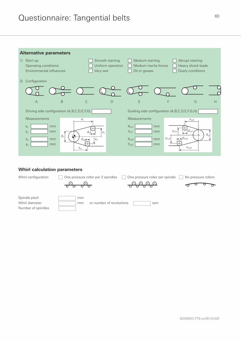
60
6026BRO.PTB-en0612HQR
Questionnaire: Tangential belts
Whirl confi guration One pressure roller per 2 spindles One pressure roller per spindle No pressure rollers
Spindle pitch mm
Whirl diameter mm or number of revolutions rpm
Number of spindles
Whirl calculation parameters
1) Start up: Smooth starting Medium starting Abrupt starting
Operating conditions: Uniform operation Medium inertia forces Heavy shock loads
Environmental infl uences: Very wet Oil or grease Dusty conditions
2) Confi guration
A B C D E F G H
Alternative parameters
Driving side confi guration (A,B,C,D,E,F,G)
Measurements
xt mm
yt mm
xs mm
ys mm
Guiding side confi guration (A,B,C,D,E,F,G,H)
Measurements
Xm1 mm
Ym1 mm
Xm2 mm
Ym2 mm
dt
ds
d1
xs
ys
yt
xt xm1
dm1ym1
dm2ym2
du
xm2

Notes

Notes

The Habasit solution
Customers first At Habasit we understand that our success depends on your success. This is why we offer solutions, not just products; partnership, not just sales.Since our foundation in 1946, Habasit has brought this understanding of customer needs to life every day and for every application. That’s why we’re the No. 1 in belting today. Worldwide.Learn more on www.habasit.com
Committed to innovationBecause our customers’ belting challenges and needs never cease, we consistently dedicate a substantial percentage of our employees and resources to the research and development of new products and solutions.
Certified for qualityWe deliver the highest quality standards not only in our products and solutions, but also in our employees’ daily work processes. Habasit AG is certified according to ISO 9001:2008.
Worldwide leading product range Habasit offers the largest selection of belting, conveying, processing and complementary products in the industry. Our response to any request is nothing less than a specific, tailor-made solution.
Fabric based conveyor and processing beltsHabaFLOW®
Plastic modular beltsHabasitLINK®
Power transmission belts HabaDRIVE®
Timing beltsHabaSYNC®
Chains (slat and conveyor chains)HabaCHAIN®
Profiles, Guides, Wear strips HabiPLAST®
Machine tapes
Seamless belts
Round belts
Fabrication tools (joining tools)
GearmotorsElectric motorsMotion control
Positive drive conveyor and processing beltsHabasit CleandriveTM

HeadquartersHabasit AG Römerstrasse 1CH-4153 Reinach, Switzerland Phone +41 61 715 15 15Fax +41 61 715 15 55E-mail [email protected] www.habasit.com
Registered trademarks Copyright Habasit AGSubject to alterationsPrinted in SwitzerlandPublication data: 6026BRO.PTB-en0612HQR
AustriaHabasit GmbHWienPhone: +43 1 690 66www.habasit.at
BelgiumHabasit Belgium N.V.ZaventemPhone: +32 27 250 430www.habasit.be
CanadaHabasit Canada Ltd.OakvillePhone: +1 905 827 41 31www.habasit.ca
ChinaHabasit East Asia Ltd.Hong KongPhone: +85 221 450 150 www.habasit.com.hk
Habasit (Shanghai) Co. Ltd.ShanghaiPhone: +8621 5488 1228Phone: +8621 5488 1218www.habasit.com.hk
FranceHabasit France S.A.S.MulhousePhone: +33 389 338 903 www.habasit.fr
GermanyHabasit GmbHEppertshausenPhone: +49 6071 969 0 www.habasit.de
IndiaHabasit-Iakoka Pvt. Ltd.CoimbatorePhone: +91 422 262 78 79www.habasitiakoka.com
ItalyHabasit Italiana SpACustomer Care:Phone: 199 199 333For int. calls: +39 0438 911 444 www.habasit.it
JapanHabasit Nippon Co. Ltd.YokohamaPhone: +81 45 476 0371www.habasit.co.jp
NetherlandsHabasit Netherlands BVNijkerkPhone: +31 332 472 030 www.habasit.nl
New Zealand Habasit Australasia Ltd.Hornby Phone: +64 3348 5600 www.habasit.co.nz
NorwayHabasit Norge A/S, OsloPhone: +47 815 58 458www.habasit.no
PolandHabasit Polska Sp. zo.o.Dąbrowa GórniczaPhone: +48 32639 02 40www.habasit.pl
RussiaOOO Habasit Ltd.St. PetersburgPhone: +7 812 600 40 80www.habasit.ru
SingaporeHabasit Far East Pte. Ltd.SingaporePhone: +65 686 255 66 www.habasit.com.sg
SpainHabasit Hispanica S.A.Barberà del VallèsPhone: +34 937 191 912 www.habasit.es
SwedenHabasit ABHindasPhone: +46 30 122 600www.habasit.se
SwitzerlandHabasit GmbHReinachPhone: +41 61 577 51 00www.habasit.ch
TaiwanHabasit Rossi (Taiwan) Ltd.Taipei HsienPhone: +886 2 2267 0538www.habasit.com.tw
TurkeyHabasit Kayis San. Ve Tic. Ltd. Sti.Yenibosna-Bahcelievler-IstanbulPhone: +90 212 654 94 04www.habasit.com.tr
UkraineHabasit UkrainaVinnicaPhone: +38 0432 58 47 35www.habasit.ua
United Kingdom and IrelandHabasit (UK) Ltd.Silsden Phone: +44 844 835 9555 www.habasit.co.uk
USAHabasit America Conveyor belts, power transmission belts, gearmotors Suwanee, Georgia Phone: +1 800 458 6431 www.habasitamerica.com
Habasit America Seamless belts, timing belts Middletown, Connecticut Phone: +1 860 632 2211 www.habasitamerica.com
Rossi is one of Europe’s largest manufacturers of gear reducers, gearmotors, inverters, standard and brakemotors, and is a member of the Habasit Group.
Rossi S.p.A. Via Emilia Ovest 915/A41123 Modena – ItalyPhone: +39 059 33 02 [email protected]