POWER TRANSFORMER - West Bengal State Electricity ...wbsetcl.in/SubStation/POWER TRANSFORMER.pdf ·...
43
WBSETCL / TECH SPEC / Rev.-1 Page 1 of 43 Power Transformer POWER TRANSFORMER March 2015 Engineering Department WEST BENGAL STATE ELECTRICITY TRANSMISSION COMPANY LIMITED Regd. Office: VidyutBhawan, Block – DJ, Sector-II, Bidhannagar, Kolkata – 700091. CIN: U40101WB2007SGC113474; Website: www.wbsetcl.in
Transcript of POWER TRANSFORMER - West Bengal State Electricity ...wbsetcl.in/SubStation/POWER TRANSFORMER.pdf ·...
WBSETCL / TECH SPEC / Rev.-1 Page 1 of 43 Power Transformer
POWER TRANSFORMER
March 2015
Engineering Department
WEST BENGAL STATE ELECTRICITY TRANSMISSION COMPANY LIMITED
Regd. Office: VidyutBhawan, Block – DJ, Sector-II, Bidhannagar, Kolkata – 700091.
CIN: U40101WB2007SGC113474; Website: www.wbsetcl.in
WBSETCL / TECH SPEC / Rev.-1 Page 2 of 43 Power Transformer
TECHNICAL SPECIFICATION FOR
POWER TRANSFORMER
1. SCOPE:
This specification covers design, engineering, manufacture & assembly of 3-Phase, 400/220/33 KV 315MVA, 220/132/33 KV 200 & 160 MVA, 220/33 KV 80 MVA & 50 MVA,
132/33 KV 20MVA, 31.5 MVA & 50 MVA Power Transformer complete with all fittings and
accessories required for efficient and trouble free operations of the transformer, testing at manufacturer’s works and customer’s premises, supply, loading at factory, delivery at site,
unloading, handling, dragging for proper storage at site on the plinth of transformer if the same is ready at respective site or at suitable location as per direction of site-in-charge of
customer.
2. GENERAL REQUIREMENT:
The Transformer shall be multi-winding, oil immersed complying as per Specific Technical parameters and suitable for outdoor installation.
Rated Capacity and Voltage of the Transformers shall be guided by the respective Tender Documents issued time to time. The specification covers for the following transformers as per present requirement of the company:
a) 315MVA - 400/220/33KV and 200/160 MVA - 220/132/33 KV Auto Transformer with loaded
33 KV tertiary winding.
b) 50MVA/80MVA - 220/33KV, 20MVA / 31.5 MVA / 50 MVA - 132/33KV.
SPECIFIC REQUIREMENT:
(i) Type Test: The transformers should be Type Tested as per IS 2026 or IEC 60076 in
conjunction with their relevant Part. Necessary test documents of previously tested
similar transformer within last 5 years from date of NIT shall have to be submitted with the bid.
(ii) Dynamic Effect of Short Circuit
For 400 kV Class Auto transformer:
Bidder should have successfully carried out Dynamic Short Circuit test on three phase bank of any rating of 400/220/33kV or higher voltage class of Auto transformer as on
the date of NIT and shall enclose the relevant Test Report and certificate along with bid. In case bidder has not successfully tested any rating of 400/220/33kV or higher
voltage class Auto transformer for Dynamic Short Circuit test, their bid shall be considered technically non responsive .This shall be applicable for 400kV class Auto
transformer of all rating.
WBSETCL / TECH SPEC / Rev.-1 Page 3 of 43 Power Transformer
For 220 kV Class Transformer:
Bidders should have successfully carried out Dynamic Short Circuit Test on any rating of 220 kV or above class transformer as on the date of NIT and shall enclose the relevant Test Report and Certificate along with bid. In case bidder has not successfully tested 220 kV or above class transformer for Dynamic Short Circuit Test, their bid shall be considered technically non- responsive. This shall be applicable for 220 kV class
Transformer of all rating.
For 132 kV Class Transformer:
Bidders should have successfully carried out Dynamic Short Circuit Test on any rating of
132kV or above class transformer as on the date of NIT and shall enclose the relevant Test Report and Certificate along with bid. In case bidder has not successfully tested 132kV or above class transformer for Dynamic Short Circuit Test, their bid shall be considered technically non- responsive. This shall be applicable for 132kV class
Transformer of all rating.
(iii) Sweep Frequency Response Analysis (SFRA/FRA) shall have to be carried out as
special test for each transformer at manufacturer’s premises in presence of representative of WBSETCL free of cost. Test result shall have to be handed over to
WBSETCL. Before commissioning of the Transformer at site, the same SFRA/FRA test will
have to be carried by the test engineers of the manufacturer in presence of customer’s representative for comparing the results to take the decisions of the commissioning.
The Testing Engineers & FRA kit for such pre-commissioning site testing shall have to be arranged by the manufacturer free of cost.
(iv) Tests at Manufacturer’s works: The Transformers shall be subjected to type & routine test, special tests and no load & load loss measurement as per relevant IS as
mentioned in the Clause “TEST AT FACTORY AND TEST CERTIFICATES”.
(v) Guaranteed Technical Particulars: The Bidder shall furnish all guaranteed technical
particulars as called for in this specification along with each copy of Bid submission. Bids lacking information in this respect may not be considered.
(vi) Core Materials: Core materials should be directly procured from either the manufacturer
or their accredited reputed marketing organization and not through any agent.
3. STANDARD:
The Power Transformer covered under this specification shall comply with the requirements of the latest edition of following Standards:
i) IS:2026 (Part I to IV) - Specification for Power Transformer
ii) IS:2099 & IS:3347 - Bushing for alternating voltage above 1000 volt
iii) IS : 6600 - Guide for loading of oil immersed transformer
iv) IS : 335 - Specification for transformer oil
v) CBIP - Manual on transformer.
vi) IEC-60076 - Power Transformer
vii) IEC-60214 - On Load Tap changer.
viii) IEC-354 - Loading Guide for Oil immersed Transformer
ix) IEC-551 - Tr. Sound Level.
WBSETCL / TECH SPEC / Rev.-1 Page 4 of 43 Power Transformer
4. DEVIATION:
Normally the offer should be as per Technical Specification without any deviation. But any
deviation felt necessary to improve performance, efficiency and utility of equipment must be
mentioned in the
'Deviation Schedule' with reasons, duly supported by documentary evidences and advantages of such Deviation shall be mentioned. Such deviations suggested may or may not be accepted. But deviations not mentioned in Deviation Schedule will not be considered.
5. GENERAL DESIGN:
a) The Transformer and accessories shall be designed to facilitate easy inspection, cleaning and repairs. All fittings and accessories shall be designed to ensure satisfactory operation under worst conditions of load and voltage as may be met under working conditions in the system.
b) All materials used shall be of best quality and of the class most suitable for working under the conditions specified. It shall withstand the variations of temperature and atmospheric conditions without undue stressing etc. i.e. not affecting the workability/durability of the various parts of the transformer.
c) All outdoor fittings and accessories, including bushings insulators with their mounting, shall be so designed as to avoid pockets in which water can collect. All electrical connections shall be of ample cross sections for carrying the specified currents continuously without undue heating. All fixing bolts and screws shall be reliable under worst conditions of operations.
d) Transformers shall be suitable for continuous operation with a frequency of 50 Hz and
variation of± 3% without exceeding specified temperature rise.
e) Transformer with tertiary winding and all its accessories including Bushing CTs etc. shall be design to withstand without injury, the mechanical and thermal effects and any external short circuit to earth and of short circuits at the terminals of any winding for a period of 3 Sec. The short circuit level of HV & IV system to which the subject transformer will be connected is 40KA (Sym, rms, 3Ph. Fault on 400KV and 220KV) and 31.5KA (Sym., rms, 3 Ph. fault on 132KV). Transformer shall be capable of withstanding thermal and mechanical stresses caused by symmetrical or asymmetrical faults on any winding.
f) For parallel operation with other transformers, necessary provision is to be kept in
transformer RTCC panel for tap changing operation in any of
Master/Follower/Independent mode.
g) Clearances of line terminals in Air:
WBSETCL / TECH SPEC / Rev.-1 Page 5 of 43 Power Transformer
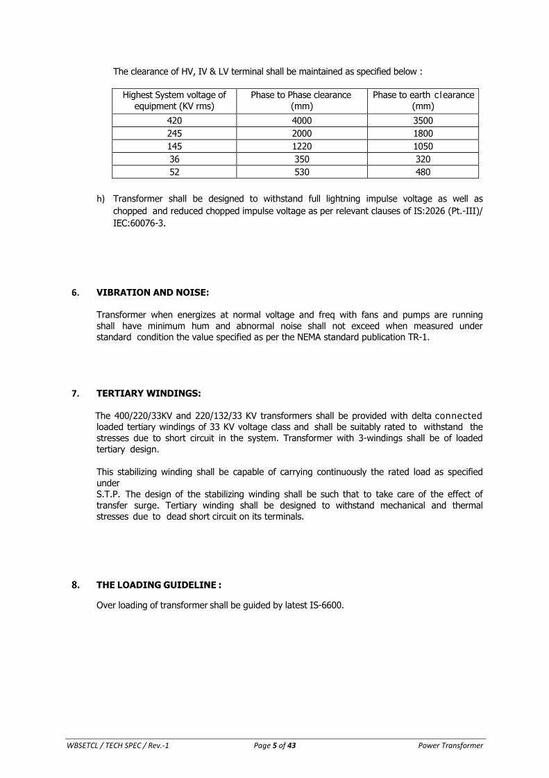
The clearance of HV, IV & LV terminal shall be maintained as specified below :
Highest System voltage of
equipment (KV rms)
Phase to Phase clearance
(mm)
Phase to earth c learance
(mm)
420 4000 3500
245 2000 1800
145 1220 1050
36 350 320
52 530 480
h) Transformer shall be designed to withstand full lightning impulse voltage as well as
chopped and reduced chopped impulse voltage as per relevant clauses of IS:2026 (Pt.-III)/
IEC:60076-3.
6. VIBRATION AND NOISE:
Transformer when energizes at normal voltage and freq with fans and pumps are running
shall have minimum hum and abnormal noise shall not exceed when measured under standard condition the value specified as per the NEMA standard publication TR-1.
7. TERTIARY WINDINGS:
The 400/220/33KV and 220/132/33 KV transformers shall be provided with delta connected loaded tertiary windings of 33 KV voltage class and shall be suitably rated to withstand the
stresses due to short circuit in the system. Transformer with 3-windings shall be of loaded
tertiary design.
This stabilizing winding shall be capable of carrying continuously the rated load as specified
under S.T.P. The design of the stabilizing winding shall be such that to take care of the effect of
transfer surge. Tertiary winding shall be designed to withstand mechanical and thermal stresses due to dead short circuit on its terminals.
8. THE LOADING GUIDELINE :
Over loading of transformer shall be guided by latest IS-6600.
WBSETCL / TECH SPEC / Rev.-1 Page 6 of 43 Power Transformer
9. TEMPERATURE RISE:
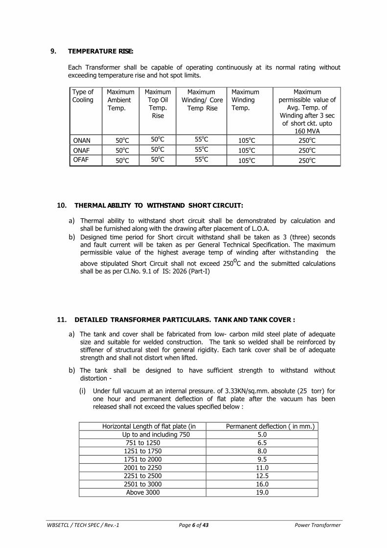
Each Transformer shall be capable of operating continuously at its normal rating without
exceeding temperature rise and hot spot limits.
Type of
Cooling
Maximum
Ambient
Temp.
Maximum
Top Oil
Temp.
Rise
Maximum
Winding/ Core
Temp Rise
Maximum
Winding
Temp.
Maximum
permissible value of Avg. Temp. of
Winding after 3 sec
of short ckt. upto 160 MVA
ONAN 50oC 50oC 55oC 105oC 250oC
ONAF 50oC 50oC 55oC 105oC 250oC
OFAF 50oC 50oC 55oC 105oC 250oC
10. THERMAL ABILITY TO WITHSTAND SHORT CIRCUIT:
a) Thermal ability to withstand short circuit shall be demonstrated by calculation and shall be furnished along with the drawing after placement of L.O.A.
b) Designed time period for Short circuit withstand shall be taken as 3 (three) seconds and fault current will be taken as per General Technical Specification. The maximum permissible value of the highest average temp of winding after withstanding the
above stipulated Short Circuit shall not exceed 250oC and the submitted calculations
shall be as per Cl.No. 9.1 of IS: 2026 (Part-I)
11. DETAILED TRANSFORMER PARTICULARS. TANK AND TANK COVER :
a) The tank and cover shall be fabricated from low- carbon mild steel plate of adequate
size and suitable for welded construction. The tank so welded shall be reinforced by stiffener of structural steel for general rigidity. Each tank cover shall be of adequate
strength and shall not distort when lifted.
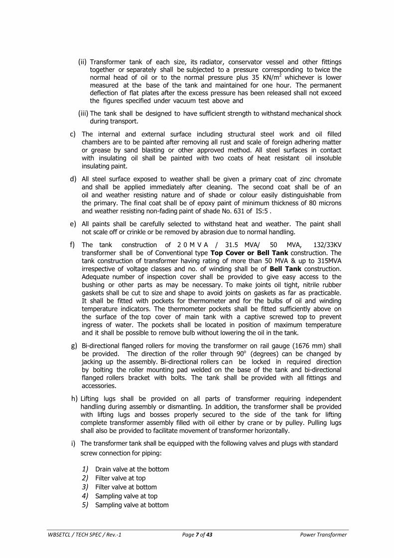
b) The tank shall be designed to have sufficient strength to withstand without
distortion -
(i) Under full vacuum at an internal pressure. of 3.33KN/sq.mm. absolute (25 torr) for
one hour and permanent deflection of flat plate after the vacuum has been released shall not exceed the values specified below :
Horizontal Length of flat plate (in mm.)
Permanent deflection ( in mm.)
Up to and including 750 5.0
751 to 1250 6.5
1251 to 1750 8.0
1751 to 2000 9.5
2001 to 2250 11.0
2251 to 2500 12.5
2501 to 3000 16.0
Above 3000 19.0
WBSETCL / TECH SPEC / Rev.-1 Page 7 of 43 Power Transformer
(ii) Transformer tank of each size, its radiator, conservator vessel and other fittings together or separately shall be subjected to a pressure corresponding to twice the normal head of oil or to the normal pressure plus 35 KN/m2 whichever is lower measured at the base of the tank and maintained for one hour. The permanent deflection of flat plates after the excess pressure has been released shall not exceed the figures specified under vacuum test above and
(iii) The tank shall be designed to have sufficient strength to withstand mechanical shock during transport.
c) The internal and external surface including structural steel work and oil filled chambers are to be painted after removing all rust and scale of foreign adhering matter
or grease by sand blasting or other approved method. All steel surfaces in contact with insulating oil shall be painted with two coats of heat resistant oil insoluble
insulating paint.
d) All steel surface exposed to weather shall be given a primary coat of zinc chromate
and shall be applied immediately after cleaning. The second coat shall be of an oil and weather resisting nature and of shade or colour easily distinguishable from
the primary. The final coat shall be of epoxy paint of minimum thickness of 80 microns
and weather resisting non-fading paint of shade No. 631 of IS:5 .
e) All paints shall be carefully selected to withstand heat and weather. The paint shall
not scale off or crinkle or be removed by abrasion due to normal handling.
f) The tank construction of 2 0 M V A / 31.5 MVA/ 50 MVA, 132/33KV
transformer shall be of Conventional type Top Cover or Bell Tank construction. The tank construction of transformer having rating of more than 50 MVA & up to 315MVA
irrespective of voltage classes and no. of winding shall be of Bell Tank construction. Adequate number of inspection cover shall be provided to give easy access to the
bushing or other parts as may be necessary. To make joints oil tight, nitrile rubber
gaskets shall be cut to size and shape to avoid joints on gaskets as far as practicable. It shall be fitted with pockets for thermometer and for the bulbs of oil and winding
temperature indicators. The thermometer pockets shall be fitted sufficiently above on the surface of the top cover of main tank with a captive screwed top to prevent
ingress of water. The pockets shall be located in position of maximum temperature and it shall be possible to remove bulb without lowering the oil in the tank.
g) Bi-directional flanged rollers for moving the transformer on rail gauge (1676 mm) shall
be provided. The direction of the roller through 90o
(degrees) can be changed by jacking up the assembly. Bi-directional rollers can be locked in required direction
by bolting the roller mounting pad welded on the base of the tank and bi-directional flanged rollers bracket with bolts. The tank shall be provided with all fittings and
accessories.
h) Lifting lugs shall be provided on all parts of transformer requiring independent
handling during assembly or dismantling. In addition, the transformer shall be provided with lifting lugs and bosses properly secured to the side of the tank for lifting
complete transformer assembly filled with oil either by crane or by pulley. Pulling lugs
shall also be provided to facilitate movement of transformer horizontally.
i) The transformer tank shall be equipped with the following valves and plugs with standard
screw connection for piping:
1) Drain valve at the bottom
2) Filter valve at top
3) Filter valve at bottom
4) Sampling valve at top
5) Sampling valve at bottom
WBSETCL / TECH SPEC / Rev.-1 Page 8 of 43 Power Transformer
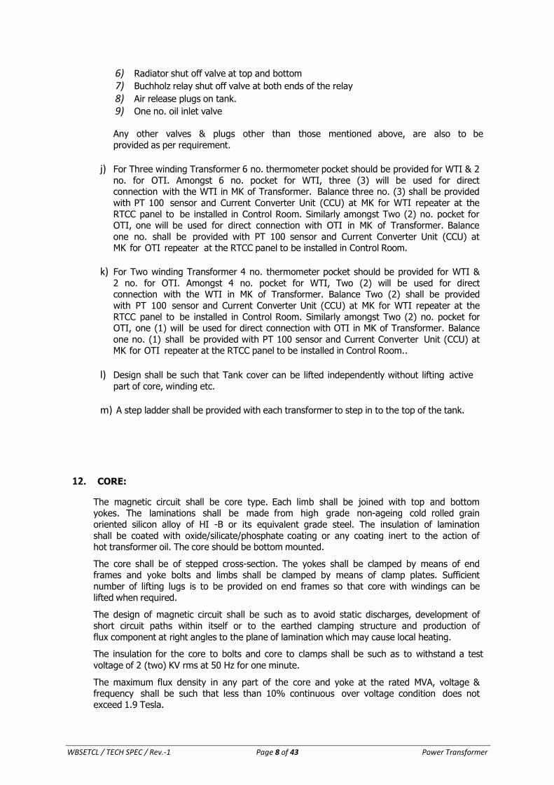
6) Radiator shut off valve at top and bottom
7) Buchholz relay shut off valve at both ends of the relay
8) Air release plugs on tank.
9) One no. oil inlet valve
Any other valves & plugs other than those mentioned above, are also to be
provided as per requirement.
j) For Three winding Transformer 6 no. thermometer pocket should be provided for WTI & 2
no. for OTI. Amongst 6 no. pocket for WTI, three (3) will be used for direct connection with the WTI in MK of Transformer. Balance three no. (3) shall be provided
with PT 100 sensor and Current Converter Unit (CCU) at MK for WTI repeater at the
RTCC panel to be installed in Control Room. Similarly amongst Two (2) no. pocket for OTI, one will be used for direct connection with OTI in MK of Transformer. Balance
one no. shall be provided with PT 100 sensor and Current Converter Unit (CCU) at MK for OTI repeater at the RTCC panel to be installed in Control Room.
k) For Two winding Transformer 4 no. thermometer pocket should be provided for WTI &
2 no. for OTI. Amongst 4 no. pocket for WTI, Two (2) will be used for direct connection with the WTI in MK of Transformer. Balance Two (2) shall be provided
with PT 100 sensor and Current Converter Unit (CCU) at MK for WTI repeater at the
RTCC panel to be installed in Control Room. Similarly amongst Two (2) no. pocket for OTI, one (1) will be used for direct connection with OTI in MK of Transformer. Balance
one no. (1) shall be provided with PT 100 sensor and Current Converter Unit (CCU) at MK for OTI repeater at the RTCC panel to be installed in Control Room..
l) Design shall be such that Tank cover can be lifted independently without lifting active
part of core, winding etc.
m) A step ladder shall be provided with each transformer to step in to the top of the tank.
12. CORE:
The magnetic circuit shall be core type. Each limb shall be joined with top and bottom yokes. The laminations shall be made from high grade non-ageing cold rolled grain
oriented silicon alloy of HI -B or its equivalent grade steel. The insulation of lamination
shall be coated with oxide/silicate/phosphate coating or any coating inert to the action of hot transformer oil. The core should be bottom mounted.
The core shall be of stepped cross-section. The yokes shall be clamped by means of end frames and yoke bolts and limbs shall be clamped by means of clamp plates. Sufficient
number of lifting lugs is to be provided on end frames so that core with windings can be
lifted when required.
The design of magnetic circuit shall be such as to avoid static discharges, development of
short circuit paths within itself or to the earthed clamping structure and production of
flux component at right angles to the plane of lamination which may cause local heating.
The insulation for the core to bolts and core to clamps shall be such as to withstand a test
voltage of 2 (two) KV rms at 50 Hz for one minute.
The maximum flux density in any part of the core and yoke at the rated MVA, voltage & frequency shall be such that less than 10% continuous over voltage condition does not exceed 1.9 Tesla.
WBSETCL / TECH SPEC / Rev.-1 Page 9 of 43 Power Transformer
For consideration of over fluxing, the transformer shall be suitable for continuous
operation for values of over fluxing at (i) 110% (ii) one minute for 125% and (iii) 5 seconds for 140% of rated voltage.
The prime core materials are only to be used. Bidder’s should furnish following document as applicable as a proof towards use of prime Core material to be submitted before the
stage inspection:
(a) Invoice of supplier (b) Mill’s test certificate
(c) Packing List
(d) Bill of lading
(e) Bill of entry certificate by Custom.
(f) Description of material, electrical analysis, physical inspection, certificate for surface
defects, thickness and width of the materials.
(g) Place of cutting of core materials
13. WINDINGS:
The Material of winding conductor should be of electrolytic grade copper of minimum
99.90% purity and free from scales, spills, splits and other defects. The windings shall be
so designed that all coil assemblies of identical voltage ratings shall be interchangeable and field repair is possible. The coils shall be supported between adjacent sections by
insulating spacers, and the barriers. Bracing and other insulation used in the assembly of the windings shall be arranged to ensure a free circulation of the oil and to reduce hot
spots in the windings. The stacks of windings shall receive adequate shrinkage treatment before final assembly and the same shall be assembled in dust controlled chamber.
The insulation of the coils shall be such as to withstand the full electrical strength of the
windings. All materials used in the insulation and assembly of the windings shall be insoluble, non-catalytic and chemically inactive in the hot transformer oil, and shall not
soften or otherwise be adversely affected under the operating conditions. The dielectric strength of winding insulation shall confirm to values given in IS: 2026, as amended up to
date, or as per specific Technical Parameters.
All threaded connections shall be provided with locking facilities.
All leads from the windings to the terminal board and bushings shall be rigidity supported
to prevent injury from vibration. Guide tubes shall be used where practicable.
The windings shall be clamped securely in place so that they will not be displaced or
deformed during short circuits. The assembled core and windings shall be vacuum dried and suitably impregnated with insulating oil. The copper conductors used in the coil
assembly shall be best suited to the requirements and all permanent current carrying
joints in the windings and the leads shall be welded or brazed. Oil ducts shall be such as will not impede the free circulation of oil through windings assembly.
The conductor shall be transposed at sufficient intervals in order to minimize eddy currents and to equalize the distribution of currents and temperature along the winding.
WBSETCL / TECH SPEC / Rev.-1 Page 10 of 43 Power Transformer
14. TAP CHANGING MECHANISM:
The transformer shall give full load output on all taps. The transformer shall operate
without danger on any particular tapping at the rated MVA within a voltage variation of ±10% of the rated nominal voltage.
For 132/33KV & 220/33 KV transformer ON LOAD TAP CHANGER with bi-directional power flow shall be provided on the 132KV voltage winding & 220KV winding respectively. The
tapping range shall be +10% and –10% in 1.25% equal steps. Remote Tap Changer
Panel shall also be provided to be installed at our Control Room.
For 220/132/33 KV & 400/220/33KV Auto Transformer Tap coil with bi-directional power
flow shall be provided at 132 KV and 400 KV sides respectively of the transformer. The tapping range shall be + 10% and –10% in 1.25% equal steps.
Remote Tap Changer Panel shall also be provided to be installed at our Control Room.
15. ON LOAD TAP CHANGER:
This shall be designed suitable for remote control operation from RTCC Panel in the control room to be supplied by the manufacturer in addition to being capable of local
manual as well as local electrical operation.
The on-load tap changer shall include the following :-
a) An oil immersed tap selector and arcing switch or arc suppressing tap selector,
provided with reactor or resistor for reduction of make and break arcing voltages and short circuits.
b) Motor driven mechanism
c) Control and protection devices
d) Local /Remote tap changer position indicator
e) Manual/Electrical operating device.
The on-load tap changer shall be designed so that the contacts do not interrupt arc within the main tank of the transformer. The tap selector and arcing switch or arc suppressing
tap selector switch shall be located in one or more oil filled compartments. The compartment shall be provided with Oil Surge relay. Those compartments shall be designed
so as to prevent the oil in tap selector compartment from mixing with the oil in the transformer main tank.
An oil surge relay with trip float arrangement shall be provided for the OLTC unit.
The tap changer shall be capable of permitting parallel operation with either existing or future transformers of the same type as Master or Follower.
The manual operating device shall be so located on the transformer that it can be operated by a man standing at the level of the transformer track. It shall be strong and robust in
construction.
The control scheme for the tap changer shall be provided for independent control of the tap changers when the transformers are in independent service. In addition, provision shall
be made so that under parallel operation the tap changer will give alarm and visual indication for becoming out of step. Visual indication during the operation of motor shall
also be incorporated. The tap change control must ensure step by step operation under all
operating conditions.
Necessary interlock blocking independent control when the units are in parallel shall be
provided.
WBSETCL / TECH SPEC / Rev.-1 Page 11 of 43 Power Transformer
Under parallel operation, as may occur if the contactor controlling one tap changer sticks,
the arrangement must be such as to switch off supply to the motor so that an out of step condition is limited to one tap difference between the units. Details of out of step protection
provided for the taps should be furnished in the bid.
The contactors and associated gear for the tap change driving motors shall be housed in a
local kiosk mounted on the transformer. The motors shall be suitable for operation with
3-phase 400 volts, 50 cycle external power supply.
Conventional RTCC Panel:
The supplier shall furnish, in addition to the equipment above, the following accessories mounted in a separate Remote Tap Changer Control (RTCC) panel to be installed in each
of the WBSETCL’s Control Room for remote operation.
a) Raise and Lower Push Button Switch
b) Remote tap position indicator and other required devices. One chart showing the voltage corresponding to tap position indicator shall be engraved on a metal sheet
and the same shall be fixed near the tap position indicator on the RTCC (Panel).
c) An indication lamp showing tap changing in a progress
d) Master, Follower and Independent selecting switch and other accessories required for complete operation of tap changer.
e) Name plate of each component & relays
f) Winding & Oil temperature (0o –150oC) repeaters to be connected to winding and oil Temperature meter housed in the main Transformer Marshalling Box at outdoor. In
addition to above necessary arrangements are to be made in RTCC panel for Hot spot temperature indication and alarm by optical sensor method as mentioned in clause 27.
Complete particulars of the tap changing gear including the capacity of the motor shall be stated in GTP. An under voltage relay shall be incorporated to monitor the 110 Volt AC
control circuit voltage of tap changer. Audible Alarm and annunciation shall be provided for failure of control circuit supply, failure of 400 V AC supply to the motor. All the relays
requisite for remote tap change operation shall be provided in RTCC panel. The OLTC should
have been Type Tested.
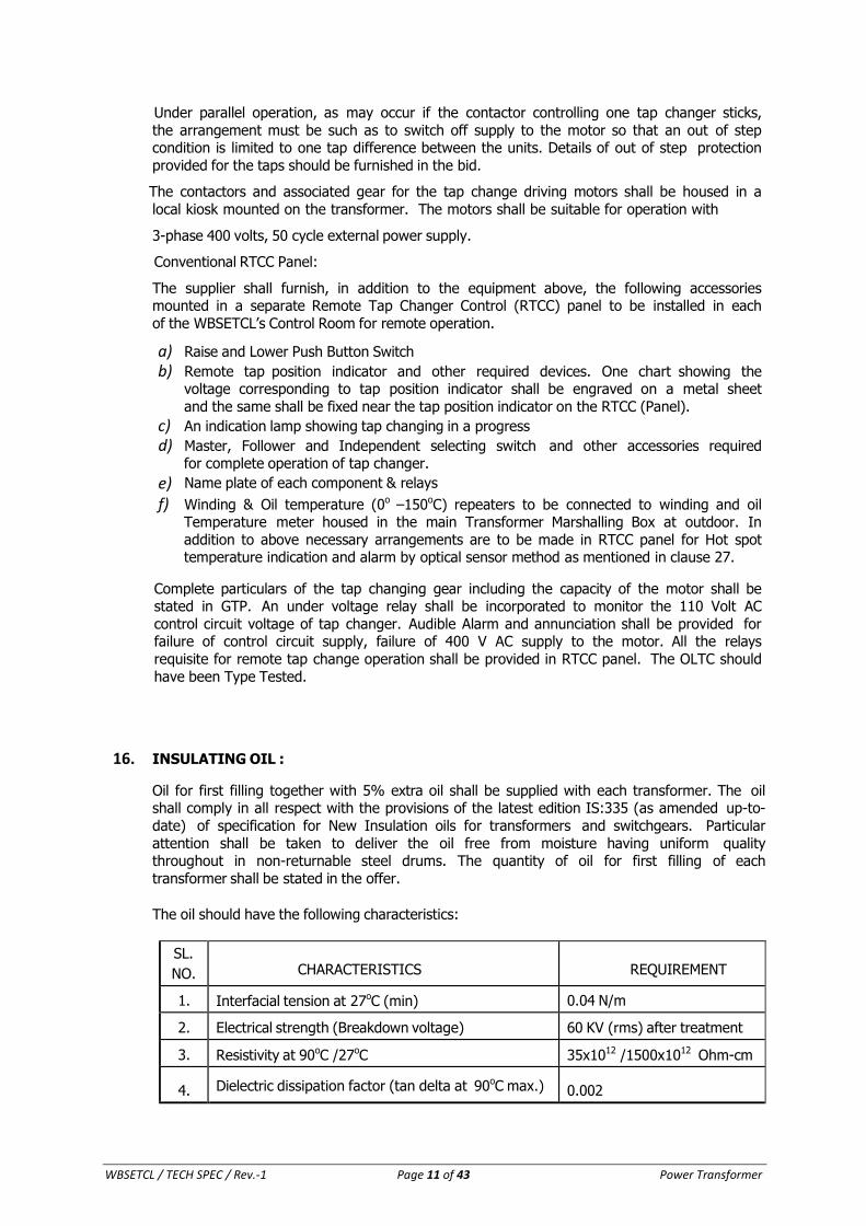
16. INSULATING OIL :
Oil for first filling together with 5% extra oil shall be supplied with each transformer. The oil shall comply in all respect with the provisions of the latest edition IS:335 (as amended up-to-
date) of specification for New Insulation oils for transformers and switchgears. Particular
attention shall be taken to deliver the oil free from moisture having uniform quality throughout in non-returnable steel drums. The quantity of oil for first filling of each
transformer shall be stated in the offer.
The oil should have the following characteristics:
SL.
NO. CHARACTERISTICS REQUIREMENT
1. Interfacial tension at 27oC (min) 0.04 N/m
2. Electrical strength (Breakdown voltage) 60 KV (rms) after treatment
3. Resistivity at 90oC /27oC 35x1012 /1500x1012 Ohm-cm
4. Dielectric dissipation factor (tan delta at 90oC max.) 0.002
WBSETCL / TECH SPEC / Rev.-1 Page 12 of 43 Power Transformer
After site processing through filtration and before commissioning, the moisture content
shall be as follows :
a) Less than 72.5 KV : 25 ppm
b) 72.5 KV to 145 KV : 20 ppm
c) Above 145 KV : 15 ppm
17. CONSERVATOR VESSEL:
a) The conservator is a vessel for oil preservation. The oil level in the conservator shall not be below the level of the H.V. bushing caps unless the bushings are of oil sealed type construction. The size of the conservator tank shall have adequate capacity with highest and lowest visible level to meet the requirement of expansion of total cold oil volume in the transformer and cooling equipment from minimum ambient temperature to 100oC.
b) The conservator shall have one filter valves at suitable location, in addition to the valve specified in the accessories for the main tank. The conservator with sump shall also have a small drain valve and sampling cock, the latter so arranged as not to interfere with oil lines. The oil level gauge shall be mounted on the conservator. The oil level at gauge shall have three indication viz., oil level at 30oC shall be marked on the gauge and indicating range shall be minimum to maximum level.
c) There shall be one “Atmoseal type” sealing to prevent direct contact of transformer oil with the atmospheric air to retard oxidation and contamination of oil.
d) The oil connection from the transformer tank to the conservator vessel shall
be arranged at a rising angle of 3 to 9 degree to the horizontal upto the Buchhloz relay. The inside diameter shall be 50mm/80mm as per capacity of the transformer
and IS: 3639.
e) Valves shall be provided at the conservator to cut off the oil supply to the transformer after providing a straight run of pipe for at least five times internal diameter of the pipe on the tank side of the Buchholz relay and at least three times the internal diameter of the pipe on the conservator side of the Buchholz relay. The pipe connecting the transformer tank with conservator will project above the lowest point in the conservator such that the portion below the pipe acts as a sump where the impurities in conservator will be collected.
f) Magnetic oil level gauge with low oil level alarm suitable for 220Volt ±10% DC supply
shall be provided.
g) Atmoseal type conservator shall be filled with oil to a level appropriate to the filling
temperature. The oil shall be separated from atmosphere by a flexible aircell of nitrile rubber reinforced with nylon cloth air cell. Flexible aircell of nitrile rubber shall be
able to withstand max temp of oil considering continuous operation as well as considering overloading of transformer as per relevant IS/IEC. The connection of air cell
to the top of the conservator is to be made by air proof seal to prevent entry of air to the
conservator.
h) OLTC Conservator shall have oil indicator made of glass.
i) Dehydrating Filter Breather: Conservator shall be fitted with a dehydrating filter breather. It shall be designed to facilitate the followings:
(i) Passage of air through silica gel.
(ii) Silica gel is isolated from atmosphere by an oil seal.
WBSETCL / TECH SPEC / Rev.-1 Page 13 of 43 Power Transformer
(iii) Two breathers (of identical size) shall be connected in parallel for main conservator tank. A stop valve shall be provided for each breather and also
for the common pipe line. The same arrangement shall be made for OLTC
tank conservator by providing adequate size of two identical breathers.
(iv) Breathers are to be maintained approx at a height of 1200 mm. above rail top level.
(v) Moisture absorption indicated by a change in colour of the silica gel can be
easily observed from ground level.
18. BUSHING :
Bushing shall have high factor of safety against leakage to ground and shall be so located
as to provide adequate electrical clearances between bushing and grounded parts. Bushings of identical voltage rating shall be interchangeable. All bushings shall be equipped
with suitable terminals of approved type and size and shall be suitable for bimetallic
connection, if necessary. The insulation class of the high voltage neutral bushing shall be properly coordinated with the insulation class of the neutral of the high voltage winding.
All main windings, tertiary windings and neural leads shall be brought out to outdoor through bushings which shall be so located that the full flashover strength will be utilised
and phase to phase and phase to earth clearance shall be more than minimum value specified below. Location and arrangement of bushing shall follow Indian Standards.
Each bushing shall be so coordinated with the transformer insulation that flashovers will
occur outside the tank.
All porcelain used in the bushings shall be made of the wet process, be homogeneous and
free from cavities or other flaws. The glazing shall be uniform in colour and free from blisters, burns, and other defects. Upper portion of Bushing made of Porcelain & lower
portion made of Epoxy/porcelain is also acceptable.
Bushings for 420KV, 245 KV and 145 KV & 52 KV voltage class shall be Oil Filled Condenser type and shall be hermetically sealed. HV Neutral bushing shall be of 36 KV
class for 400 KV & 220 KV class transformers. Bushing for 33 KV delta tertiary winding i.r.o. 160 MVA,200 MVA and 315 MVA Transformer shall be of 52 KV class and of Oil Filled
Condenser type and shall be hermetically sealed. All OIP bushing shall have provision
of measurement of capacitance and tan-delta without dismantling of the bushing. Rating plate of bushing shall be provided near each type of bushing with terminal marking and
physical position as per IS:2026. Bushing for 36KV shall be Solid porcelain or oil communicating type.
The electrical and mechanical characteristic of bushings shall conform to IS:2099 and
IS:3347. The characteristic of the oil used in the bushing shall be the same as that of the
oil in the transformer.
Main terminals shall be solder less and “Terminal Connectors” shall be as per cl. No. 19 of this technical specification. The spacing between the bushings must be adequate to prevent flashover between phases under all conditions of operation.
All bushings shall be suitable for heavily polluted atmosphere and minimum creepage
distance shall be taken as 25 mm per KV.
Where Bushing mounted Current Transformers are specified, the bushing shall be
removable without disturbing the current transformers.
Bushing Current Transformer:
i) Current transformer shall comply with IS:2705/IEC-185.
WBSETCL / TECH SPEC / Rev.-1 Page 14 of 43 Power Transformer
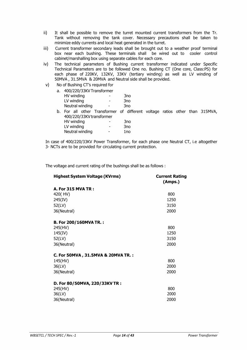
ii) It shall be possible to remove the turret mounted current transformers from the Tr. Tank without removing the tank cover. Necessary precautions shall be taken to
minimize eddy currents and local heat generated in the turret.
iii) Current transformer secondary leads shall be brought out to a weather proof terminal box near each bushing. These terminals shall be wired out to cooler control
cabinet/marshalling box using separate cables for each core.
iv) The technical parameters of Bushing current transformer indicated under Specific Technical Parameters are to be followed One no. Bushing CT (One core, Class:PS) for
each phase of 220KV, 132KV, 33KV (tertiary winding) as well as LV winding of
50MVA , 31.5MVA & 20MVA and Neutral side shall be provided.
v) No of Bushing CT’s required for
a. 400/220/33KV Transformer HV winding - 3no
LV winding - 3no Neutral winding - 3no
b. For all other Transformer of different voltage ratios other than 315MVA,
400/220/33KV transformer HV winding - 3no
LV winding - 3no Neutral winding - 1no
In case of 400/220/33KV Power Transformer, for each phase one Neutral CT, i.e altogether
3- NCTs are to be provided for circulating current protection.
The voltage and current rating of the bushings shall be as follows :
Highest System Voltage (KVrms)
Current Rating
(Amps.)
A. For 315 MVA TR :
420( HV) 800
245(IV) 1250
52(LV) 3150
36(Neutral) 2000
B. For 200/160MVA TR. :
245(HV) 800
145(IV) 1250
52(LV) 3150
36(Neutral) 2000
C. For 50MVA , 31.5MVA & 20MVA TR. :
145(HV) 800
36(LV) 2000
36(Neutral)
2000
D. For 80/50MVA, 220/33KV TR :
245(HV) 800
36(LV) 2000
36(Neutral) 2000
WBSETCL / TECH SPEC / Rev.-1 Page 15 of 43 Power Transformer
The minimum withstand value of cantilever load of bushings for 60 sec. shall be as follows
(refer IS:2099-1986 Cl. 5.5)
420KV - 2500N
245KV - 1600N(for 315MVA Tr.) & 1250N (for 200/160MVA TR).
145KV - 1250N 52KV - 3150N
36KV - 1250N/2000N
19. TERMINAL CONNECTOR:
i) The bushing shall be equipped with suitable terminals for connector as specified herein.
ii) Each terminal (including the neutral) shall be distinctly marked on both the primary and
secondary side in accordance with the diagram of connection supplied with the transformers.
iii) Vertical/horizontal/universal type bi-metallic, rigid connector for bushing stud shall be provided.
iv) Clamp and connector shall be made from Cold forged Aluminum Alloy Plate i.e Extruded Aluminum Clamp and Connector shall be processed through Cold forging for 220KV,
132KV, 52KV & 36KV Bushing and Casting type connector for 400KV class bushing.
v) The Nuts & Bolts associated with equipment of connector pieces shall be MS Hot dip
galvanized. Quality of Nuts & bolts shall conform to relevant IS of latest edition.
vi) Minimum thickness at any point of current carrying part of any clamp & connector shall not be less than 12mm.
vii) From outermost hole edge to nearest edge of any clamp & connector the distance shall not be less than 10mm.
viii) The current density of Aluminum/Copper shall be considered as 0.75/1.75 A/sq.mm.
ix) Minimum thickness of Bimetal in bimetallic connection shall be 2mm.
x) Approved vendor for Clamp & Connector are mentioned in WBSETCL portal.
20. COOLING SYSTEM :
Type of cooling for this transformer (as per capacity rating) under this specification shall be as follows:
a) Three winding transformer (220/132/33 KV of 200/160 MVA Tr. & 400/220/33KV 315MVA) capacity transformer shall employ ONAN/ONAF/OFAF type cooling. ONAN rating shall be
about 60% of OFAF rating. ONAF rating shall be 80% of OFAF rating and OFAF shall be
100% rating of capacity of transformer.
b) Two winding transformer (132/33KV) of 50MVA Capacity transformer & 220/33KV of
80/50MVA capacity transformer shall employ ONAN/ONAF/OFAF type cooling. ONAN rating shall be about 60% of OFAF rating. ONAF rating shall be 80% of OFAF rating and
OFAF shall be 100% rating of capacity of transformer.
c) Two winding transformer (132/33KV) of 20MVA & 31.5MVA capacity transformer shall
employ ONAN/ONAF type cooling. ONAN rating shall be about 65% of ONAF rating.
WBSETCL / TECH SPEC / Rev.-1 Page 16 of 43 Power Transformer
21. RADIATORS :
The transformers up to 50 MVA Capacity shall have body mounted radiators, whereas
transformers above 50 MVA capacity shall have separate plinth & structure mounted radiator and all transformers shall be fitted with detachable radiator consisting of a series of separate
circular/elliptical/rectangular, etc. tubes or fins, welded at their top and bottom into headers which in turn are connected to the tank by means of bolted, oil tight, flanged joints. There
shall be indicating butterfly or similar valves fitted in between the tank and the headers,
which can be kept in open or closed position. There shall also be filter valves for circulation of oil, at each of top and bottom header. One air release plug at the top header
shall be provided.
The radiator tubes/fins shall be seamless and made of mild steel/CRCA and in order to
prevent rusting epoxy paint of 80 micron shall be applied and minimum wall thickness not less than 1.2 mm, with a clean bright internal surface free from rust and scale. They shall be
suitably braced to protect them from mechanical shocks normally met in transportation.
A separate blanking plate shall be supplied to permit the blanking of the main oil connection to each cooler unit when the same is detached. Each cooler unit shall have a lifting eye, oil
drain valve at the bottom and a vent at the top.
The bid shall clearly specify the time limit for operation of a transformer carrying full load
without forced cooling. The motor operated fans shall be provided for AF rating and oil circulation pumps for OF rating.
All Power transformers shall be installed at new/old substation of WBSETCL anywhere in West
Bengal. Actual orientation of radiator bank in case of separate plinth &
structure mounted radiators shall be finalised during approval of drawings based on
site condition and related approved drawings.
22 COOLING FANS :
a) The radiator stacks shall be provided with A.C.3 Phase Motor driven Fans for Forced
Air cooling. The fan motors shall be suitable for continuous operation. Blades shall be suitably painted for outside use.
b) The fans shall operate without any abnormal noise. They shall be fitted with guards of close mesh-wire-netting for safety. The terminal connections and the greasing caps of
the fan motors shall be accessible without the need of removing any fan guard.
c) Fan shall be so located so that they are readily accessible for inspection and repair.
d) Cooling fans shall not be directly mounted on radiator bank to avoid undue vibration on the same. These shall be located in such a manner as to prevent ingress of rain
water. The exhaust air flow from cooling fan shall not be directed towards the main tank in any case.
WBSETCL / TECH SPEC / Rev.-1 Page 17 of 43 Power Transformer
23 COOLER GROUPS :
The whole cooler plant shall be grouped as indicated below:
For ONAN/ONAF cooling: 2×50% cooling banks consisting of radiators & fans. 1(one) standby fan for each bank shall be provided.
For ONAN/ONAF/OFAF cooling: 2 x 50% cooling banks consisting of radiators, adequate no. of fans and oil pumps. There shall be at least one stand by pump and fan for each bank of
radiators. There would be 2 x 100% oil pumps and motors for cooling and one such oil pump
shall feed both the radiator banks. The other pump would remain as standby.
24 OIL PUMPS :
Each cooler unit shall consist of a totally enclosed, oil immersed motor- pump, and a
forced air cool heat exchanger. Motor & pump shall be enclosed in an oil tight container with motor leads brought through hermetically sealed bushings. Moving parts of motor &
pump shall be readily removable without dismantling of cooler and with minimum spillage of oil. Pump shall have open type impeller to permit oil circulation when pump is idle. Heat
exchangers, fans and oil pumps shall be completely interchangeable.
Radiators shall be connected to the tank by machined steel flanges welded to Radiator
Bank and to the tank through proper gaskets. At each such connection there shall be
provided on the tank an indicating shut off valve which can be fastened in either open or closed position.
An oil flow indicator with alarm contacts shall be furnished with each pump assembly to indicate normal pump operation and direction of oil flow. An indication shall be provided in
the flow indicator to indicate reverse flow of oil/loss of oil flow.
Oil pump shall be capable of dealing with the maximum output of the transformer and total head which may occur in service and with the varying head due to change in the
viscosity of the oil.
Suitable precautionary arrangement should be provided to arrest mal-operation of the
main tank Buchholz relay due to starting of the forced oil pumps.
25 COOLER CONTROL:
Cooler units shall be suitable for operation with a 400 volts, 3 phase, 50 Hz. A.C. power supply Main and standby power supply shall be given for cooler control and source selected
through contactor.
Cooler control equipment for oil pump and fan motors shall be mounted in a marshalling
cabinet adjacent to the transformer and shall include necessary MCB with automatic
control and annunciation equipment and switches for remote and local control.
Main 400 Volt, 3- phase supply for control of cooler banks shall be taken to cooler control
cabinet through a MCB of suitable rating. The supply to cooler fans and oil pumps motors shall be made through individual MCB with overload trip arrangements. The control scheme
for the cooler shall be so designed to ensure satisfactory operation of cooler groups as
specified in the specification.
The switching in or out of the cooling equipment shall be controlled by winding
WBSETCL / TECH SPEC / Rev.-1 Page 18 of 43 Power Transformer
temperature and there shall be provision for automatic switching in or out at predetermined
temperature differences which should be capable of adjustment and setting at will. Hunting
of the transformer cooling equipment should be avoided.
The bidder shall specify the loading of the transformer in case of failure of one or more set
of fans or pumps.
Remote control of cooling equipment and its alarm and indicating devices shall be provided
in the RTCC panel. Indication for operation of individual fan group and oil pump shall also be provided in the RTCC panel.
26 ACCESSORIES:
Each transformer shall be provided with the following accessories and only type tested
accessories shall be supplied. All accessories mounted out door shall have contact enclosure tested with IP-55 as per IS: 13947 in order to avoid mal operation during rain or
condensation.
27 TEMPERATURE METERS:
a) One dial type gas thermometer ( having 150 º scale, with accuracy of 1.5% of FSD)
of robust design and in weather proof casing shall be provided for temperature
indication of oil of all type power transformers shall be housed in the ground mounted marshalling box to indicate the hot oil temperature. Both alarm and trip contacts shall be
provided. Maximum oil temperature indicating pointer shall also be provided. Remote
indication of oil temperature shall be provided in RTCC and as such the oil temperature indicator shall be suitable for the same.
b) Indicating type winding temperature indicator : All transformers shall be provided with a device for indicating the combination of top oil temperature and heating by winding
current calibrated to follow the hottest spot temperature of the transformer winding. The device shall have a dial type indicator, and in addition a indicating pointer to register the
hottest temperature reached. The temperature indicator shall be connected to CT secondary current in one phase of each winding of the transformer. It shall have
sufficient contacts for switching in and switching out the cooling employing
ONAF/OFAF system with Alarm as well as trip contacts .
c) For 315MVA, 400/220/33KV and 200/160MVA, 220/132/33KV transformers having three separate winding temperature indicator shall be provided each with potential free contacts for control, indication, alarm and trip with independent facility for setting the contacts at any temperature over the whole working range of 20oC to 150oC Each mercury contact shall have adjustable 10oC overlapping (between ON & OFF ) to prevent hunting of cooling fans and/or forced oil pump motors. The winding temperature indicator shall be connected to one phase of each winding of HV/IV/LV windings. Those temperature indicators shall be housed in ground mounted marshalling box. The Accuracy Class of WTI shall be ± 1.5% or better temperature indicator dia shall have linear gradations to clearly read at least every 2°C.
d) Two separate winding temperature indicators with potential free mercury contacts for
control, indication, alarm & trip shall be provided in two winding transformer with independent facility for setting the contacts at any temperature over the whole working range
WBSETCL / TECH SPEC / Rev.-1 Page 19 of 43 Power Transformer
of 20°C to 150°C. Each mercury contact shall have adjustable 10°C overlapping (between
ON & OFF) to prevent hunting of cooling fans and/or Oil pump motors. Both the Winding temperature indicator shall be housed in ground mounted marshalling box for all two winding
transformer shall be connected to one phase of each HV & LV windings. The accuracy class of WTI shall be ±1.5% or better temperature indicator did shall have linear gradation
to clearly read at least every 2°C.
In addition to WTI & OTI, optical sensors are to be used for hotspot temperature measurement:
1. Adequate no of optical temperature sensors of at least 14 numbers with the unit as
specified below :
Two winding transformer: 7+7 spares (1+1 spare in each phase of HV & LV winding & 1+1
spare in top oil)
For Auto Transformer: 7+7 spares (1+1 spare in each phase of HV & IV winding & 1+1
spare in top oil)
Number of channels in display box shall be minimum 7.
2. Probes shall be all silica, Teflon jacketed fiber with perforation/slits in outer jackets to allow
complete filling. The probes shall not get damaged / affected during filtration of the transformer. The fiber with Teflon jacket shall be strong enough to withstand the severe
conditions prevailing inside an EHV Transformer.
3. This optical sensors measuring system shall be of direct measurement non calibrating type. Temperature range of the system should be – 30oC to + 200oC & accuracy of +/- 2o C.
4. A temperature measuring system having at least 7 channels shall be mounted on a separate enclosure having degree of protection IP 56 (preferably type tested unit) to
measure the temperature from the optical sensors.
5. The measuring unit shall be capable to retain temperature data for at least 90 days at 1 minute interval for all channels and shall have facility to download these data. The
system shall have following key features:
a) Fixing arrangement of sensor at suitable location of the winding in such a way that it
will be mechanically protected allowing efficient and secure mounting of sensor tip in the winding in compliance with the annexure E of IEC 60076-2.
b) The temperature recording of the monitor channels will be obtained in RTCC Panel in control room through repeater.
c) Alarm output with programmable set points as per user’s choice.
d) IEC 61850 Protocol on RS 485 or RS 232 ports.
e) User friendly software to allow easy configuration to monitor for data logging and retrieval.
6. Location of optical temperature sensors inside the transformer shall be finalised during detailed engineering.
WBSETCL / TECH SPEC / Rev.-1 Page 20 of 43 Power Transformer
28 VALVES:
(i) Two Nos. oil inlet valves located in suitable locations
(ii) One oil drain valve each suitably located at top and bottom
(iii) One filter valve suitably located near the top of the tank
(iv) One filter valve suitably located near the bottom of the tank
(v) One valve each for oil sampling suitably located at bottom and top
vi) Radiator shut off valve at top and bottom.
vii) Buchholz relay and oil surge relay shut-off valves at both ends of the relays
viii) Main Conservator – filter, drain, sample valve, air release valve, air release plug.
ix) OLTC Conservator – Oil filling valve, Drain valve, Suction valve
x) One drain valve for OLTC
xi) One oil inlet valve
xii) One no. Bleed valve with pet cock for Buchholz relay.
xiii) Any other valves other than those mentioned above for improvement of operation
and maintenance facility if required & pointed during drawing approval stage shall also be within the scope of supply of manufacturer.
29 PRESSURE RELIEF DEVICES :
Adequate nos. of pressure relief device with two sets of electrically insulated NO contacts shall be provided for Alarm/Tripping. It shall be of sufficient size to release pressure rapidly that may
be generated within the tank to prevent damage to any part of the transformer. It shall operate at a static pressure less than the hydraulic test pressure of the tank. Design shall be
such as to prevent ingress of rain water. It shall be mounted on the cover of main tank and
shall be designed to prevent gas accumulation.
Gas actuated relay: One double float gas detector relay (Buchholz relay) of reputed make with alarm and tripping contacts to detect accumulation of gas and sudden changes of oil pressures, complete with two shut-off valves and flange coupling to permit easy removal without lowering oil level in the conservator tank. A bleed valve for gas venting and a test valve are to be provided. Pressure relief device & Buchholz relay shall be tested for IP:55 protection in accordance with IS: 13947 to avoid mal operation due to ingress of moisture.
30 GROUNDING TERMINALS :
Two grounding terminals capable of carrying for 3 (three) seconds the full short circuit current of the transformer shall be provided at positions close to the bottom at two corners of the
tank for bolting the earthing terminals to the tank structure to suit local condition.
Neutral Earthing Arrangement: The neutral terminal of auto-transformer & two winding
WBSETCL / TECH SPEC / Rev.-1 Page 21 of 43 Power Transformer
transformer shall be brought to the ground level by adequate sized brass/tinned copper
grounding bar (considering the system fault level as stated in STP) supported from the tank by using porcelain insulators. The end of the tinned copper bar shall be brought to the bottom of
the tank at the convenient point for making bolted connection to two nos. galvanized steel grounding flat connected to sub-station grounding mat.
31 RATING, DIAGRAM AND PROPERTY PLATES:
The following plates shall be fixed to the transformer tank at an average height readable from the transformer base level.
a) A rating plate bearing the data specified in the appropriate clauses of IS: 2026
b) A diagram plate showing the internal connections and also the voltage vector relationship of
the several windings in accordance with the IS and in addition, a plan view of the transformer giving the correct physical location of the terminals. No load voltage shall be
indicated in each tap. The winding temperature C.T. and the thermometer pocket shall also
be indicated in the said plate.
c) A plate showing the location and function of all valves and air release plugs and plate
material preferably in stainless steel.
d) An indoor cubicle for remote control of coolers, position of tap, alarm and indicating devices
with the help of control equipments, annunciation, relays, indicating instrument, etc.
e) A separate rating plate embossing different losses obtained after relevant test for each
transformer is to be provided.
f) A rating plate for each type of bushing shall be provided and to be fixed at the base of the
bushing.
32 GROUND MOUNTED MARSHALLING BOX :
A suitable weather proof cubicle for housing the control, equipment, terminal block etc., made of 3 mm sheet steel, shall be provided for each transformer. The box shall accommodate all (i)
winding and oil temperature indicators and (ii) control and protection equipment for cooling
plant.
All terminal blocks for cable connection shall be located in this box. Terminal blocks shall be of
1100 Volt grade “Elmex/Connectwell” make and have continuous rating to carry the maximum expected current on the terminals. The terminal block shall be fully enclosed with removable
covers of transparent, non-deteriorating type plastic material. Insulating barrier shall be
provided between the terminals. The terminal blocks shall have locking arrangement to prevent its escape from the rails. 20% spare terminals are to be provided. These spare terminal blocks
shall be uniformly distributed on all the terminal block column. All terminal blocks shall be numbered for easy identification. Terminal blocks shall be arranged with at least 100 mm
clearance between two sets of terminal block.
The marshalling box shall be provided with cubicle lamp with door switch, space heater with differential thermostat and removable cable gland plate etc. Cable shall enter from the bottom
of the box.
Marshalling box of each type shall be tested for IP-55 in accordance with IS:13947.
All internal wiring shall be carried out with 1100 Volt grade PVC insulated stranded copper conductor of 2.5 sq. mm or larger size as per scheme requirement.
WBSETCL / TECH SPEC / Rev.-1 Page 22 of 43 Power Transformer
33 WIRING:
All control, alarm and indicating devices provided with the transformer shall be wired up to the
terminal blocks in the marshalling box.
Wiring from transformer to the cubicle shall be done with PVC wires in conduit or by PVC
armoured cable of 1100 V grade. Minimum wire size shall be 2.5mm2
copper. Not more than two wires shall be connected to a terminal. 20% spare terminals shall be provided.
All devices and terminal blocks within the marshalling box shall be identified by marking
corresponding to the circuit in schematic or wiring diagram. All fuses shall be of cartridge type
and IS marked.
Phase marking on each terminal bushing (including neutral) shall be distinctly made on both
the primary, secondary and tertiary winding side in accordance with the connection diagram of the transformer.
Interconnection of wires in between transformer and marshalling box will be in the scope of
the contractor.
34 CENTER OF GRAVITY:
The centre of gravity of the assembled transformer shall be low and as near the vertical centre
line as possible. The transformer shall be stable with or without oil. Location of Centre of Gravity shall be shown on the outline general arrangement drawing.
35 CLEANING AND PAINTING:
Before painting or filling with oil, all non-galvanised parts shall be completely clean and free
from rust, scale and grease and all external rough surfaces on castings, shall be made smooth. The interior of all transformer tanks and other oil filled chambers and internal structural steel
work shall be cleaned of all scale and rust by sand blasting or other approved method. These
surfaces shall be painted with an oil resisting varnish or paint.
Except for nuts, bolts, and washers, which may have to be removed for maintenance
purposes, all external surfaces shall receive a minimum of three coats of paint. The
primary coat shall be applied immediately after cleaning. The second coat shall be of oil paint
of weather resisting nature and of a shade or colour easily distinguishable from the primary,
and the final coats shall be applied after the primary coat has been touched up where
necessary. The final coat shall be of a glossy, oil and weather resisting non-fading paint of
battle ship grey colour.
All interior surfaces of mechanism chamber and kiosks except those which have received anti-
corrosion treatment shall receive three coats of paints applied to the thoroughly cleaned metal surface. The final coat shall be of light colored anti-condensation paint.
WBSETCL / TECH SPEC / Rev.-1 Page 23 of 43 Power Transformer
36 PACKING & TRANSPORATIONT LIMITATIONS:
Power Transformer is to be transported in an atmosphere of nitrogen or dry air at positive
pressure.
Necessary arrangement shall be ensured by the manufacturer to take care of pressure drop of nitrogen or dry air during transit and storage till completion of oil filling during erection. The
nitrogen or dry air cylinder provided to maintain positive pressure can be taken back by the contractor after oil filling. A gas pressure testing valve with necessary pressure gauge and
adaptor valve shall be provided.
The Transformer during transportation shall also be fitted with at least one Electronic impact recorders (on returnable basis) to measure the movement due to impact in all three
directions. The acceptance criteria and limits of impact in all three directions which can be withstood by the equipment during transportation and handling shall be submitted by
the manufacturer before delivery. The recording shall commence in the factory before despatch and must continue till the unit is installed on its foundation. The data of electronic
impact recorder(s) shall be down loaded at site and a soft copy of it shall be handed over
to Engineer-in-charge. Further, within three weeks from the placement of the Transformer on the foundation, manufacturer shall communicate the interpretation of the
data.
The transformer Main Tank with Core-coil assembly shall be shipped/ transported filled with
inert gas due to transport weight regulation. If the transformer is equipped with inert gas
pressure system, than a low pressure alarm device is to be provided. The alarm device shall
be required for extended storage at site.
Special attention shall be paid in packing the accessories & spares to avoid moisture
ingress. All parts shall be adequately marked to facilitate field erection. Boxes and crates shall
be marked with the contract number and shall have a packing list enclosed showing the parts contained therein.
The Bushings shall be crated & packed and transported as per standard guide line of the Bushing Manufacturer. All care should be taken to avoid any damage of the porcelain due to
vibration during transport.
The weights & dimensions of the packages to be transported to site shall be governed by facilities available for the routes by road/rail/ship.
37 LABELS:
Labels shall be provided for all apparatus such as relays, switches, fuses contained in any
cubicle or marshalling kiosk.
Descriptive labels for mounting indoor or inside cubicles and kiosks shall be of material that
will ensure permanence of the lettering. A mat or stain finish shall be provided to avoid dazzle from reflected light. Labels mounted on dark surfaces shall have white lettering on a black
background Danger notices shall have red lettering on a white background. All plates shall be of material which will not be corroded. Labeling shall be clear, concise and adequate.
Labels for mounting outdoors shall be weather and corrosion proof formed by etching to
ensure permanence.
Labels shall be attached to panels with brass screws or with steel screws which have received
rust preventive treatment.
Labels should have lettering sizes of at least 1 to 1.5mm stroke width and 3 to 6mm height.
WBSETCL / TECH SPEC / Rev.-1 Page 24 of 43 Power Transformer
38 CONTRACT DRAWINGS AND MANUALS:
After placement of P.O., six copies of following drawings ,manuals and literatures shall be
submitted to the Chief Engineer, Engg. Deptt., Bidyut Vhaban (9th floor), Salt Lake, Kolkata -
700091.
Drawing for Controls:
i) Schematic diagram of transformer cooler control
ii) Schematic diagram and location of WTI and OTI.
iii) General arrangement of ground mounted Marshalling Box for all type of transformer.
iv) Schematic diagram of manual and push button control of on load tap changer.
v) Abbreviation table for OLTC and RTCC.
vi) Explanatory note for RTCC
vii) General Arrangement & scheme drawing for RTCC
viii) Explanatory note for transformer cooler
ix) Wiring diagram of ground mounted Marshalling Box for each type of Transformer.
x) Wiring diagram of RTCC panel.
xi) Drawings other than there mentioned above if required as per provision of Technical
Specification for Erection & Maintenance are also to be submitted.
Drawings of Transformer:
(i) General outline drawing showing front, side elevation, plan of the transformer and accessories with detailed dimensions and detailed legend.
(ii) Detailed foundation plan.
(iii) Drawing of each type of bushings, lifting dimensions, clearance between Terminals of different voltage level and ground, quantity of insulation oil, name plate, details etc.
(iv) Operation and maintenance guide for transformer and ON LOAD TAP CHANGER.
(v) Transport Outline Drawing
(vi) Valve Schedule Plate
(vii) Measured Loss Plate
(viii) Clamp & connectors
(ix) Rating Plate diagram
(x) Oil filling instruction plate
(xi) Roller locking arrangement
(xii) Foundation Plan drawing.
(xiii) Drawings other than those- mentioned above if required as per provision of Technical Specification for Erection & Maintenance is also to be submitted.
Six (06) copies of approved drawings and literatures for each transformer along with soft
copy shall be submitted for our record and distribution to site.
Instruction Manuals:
Six (06) copies of operation, maintenance and erection manuals in English language shall be supplied for each transformer against each P.O. The manuals shall be bound volumes and
shall contain the drawings and information required for erection, operation and maintenance of the power transformer. The manuals shall include amongst other, the following particulars.
a) Marked erection prints identifying the components parts of the power transformers as dispatched, with assembly drawings.
b) Detailed dimensional drawings, assembly and descriptions of all the components.
WBSETCL / TECH SPEC / Rev.-1 Page 25 of 43 Power Transformer
39 TENDER DRAWING, LITERATURE AND TYPE TEST CERTIFICATES:
One copy of each drawings incorporating the following particulars along with one set of complete type test report on similar transformer carried out as per IS & IEC in Govt.
Recognized Test House or Laboratory/NABL accreditated Laboratory shall be submitted by each bidder with each copy the bid to the Purchaser for the purpose of evaluation of bid as
follows:
General outline drawing showing dimensions, net weights of transformers, tap changing gear,
marshalling box and their shipping weights.
Sectional views showing the general construction features and disposition of various fittings and accessories.
Bushing drawing showing full details of construction of HV/LV/Tertiary condenser
bushing and other technical data, weight of bushing assembly etc.
Dimension of the largest part to be shipped and the position in which these are to be
transported.
Technical literature on tap changing control, cooling system, relays meters and general construction feature for winding temperature indicators, Buchholz relays, oil temperature
indicator, Oil pumps, pressure release device (where required) etc.
Transformer similar to offered one should have type tested as per relevant IS.
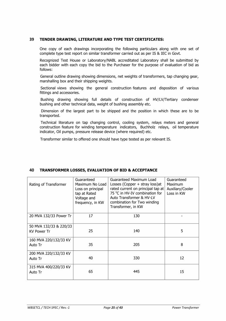
40 TRANSFORMER LOSSES, EVALUATION OF BID & ACCEPTANCE
Rating of Transformer
Guaranteed
Maximum No Load Loss on principal tap at Rated Voltage and frequency, in KW
Guaranteed Maximum Load Losses (Copper + stray loss)at rated current on principal tap at 75 oC in HV-IV combination for Auto Transformer & HV-LV combination for Two winding Transformer, in KW
Guaranteed
Maximum Auxiliary/Cooler Loss in KW
20 MVA 132/33 Power Tr 17 130 -
50 MVA 132/33 & 220/33
KV Power Tr
25
140
5
160 MVA 220/132/33 KV
Auto Tr
35
205
8
200 MVA 220/132/33 KV
Auto Tr
40
330
12
315 MVA 400/220/33 KV
Auto Tr
65
445
15
WBSETCL / TECH SPEC / Rev.-1 Page 26 of 43 Power Transformer
a) The Transformers are to be designed with maximum permissible losses as indicated above.
b) The bidder must clearly specify that the offered losses are "Maximum"(including IS/IEC tolerance) and no further positive tolerance as per IS/IEC shall be applicable on the
offered values during evaluation as well as during testing of transformer.
c) Bids offering with losses beyond the maximum limits mentioned above shall be treated as non-responsive and rejected.
d) Loss Capitalization shall be done with the accepted bids with loss values within specified limit . For the purpose of evaluation of bids, the capitalized cost of iron loss, load loss
and auxiliary loss (KW) shall be added to the quoted price of the transformer at the following rates:
i) Capitalized value of No Load loss per KW – Rs. 4,95,943/-
ii) Capitalized value of load loss per KW – Rs. 2,02,345/-
iii) Capitalized value of Auxiliary loss per KW – Rs. 1,98,377/-
e) However once a bidder becomes successful on the basis of loss capitalization with certain
declared loss value, they have to strictly achieve the same loss value during the course of
testing of transformers, offered for supply. No tolerance as per IS/IEC will be applicable.
f) If they fail to do so, the offered transformer will be rejected and only replaced
transformer with declared loss value will be accepted.
g) In this process, the delay so occurred will be on the vendor's account.
h) If the vendor fails to achieve the declared loss during second time, the contract will be terminated at the vendor's risk and cost.
41 STAGE INSPECTION:
Stage inspection will be carried out by the customer on Core, Coil & Tank during the
manufacturing stages of the transformer. The manufacturer will have to call for the stage inspection and shall arrange the inspection at manufacturer’s premises or manufacturer’s
bidders premises free of cost. Stage inspection will be carried out on 1 (one) number
Transformer against an offer of minimum 50% of the ordered quantity as mentioned in delivery schedule. On the basis of satisfactory Stage Inspection, manufacturer will proceed
further. The following stage inspection shall be carried in one inspection. Prior to stage inspection following documents shall have to be submitted by
manufacturer for verification:
1) Document related to prime core, procurement establishing traceability vide relevant Cl.
of Technical Specification of Power Transformer.
2) Documents for coil establishing traceability.
Following tests have to be carried out in stage inspection.
I. On Core
1) Flux density checking of assembled core (without having any insulating tape etc. rapped around the core) vis-à-vis measurement of step thickness, lamination width etc.
2) Window height, leg center dimension, core diameter of assembled core.
3) Physical verification of core in respect of lamination thickness, bend, camber and waviness etc.
WBSETCL / TECH SPEC / Rev.-1 Page 27 of 43 Power Transformer
4) Carlite test, Watt loss and ageing test on the sample of prime core. (Core sample shall be selected during stage inspection and sent to any NABL accredited laboratory for tests
under Sl.No. 4)
5) Loss measurement of Prime core (Loss/Kg).
6) 2KV test between core and Yoke clamps.
II. On Coil
1) Physical verification of HV, IV and LV wound coil for 160MVA,200 MVA and 315MVA Power Transformer (without any outer insulation).
2) Measurement of resistance of each finished coil (HV, IV & LV).
3) Measurement and current density calculation of each winding.
4) Copper purity test (after cutting from finished coil offered for inspection).
Calibration Certificates of all measuring instrument to be used during stage and final
inspection shall be produced and that will be in conformity to our relevant Clauses of GCC/Technical Specification.
III. On Tank
1) Physical inspection & Dimension Checking of Main Tank
2) Vacuum Withstand Test on the Main Tank.
3) Pressure Withstand Test on the Main Tank.
4) Leakage Test of the main Tank.
42 TEST AT FACTORY AND TEST CERTIFICATES:
All Routine and Acceptance tests at manufacturer’s works shall be carried out in presence of
WBSETCL’s representative in compliance with IS: 2026/ IEC 60076 (as amended up-to- date) on the transformers. The entire cost of acceptance test, routine test and special test as
follows that are to be carried out as per relevant IS shall be treated as included in quoted price of transformer.
1. The Contractor shall offer the transformer for final testing with at least 15 (fifteen) days prior to the actual date when the tests will be carried out.
2. Internal test report of each transformer and test reports of prime core and coil from NABL accredited laboratory shall be submitted at least 7(seven) day prior to date of testing.
Offer for final test shall be accepted after receiving above documents.
3. After final testing 6 (six) copies of test reports of each transformer along with soft copy and soft copy of final drawing shall be submitted to the Chief Engineer, Engg. Deptt. prior to
issuance of formal MICC & DI letter. The following tests are to be carried out as a part of routine tests as per IS:2026 / IEC 60076
and as per our standard requirement:
i) Resistance of each winding at all taps (wherever applicable).
ii) Turns ratio for all sets of windings on each tap
iii) Polarity and phase vector relationship
iv) Measurement of No Load Loss and No Load Current at 90, 100 and 110 percent rated voltage.
v) Impedance voltage at normal, maximum and minimum tap for each pair of winding.
WBSETCL / TECH SPEC / Rev.-1 Page 28 of 43 Power Transformer
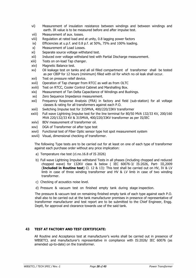
vi) Measurement of insulation resistance between windings and between windings and earth. IR value is to be measured before and after impulse test.
vii) Measurement of aux. losses.
viii) Regulation at rated load and at unity, 0.8 lagging power factors
ix) Efficiencies at u.p.f. and 0.8 p.f. at 50%, 75% and 100% loading.
x) Measurement of Load Losses.
xi) Separate source voltage withstand test.
xii) Induced over voltage withstand test with Partial Discharge measurement.
xiii) Tests on on-load Tap changer.
xiv) Magnetic Balance test.
xv) Oil leakage test on tanks and all oil filled compartment of transformer shall be tested
as per CBIP for 12 hours (minimum) filled with oil for which no oil leak shall occur.
xvi) Test on pressure relief device.
xvii) Operation of Tap changer from RTCC as well as from OLTC
xviii) Test on RTCC, Cooler Control Cabinet and Marshalling Box.
xix) Measurement of Tan Delta Capacitance of Windings and Bushings.
xx) Zero Sequence Impedance measurement.
xxi) Frequency Response Analysis (FRA) in factory and field (sub-station) for all voltage classes & rating for all transformers against each P.O.
xxii) Switching Impulse test for 315MVA, 400/220/33KV transformer
xxiii) Full wave Lightning Impulse test for the line terminal for 80/50 MVA 132/33 KV, 200/160
MVA 220/132/33 KV & 315MVA, 400/220/33KV transformer as per IS/IEC
xxiv) BDV measurement of transformer oil.
xxv) DGA of Transformer oil after type test
xxvi) Functional test of Fiber Optic sensor type hot spot measurement system
xxvii) Visual, dimensional checking of transformer.
The following Type tests are to be carried out for at least on one of each type of transformer
against each purchase order without any price implication:
a) Temperature rise test (cl.no.16.8 of IS 2026)
b) Full wave Lightning Impulse withstand Tests in all phases (including chopped and reduced chopped wave) for 132KV class & below ( IEC 60076-3/ IS:2026, Part- III,2009
(Included in Routine test) Cl. 12 & 13): This test shall be carried out on HV, IV & LV limb in case of three winding transformer and HV & LV limb in case of two winding
transformer.
c) Checking of acoustics noise level.
d) Pressure & vacuum test on finished empty tank during stage inspection.
The pressure & vacuum test on remaining finished empty tank of each type against each P.O.
shall also to be carried out at the tank manufacturer premises in presence of representative of transformer manufacturer and test report are to be submitted to the Chief Engineer, Engg.
Deptt, for approval and clearance towards use of the said tank.
43 TEST AT FACTORY AND TEST CERTIFICATE:
All Routine and Acceptance test at manufacturer’s works shall be carried out in presence of
WBSETCL and manufacturer’s representative in compliance with IS:2026/ IEC 60076 (as amended up-to-date) on the transformer.

WBSETCL / TECH SPEC / Rev.-1 Page 29 of 43 Power Transformer
44 TEST ON ASSOCIATED EQUIPMENT:
Porcelain Bushings, Windings Temperature Indicating Devices. Dial Thermometers, Buchholz Relays, Auxiliary Meters, Motor Starting Contactors, Control devices, Insulating oil and other
associated equipment covered by the contract shall be certified by the contractor to have been tested in accordance with the relevant IS specification by the manufacturer. The
contractor shall furnish a certificate of compliance of the relevant tests, for all auxiliary
apparatus. Six certified copies of the aforesaid test reports shall have to be furnished.
45 TOLERENCES
As per the clause of the IS 2026/ IEC 60076 tolerances will be applicable to certain
guaranteed values as depicted in the following tables:
SL Item Tolerance
1 Voltage ratio at no load on principal tapping for a specified first pair of windings
The lower of the following values:
a) ±0.5 % of declared ratio
b) ±1/10 of the actual percentage impedance
on the principal tapping
2 Voltage ratio on other tapings, same pair To be agreed, but not less than the lesser of
the values in a) and b) above
3 Voltage ratio for further pairs To be agreed, but not less than the lesser of
the values in a) and b) above
4 Short-circuit impedance for:
– a separate-winding transformer with two
windings, or
– a specified first pair of separate
windings in a multi-winding transformer
a) principal tapping
b) any other tapping of the pair
When the impedance value is ≥10 % : ±7,5 %
of the declared value
When the impedance value is <10 % : ±10 % of the declared value
When the impedance value is ≥10 % : ±10 %
of the declared value
When the impedance value is <10 %: ±15 %
of the declared value
5 Short-circuit impedance for:
– an auto-connected pair of winding, or
– a specified second pair of separate
windings in a multi-winding transformer
a) principal tapping
b) any other tapping of the pair
c) further pairs of windings
±10 % of the declared value
±15 % of the declared value for that tapping
To be agreed, but ≥15 %
6 No-load current +30 % of the declared value
WBSETCL / TECH SPEC / Rev.-1 Page 30 of 43 Power Transformer
NOTE - For certain auto-transformers and booster transformers the smallness of their
impedance justifies more liberal tolerance. Transformers having large tapping ranges,
particularly if the range is asymmetrical, may also require special consideration. On the
other hand, for example, when a transformer is to be combined with previously existing units,
it may be justified to specify and agree on narrower impedance tolerances. Matters of special
tolerances shall be brought to attention at the tender stage, and revised tolerances agreed
upon between manufacturer and purchaser.
NOTE - 'Declared value' should be understood as meaning the value declared by the
manufacturer.
46 DRYING OUT AT THE MANUFACTURER’S WORKS:
All the Tests shall be conducted after complete Drying out at the works. The transformer shall be despatched complete after being dried out under vacuum and filed with inert gas, ready to
be put into commission, without further drying out at site.
47 SUPERVISION OF ERECTION, TESTING & COMMISSIONING:
The MANUFACTURER shall arrange for the services of their Supervisor/Engineer from the manufacturer during erection, testing and commissioning of the equipment at sites at free
of cost as many time as required by WBSETCL.
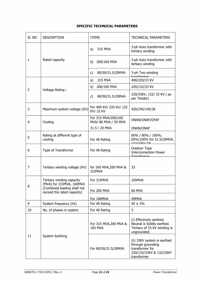
WBSETCL / TECH SPEC / Rev.-1 Page 31 of 43 Power Transformer
SPECIFIC TECHNICAL PARAMETERS
Sl. NO DESCRIPTION ITEMS TECHNICAL PARAMETERS
1
Rated capacity
a) 315 MVA 3-ph Auto transformer with
tertiary winding
b) 200/160 MVA
3-ph Auto transformer with
tertiary winding
c) 80/50/31.5/20MVA 3-ph Two winding
transformer
2
Voltage Rating :
a) 315 MVA 400/220/33 KV
b) 200/160 MVA 220/132/33 KV
c) 80/50/31.5/20MVA
220/33KV, 132/ 33 KV ( as
per Tender)
3
Maximum system voltage (KV)
For 400 KV/ 220 KV/ 132 KV/ 33 KV
420/245/145/36
4
Cooling
For 315 MVA/200/160
MVA/ 80 MVA / 50 MVA
31.5 / 20 MVA
ONAN/ONAF/OFAF
ONAN/ONAF
5
Rating at different type of
cooling
For All Rating
60% / 80% / 100%;
65%/100% for 31.5/20MVA,
132/33KV TR. 6
Type of Transformer
For All Rating
Outdoor Type Interconnection Power
Transformer
7
Tertiary winding voltage (KV)
for 160 MVA,200 MVA &
315MVA
33
8
Tertiary winding capacity (MVA) for 315MVA, 160MVA
(Combined loading shall not exceed the rated capacity)
For 315MVA 105MVA
For 200 MVA
60 MVA
For 160MVA
45MVA
9 System frequency (Hz) For All Rating 50 ± 3%
10 No. of phases in system For All Rating 3
11
System Earthing
For 315 MVA,200 MVA & 160 MVA
(i) Effectively earthed, Neutral is Solidly earthed.
Tertiary of 33 KV winding is
ungrounded.
For 80/50/31.5/20MVA
(ii) 33KV system is earthed
through grounding transformer for 220/132/33KV & 132/33KV transformer
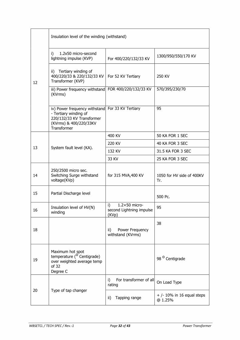
WBSETCL / TECH SPEC / Rev.-1 Page 32 of 43 Power Transformer
12
Insulation level of the winding (withstand)
i) 1.2x50 micro-second
lightning impulse (KVP)
For 400/220/132/33 KV
1300/950/550/170 KV
ii) Tertiary winding of
400/220/33 & 220/132/33 KV Transformer (KVP)
For 52 KV Tertiary
250 KV
iii) Power frequency withstand
(KVrms)
FOR 400/220/132/33 KV 570/395/230/70
iv) Power frequency withstand - Tertiary winding of
220/132/33 KV Transformer (KVrms) & 400/220/33KV
Transformer
For 33 KV Tertiary 95
13
System fault level (KA).
400 KV 50 KA FOR 1 SEC
220 KV 40 KA FOR 3 SEC
132 KV 31.5 KA FOR 3 SEC
33 KV 25 KA FOR 3 SEC
14
250/2500 micro sec.
Switching Surge withstand voltage(KVp)
for 315 MVA,400 KV
1050 for HV side of 400KV
Tr.
15
Partial Discharge level
500 Pc.
16
Insulation level of HV(N) winding
i) 1.2×50 micro-
second Lightning impulse
(KVp)
95
18
ii) Power Frequency withstand (KVrms)
38
19
Maximum hot spot
temperature (o
Centigrade)
over weighted average temp
of 32
Degree C
98 o
Centigrade
20
Type of tap changer
i) For transformer of all
rating
On Load Type
ii) Tapping range
+ /- 10% in 16 equal steps
@ 1.25%
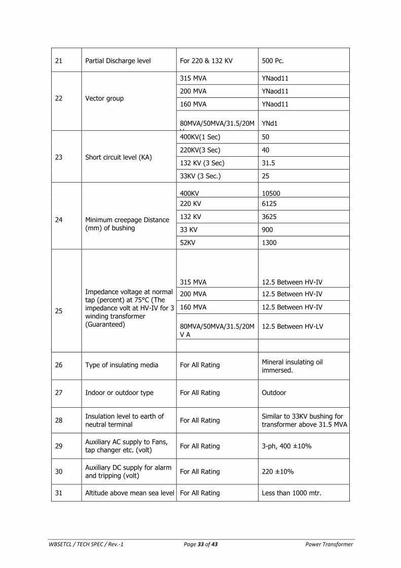
WBSETCL / TECH SPEC / Rev.-1 Page 33 of 43 Power Transformer
21
Partial Discharge level
For 220 & 132 KV
500 Pc.
22
Vector group
315 MVA YNaod11
200 MVA YNaod11
160 MVA YNaod11
80MVA/50MVA/31.5/20M
V
YNd1
23
Short circuit level (KA)
400KV(1 Sec) 50
220KV(3 Sec) 40
132 KV (3 Sec) 31.5
33KV (3 Sec.) 25
24
Minimum creepage Distance
(mm) of bushing
400KV
10500
220 KV 6125
132 KV 3625
33 KV 900
52KV 1300
25
Impedance voltage at normal tap (percent) at 75°C (The
impedance volt at HV-IV for 3
winding transformer (Guaranteed)
315 MVA
12.5 Between HV-IV
200 MVA 12.5 Between HV-IV
160 MVA 12.5 Between HV-IV
80MVA/50MVA/31.5/20M
V A
12.5 Between HV-LV
26
Type of insulating media
For All Rating Mineral insulating oil
immersed.
27
Indoor or outdoor type
For All Rating
Outdoor
28
Insulation level to earth of
neutral terminal
For All Rating
Similar to 33KV bushing for
transformer above 31.5 MVA .
29
Auxiliary AC supply to Fans, tap changer etc. (volt)
For All Rating
3-ph, 400 ±10%
30
Auxiliary DC supply for alarm and tripping (volt)
For All Rating
220 ±10%
31 Altitude above mean sea level For All Rating Less than 1000 mtr.
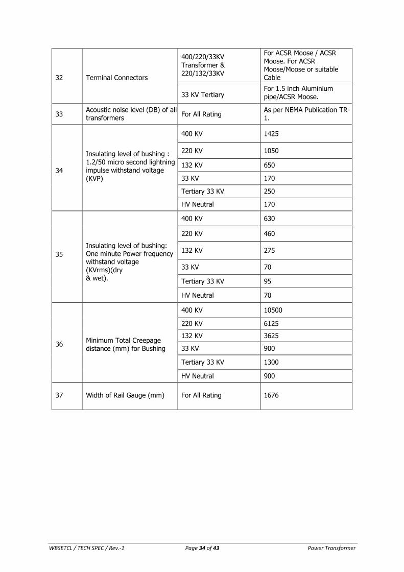
WBSETCL / TECH SPEC / Rev.-1 Page 34 of 43 Power Transformer
32
Terminal Connectors
400/220/33KV
Transformer &
220/132/33KV
For ACSR Moose / ACSR
Moose. For ACSR Moose/Moose or suitable
Cable
33 KV Tertiary
For 1.5 inch Aluminium
pipe/ACSR Moose.
33 Acoustic noise level (DB) of all transformers
For All Rating As per NEMA Publication TR- 1.
34
Insulating level of bushing :
1.2/50 micro second lightning impulse withstand voltage
(KVP)
400 KV 1425
220 KV 1050
132 KV 650
33 KV 170
Tertiary 33 KV 250
HV Neutral 170
35
Insulating level of bushing: One minute Power frequency withstand voltage (KVrms)(dry
& wet).
400 KV 630
220 KV 460
132 KV 275
33 KV 70
Tertiary 33 KV 95
HV Neutral 70
36
Minimum Total Creepage distance (mm) for Bushing
400 KV 10500
220 KV 6125
132 KV 3625
33 KV 900
Tertiary 33 KV 1300
HV Neutral 900
37
Width of Rail Gauge (mm)
For All Rating
1676
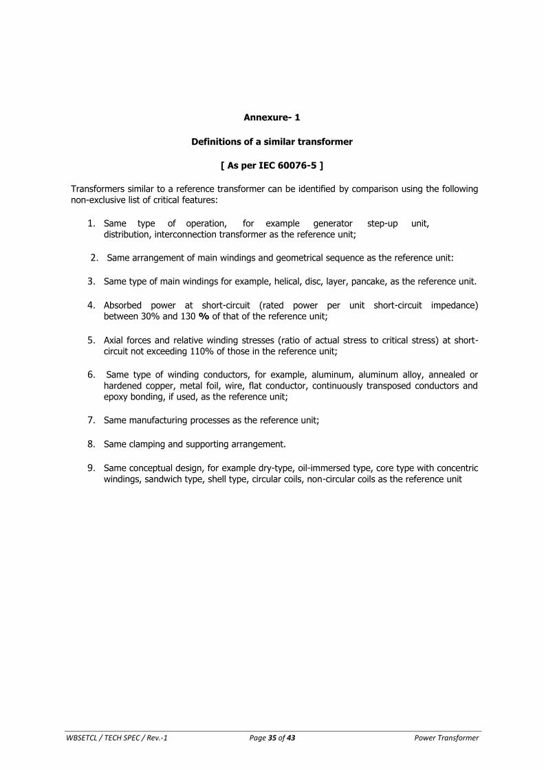
WBSETCL / TECH SPEC / Rev.-1 Page 35 of 43 Power Transformer
Annexure- 1
Definitions of a similar transformer
[ As per IEC 60076-5 ]
Transformers similar to a reference transformer can be identified by comparison using the following
non-exclusive list of critical features:
1. Same type of operation, for example generator step-up unit, distribution, interconnection transformer as the reference unit;
2. Same arrangement of main windings and geometrical sequence as the reference unit:
3. Same type of main windings for example, helical, disc, layer, pancake, as the reference unit.
4. Absorbed power at short-circuit (rated power per unit short-circuit impedance) between 30% and 130 % of that of the reference unit;
5. Axial forces and relative winding stresses (ratio of actual stress to critical stress) at short-circuit not exceeding 110% of those in the reference unit;
6. Same type of winding conductors, for example, aluminum, aluminum alloy, annealed or
hardened copper, metal foil, wire, flat conductor, continuously transposed conductors and epoxy bonding, if used, as the reference unit;
7. Same manufacturing processes as the reference unit;
8. Same clamping and supporting arrangement.
9. Same conceptual design, for example dry-type, oil-immersed type, core type with concentric
windings, sandwich type, shell type, circular coils, non-circular coils as the reference unit
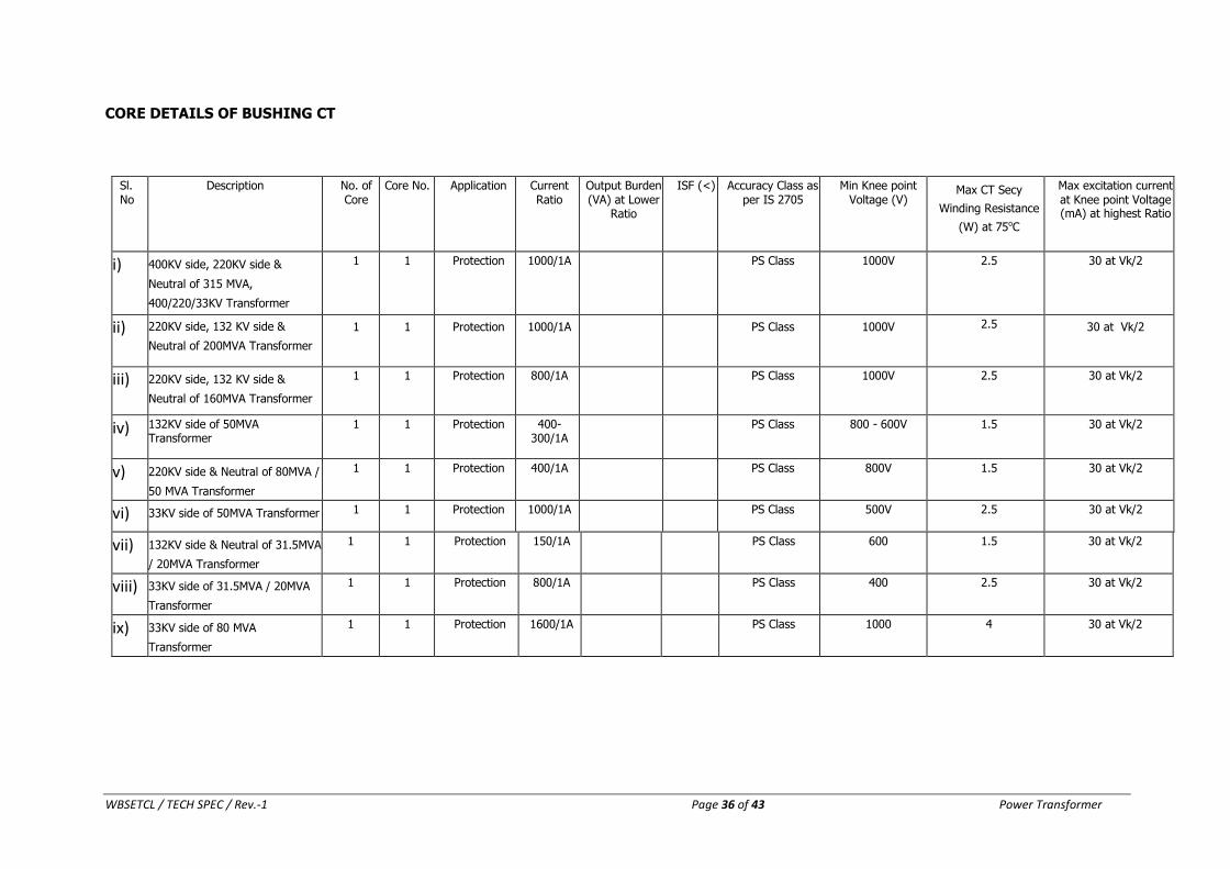
WBSETCL / TECH SPEC / Rev.-1 Page 36 of 43 Power Transformer
CORE DETAILS OF BUSHING CT
Sl. No
Description No. of Core
Core No. Application Current Ratio
Output Burden (VA) at Lower
Ratio
ISF (<) Accuracy Class as per IS 2705
Min Knee point Voltage (V)
Max CT Secy
Winding Resistance
(W) at 75oC
Max excitation current at Knee point Voltage (mA) at highest Ratio
i) 400KV side, 220KV side &
Neutral of 315 MVA,
400/220/33KV Transformer
1 1 Protection 1000/1A PS Class 1000V 2.5 30 at Vk/2
ii) 220KV side, 132 KV side &
Neutral of 200MVA Transformer
1 1 Protection 1000/1A PS Class 1000V 2.5 30 at Vk/2
iii) 220KV side, 132 KV side &
Neutral of 160MVA Transformer
1 1 Protection 800/1A PS Class 1000V 2.5 30 at Vk/2
iv) 132KV side of 50MVA Transformer
1 1 Protection 400-300/1A
PS Class 800 - 600V 1.5 30 at Vk/2
v) 220KV side & Neutral of 80MVA /
50 MVA Transformer
1 1 Protection 400/1A PS Class 800V 1.5 30 at Vk/2
vi) 33KV side of 50MVA Transformer 1 1 Protection 1000/1A PS Class 500V 2.5 30 at Vk/2
vii) 132KV side & Neutral of 31.5MVA
/ 20MVA Transformer
1 1 Protection 150/1A PS Class 600 1.5 30 at Vk/2
viii) 33KV side of 31.5MVA / 20MVA
Transformer
1 1 Protection 800/1A PS Class 400 2.5 30 at Vk/2
ix) 33KV side of 80 MVA
Transformer
1 1 Protection 1600/1A PS Class 1000 4 30 at Vk/2

WBSETCL / TECH SPEC / Rev.-1 Page 37 of 43 Power Transformer
Guaranteed Technical Particulars (GTP) of Offered Transformer
( To be submitted separately for separate MVA capacity of Transformer in case of common
Tender)
SL DESCRIPTION SUBMISSION
1 General Data of Bidder
a Name & Address of Company
b Country of Origin
c
Business Type of Company (eg.
Manufacturer/ Supplier / Transporter etc.)
2
General Data of Transformer
a
Conforming Applicable Standards
(including Bushing & other)
b
Conceptual Design of Transformer
( e.g. Outdoor oil immersed core type
/Indoor dry core type/etc)
c
Type of Operation of the Transformer
(e.g. Interconnection / Distribution/ Generator step-up)
* Interconnection means used in
Transmission Grid SS
d Rated Frequency (in Hz)
e Number of Phase
f
Rated MVA Capacity Of the Transformer
(ONAN/ ONAF/OFAF)
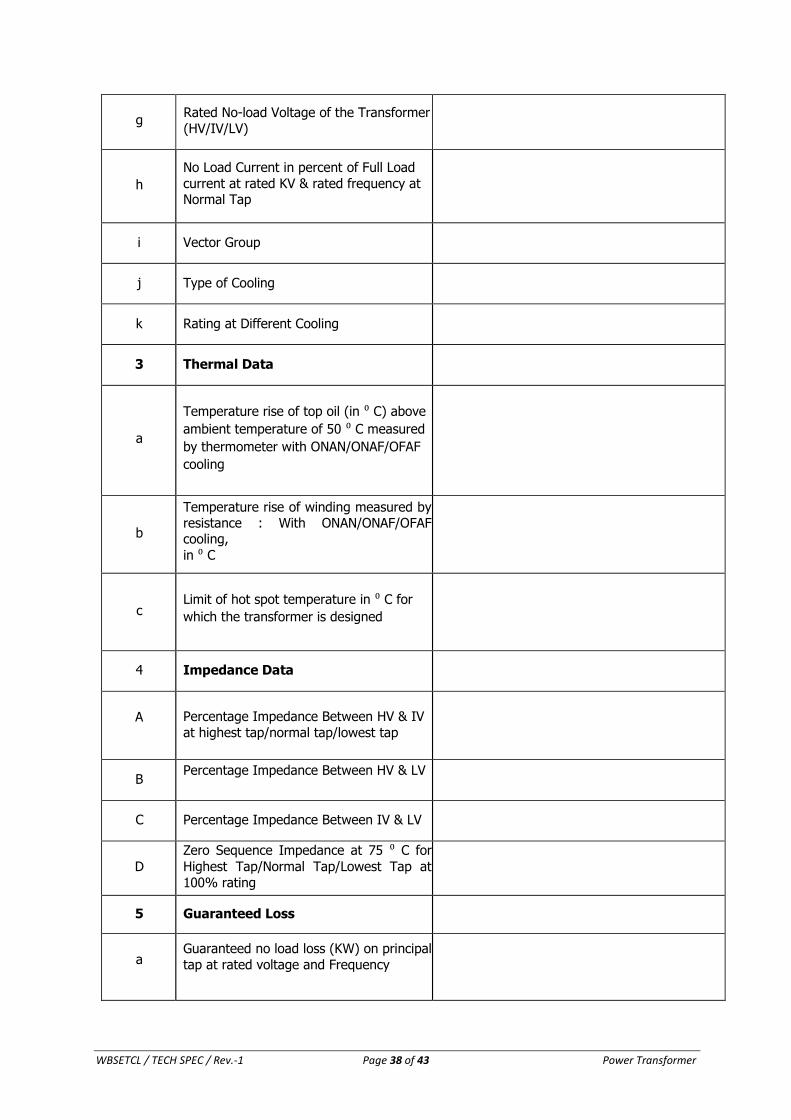
WBSETCL / TECH SPEC / Rev.-1 Page 38 of 43 Power Transformer
g Rated No-load Voltage of the Transformer
(HV/IV/LV)
h
No Load Current in percent of Full Load
current at rated KV & rated frequency at Normal Tap
i Vector Group
j Type of Cooling
k Rating at Different Cooling
3 Thermal Data
a
Temperature rise of top oil (in ⁰ C) above
ambient temperature of 50 ⁰ C measured
by thermometer with ONAN/ONAF/OFAF
cooling
b
Temperature rise of winding measured by resistance : With ONAN/ONAF/OFAF cooling,
in ⁰ C
c
Limit of hot spot temperature in ⁰ C for
which the transformer is designed
4 Impedance Data
A
Percentage Impedance Between HV & IV
at highest tap/normal tap/lowest tap
B Percentage Impedance Between HV & LV
C Percentage Impedance Between IV & LV
D
Zero Sequence Impedance at 75 ⁰ C for
Highest Tap/Normal Tap/Lowest Tap at
100% rating
5 Guaranteed Loss
a
Guaranteed no load loss (KW) on principal
tap at rated voltage and Frequency
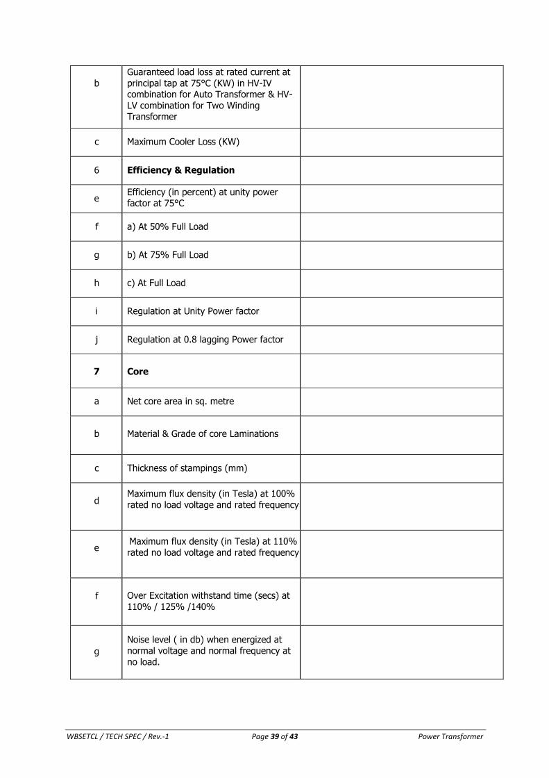
WBSETCL / TECH SPEC / Rev.-1 Page 39 of 43 Power Transformer
b
Guaranteed load loss at rated current at
principal tap at 75°C (KW) in HV-IV combination for Auto Transformer & HV-
LV combination for Two Winding Transformer
c Maximum Cooler Loss (KW)
6 Efficiency & Regulation
e Efficiency (in percent) at unity power factor at 75°C
f a) At 50% Full Load
g b) At 75% Full Load
h c) At Full Load
i Regulation at Unity Power factor
j Regulation at 0.8 lagging Power factor
7
Core
a Net core area in sq. metre
b
Material & Grade of core Laminations
c Thickness of stampings (mm)
d
Maximum flux density (in Tesla) at 100%
rated no load voltage and rated frequency
e
Maximum flux density (in Tesla) at 110%
rated no load voltage and rated frequency
f
Over Excitation withstand time (secs) at
110% / 125% /140%
g
Noise level ( in db) when energized at
normal voltage and normal frequency at
no load.
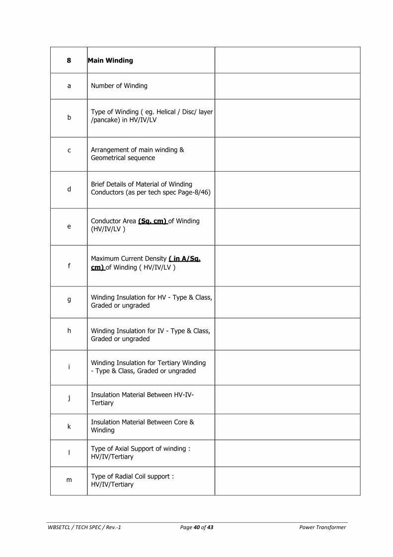
WBSETCL / TECH SPEC / Rev.-1 Page 40 of 43 Power Transformer
8 Main Winding
a
Number of Winding
b
Type of Winding ( eg. Helical / Disc/ layer
/pancake) in HV/IV/LV
c
Arrangement of main winding &
Geometrical sequence
d
Brief Details of Material of Winding
Conductors (as per tech spec Page-8/46)
e
Conductor Area (Sq. cm) of Winding
(HV/IV/LV )
f
Maximum Current Density ( in A/Sq.
cm) of Winding ( HV/IV/LV )
g Winding Insulation for HV - Type & Class,
Graded or ungraded
h
Winding Insulation for IV - Type & Class, Graded or ungraded
i
Winding Insulation for Tertiary Winding
- Type & Class, Graded or ungraded
j Insulation Material Between HV-IV-
Tertiary
k
Insulation Material Between Core &
Winding
l
Type of Axial Support of winding :
HV/IV/Tertiary
m
Type of Radial Coil support :
HV/IV/Tertiary
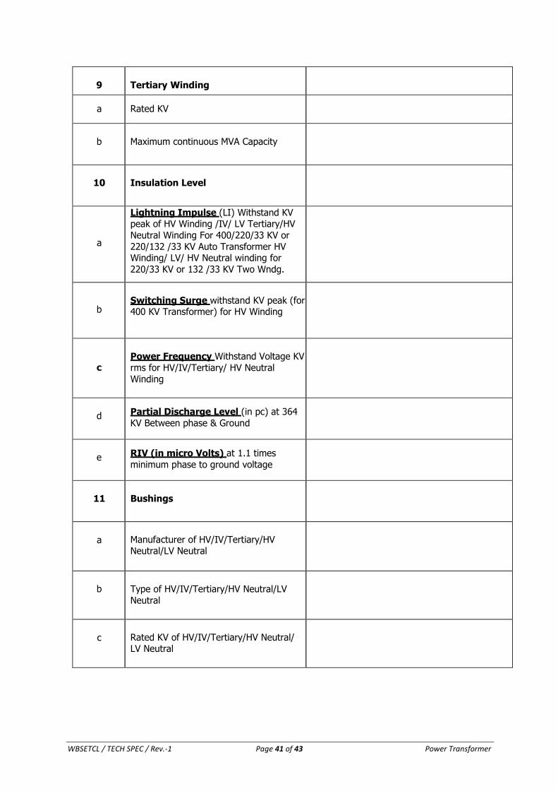
WBSETCL / TECH SPEC / Rev.-1 Page 41 of 43 Power Transformer
9
Tertiary Winding
a Rated KV
b
Maximum continuous MVA Capacity
10
Insulation Level
a
Lightning Impulse (LI) Withstand KV peak of HV Winding /IV/ LV Tertiary/HV
Neutral Winding For 400/220/33 KV or
220/132 /33 KV Auto Transformer HV Winding/ LV/ HV Neutral winding for
220/33 KV or 132 /33 KV Two Wndg.
b
Switching Surge withstand KV peak (for 400 KV Transformer) for HV Winding
c
Power Frequency Withstand Voltage KV
rms for HV/IV/Tertiary/ HV Neutral
Winding
d Partial Discharge Level (in pc) at 364
KV Between phase & Ground
e RIV (in micro Volts) at 1.1 times
minimum phase to ground voltage
11
Bushings
a
Manufacturer of HV/IV/Tertiary/HV Neutral/LV Neutral
b
Type of HV/IV/Tertiary/HV Neutral/LV
Neutral
c
Rated KV of HV/IV/Tertiary/HV Neutral/ LV Neutral
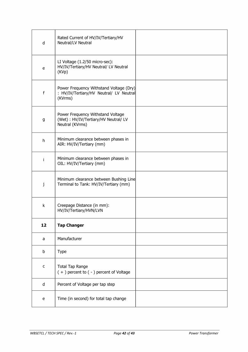
WBSETCL / TECH SPEC / Rev.-1 Page 42 of 43 Power Transformer
d
Rated Current of HV/IV/Tertiary/HV Neutral/LV Neutral
e
LI Voltage (1.2/50 micro-sec):
HV/IV/Tertiary/HV Neutral/ LV Neutral (KVp)
f
Power Frequency Withstand Voltage (Dry) : HV/IV/Tertiary/HV Neutral/ LV Neutral
(KVrms)
g
Power Frequency Withstand Voltage
(Wet) : HV/IV/Tertiary/HV Neutral/ LV Neutral (KVrms)
h Minimum clearance between phases in
AIR: HV/IV/Tertiary (mm)
i Minimum clearance between phases in
OIL: HV/IV/Tertiary (mm)
j
Minimum clearance between Bushing Line Terminal to Tank: HV/IV/Tertiary (mm)
k
Creepage Distance (in mm):
HV/IV/Tertiary/HVN/LVN
12 Tap Changer
a Manufacturer
b Type
c
Total Tap Range
( + ) percent to ( - ) percent of Voltage
d Percent of Voltage per tap step
e
Time (in second) for total tap change
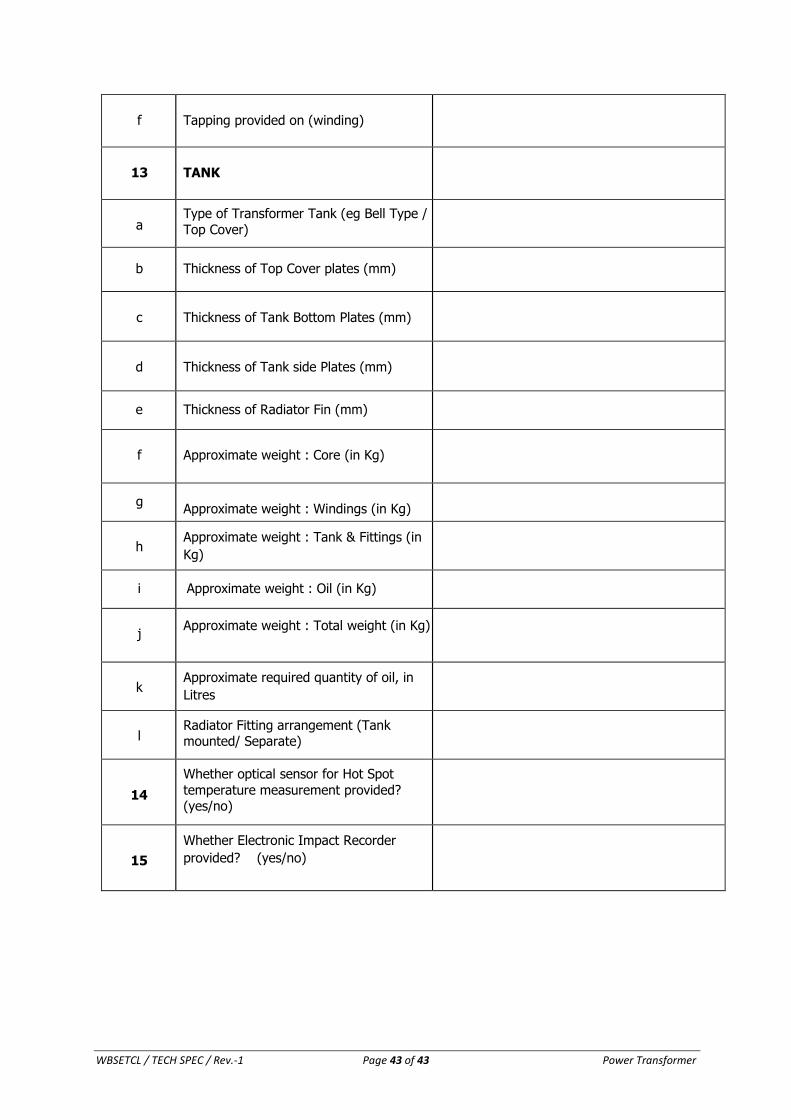
WBSETCL / TECH SPEC / Rev.-1 Page 43 of 43 Power Transformer
f
Tapping provided on (winding)
13
TANK
a Type of Transformer Tank (eg Bell Type /
Top Cover)
b Thickness of Top Cover plates (mm)
c
Thickness of Tank Bottom Plates (mm)
d
Thickness of Tank side Plates (mm)
e Thickness of Radiator Fin (mm)
f
Approximate weight : Core (in Kg)
g
Approximate weight : Windings (in Kg)
h
Approximate weight : Tank & Fittings (in
Kg)
i Approximate weight : Oil (in Kg)
j Approximate weight : Total weight (in Kg)
k
Approximate required quantity of oil, in
Litres
l
Radiator Fitting arrangement (Tank mounted/ Separate)
14
Whether optical sensor for Hot Spot
temperature measurement provided? (yes/no)
15
Whether Electronic Impact Recorder
provided? (yes/no)