MSCS Clustering Implementation Mylex eXtremeRAID 1100 PCI-to-Ultra2 SCSI RAID Controllers.
Power Systems
SAS RAID controllers for AIX
���


Power Systems
SAS RAID controllers for AIX
���

NoteBefore using this information and the product it supports, read the information in “Notices,” onpage 137, “Safety notices” on page vii, the IBM Systems Safety Notices manual, G229-9054, and theIBM Environmental Notices and User Guide, Z125–5823.
This edition applies to IBM Power Systems™ servers that contain the POWER6™ processor and to all associatedmodels.
© Copyright International Business Machines Corporation 2007, 2009.US Government Users Restricted Rights – Use, duplication or disclosure restricted by GSA ADP Schedule Contractwith IBM Corp.

Contents
Safety notices . . . . . . . . . . . . . . . . . . . . . . . . . . . . . . . . vii
Chapter 1. SAS RAID controllers for AIX overview . . . . . . . . . . . . . . . . . 1Feature comparison of SAS RAID cards . . . . . . . . . . . . . . . . . . . . . . . . . . 1
PCI-X SAS RAID card comparison . . . . . . . . . . . . . . . . . . . . . . . . . . . 1PCIe SAS RAID card comparison . . . . . . . . . . . . . . . . . . . . . . . . . . . 5
SAS architecture . . . . . . . . . . . . . . . . . . . . . . . . . . . . . . . . . . 8Disk arrays . . . . . . . . . . . . . . . . . . . . . . . . . . . . . . . . . . . 10
Supported RAID levels . . . . . . . . . . . . . . . . . . . . . . . . . . . . . . 12RAID 0 . . . . . . . . . . . . . . . . . . . . . . . . . . . . . . . . . . . 12RAID 5 . . . . . . . . . . . . . . . . . . . . . . . . . . . . . . . . . . . 13RAID 6 . . . . . . . . . . . . . . . . . . . . . . . . . . . . . . . . . . . 13RAID 10 . . . . . . . . . . . . . . . . . . . . . . . . . . . . . . . . . . 14
Disk array capacities . . . . . . . . . . . . . . . . . . . . . . . . . . . . . . . 15RAID level summary . . . . . . . . . . . . . . . . . . . . . . . . . . . . . . . 15Stripe-unit size . . . . . . . . . . . . . . . . . . . . . . . . . . . . . . . . . 16Valid states for hdisks and pdisks . . . . . . . . . . . . . . . . . . . . . . . . . . . 16
States for disk arrays (hdisks) . . . . . . . . . . . . . . . . . . . . . . . . . . . 16States for physical disks (pdisks) . . . . . . . . . . . . . . . . . . . . . . . . . . 17pdisk descriptions . . . . . . . . . . . . . . . . . . . . . . . . . . . . . . . 17
Auxiliary write cache . . . . . . . . . . . . . . . . . . . . . . . . . . . . . . . 17Auxiliary write cache adapter . . . . . . . . . . . . . . . . . . . . . . . . . . . 17Installing the auxiliary write cache . . . . . . . . . . . . . . . . . . . . . . . . . 19Viewing link status information . . . . . . . . . . . . . . . . . . . . . . . . . . 20
Chapter 2. Controller software . . . . . . . . . . . . . . . . . . . . . . . . . 23Controller software verification . . . . . . . . . . . . . . . . . . . . . . . . . . . . . 23
Chapter 3. Common controller and disk array management tasks . . . . . . . . . . 25Using the Disk Array Manager . . . . . . . . . . . . . . . . . . . . . . . . . . . . . 25Preparing disks for use in SAS disk arrays . . . . . . . . . . . . . . . . . . . . . . . . . 26Creating a disk array . . . . . . . . . . . . . . . . . . . . . . . . . . . . . . . . 26Migrating an existing disk array to a new RAID level . . . . . . . . . . . . . . . . . . . . . 27Viewing the disk array configuration . . . . . . . . . . . . . . . . . . . . . . . . . . . 29Deleting a disk array . . . . . . . . . . . . . . . . . . . . . . . . . . . . . . . . 30Adding disks to an existing disk array . . . . . . . . . . . . . . . . . . . . . . . . . . 31Using hot spare disks . . . . . . . . . . . . . . . . . . . . . . . . . . . . . . . . 32
Creating hot spare disks . . . . . . . . . . . . . . . . . . . . . . . . . . . . . . 32Deleting hot spare disks . . . . . . . . . . . . . . . . . . . . . . . . . . . . . . 32
Viewing IBM SAS disk array settings . . . . . . . . . . . . . . . . . . . . . . . . . . . 32Viewing IBM SAS pdisk settings . . . . . . . . . . . . . . . . . . . . . . . . . . . . 33Viewing pdisk vital product data . . . . . . . . . . . . . . . . . . . . . . . . . . . . 34Viewing controller SAS addresses . . . . . . . . . . . . . . . . . . . . . . . . . . . . 34Controller SAS address attributes . . . . . . . . . . . . . . . . . . . . . . . . . . . . 34AIX command-line interface . . . . . . . . . . . . . . . . . . . . . . . . . . . . . . 35
Chapter 4. Multi-initiator and high availability . . . . . . . . . . . . . . . . . . . 37Possible HA configurations . . . . . . . . . . . . . . . . . . . . . . . . . . . . . . 37Controller functions . . . . . . . . . . . . . . . . . . . . . . . . . . . . . . . . 39Controller function attributes . . . . . . . . . . . . . . . . . . . . . . . . . . . . . 41Viewing HA controller attributes . . . . . . . . . . . . . . . . . . . . . . . . . . . . 42HA cabling considerations . . . . . . . . . . . . . . . . . . . . . . . . . . . . . . 42HA performance considerations . . . . . . . . . . . . . . . . . . . . . . . . . . . . 43HA access optimization . . . . . . . . . . . . . . . . . . . . . . . . . . . . . . . 43
© Copyright IBM Corp. 2007, 2009 iii

HA access characteristics within List SAS Disk Array Configuration . . . . . . . . . . . . . . . . 46Configuration and serviceability considerations for HA RAID configurations . . . . . . . . . . . . . 47Installing high availability . . . . . . . . . . . . . . . . . . . . . . . . . . . . . . 48
Installing an HA single-system RAID configuration . . . . . . . . . . . . . . . . . . . . . 48Installing an HA two-system RAID configuration. . . . . . . . . . . . . . . . . . . . . . 51Functions requiring special attention in an HA two-system RAID configuration . . . . . . . . . . . 55Installing an HA two-system JBOD configuration . . . . . . . . . . . . . . . . . . . . . . 55
Chapter 5. SAS RAID controller maintenance . . . . . . . . . . . . . . . . . . . 59Updating the SAS RAID controller microcode . . . . . . . . . . . . . . . . . . . . . . . . 59Changing pdisks to hdisks . . . . . . . . . . . . . . . . . . . . . . . . . . . . . . 60Rechargeable battery maintenance . . . . . . . . . . . . . . . . . . . . . . . . . . . . 60
Displaying rechargeable battery information . . . . . . . . . . . . . . . . . . . . . . . 60Error state . . . . . . . . . . . . . . . . . . . . . . . . . . . . . . . . . . . 62Forcing a rechargeable battery error . . . . . . . . . . . . . . . . . . . . . . . . . . 62
Replacing a battery pack . . . . . . . . . . . . . . . . . . . . . . . . . . . . . . . 63Replacing a 572B nonconcurrent maintainable battery pack . . . . . . . . . . . . . . . . . . 63Replacing a 57B7 concurrent maintainable battery pack. . . . . . . . . . . . . . . . . . . . 65Replacing a 574E concurrent maintainable battery pack. . . . . . . . . . . . . . . . . . . . 67Replacing a 572F/575C card set concurrent maintainable battery pack . . . . . . . . . . . . . . . 68
Separating the 572F/575C card set and moving the cache directory card . . . . . . . . . . . . . . . 69Replacing the cache directory card. . . . . . . . . . . . . . . . . . . . . . . . . . . . 73Replacing pdisks . . . . . . . . . . . . . . . . . . . . . . . . . . . . . . . . . 75Viewing SAS fabric path information . . . . . . . . . . . . . . . . . . . . . . . . . . . 76Example: Using SAS fabric path information . . . . . . . . . . . . . . . . . . . . . . . . 77
Chapter 6. Problem determination and recovery . . . . . . . . . . . . . . . . . . 83SAS resource locations. . . . . . . . . . . . . . . . . . . . . . . . . . . . . . . . 83Showing physical resource attributes . . . . . . . . . . . . . . . . . . . . . . . . . . . 84Disk array problem identification . . . . . . . . . . . . . . . . . . . . . . . . . . . . 85Service request numbers . . . . . . . . . . . . . . . . . . . . . . . . . . . . . . . 86Controller maintenance analysis procedures . . . . . . . . . . . . . . . . . . . . . . . . 88
Examining the hardware error log . . . . . . . . . . . . . . . . . . . . . . . . . . . 88MAP 3100 . . . . . . . . . . . . . . . . . . . . . . . . . . . . . . . . . . . 89MAP 3110 . . . . . . . . . . . . . . . . . . . . . . . . . . . . . . . . . . . 89MAP 3111 . . . . . . . . . . . . . . . . . . . . . . . . . . . . . . . . . . . 91MAP 3112 . . . . . . . . . . . . . . . . . . . . . . . . . . . . . . . . . . . 92MAP 3113 . . . . . . . . . . . . . . . . . . . . . . . . . . . . . . . . . . . 94MAP 3120 . . . . . . . . . . . . . . . . . . . . . . . . . . . . . . . . . . . 96MAP 3121 . . . . . . . . . . . . . . . . . . . . . . . . . . . . . . . . . . . 99MAP 3130 . . . . . . . . . . . . . . . . . . . . . . . . . . . . . . . . . . . 99MAP 3131 . . . . . . . . . . . . . . . . . . . . . . . . . . . . . . . . . . 101MAP 3132 . . . . . . . . . . . . . . . . . . . . . . . . . . . . . . . . . . 105MAP 3133 . . . . . . . . . . . . . . . . . . . . . . . . . . . . . . . . . . 107MAP 3134 . . . . . . . . . . . . . . . . . . . . . . . . . . . . . . . . . . 107MAP 3135 . . . . . . . . . . . . . . . . . . . . . . . . . . . . . . . . . . 111MAP 3140 . . . . . . . . . . . . . . . . . . . . . . . . . . . . . . . . . . 111MAP 3141 . . . . . . . . . . . . . . . . . . . . . . . . . . . . . . . . . . 112MAP 3142 . . . . . . . . . . . . . . . . . . . . . . . . . . . . . . . . . . 113MAP 3143 . . . . . . . . . . . . . . . . . . . . . . . . . . . . . . . . . . 114MAP 3144 . . . . . . . . . . . . . . . . . . . . . . . . . . . . . . . . . . 115MAP 3145 . . . . . . . . . . . . . . . . . . . . . . . . . . . . . . . . . . 119MAP 3146 . . . . . . . . . . . . . . . . . . . . . . . . . . . . . . . . . . 120MAP 3147 . . . . . . . . . . . . . . . . . . . . . . . . . . . . . . . . . . 123MAP 3148 . . . . . . . . . . . . . . . . . . . . . . . . . . . . . . . . . . 124MAP 3149 . . . . . . . . . . . . . . . . . . . . . . . . . . . . . . . . . . 125MAP 3150 . . . . . . . . . . . . . . . . . . . . . . . . . . . . . . . . . . 125MAP 3152 . . . . . . . . . . . . . . . . . . . . . . . . . . . . . . . . . . 128MAP 3153 . . . . . . . . . . . . . . . . . . . . . . . . . . . . . . . . . . 131MAP 3190 . . . . . . . . . . . . . . . . . . . . . . . . . . . . . . . . . . 134
iv

Finding a service request number from an existing AIX error log . . . . . . . . . . . . . . . . 135
Appendix. Notices . . . . . . . . . . . . . . . . . . . . . . . . . . . . . . 137Trademarks . . . . . . . . . . . . . . . . . . . . . . . . . . . . . . . . . . . 138Electronic emission notices . . . . . . . . . . . . . . . . . . . . . . . . . . . . . . 138
Class A Notices. . . . . . . . . . . . . . . . . . . . . . . . . . . . . . . . . 138Terms and conditions. . . . . . . . . . . . . . . . . . . . . . . . . . . . . . . . 142
Contents v

vi

Safety notices
Safety notices may be printed throughout this guide:v DANGER notices call attention to a situation that is potentially lethal or extremely hazardous to
people.v CAUTION notices call attention to a situation that is potentially hazardous to people because of some
existing condition.v Attention notices call attention to the possibility of damage to a program, device, system, or data.
World Trade safety information
Several countries require the safety information contained in product publications to be presented in theirnational languages. If this requirement applies to your country, a safety information booklet is includedin the publications package shipped with the product. The booklet contains the safety information inyour national language with references to the U.S. English source. Before using a U.S. English publicationto install, operate, or service this product, you must first become familiar with the related safetyinformation in the booklet. You should also refer to the booklet any time you do not clearly understandany safety information in the U.S. English publications.
German safety information
Das Produkt ist nicht für den Einsatz an Bildschirmarbeitsplätzen im Sinne § 2 derBildschirmarbeitsverordnung geeignet.
Laser safety information
IBM® servers can use I/O cards or features that are fiber-optic based and that utilize lasers or LEDs.
Laser compliance
All lasers are certified in the U.S. to conform to the requirements of DHHS 21 CFR Subchapter J for class1 laser products. Outside the U.S., they are certified to be in compliance with IEC 60825 as a class 1 laserproduct. Consult the label on each part for laser certification numbers and approval information.
CAUTION:This product might contain one or more of the following devices: CD-ROM drive, DVD-ROM drive,DVD-RAM drive, or laser module, which are Class 1 laser products. Note the following information:
v Do not remove the covers. Removing the covers of the laser product could result in exposure tohazardous laser radiation. There are no serviceable parts inside the device.
v Use of the controls or adjustments or performance of procedures other than those specified hereinmight result in hazardous radiation exposure.
(C026)
CAUTION:Data processing environments can contain equipment transmitting on system links with laser modulesthat operate at greater than Class 1 power levels. For this reason, never look into the end of an opticalfiber cable or open receptacle. (C027)
CAUTION:This product contains a Class 1M laser. Do not view directly with optical instruments. (C028)
© Copyright IBM Corp. 2007, 2009 vii

CAUTION:Some laser products contain an embedded Class 3A or Class 3B laser diode. Note the followinginformation: laser radiation when open. Do not stare into the beam, do not view directly with opticalinstruments, and avoid direct exposure to the beam. (C030)
Power and cabling information for NEBS (Network Equipment-Building System)GR-1089-CORE
The following comments apply to the IBM servers that have been designated as conforming to NEBS(Network Equipment-Building System) GR-1089-CORE:
The equipment is suitable for installation in the following:v Network telecommunications facilitiesv Locations where the NEC (National Electrical Code) applies
The intrabuilding ports of this equipment are suitable for connection to intrabuilding or unexposedwiring or cabling only. The intrabuilding ports of this equipment must not be metallically connected to theinterfaces that connect to the OSP (outside plant) or its wiring. These interfaces are designed for use asintrabuilding interfaces only (Type 2 or Type 4 ports as described in GR-1089-CORE) and require isolationfrom the exposed OSP cabling. The addition of primary protectors is not sufficient protection to connectthese interfaces metallically to OSP wiring.
Note: All Ethernet cables must be shielded and grounded at both ends.
The ac-powered system does not require the use of an external surge protection device (SPD).
The dc-powered system employs an isolated DC return (DC-I) design. The DC battery return terminalshall not be connected to the chassis or frame ground.
viii

Chapter 1. SAS RAID controllers for AIX overview
Find usage and maintenance information regarding controllers for the serial-attached SCSI (SAS)Redundant Array of Independent Disks (RAID) for the AIX® operating system. Use this information inconjunction with your specific system unit and operating system documentation. General information isintended for all users of this product. Service information is intended for a service representativespecifically trained on the system unit and subsystem being serviced.
The SAS RAID controllers for AIX have the following features:v PCI-X 266 system interface or PCI Express™ (PCIe) system interface.v Physical link (phy) speed of 3 Gbps SAS supporting transfer rates of 300 MB per second.v Supports SAS devices and non-disk Serial Advanced Technology Attachment (SATA) devices.v Optimized for SAS disk configurations that use dual paths through dual expanders for redundancy
and reliability.v Controller managed path redundancy and path switching for multiported SAS devices.v Embedded PowerPC® RISC Processor, hardware XOR DMA Engine, and hardware Finite Field
Multiplier (FFM) DMA Engine (for Redundant Array of Independent Disks (RAID) 6).v Some adapters support nonvolatile write cache.v Support for RAID 0, 5, 6, and 10 disk arrays.v Supports attachment of other devices such as non-RAID disks, tape, and optical devices.v RAID disk arrays and non-RAID devices supported as a bootable device.v Advanced RAID features:
– Hot spares for RAID 5, 6, and 10 disk arrays– Ability to increase the capacity of an existing RAID 5 or 6 disk array by adding disks– Background parity checking– Background data scrubbing– Disks formatted to 528 bytes per sector, providing cyclical redundancy checking (CRC) and logically
bad block checking– Optimized hardware for RAID 5 and 6 sequential write workloads– Optimized skip read/write disk support for transaction workloads
v Supports a maximum of 64 advanced function disks with a total device support maximum of 255 (thenumber of all physical SAS and SATA devices plus number of logical RAID disk arrays must be lessthan 255 per controller).
Feature comparison of SAS RAID cardsCompare the main features of PCI-X and PCI Express (PCIe) SAS RAID cards.
These tables provides a breakdown of the main features of the SAS RAID PCI-X and PCIe controllercards.
PCI-X SAS RAID card comparisonThis table compares the main features of PCI-X SAS RAID cards.
© Copyright IBM Corp. 2007, 2009 1

Table 1. PCI-X SAS RAID controller cards
CCIN (customcardidentificationnumber) 572A 572B 572C 572F / 575C 57B8
Description PCI-X 266 ExtDual-x4 3 Gb SASAdapter
PCI-X 266 ExtDual-x4 3 Gb SASRAID Adapter
PCI-X 266 Planar3 Gb SAS Adapter
PCI-X 266 ExtTri-x4 3 Gb SASRAID Adapter
PCI-X 266 Planar3 Gb SAS RAIDAdapter
Form factor Low profile 64-bitPCI-X
Long 64-bit PCI-X Planar integrated Long 64-bit PCI-X,double-wide cardset
Planar RAIDenablement
Adapter failingfunction codeLED value
2515 2517 2502 2519 / 251D 2505
Physical links 8 (two mini SAS4x connectors)
8 (two mini SAS4x connectors)
81 12 (bottom 3 miniSAS 4xconnectors) and 2(top mini SAS 4xconnector for HAonly)
81
RAID levelssupported
RAID 0, 54, 64, 10 RAID 0, 5, 6, 10 RAID 0 RAID 0, 5, 6, 10 RAID 0, 5, 6, 10
Write cache size 175 MB Up to 1.5 Gb(compressed)
175 MB
Read cache size Up to 1.6 Gb(compressed)
Cache batterypack technology
LiIon LiIon Not applicable2
Cache batterypack FFC
2D03 2D065 Not applicable2
Cache batteryconcurrentmaintenance
No No No Yes Not applicable2
Cache datapresent LED
No No No No No
Removablecache card
No Yes No No No
Auxiliary writecache (AWC)support
No No No Yes Yes
High availability(HA) twosystem RAID
Yes3 Yes No No No
HA two systemJBOD
Yes3 No No No No
HA singlesystem RAID
Yes3 Yes No No No
Requires HARAIDconfiguration
No Yes No No No
2

Table 1. PCI-X SAS RAID controller cards (continued)
CCIN (customcardidentificationnumber) 572A 572B 572C 572F / 575C 57B8
1 Some systems provide an external mini SAS 4x connector from the integrated backplane controller.2 The controller contains battery-backed cache, but the battery power is supplied by the 57B8 controller throughthe backplane connections.3 Multi-initiator and high availability is supported on the CCIN 572A adapter except for part numbers of either44V4266 or 44V4404 (feature code 5900).4 The write performance of RAID 5 and RAID 6 might be poor on adapters that do not provide write cache.Consider using an adapter that provides write cache when using RAID 5 or RAID 6.5The cache battery pack for both adapters is contained in a single battery FRU, which is physically located on the575C auxiliary cache card.
Figure 1. CCIN 572A PCI-X266 External Dual-x4 3 Gb SAS adapter
Chapter 1. SAS RAID controllers for AIX overview 3

Figure 2. CCIN 572B PCI-X266 Ext Dual-x4 3 Gb SAS RAID adapter
Figure 3. CCIN 57B8 planar RAID enablement card
4

PCIe SAS RAID card comparisonThis table compares the main features of PCI Express (PCIe) SAS RAID cards.
Table 2. PCIe SAS RAID controller cards
CCIN (customcardidentificationnumber) 57B7 57B9 57BA 57B3 574E
Description PCIe x1 AuxiliaryCache Adapter
PCIe x8 ExtDual-x4 3 Gb SASAdapter andCable Card
PCIe x8 ExtDual-x4 3 Gb SASAdapter andCable Card
PCIe x8 ExtDual-x4 3 Gb SASAdapter
PCIe x8 ExtDual-x4 3 Gb SASRAID Adapter
Form factor Planar AuxiliaryCache
Combination PCIex8 and CableCard
Combination PCIex8 and CableCard
PCIe x8 PCIe x8
Adapter failingfunction codeLED value
2504 2D0B 2D0B 2516 2518
Physical links 2 4 (bottommini-SAS 4xconnectorrequired toconnect by anexternal AI cableto the topmini-SAS 4xCable Cardconnector)
8 (two mini SAS4x connectors, onerequired toconnect by anexternal AI cableto the topmini-SAS 4xCable Cardconnector)
8 (two mini SAS4x connectors)
8 (two mini SAS4x connectors)
RAID levelssupported
RAID 0, 51, 61, 10 RAID 0, 51, 61, 10 RAID 0, 51, 61, 10 RAID 0, 5, 6, 10
Figure 4. CCIN 572F PCI-X266 Ext Tri-x4 3 Gb SAS RAID adapter and CCIN 575C PCI-X266 auxiliary cache adapter
Chapter 1. SAS RAID controllers for AIX overview 5

Table 2. PCIe SAS RAID controller cards (continued)
CCIN (customcardidentificationnumber) 57B7 57B9 57BA 57B3 574E
Write cache size 175 MB 380 MB
Read cache size
Cache batterypack technology
LiIon LiIon
Cache batterypack FFC
2D05 2D0E
Cache batteryconcurrentmaintenance
Yes No No No Yes
Cache datapresent LED
Yes No No No Yes
Removablecache card
No No No No Yes
Auxiliary writecache (AWC)support
Yes No No No No
High availability(HA) twosystem RAID
No No No Yes Yes
HA two systemJBOD
No No No Yes No
HA singlesystem RAID
No No No Yes Yes
Requires HARAIDconfiguration
No No No No Yes
1 The write performance of RAID 5 and RAID 6 might be poor on adapters that do not provide write cache.Consider using an adapter that provides write cache when using RAID 5 or RAID 6.
Figure 5. CCIN 57B7 Planar auxiliary cache
6
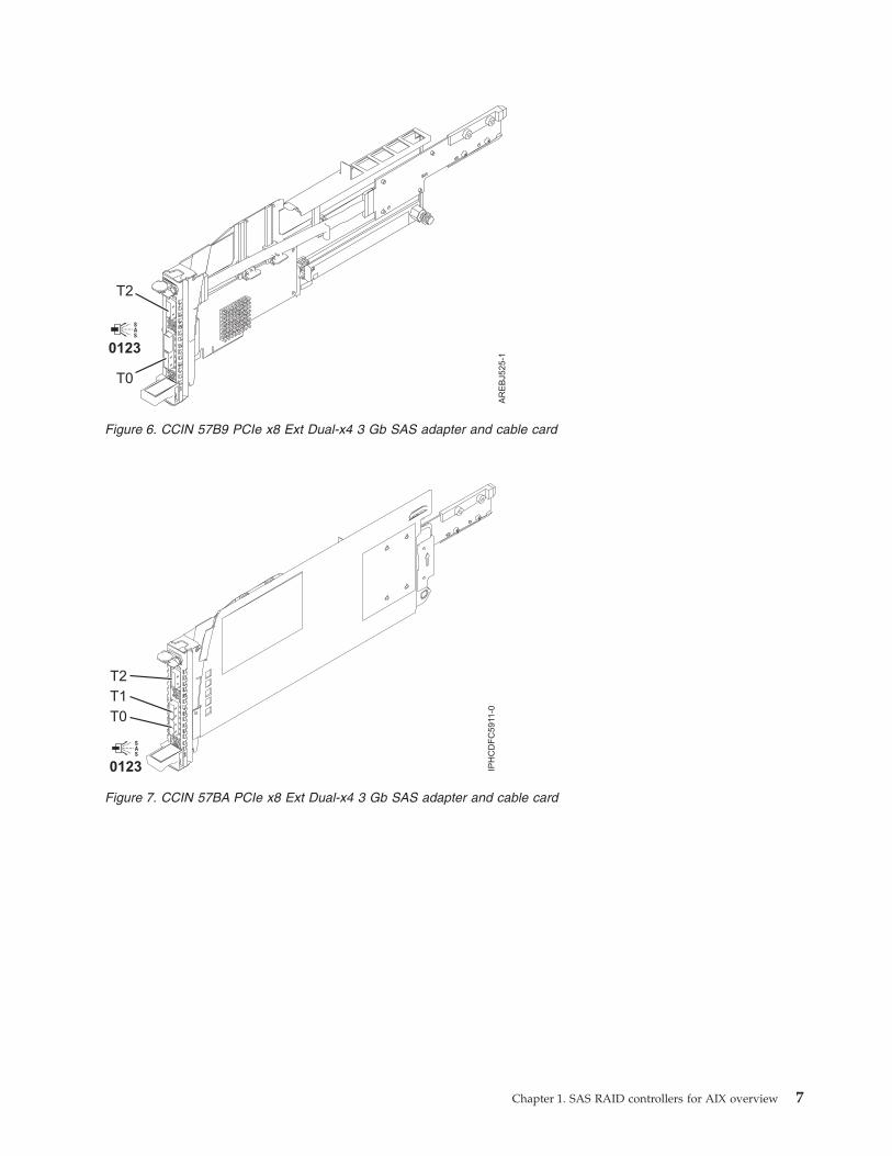
Figure 6. CCIN 57B9 PCIe x8 Ext Dual-x4 3 Gb SAS adapter and cable card
Figure 7. CCIN 57BA PCIe x8 Ext Dual-x4 3 Gb SAS adapter and cable card
Chapter 1. SAS RAID controllers for AIX overview 7

SAS architectureSerial-attached SCSI (SAS) architecture defines a serial device interconnect and transport protocol thatdefines the rules for information exchange between devices.
Figure 8. CCIN 57B3 PCIe x8 Ext Dual-x4 3 Gb SAS adapter
Figure 9. CCIN 574E PCIe x8 Ext Dual-x4 3 Gb SAS RAID adapter
8

SAS is an evolution of the parallel SCSI device interface into a serial point-to-point interface. SASphysical links (phys) are a set of four wires used as two differential signal pairs. One differential signaltransmits in one direction, while the other differential signal transmits in the opposite direction. Data canbe transmitted in both directions simultaneously. Phys are contained in SAS ports which contain one ormore phys. A port is a wide port if there are more than one phy in the port. If there is only one phy inthe port, it is a narrow port. A port is identified by a unique SAS worldwide name (also called SASaddress).
A SAS controller contains one or more SAS ports. A path is a logical point-to-point link between a SASinitiator port in the controller and a SAS target port in the I/O device (for example a disk). A connectionis a temporary association between a controller and an I/O device through a path. A connection enablescommunication to a device. The controller can communicate to the I/O device over this connection byusing either the SCSI command set or the ATA/ATAPI command set depending on the device type.
A SAS expander enables connections between a controller port and multiple I/O device ports by routingconnections between the expander ports. Only a single connection through an expander can exist at anygiven time. Using expanders creates more nodes in the path from the controller to the I/O device. If anI/O device supports multiple ports, more than one path to the device can exist when there are expanderdevices included in the path.
A SAS fabric refers to the summation of all paths between all SAS controller ports and all I/O deviceports in the SAS subsystem including cables, enclosures, and expanders.
The following example SAS subsystem shows some of the concepts described in this SAS overview. Acontroller is shown with eight SAS phys. Four of those phys are connected into two different wide ports.One connector contains four phys grouped into two ports. The connectors have no significance in SASother than causing a physical wire connection. The four-phy connector can contain between one and fourports depending on the type of cabling that is used. The uppermost port in the figure shows acontroller-wide port number 6 that consists of phy numbers 6 and 7. Port 6 connects to an expander,which attaches to one of the dual ports of the I/O devices. The dashed red line indicates a path betweenthe controller and an I/O device. Another path runs from the controller’s port number 4 to the other portof the I/O device. These two paths provide two different possible connections for increased reliability byusing redundant controller ports, expanders, and I/O device ports. The SCSI Enclosure Services (SES) is acomponent of each expander.
Figure 10. Example SAS Subsystem
Chapter 1. SAS RAID controllers for AIX overview 9

Disk arraysDisk arrays are groups of disks that work together with a specialized array controller to take advantageof potentially higher data transfer rates and, depending on the RAID level selected, data redundancy.
Disk arrays use RAID technology to offer data redundancy and improved data transfer rates over thoseprovided by single large disks. If a disk failure occurs, the disk can usually be replaced withoutinterrupting normal system operation.
Data redundancy
The disk array controller keeps track of how the data is distributed across the disks. RAID 5, 6, and 10disk arrays also provide data redundancy, so that no data is lost if a single disk in the array fails. If adisk failure occurs, the disk can usually be replaced without interrupting normal system operation.
Using arrays
Each disk array can be used by AIX in the same way as it would a single non-RAID disk. For example,after creating a disk array, you can create a file system on the disk array or use AIX commands to makethe disk array available to the system by adding the disk array to a volume group.
hdisk
Like other disk storage units in AIX, the disk arrays are assigned names using the hdisk form. The namesare deleted when you delete the disk array. An hdisk is a disk that is formatted to 512 bytes per sector.These disks must be formatted to 528 bytes per sector before they can be used in disk arrays.
pdisk
The individual physical disks that comprise disk arrays (or serve as candidates to be used in disk arrays)are represented by pdisk names. A pdisk is a disk that is formatted to 528 bytes per sector.
Array management
The IBM SAS RAID controller is managed by the IBM SAS Disk Array Manager. The disk array managerserves as the interface to the controller and I/O device configuration. It is also responsible for themonitoring and recovery features of the controller.
Boot device
If a disk array is to be used as the boot device, you might have to prepare the disks by booting from theIBM server hardware stand-alone diagnostics CD and creating the disk array before installing AIX. Youmight want to perform this procedure when the original boot drive is to be used as part of a disk array.
Array configuration
The following figure illustrates a possible disk array configuration.
10

The List SAS Disk Array Configuration option in the disk array manager can be used to display thepdisk and hdisk names, their associated location codes, and their current state of operation. Thefollowing sample output is displayed when the List SAS Disk Array Configuration option is invoked.
+--------------------------------------------------------------------------------+| || ------------------------------------------------------------------------ || Name Resource State Description Size || ------------------------------------------------------------------------ || sissas0 FFFFFFFF Primary PCI-X266 Planar 3 Gb SAS Adapter || || hdisk8 00FF0100 Optimal RAID 6 Array 69.6GB || pdisk0 00040100 Active Array Member 34.8GB || pdisk2 00040B00 Active Array Member 34.8GB || pdisk8 00000500 Active Array Member 34.8GB || pdisk9 00000A00 Active Array Member 34.8GB || || hdisk7 00FF0000 Optimal RAID 0 Array 34.8GB || pdisk4 00040000 Active Array Member 34.8GB || || hdisk13 00FF0300 Optimal RAID 0 Array 34.8GB || pdisk5 00040300 Active Array Member 34.8GB || || hdisk14 00FF0400 Failed RAID 0 Array 34.8GB || pdisk3 00040A00 Failed Array Member 34.8GB || || hdisk0 00040500 Available SAS Disk Drive 146.8GB || hdisk1 00040600 Available SAS Disk Drive 146.8GB || hdisk3 00000600 Available SAS Disk Drive 73.4GB || || |+--------------------------------------------------------------------------------+
Figure 11. Disk array configuration
Chapter 1. SAS RAID controllers for AIX overview 11

Related tasks
“Preparing disks for use in SAS disk arrays” on page 26Use this information to prepare disks for use in an array.“Viewing the disk array configuration” on page 29Use this procedure to view SAS disk array configurations on your server.
Supported RAID levelsThe RAID level of a disk array determines how data is stored on the disk array and the level ofprotection that is provided.
If a part of the RAID system fails, different RAID levels help to recover lost data in different ways. Withthe exception of RAID level 0, if a single drive fails within an array, the array controller can reconstructthe data for the Failed disk by using the data stored on other hard drives within the array. This datareconstruction has little or no impact to current system programs and users. The controller supportsRAID levels 0, 5, 6, and 10. Not all controllers support all RAID levels. Each RAID level supported by thecontroller has its own attributes and uses a different method of writing data. The following informationprovides details for each supported RAID level.Related concepts
“PCI-X SAS RAID card comparison” on page 1This table compares the main features of PCI-X SAS RAID cards.“PCIe SAS RAID card comparison” on page 5This table compares the main features of PCI Express (PCIe) SAS RAID cards.
RAID 0Learn how data is written to a RAID 0 array.
RAID 0 stripes data across the disks in the array, for optimal performance. For a RAID 0 array of threedisks, data would be written in the following pattern.
RAID 0 offers a high potential I/O rate, but it is a nonredundant configuration. As a result, there is nodata redundancy available for the purpose of reconstructing data in the event of a disk failure. There isno error recovery beyond what is normally provided on a single disk. Unlike other RAID levels, the array
Figure 12. RAID 0
12

controller never marks a RAID 0 array as Degraded as the result of a disk failure. If a physical disk failsin a RAID 0 disk array, the disk array is marked as Failed. All data in the array must be backed upregularly to protect against data loss.
RAID 5Learn how data is written to a RAID 5 array.
RAID 5 stripes data across all disks in the array. RAID level 5 also writes array parity data. The paritydata is spread across all the disks. For a RAID 5 array of three disks, array data and parity informationare written in the following pattern:
If a disk fails in a RAID 5 array, you can continue to use the array normally. A RAID 5 array operatingwith a single Failed disk is said to be operating in Degraded mode. Whenever data is read from aDegraded disk array, the array controller recalculates the data on the Failed disk by using data and parityblocks on the operational disks. If a second disk fails, the array will be placed in the Failed state and willnot be accessible.Related concepts
“Stripe-unit size” on page 16With RAID technology, data is striped across an array of physical disks. This data distribution schemecomplements the way that the operating system requests data.
RAID 6Learn how data is written to a RAID 6 array.
RAID 6 stripes data across all disks in the array. RAID level 6 also writes array ″P″ and ″Q″ parity data.The P and Q parity data, is spread across all the disks. For a RAID 6 array of four disks, array data andparity information are written in the following pattern:
Figure 13. RAID 5
Chapter 1. SAS RAID controllers for AIX overview 13

If one or two disks fail in a RAID 6 array, you can continue to use the array normally. A RAID 6 arrayoperating with a one or two Failed disks is said to be operating in Degraded mode. Whenever data isread from a Degraded disk array, the array controller recalculates the data on the failed disks by usingdata and parity blocks on the operational disks. A RAID 6 array with a single failed disk has similarprotection to that of a RAID 5 array with no disk failures. If a third disk fails, the array will be placed inthe Failed state and will not be accessible.
RAID 10Learn how data is written to a RAID 10 array.
RAID 10 uses mirrored pairs to redundantly store data. The array must contain an even number of disks.Two is the minimum number of disks needed to create a RAID 10 array. The data is striped across themirrored pairs. For example, a RAID 10 array of four disks would have data written to it in the followingpattern:
Figure 14. RAID 6
Figure 15. RAID 10
14

RAID 10 tolerates multiple disk failures. If one disk in each mirrored pair fails, the array will still befunctional, operating in Degraded mode. You can continue to use the array normally because for eachFailed disk, the data is stored redundantly on its mirrored pair. However, if both members of a mirroredpair fail, the array will be placed in the Failed state and will not be accessible.
When a RAID 10 disk array is created, the controller will automatically attempt to select the disks foreach mirrored pair from a different controller connector (a different cable to a different device enclosure).For example, if four disks selected for the disk array are located on one of the controller’s connectors andanother four disks selected are located on another of the controller’s connectors, the controller willautomatically attempt to create each mirrored pair from one disk on each controller connector. In theevent of a controller port, cable, or enclosure failure, each mirrored pair will continue to operate in aDegraded mode. Such redundancy requires careful planning when you are determining where to placedevices.
Disk array capacitiesThese guidelines will help you calculate the capacity of a disk array.
The capacity of a disk array depends on the capacity of the disks used and the RAID level of the array.To calculate the capacity of a disk array, do the following:
RAID 0Multiply the number of disks by the disk capacity.
RAID 5Multiply one fewer than the number of disks by the disk capacity.
RAID 6Multiply two fewer than the number of disks by the disk capacity.
RAID 10Multiply the number of disks by the disk capacity and divide by 2.
Note: If disks of different capacities are used in the same array, all disks are treated as if they have thecapacity of the smallest disk.
RAID level summaryCompare RAID levels according to their capabilities.
The following information provides data redundancy, usable disk capacity, read performance, and writeperformance for each RAID level.
Table 3. RAID level summary
RAID level Data redundancyUsable diskcapacity
Readperformance
Writeperformance
Min/Max devicesper array
RAID 0 None 100% Very good Excellent 1/18
RAID 5 Very good 67% to 94% Very good Good 3/18
RAID 6 Excellent 50% to 89% Very good Fair to good 4/18
RAID 10 Excellent 50% Excellent Very good 2/18 (evennumbers only)
RAID 0Does not support data redundancy, but provides a potentially higher I/O rate.
RAID 5Creates array parity information so that the data can be reconstructed if a disk in the array fails.Provides better capacity than RAID level 10 but possibly lower performance.
Chapter 1. SAS RAID controllers for AIX overview 15

RAID 6Creates array ″P″ and ″Q″ parity information so that the data can be reconstructed if one or twodisks in the array fail. Provides better data redundancy than RAID 5 but with slightly lowercapacity and possibly lower performance. Provides better capacity than RAID level 10 butpossibly lower performance.
RAID 10Stores data redundantly on mirrored pairs to provide maximum protection against disk failures.Provides generally better performance than RAID 5 or 6, but has lower capacity.
Note: A two-drive RAID level 10 array is equivalent to RAID level 1.
Stripe-unit sizeWith RAID technology, data is striped across an array of physical disks. This data distribution schemecomplements the way that the operating system requests data.
The granularity at which data is stored on one disk of the array before subsequent data is stored on thenext disk of the array is called the stripe-unit size. The collection of stripe units, from the first disk of thearray to the last disk of the array, is called a stripe.
You can set the stripe-unit size of an IBM SAS Disk Array to 16 KB, 64 KB, 256 KB, or 512 KB. You mightbe able to maximize the performance of your disk array by setting the stripe-unit size to a value that isslightly larger than the size of the average system I/O request. For large system I/O requests, use astripe-unit size of 256 KB or 512KB. The recommended stripe size will be identified on the screen whenyou create the disk array.
Valid states for hdisks and pdisksDisk arrays and physical disks have several operational states.
States for disk arrays (hdisks)There are six valid states for disk arrays.
The valid states for IBM SAS Disk Arrays are Optimal, Degraded, Rebuilding, Failed, Missing, andUnknown.
OptimalThe array is functional and fully protected (RAID 5, 6, and 10) with all array member pdisks inthe Active state.
DegradedThe array’s protection against disk failures is degraded or its performance is degraded. When oneor more array member pdisks are in the Failed state, the array is still functional but might nolonger be fully protected against disk failures. When all array member pdisks are in the Activestate, the array is not performing optimally because of a problem with the controller’s nonvolatilewrite cache.
RebuildingRedundancy data for the array is being reconstructed. After the rebuild process has completed,the array will return to the Optimal state. Until then, the array is not fully protected against diskfailures.
Failed The array is no longer accessible because of disk failures or configuration problems.
MissingA previously configured disk array no longer exists.
UnknownThe state of the disk array could not be determined.
16

States for physical disks (pdisks)There are five valid states for physical disks.
The valid states for pdisks are Active, RWProtected, Failed, Missing, and Unknown.
ActiveThe disk is functioning correctly.
RWProtectedThe disk is unavailable because of a hardware or a configuration problem.
Failed The controller cannot communicate with the disk, or the pdisk is the cause of the disk arraybeing in a Degraded state.
MissingThe disk was previously connected to the controller but is no longer detected.
UnknownThe state of the disk could not be determined.
pdisk descriptionsThe pdisk description indicates whether the disk is configured as an Array Member, Hot Spare, or anArray Candidate.
For an array, the description column of the List SAS Disk Array Configuration screen indicates theRAID level of the array. The description column for a pdisk indicates whether the disk is configured asan Array Member, Hot Spare, or an Array Candidate.
Array MemberA 528 bytes per sector pdisk that is configured as a member of an array.
Hot SpareA 528 bytes per sector pdisk that can be used by the controller to automatically replace a Faileddisk in a Degraded RAID 5, 6, or 10 disk array. A Hot Spare disk is useful only if its capacity isgreater than or equal to the capacity of the smallest disk in an array that becomes Degraded. Formore information about hot spare disks, see “Using hot spare disks” on page 32.
Array CandidateA 528 bytes per sector pdisk that is a candidate for becoming an Array Member or a Hot Spare.
Auxiliary write cacheA duplicate, nonvolatile copy of write cache data can be preserved.
Auxiliary write cache adapterThe Auxiliary Write Cache (AWC) adapter provides a duplicate, nonvolatile copy of write cache data ofthe RAID controller to which it is connected.
Protection of data is enhanced by having two battery-backed (nonvolatile) copies of write cache, eachstored on separate adapters. If a failure occurs to the write cache portion of the RAID controller, or theRAID controller itself fails in such a way that the write cache data is not recoverable, the AWC adapterprovides a backup copy of the write cache data to prevent data loss during the recovery of the failedRAID controller. The cache data is recovered to the new replacement RAID controller and then writtenout to disk before resuming normal operations.
The AWC adapter is not a failover device that can keep the system operational by continuing diskoperations when the attached RAID controller fails. The system cannot use the auxiliary copy of thecache for runtime operations even if only the cache on the RAID controller fails. The AWC adapter doesnot support any other device attachment and performs no other tasks than communicating with theattached RAID controller to receive backup write cache data. The purpose of the AWC adapter is to
Chapter 1. SAS RAID controllers for AIX overview 17

minimize the length of an unplanned outage, due to a failure of a RAID controller, by preventing loss ofcritical data that might have otherwise required a system reload.
It is important to understand the difference between multi-initiator connections and AWC connections.Connecting controllers in a multi-initiator environment refers to multiple RAID controllers connected to acommon set of disk enclosures and disks. The AWC controller is not connected to the disks, and it doesnot perform device media accesses.
Important: If a failure of either the RAID controller or the Auxiliary Cache occurs, the MaintenanceAnalysis Procedures (MAPs) for the service request numbers (SRNs) in the AIX error log must befollowed precisely.
The RAID controller and the AWC adapter each require a PCI bus connection and are required to be inthe same partition. The two adapters are connected by an internal SAS connection. For the Planar RAIDEnablement and Planar Auxiliary Cache features, the dedicated SAS connection is integrated into thesystem planar.
If the AWC adapter itself fails or the SAS link between the two adapters fails, the RAID controller willstop caching operations, destage existing write cache data to disk, and run in a performance-degradedmode. After the AWC adapter is replaced or the link is reestablished, the RAID controller automaticallyrecognizes the AWC, synchronizes the cache area, resumes normal caching function, and resumes writingthe duplicate cache data to the AWC.
The AWC adapter is typically used in conjunction with RAID protection. RAID functions are not affectedby the attachment of an AWC. Because the AWC does not control other devices over the bus andcommunicates directly with its attached RAID controller over a dedicated SAS bus, it has little, if any,performance impact on the system.
Figure 16. Example RAID and AWC controller configuration
18

Related concepts
Chapter 4, “Multi-initiator and high availability,” on page 37You can increase availability using multi-initiator and high availability to connect multiple controllers to acommon set of disk expansion drawers.Chapter 6, “Problem determination and recovery,” on page 83AIX diagnostics and utilities are used to assist in problem determination and recovery tasks.
Installing the auxiliary write cacheFollow these step-by-step instructions to install the auxiliary write cache.
Note: Disk arrays can be previously configured or new arrays can be created after the auxiliary cacheenvironment configuration is set up.1. Ensure that both the storage I/O adapter and AWC adapter are installed in the same partition and in
the same enclosure.2. Update to the latest adapter microcode from the code download web site, and to the required levels
of both the AIX version and the AIX driver package for your specific adapters. See AIX softwarerequirements for the required code levels, and also refer to the installation information for the adapter.
3. Power on the system or partition and verify the function of adapters and disk arrays. See “Viewingthe disk array configuration” on page 29. The output displayed will be similar to the following screenexamples.
+--------------------------------------------------------------------------------+| COMMAND STATUS || || Command: OK stdout: yes stderr: no || || Before command completion, additional instructions can appear below. || || ------------------------------------------------------------------------ || Name Resource State Description Size || ------------------------------------------------------------------------ || sissas2 FFFFFFFF Available PCIe x1 Auxiliary Cache Adapter || sissas1 FFFFFFFF AWC linked Redundant cache protected by sissas2 || || || || || || || || || F1=Help F2=Refresh F3=Cancel F6=Command || F8=Image F9=Shell F10=Exit /=Find || n=Find Next |+--------------------------------------------------------------------------------+
Chapter 1. SAS RAID controllers for AIX overview 19

+--------------------------------------------------------------------------------+| COMMAND STATUS || || Command: OK stdout: yes stderr: no || || Before command completion, additional instructions might appear below. || || ------------------------------------------------------------------------ || Name Resource State Description Size || ------------------------------------------------------------------------ || sissas1 FFFFFFFF Primary PCI-X266 Planar 3 Gb SAS RAID Adapter || sissas2 FFFFFFFF AWC linked Redundant cache protection for sissas1 || || pdisk2 00044000 Active Array Candidate 69.7GB Zeroed || pdisk4 00044100 Active Array Candidate 69.7GB Zeroed || pdisk3 00044200 Active Array Candidate 69.7GB Zeroed || pdisk5 00044300 Active Array Candidate 69.7GB Zeroed || pdisk7 00044400 Active Array Candidate 139.6GB || pdisk0 00044500 Active Array Candidate 139.6GB || pdisk1 00044600 Active Array Candidate 139.6GB || || || || F1=Help F2=Refresh F3=Cancel F6=Command || F8=Image F9=Shell F10=Exit /=Find || n=Find Next |+--------------------------------------------------------------------------------+
4. Verify that both adapters indicate they are Available and AWC Linked to the other adapter, and thatall arrays indicate Optimal.
Viewing link status informationYou can view more detailed link status information in the Change/Show SAS Controller informationscreen.1. Navigate to the IBM SAS Disk Array Manager by using the steps found in “Using the Disk Array
Manager” on page 25.2. Select Diagnostics and Recovery Options.3. Select Change/Show SAS RAID controller.4. Select the IBM SAS RAID or AWC Controller. The screen displayed will look similar to the following
screen.
20

+---------------------------------------------------------------------------------+| Change/Show SAS Controller || || Type or select values in entry fields. || Press Enter AFTER making all desired changes. || || [Entry Fields] || SAS adapter sissas2 || Description PCIe x1 Auxilia> || Status Available || Location 06-00 || Operating mode Aux Write Cache Adapte> || Preferred Dual Initiator Operating mode No Preference || Dual Initiator Configuration Default || Serial Number YL3126327310 || World Wide ID 5005076c0702bf00 || Remote HA Link Operational No || Remote HA Serial Number || Remote HA World Wide ID || Remote AWC Link Operational Yes || Remote AWC Serial Number 07127001 || Remote AWC World Wide ID 5005076c0702f600 || || F1=Help F2=Refresh F3=Cancel F4=List || F5=Reset F6=Command F7=Edit F8=Image || F9=Shell F10=Exit Enter=Do |+---------------------------------------------------------------------------------+
Chapter 1. SAS RAID controllers for AIX overview 21

22

Chapter 2. Controller software
For the controller to be identified and configured by AIX, the requisite device support software must beinstalled. The requisite software for the controller is often preinstalled during AIX installation.
It might be necessary to perform operations related to the installation, verification, and maintenance ofthe AIX device software for the controller.
Software for the controller is packaged in installp format and distributed as part of the base AIXinstallation media, AIX update media, and through the Web-based Fix Delivery Center for AIX. Thisinformation is an overview of the AIX software support required for the controller. For completeinformation related to the installation and maintenance of AIX, refer to the IBM System p® and AIXInformation Center Web site.
The controller runs onboard microcode. The AIX command lsmcode can be used to determine the level ofonboard microcode being used by the controller. Although a version of controller microcode might bedistributed along with AIX, this does not necessarily represent the most recent version of microcodeavailable for the controller.Related tasks
“Updating the SAS RAID controller microcode” on page 59Determine if you need to update your SAS RAID controller microcode, then download and install theupdates.
Controller software verificationSupport for the controller is contained in the AIX package named devices.common.IBM.sissas.
Each controller requires an AIX package described by the following table. These device support packagescontain multiple filesets, each related to a different aspect of device support.
Attention: Ensure the adapters are updated with the latest microcode from the Microcode downloads aspart of the initial installation.
Table 4. AIX software requirements
CCIN (customcardidentificationnumber) AIX Package Minimum Required AIX Version
572A devices.pci.1410bd02 Refer to the PCI Adapter Information by Feature Type information atManaging PCI adapters for the Minimum AIX level requirements.
572B devices.pci.1410bd02 Refer to the PCI Adapter Information by Feature Type information atManaging PCI adapters for the Minimum AIX level requirements.
572C devices.pci.1410bd02 One of the following:
v AIX 5L™ Version 5.2 with Technology Level 10 (5200-10)
v AIX 5L Version 5.3 with Technology Level 6 (5300-06) or later
572F/575C devices.pci.1410bd02 Refer to the PCI Adapter Information by Feature Type information atManaging PCI adapters for the Minimum AIX level requirements.
574E devices.pciex.14103903 Refer to the PCI Adapter Information by Feature Type information atManaging PCI adapters for the Minimum AIX level requirements.
© Copyright IBM Corp. 2007, 2009 23

Table 4. AIX software requirements (continued)
CCIN (customcardidentificationnumber) AIX Package Minimum Required AIX Version
57B3 devices.pciex.14103903 Refer to the PCI Adapter Information by Feature Type information atManaging PCI adapters for the Minimum AIX level requirements.
57B7 devices.pciex.14103903 One of the following:
v AIX Version 6.1 with Technology Level 0 (6100-00)
v AIX 5L Version 5.3 with Technology Level 7 (5300-07), or later
v AIX 5L Version 5.3 with Technology Level 6 and Service Pack 7(5300-06-07), or later
57B8 devices.pci.1410bd02 One of the following:
v AIX Version 6.1 with Technology Level 0 (6100-00)
v AIX 5L Version 5.3 with Technology Level 7 (5300-07), or later
v AIX 5L Version 5.3 with Technology Level 6 and Service Pack 7(5300-06-07), or later
57B9 devices.pciex.14103903 One of the following:
v AIX Version 6.1 with Technology Level 1 (6100-01)
v AIX 5L Version 5.3 with Technology Level 8 (5300-08), or later
57BA devices.pciex.14103903 Refer to the PCI Adapter Information by Feature Type information atManaging PCI adapters for the Minimum AIX level requirements.
To verify that the device support package for the controller is installed, type as an example:
lslpp -l devices.common.IBM.sissas
Output from this command indicates if device support software for the controller is installed, and if so,what the corresponding levels of each fileset are.
If the output indicates that no filesets of this name are installed, you must install the appropriate packageso that the controller can be available for use. This software package is available as part of the base AIXinstallation media, AIX update media, and through the Web-based Fix Delivery Center for AIX.
Over time, it might become necessary to install software updates so that you have the very latestavailable level of device software support for the controller. Updates to the device support software arepackaged, distributed, and installed through the same mechanisms used for other portions of the AIXbase operating system. The standard AIX technical support procedures can be used to determine thelatest available level of device software support for the controller.
24
Chapter 3. Common controller and disk array managementtasks
You can perform various tasks to manage SAS RAID disk arrays.
Use the information in this section to manage your RAID disk arrays.
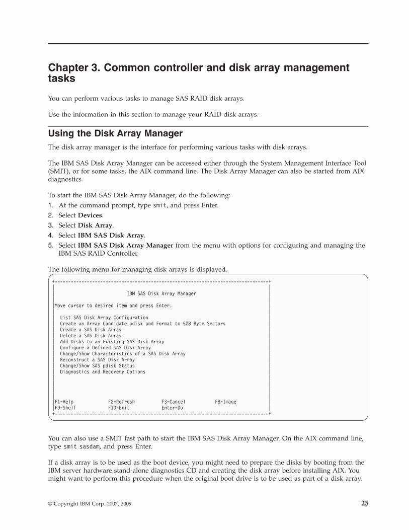
Using the Disk Array ManagerThe disk array manager is the interface for performing various tasks with disk arrays.
The IBM SAS Disk Array Manager can be accessed either through the System Management Interface Tool(SMIT), or for some tasks, the AIX command line. The Disk Array Manager can also be started from AIXdiagnostics.
To start the IBM SAS Disk Array Manager, do the following:1. At the command prompt, type smit, and press Enter.2. Select Devices.3. Select Disk Array.4. Select IBM SAS Disk Array.5. Select IBM SAS Disk Array Manager from the menu with options for configuring and managing the
IBM SAS RAID Controller.
The following menu for managing disk arrays is displayed.
+--------------------------------------------------------------------------------+| || IBM SAS Disk Array Manager || ||Move cursor to desired item and press Enter. || || List SAS Disk Array Configuration || Create an Array Candidate pdisk and Format to 528 Byte Sectors || Create a SAS Disk Array || Delete a SAS Disk Array || Add Disks to an Existing SAS Disk Array || Configure a Defined SAS Disk Array || Change/Show Characteristics of a SAS Disk Array || Reconstruct a SAS Disk Array || Change/Show SAS pdisk Status || Diagnostics and Recovery Options || || || || ||F1=Help F2=Refresh F3=Cancel F8=Image ||F9=Shell F10=Exit Enter=Do |+--------------------------------------------------------------------------------+
You can also use a SMIT fast path to start the IBM SAS Disk Array Manager. On the AIX command line,type smit sasdam, and press Enter.
If a disk array is to be used as the boot device, you might need to prepare the disks by booting from theIBM server hardware stand-alone diagnostics CD and creating the disk array before installing AIX. Youmight want to perform this procedure when the original boot drive is to be used as part of a disk array.
© Copyright IBM Corp. 2007, 2009 25

To start the IBM SAS Disk Array Manager from the AIX diagnostics, do the following:1. Start the AIX diagnostics, and on the Function Selection screen, select Task Selection.2. Select RAID Array Manager and press Enter.3. Select IBM SAS Disk Array Manager and press Enter.Related concepts
“AIX command-line interface” on page 35Many tasks used to manage the SAS RAID controller can be performed by using the AIX command lineinstead of using the SAS Disk Array Manager.
Preparing disks for use in SAS disk arraysUse this information to prepare disks for use in an array.
Before a disk can be used in a disk array, it must be a 528 bytes per sector Array Candidate pdisk. Tocreate an Array Candidate pdisk and format it to 528 byte sectors, do the following:1. Start the IBM SAS Disk Array Manager by following the steps in “Using the Disk Array Manager” on
page 25.2. Select Create an Array Candidate pdisk and Format to 528 Byte Sectors.3. Select the appropriate controller.4. Select the disks that you want to prepare for use in the SAS disk arrays.
Attention: Continuing with this option will format the disks. All data on the disks will be lost. Somedisks require that their microcode be updated to the latest level before being formatted to 528 bytesectors.A message will display asking if you want to continue.
5. To proceed with the format, select OK or press Enter to continue. To return to the previous menuwithout formatting the disks, select Cancel.
After the formatting is complete, the disks will be Array Candidate pdisks and will be ready for use indisk arrays. This operation will also zero all the data on the disks. The controller keeps track of the disksthat have their data zeroed. These Zeroed Array Candidate pdisks can be used to create a disk array thatwill be immediately protected against disk failures, and they are the only disks that can be added to anexisting disk array. An Array Candidate pdisk will lose its Zeroed state after it has been used in an arrayor is unconfigured. It will also lose its Zeroed state after the system has been rebooted or the controllerhas been unconfigured. To return an Array Candidate pdisk to the Zeroed state, follow the stepspreviously described in this section for preparing disks for use in disk arrays. For more information, see“Disk arrays” on page 10.
Creating a disk arrayA disk array is created using a set of Active Array Candidate pdisks.
For disk arrays with data redundancy (RAID 5, 6, and 10), if all of the pdisks are in the Zeroed state, thearray will become immediately protected against failures. However, if one or more of the pdisks are notZeroed, the newly created array will initially be in the Rebuilding state. It will be unprotected againstdisk failures until parity data on all of the disks has been recalculated. For disk arrays with no dataredundancy (RAID 0), it is of no importance whether the pdisks are in the Zeroed state.
To create a IBM SAS Disk Array, do the following:1. Start the IBM SAS Disk Array Manager by following the steps in “Using the Disk Array Manager” on
page 25.2. Select Create a IBM SAS Disk Array.3. Select the appropriate IBM SAS RAID Controller on which you want to create an array.
26

4. Select the RAID level for the array. For more information about selecting an appropriate RAID level,see “Supported RAID levels” on page 12.
5. Select the stripe size in kilobytes for the array. For more information about the stripe-size parameter,see “Stripe-unit size” on page 16.A selection screen similar to the following representation displays. It will display a list of ArrayCandidate pdisks and notes regarding array requirements. The minimum and maximum number ofsupported disks will be specified, along with any other specific requirements for the array. Select thedisks that you want to use in the array according to the requirements on this screen.
+--------------------------------------------------------------------------+| Select Disks to Use in the Array || || Move cursor to desired item and press F7. Use arrow keys to scroll. || ONE OR MORE items can be selected. || Press Enter AFTER making all selections. || || # RAID 5 supports a minimum of 3 and a maximum of 18 drives. || || || pdisk1 00040200 Active Array Candidate 34.8GB || pdisk3 00040900 Active Array Candidate 34.8GB || pdisk4 00040000 Active Array Candidate 34.8GB || pdisk5 00040300 Active Array Candidate 34.8GB || || F1=Help F2=Refresh F3=Cancel || F7=Select F8=Image F10=Exit || Enter=Do /=Find n=Find Next |+--------------------------------------------------------------------------+
A SMIT Dialog Screen summarizes your selections.6. Press Enter to create the array.
You can now add the disk array to a volume group. Logical volumes and file systems can also be created.Use standard AIX procedures to perform these tasks, and treat the array in the same way that you wouldtreat any hdisk.
Migrating an existing disk array to a new RAID levelThe SAS RAID controller supports migrating an existing RAID 0 or 10 disk array to RAID 10 or 0,respectively. This allows you to dynamically change the level of protection of a disk array whilepreserving its existing data.
When migrating RAID 0 to RAID 10, additional disks must be included into the RAID 10 disk array inorder to provide the additional level of protection. The number of additional disks will be equal to thenumber of disks in the original RAID level 0 disk array. The capacity of the disk array will remainunchanged and the disk array remains accessible during the migration. The disk array is not protected byRAID 10 until the migration completes.
When migrating RAID 10 to RAID 0, no additional disks are included into the RAID 0 disk array. Thenumber of disks in the resulting RAID 0 disk array will be reduced to half the number of disks in theoriginal RAID 10 disk array. The capacity of the disk array will remain unchanged and the disk arrayremains accessible during the migration.
To migrate an existing array to a new level, do the following:1. Start the SAS Disk Array Manager by following the steps in “Using the Disk Array Manager” on page
25.2. Select Migrate an Existing SAS Disk Array to a New RAID Level.3. Select the SAS disk array which you want to migrate to a new level.4. Select the desired RAID level from the options shown.
Chapter 3. Common controller and disk array management tasks 27

5. Select the desired stripe size from the options shown.6. Select additional disks to include if necessary to provide the desired level or protection. A screen will
display similar to the following:
+--------------------------------------------------------------------------------+| IBM SAS Disk Array Manager || ||Move cursor to desired item and press Enter. || || List SAS Disk Array Configuration || Create an Array Candidate pdisk and Format to 528 Byte Sectors || Create a SAS Disk Array || Delete a SAS Disk Array || Add Disks to an Existing SAS Disk Array || Migrate an Existing SAS Disk Array to a New RAID Level || +--------------------------------------------------------------------------+ || | Include Disks during an SAS Disk Array Migration | || | | || | Move cursor to desired item and press F7. Use arrow keys to scroll. | || | ONE OR MORE items can be selected. | || | Press Enter AFTER making all selections. | || | | || | # hdisk6 requires 1 additional drives (maximum of 1) for RAID 10. | || | | || | pdisk24 00044000 Active Array Candidate 139.6GB | || | | || | F1=Help F2=Refresh F3=Cancel | || | F7=Select F8=Image F10=Exit | ||F1| Enter=Do /=Find n=Find Next | ||F9+--------------------------------------------------------------------------+ |+--------------------------------------------------------------------------------+
7. Press Enter to perform the RAID level migration.The migration progress percentage will be displayed next to the array being migrated.A screen will display similar to the following.
Note: If the RAID disk array is in use, the RAID level description might not be updated until afterthe next IPL.
+--------------------------------------------------------------------------------+| COMMAND STATUS || ||Command: OK stdout: yes stderr: no || ||Before command completion, additional instructions might appear below. || ||------------------------------------------------------------------------ ||Name Resource State Description Size ||------------------------------------------------------------------------ ||sissas1 FFFFFFFF Primary PCI Express x8 Ext Dual-x4 3 Gb SAS RAID Adapter ||tmscsi0 00FE0000 HA Linked Remote adapter SN 081620E4 || ||hdisk1 00FF0000 Optimal RAID 6 Array 139.5GB || pdisk1 00040400 Active Array Member 69.7GB || pdisk2 00040800 Active Array Member 69.7GB || pdisk3 00040000 Active Array Member 69.7GB || pdisk4 00040100 Active Array Member 69.7GB || ||hdisk6 00FF0500 Rebuilding RAID 10 Array 139.6GB Migrate 8% || pdisk12 00040B00 Active Array Member 139.6GB || pdisk24 00044000 Active Array Member 139.6GB || || || ||F1=Help F2=Refresh F3=Cancel F6=Command ||F8=Image F9=Shell F10=Exit /=Find ||n=Find Next |+--------------------------------------------------------------------------------+
28

8. After the RAID level migration is completed, run cfgmgr to update the description of the disk array.
Viewing the disk array configurationUse this procedure to view SAS disk array configurations on your server.
To view the configuration of arrays and disks associated with a particular controller, do the following:1. Start the Disk Array Manager by following the steps in “Using the Disk Array Manager” on page 25.2. Select List IBM SAS Disk Array Configuration.3. Choose one or more controllers.
The output displayed will be similar to the following:
+--------------------------------------------------------------------------------+| || COMMAND STATUS || ||Command: OK stdout: yes stderr: no || ||Before command completion, additional instructions might appear below. || ||------------------------------------------------------------------------ ||Name Resource State Description Size ||------------------------------------------------------------------------ ||sissas0 FFFFFFFF Primary PCI-X266 Planar 3 Gb SAS RAID Adapter || ||hdisk7 00FF0000 Optimal RAID 5 Array 69.7GB || pdisk1 00040200 Active Array Member 34.8GB || pdisk3 00040900 Active Array Member 34.8GB || pdisk4 00040000 Active Array Member 34.8GB || ||hdisk8 00FF0100 Rebuilding RAID 6 Array 69.7GB Rebuild 13% || pdisk2 00040800 Active Array Member 34.8GB || pdisk7 00040B00 Active Array Member 34.8GB || pdisk9 00000A00 Active Array Member 34.8GB || pdisk11 00000900 Active Array Member 34.8GB || ||hdisk12 00FF0200 Optimal RAID 0 Array 34.8GB || pdisk5 00040300 Active Array Member 34.8GB || ||hdisk4 00FF0400 Rebuilding RAID 10 Array 69.7GB Create 8% || pdisk0 00040100 Active Array Member 69.7GB || pdisk6 00040400 Active Array Member 69.7GB || ||*unknwn* 00000500 Active Array Candidate N/A ||pdisk19 00060A00 Failed Array Candidate 34.8GB ||pdisk10 00000B00 Active Array Candidate 34.8GB Zeroed ||pdisk17 00000800 RWProtected Array Candidate 69.7GB Format 8% ||pdisk18 00000400 Active Array Candidate 69.7GB Zeroed ||pdisk16 00000600 RWProtected Array Candidate 69.7GB Format 7% || ||hdisk0 00040500 Available SAS Disk Drive 146.8GB ||hdisk1 00040700 Available SAS Disk Drive 146.8GB ||hdisk2 00040600 Available SAS Disk Drive 146.8GB || ||F1=Help F2=Refresh F3=Cancel F6=Command ||F8=Image F9=Shell F10=Exit /=Find ||n=Find Next |+--------------------------------------------------------------------------------+
The controller’s name, location, status, and description are displayed first. Each IBM SAS disk array hdiskis displayed with its Array Member pdisks directly underneath it.v The first column of output is the name of the disk array (hdisk) or physical disk (pdisk). Note the use
of *unknwn* to identify a device known by the controller but not configured in AIX.
Chapter 3. Common controller and disk array management tasks 29

v The second column of output is the device’s resource location (or simply “Resource”). This value mightalso be referred to as the device’s SCSI ID in other parts of AIX software documentation. For moreinformation on the format of the resource value, see “SAS resource locations” on page 83.
v The third column of the preceding screen is the state of the disk array or pdisk. For information aboutthe possible disk array and pdisk states, see “Disk arrays” on page 10. For 512 byte/sector standalonedisks (hdisks), this column is the AIX device state (for example, Available or Defined).
v The fourth column is a description of the device. For a disk array, the description is the RAID level ofthe array. For a pdisk, the description can be Array Candidate, Hot Spare, or Array Member.
v The fifth column is the capacity of the array or disk. For information about how the capacity of anarray is calculated for each RAID level, see “Disk array capacities” on page 15.
v The sixth column is the status of a long-running command issued to a disk array or pdisk. Thiscolumn is also used to indicate that an Array Candidate pdisk has had its data zeroed. If there is along-running command in progress, the percentage complete will be displayed after the command. Thefollowing values might be displayed (where nn% is the command percentage complete):
Create nn%Disk array is in process of being created.
Delete nn%Disk array is in process of being deleted.
Rebuild nn%Disk array is in process of being reconstructed.
Resync nn%Disk array is in process of having it parity data resynchronized.
Adding nn%Disk array is in process of having one or more disks added to it.
Format nn%pdisk is in process of being formatted.
Zeroedpdisk has been zeroed.
Array Candidate pdisks and Hot Spare pdisks are displayed at the bottom of this screen. The pdisknames are displayed, along with location, state, description, capacity, and long-running command status.Any 512 bytes per sector stand-alone disks (hdisks) are displayed, along with location, state, description,and capacity.
Deleting a disk arrayTo preserve the data on the disk array, you must first back up all files in the logical volumes and filesystems on the disk array before removing the disk array from its volume group.
Attention: After a disk array is deleted, it cannot be accessed. All data will be lost. A disk array that iscurrently in use or opened cannot be deleted. Also, if a disk array command (such as a disk creationcommand) is in progress, that disk array cannot be deleted.
To delete the array, do the following:1. Start the IBM SAS Disk Array Manager by following the steps in “Using the Disk Array Manager” on
page 25.2. Select Delete a IBM SAS Disk Array.3. Select the IBM SAS RAID Controller.4. Select the disk array to delete.
30

When the disk array has been deleted, any Active Array Member pdisks will become Active ArrayCandidate pdisks.
Adding disks to an existing disk arrayThe controller supports adding disks to existing RAID level 5 or 6 disk arrays, which allows you todynamically increase the capacity of a disk array while preserving its existing data.
After you add disks to an existing disk array, they are protected and become part of the disk array butwill not contain parity and the data will not be restriped. Use of this feature, however, will result in aperformance penalty. The first part of the performance penalty exists because not all the drives in thearray contain parity and therefore the drives with parity are accessed more often for parity updates. Thesecond part of the performance penalty comes from the data not being restriped and therefore reducingthe ability to use the hardware assisted stripe write features.
An Array Candidate pdisk is not necessarily a candidate that can be added to an existing array. Inaddition to being an Array Candidate, the pdisk must also be recognized by the adapter as having itsdata zeroed. This situation ensures that when the disks are added to the array, the parity data will becorrect and the array will remain protected against disk failures.
To add disks to an existing array, do the following:1. Ensure that the disks to be added are Zeroed Array Candidate pdisks. For assistance in viewing and
changing the state of the disk, see “Preparing disks for use in SAS disk arrays” on page 26 and“Viewing the disk array configuration” on page 29.
2. Start the IBM SAS Disk Array Manager by following the steps in “Using the Disk Array Manager” onpage 25.
3. Select Add Disks to an Existing SAS Disk Array.4. Select the IBM SAS Disk Array to which you want to add disks.
A screen will display similar to the following example. If a particular disk is not included in the list, itmight not be a candidate that can be added to the array because of the following reasons:v The disk’s capacity is less than that of the smallest disk already in the array.v The disk has not been formatted as a 528 bytes per sector Array Candidate pdisk.v The disk does not have its data zeroed.
For the second and third cases, the disk can be added to an array if it is first formatted using theCreate an Array Candidate pdisk and Format to 528 Byte Sectors option in the IBM SAS Disk ArrayManager.
+--------------------------------------------------------------------------------+| Add Disks to an Existing SAS Disk Array || Move cursor to desired item and press F7. Use arrow keys to scroll. || ONE OR MORE items can be selected. || Press Enter AFTER making all selections. || || # Choose up to 14 of the following disks to add to hdisk2 || || pdisk16 00000600 Active Array Candidate 69.7GB Zeroed || pdisk17 00000800 Active Array Candidate 69.7GB Zeroed || pdisk18 00040800 Active Array Candidate 69.7GB Zeroed || || # Note: If a disk is not listed here it is either not a candidate || # to be added to this array or it does not have its data zeroed || # Use the Create an Array Candidate pdisk and Format to 528 Byte || # Sectors option to format and zero the disk. || || F1=Help F2=Refresh F3=Cancel || F7=Select F8=Image F10=Exit || Enter=Do /=Find n=Find Next |+--------------------------------------------------------------------------------+
Chapter 3. Common controller and disk array management tasks 31

5. Press Enter to add the disks to the array.
To enable higher level components in the system to use the increased capacity of the disk array,additional steps might be needed.
Using hot spare disksHot spare disks are used to automatically replace a disk that has failed in a redundant RAIDenvironment.
Hot spare disks are useful only if their capacity is greater than or equal to that of the smallest capacitydisk in an array that becomes degraded.
Creating hot spare disksFollow this procedure to create hot spare disks.1. Start the IBM SAS Disk Array Manager by following the steps in “Using the Disk Array Manager” on
page 25.2. Select Change/Show SAS pdisk Status.3. Select Create a Hot Spare.4. Select the appropriate controller.5. Select the pdisks that you want to designate as hot spares. A screen summarizes your selections.6. Press Enter to create the hot spares.
The disk state changes to Hot Spare. On subsequent disk failures, reconstruction of failed disks will occurautomatically for RAID 5, 6, and 10 disk arrays.
Note: If there is a degraded disk array at the time that a hot spare is configured, reconstruction of theFailed disk begins automatically.
Deleting hot spare disksFollow this procedure to delete hot spare disks.1. Start the IBM SAS Disk Array Manager by following the steps in “Using the Disk Array Manager” on
page 25.2. Select Change/Show SAS pdisk Status.3. Select Delete a Hot Spare.4. Select the appropriate controller.5. Select the hot spares to delete. The hot spares become array candidate pdisks.
Viewing IBM SAS disk array settingsThis procedure enables you to view SAS disk array attributes and settings.
To view the settings for a IBM SAS Disk Array, do the following:1. Start the IBM SAS Disk Array Manager by following the steps in “Using the Disk Array Manager” on
page 25.2. Select the Change/Show Characteristics of a SAS Disk Array option.3. Select the desired IBM SAS Disk Array.
A SMIT dialog screen displays the attributes of the selected array. The output displayed will be similar tothe following:
32

+--------------------------------------------------------------------------------+| Change/Show Characteristics of a SAS Disk Array || ||Type or select values in entry fields. ||Press Enter AFTER making all desired changes. || || [Entry Fields] || Disk Array hdisk8 || Description SAS RAID 6 Disk Array || Status Available || Location 05-08-00 || Serial Number || Physical volume identifier none || Queue DEPTH 16 || Size in Megabytes 69797 || RAID Level 6 || Stripe Size in KB 256 || || || || || || ||F1=Help F2=Refresh F3=Cancel F4=List ||F5=Reset F6=Command F7=Edit F8=Image ||F9=Shell F10=Exit Enter=Do |+--------------------------------------------------------------------------------+
v The Physical volume identifier field is a unique value assigned to the hdisk if the disk array is amember of a volume group. If the disk array is not a member of a volume group, this field value isnone.
v The Queue DEPTH field is the depth of the command queue used for this disk array.v The Size in Megabytes field represents the usable capacity of the disk array. For information about
calculating capacities for each RAID level, see “Supported RAID levels” on page 12.v The RAID Level field is the level of protection chosen for this array.v The Stripe Size in KB field is the number of contiguous kilobytes that will be written to a single disk
before switching to the next disk in the disk array. It provides the host with a method to tune datastriping according to the typical I/O request size.
You cannot change any of the attributes on this screen. The RAID level and stripe size must be specifiedwhen the array is created.
Viewing IBM SAS pdisk settingsThis procedure enables you to view SAS pdisk attributes and settings.
To view the SAS pdisk settings, do the following steps:1. Start the IBM SAS Disk Array Manager by following the steps in “Using the Disk Array Manager” on
page 25.2. Select Change/Show SAS pdisk Status.3. Select Change/Show SAS pdisk.
4. Select a pdisk from the list.
The following attributes are displayed:
Chapter 3. Common controller and disk array management tasks 33

+--------------------------------------------------------------------------------+| Change/Show SAS pdisk || ||Type or select values in entry fields. ||Press Enter AFTER making all desired changes. || || [Entry Fields] || Disk pdisk11 || Description Physical SAS Disk Driv> || Status Available || Location 05-08-00 || Serial Number 00100DE3 || Vendor and Product ID IBM HUS151436VLS30> || Service Level || Size in Megabytes 34898 || Format Timeout in minutes [180] +#|| || || || || || || ||F1=Help F2=Refresh F3=Cancel F4=List ||F5=Reset F6=Command F7=Edit F8=Image ||F9=Shell F10=Exit Enter=Do |+--------------------------------------------------------------------------------+
The Size in Megabytes field represents the capacity of the pdisk.
Viewing pdisk vital product dataYou can display a pdisk’s vital product data (VPD).1. Start the IBM SAS Disk Array Manager by following the steps in “Using the Disk Array Manager” on
page 25.2. Select Change/Show SAS pdisk Status.3. Select Display pdisk Vital Product Data.4. Select the appropriate controller.5. Select the pdisk that you want to view.
Viewing controller SAS addressesView SAS addresses (worldwide IDs) associated with each of the controllers ports.
To view the serial-attached SCSI (SAS) addresses for each controller port, complete the following steps:1. Start the IBM SAS Disk Array Manager by following the steps in “Using the Disk Array Manager” on
page 25.2. Select Diagnostics and Recovery Options.3. Select Show SAS Controller Physical Resources.4. Select a SAS controller from the list.
For information about the resulting display, see “Controller SAS address attributes.”
Controller SAS address attributesInterpret the results of viewing the controller SAS addresses.
34

After you perform the procedure described in “Viewing controller SAS addresses” on page 34,information similar to the following is displayed:
+--------------------------------------------------------------------------------+| COMMAND STATUS || ||Command: OK stdout: yes stderr: no || ||Before command completion, additional instructions can appear below. || ||Adapter Port SAS Address ||------------ ----------- ||00 5005076c07447c01 ||01 5005076c07447c02 ||02 5005076c07447c03 ||03 5005076c07447c04 ||04 5005076c07447c05 ||05 5005076c07447c06 ||06 5005076c07447c07 ||07 5005076c07447c08 || || ||F1=Help F2=Refresh F3=Cancel F6=Command ||F8=Image F9=Shell F10=Exit /=Find ||n=Find Next |+--------------------------------------------------------------------------------+
The SAS address is displayed for each adapter port as if each SAS port were a narrow port (in otherwords, the port consists of a single phy). Each SAS cable contains four phys that are typically organizedinto either a single 4x SAS wide port or two 2x SAS wide ports.
When using cables that create wide ports, the SAS address for the wide port will be the SAS address ofthe lowest-numbered adapter port in the wide port. For example, if the controller depicted in thepreceding screen is connected with a 4x cable such as the AE cable, the SAS address of the controller onthat wide port would be either 5005076c07447c01 or 5005076c07447c05, depending on which connector isused.
Note: Any single phy in a wide port can fail and might not be included as part of the wide port if theadapter is reset. This can result in the controller reporting a different SAS address from what waspreviously reported.
For example, a 4x wide port that contains ports 0 through 3 could respond to any of the SAS addresseslisted for the adapter port, depending on which phys failed. Therefore, all addresses in the wide port areconsidered as possible controller addresses when managing access control using SAS zoning.
AIX command-line interfaceMany tasks used to manage the SAS RAID controller can be performed by using the AIX command lineinstead of using the SAS Disk Array Manager.
The following table summarizes the commands used in the command line interface.
Table 5. AIX Commands
Task Command
General Help sissasraidmgr -h
Viewing the Disk Array Configuration sissasraidmgr -Ll controller name -j1
Preparing Disks for Use in SAS Disk Arrays sissasraidmgr -P -z disk list (For example, sissasraidmgr-P -z hdisk1 hdisk2 pdisk3 pdisk4)
Changing pdisks to hdisks sissasraidmgr -U -z pdisk list
Chapter 3. Common controller and disk array management tasks 35

Table 5. AIX Commands (continued)
Task Command
Creating a SAS Disk Array sissasraidmgr -C -r raid level -s stripe size -z pdisk list
Deleting a SAS Disk Array sissasraidmgr -D -l controller name -d array name
Adding Disks to an Existing Disk Array sissasraidmgr -A -l array name -z pdisk list
Creating Hot Spare Disks sissasraidmgr -H -z pdisk list
Deleting Hot Spare Disks sissasraidmgr -I -z pdisk list
Displaying Rechargeable Battery Information sissasraidmgr -M -o0 -l adapter name
Forcing a Rechargeable Battery Error sissasraidmgr -M -o1 -l adapter name
Recovering from Disk Failures sissasraidmgr -R -z pdisk list
Viewing the SAS device resource locations sissasraidmgr -Z –o0 –j3 -l adapter name
Viewing the SAS device resource information sissasraidmgr -Z –o1 –j3 -l adapter name
Viewing the SAS path information for the attacheddevice
sissasraidmgr -T –o1 –j3 -l device name
Viewing the SAS path information graphically for theattached device
sissasraidmgr -T –o0 –j3 -l device name
36

Chapter 4. Multi-initiator and high availability
You can increase availability using multi-initiator and high availability to connect multiple controllers to acommon set of disk expansion drawers.
The terms multi-initiator and high availability (HA) refer to connecting multiple controllers (typically twocontrollers) to a common set of disk expansion drawers for the purpose of increasing availability. This iscommonly done in either of the following configurations:
HA two-system configuration
An HA two-system configuration provides a high-availability environment for system storage byenabling two systems or partitions to have access to the same set of disks and disk arrays. Thisfeature is typically used with the IBM PowerHA™ for AIX. The IBM PowerHA for AIX softwareprovides a commercial computing environment that ensures that mission-critical applications canrecover quickly from hardware and software failures.
The HA two-system configuration is intended for using disk arrays. The disks must be formattedto 528 bytes per sector. Any RAID level, or combination of RAID levels, can be used.
Use of disks without RAID (referred to as JBOD) is also possible. The disks must be formatted to512 bytes per sector. This JBOD alternative is supported only on particular controllers andrequires unique setup and cabling. See “Installing an HA two-system JBOD configuration” onpage 55.
HA single-system configuration
An HA single-system configuration provides for redundant controllers from a single system tothe same set of disks and disk arrays. This feature is typically used with multipath I/O (MPIO).MPIO support is part of AIX and can be used to provide a redundant IBM SAS RAID controllerconfiguration with RAID protected disks.
When using an HA single-system configuration, the disks must be formatted to 528 bytes persector and used in one or more disk array. Any RAID level, or combination of RAID levels, mightbe used. Disks formatted to 512 bytes per sector are not supported in an HA single-systemconfiguration.
Not all controllers support all configurations. See the feature comparison tables for PCIe and PCI-X cardsto look for controllers that have HA two-system RAID, HA two-system JBOD, or HA single-system RAIDmarked as Yes for the configuration that you want.Related concepts
“PCI-X SAS RAID card comparison” on page 1This table compares the main features of PCI-X SAS RAID cards.“PCIe SAS RAID card comparison” on page 5This table compares the main features of PCI Express (PCIe) SAS RAID cards.
Possible HA configurationsCompare RAID and JBOD features as used with single- and two-system HA configurations.
© Copyright IBM Corp. 2007, 2009 37

Table 6. SAS RAID and JBOD HA configurations
Multi-initiator configurationHA two system (for examplePowerHA for AIX)
HA single system (for exampleMPIO)
RAID (disks formatted 528 bytes persector)
v Maximum of two controllers
v Both controllers must have samewrite cache capability and writecache sizes
v Both controllers must support “HAtwo-system RAID”
v Controllers are in different systemsor partitions
v Maximum of two controllers
v Both controllers must have samewrite cache capability and writecache sizes
v Both controllers must support “HAsingle-system RAID”
v Controllers are in the same systemor partition
JBOD (disks formatted 512 bytes persector)
v Maximum of two controllers
v Both controllers must support HAtwo-system JBOD
v Controllers are in different systemsor partitions
v Requires unique setup and cabling
v Not supported
The following figures illustrate an example of each configuration.
38

Controller functionsConsider these factors when using multi-initiator and HA functions.
Chapter 4. Multi-initiator and high availability 39

Use of the multi-initiator and HA functions require controller and AIX software support. Controllersupport is shown in the feature comparison tables for PCIe and PCI-X cards. Look for controllers thathave HA two-system RAID, HA two-system JBOD, or HA single-system RAID marked as Yes for theconfiguration that you want. The AIX software levels required for multi-initiator support are identified inthe AIX software requirements table.
Specific controllers are intended only to be used in either an HA two-system RAID or HA single-systemRAID configuration. Use the feature comparison tables for PCIe and PCI-X cards to look for controllersthat have Requires HA RAID configuration marked as Yes. This type of controller cannot be used in anHA two-system JBOD or a stand-alone configuration.
Controllers connected in a RAID configuration must have the same write cache size (given they supportwrite cache). A configuration error will be logged if the controllers’ write caches are not the same size.
When configuring a controller for an HA two-system RAID or HA single-system RAID configuration, nomode jumpers or special configuration settings are needed. However, when configuring a controller foran HA two-system JBOD configuration, the Dual Initiator Configuration must be changed to a value ofJBOD HA Single Path.
For all HA RAID configurations, one controller functions as the primary controller. Primary controllersperform management of the physical devices, such as creating a disk array, downloading SES microcodeand downloading disk microcode. The other controller functions as the secondary and is not capable ofphysical device management.
If the secondary controller detects the primary controller going offline, it will switch roles to become theprimary controller. When the original primary controller comes back online, it will become the secondarycontroller. The exception to this case is if the original primary controller was previously designated as thepreferred primary controller.
Both controllers are capable of performing direct I/O accesses (read and write operations) to the diskarrays. At any given time, only one controller in the pair is optimized for the disk array. The controlleroptimized for a disk array is the one that directly accesses the physical devices for I/O operations. Thecontroller that is not optimized for a disk array will forward read and write requests, through the SASfabric, to the optimized controller.
The primary controller logs most errors that are related to problems with a disk array. Disk array errorsmight also be logged on the secondary controller if a disk array is optimized on the secondary controllerat the time the error occurred.
Typical reasons for the primary and secondary controllers to switch roles from what was expected orpreferred are as follows:v Controllers will switch roles for asymmetric reasons. For example, one controller detects more disk
drives than the other. If the secondary controller is able to find devices that are not found by theprimary controller, an automatic transition (failover) occurs. The controllers will communicate witheach other, compare device information, and switch roles.
v Powering off the primary controller or the system that contains the primary controller causes anautomatic transition (failover) to occur.
v Failure of primary controller or the system that contains the primary controller causes an automatictransition (failover) to occur.
v If the preferred primary controller is delayed in becoming active, the other controller assumes the roleof primary controller. After the preferred primary controller becomes active, an automatic transition(failover) occurs.
v If the primary controller loses contact with the disks that are also accessible by the secondarycontroller, an automatic transition (failover) occurs.
40

v Downloading controller microcode might cause an automatic transition (failover) to occur.
For all JBOD configurations, both controllers function only as stand-alone controllers and do notcommunicate directly with each other.
Users and their applications are responsible to ensure orderly read and write operations to the shareddisks or disk arrays, for example, by using device reservation commands (persistent reservation is notsupported).Related concepts
“PCI-X SAS RAID card comparison” on page 1This table compares the main features of PCI-X SAS RAID cards.“PCIe SAS RAID card comparison” on page 5This table compares the main features of PCI Express (PCIe) SAS RAID cards.“HA access optimization” on page 43HA access characteristics can balance the controller workload.Related tasks
“Installing an HA two-system JBOD configuration” on page 55Use this procedure to help you to install an HA two-system JBOD configuration.
Controller function attributesCompare important attributes of controller functions.
Table 7. SAS controller functions
Controller functionsHA two-system RAIDconfiguration
HA two-system JBODconfiguration
HA single-systemRAID configuration
512 bytes per sector diskssupported
No1 Yes No1
528 bytes per sector diskssupported
Yes No Yes
Mirrored write cache betweencontrollers (for controllerswhich have write cache)
Yes Yes
Mirrored RAID parityfootprints between controllers
Yes Yes
Dual paths to disks Yes No Yes
Target mode initiator devicesupport
Yes No No
Only IBM qualified diskdrives supported
Yes Yes Yes
Only IBM qualified diskexpansion drawer supported
Yes Yes Yes
Tape or optical devicessupported
No No No
Boot support No No Yes
Operating mode2 Primary adapter orsecondary adapter3
Stand-alone adapter3 Primary adapter orsecondary adapter3
Preferred dual initiatoroperating mode2
No preference or primary3 No preference3 No preference orprimary3
Dual initiator configuration2 Default3 JBOD HA single path3 Default3
Chapter 4. Multi-initiator and high availability 41

Table 7. SAS controller functions (continued)
Controller functionsHA two-system RAIDconfiguration
HA two-system JBODconfiguration
HA single-systemRAID configuration
Manage HA accesscharacteristics4
Yes No Yes
1. 512 bytes per sector disks are not to be used functionally, but will be available to be formatted to 528 bytes persector.
2. Can be viewed by using the Change/Show SAS Controller screen.
3. This option can be set by using the Change/Show SAS Controller screen.
4. For information on managing the HA access characteristics for a disk array, see “HA access optimization” onpage 43.
Viewing HA controller attributesFor HA configuration-related information, use the Change/Show SAS Controller screen.1. Navigate to the IBM SAS Disk Array Manager by using the steps found in “Using the Disk Array
Manager” on page 25.2. Select Diagnostics and Recovery Options.3. Select Change/Show SAS RAID controller.4. Select the IBM SAS RAID Controller. The screen displayed will look similar to the following example.
+---------------------------------------------------------------------------------+| Change/Show SAS Controller || || Type or select values in entry fields. || Press Enter AFTER making all desired changes. || || [Entry Fields] || SAS adapter sissas2 || Description PCI-X266 Ext Dual-x4 3> || Status Available || Location 06-00 || Operating mode Primary Adapter + || Preferred Dual Initiator Operating mode No Preference + || Preferred HA Access State Setting Preserve + || Dual Initiator Configuration Default || Serial Number YL3126327310 || World Wide ID 5005076c0702bf00 || Remote HA Link Operational Yes || Remote HA Serial Number 07127001 || Remote HA World Wide ID 5005076c0702f600 || Remote AWC Link Operational No || Remote AWC Serial Number || Remote AWC World Wide ID || || || F1=Help F2=Refresh F3=Cancel F4=List || F5=Reset F6=Command F7=Edit F8=Image || F9=Shell F10=Exit Enter=Do |+---------------------------------------------------------------------------------+
Note: For additional details on how to set up a configuration, see “Installing an HA single-systemRAID configuration” on page 48 or “Installing an HA two-system JBOD configuration” on page 55.
HA cabling considerationsThere are different types of cables to consider with high availability.
42

Correct cabling is one of the most important aspects of planning for a multi-initiator and HAconfiguration. For RAID configurations with disk expansion drawers, using X cables provides theredundancy of two wide SAS ports between each controller and the disk expansion drawer, along withtwo narrow SAS ports for each disk drive. For RAID configurations with internal SAS disk slots, usingYR cables provides the redundancy of two narrow SAS ports between each controller and the internaldisk enclosure, along with two narrow SAS ports for each disk drive. For JBOD configurations, using AEcables provides one wide SAS port between each controller and the disk expansion drawer, along withone narrow SAS port for each disk drive. Thus there is better SAS fabric redundancy for RAIDconfigurations versus JBOD configurations.
To see examples of how to cable HA configurations, refer to the section entitled Serial attached SCSI cableplanning. Look for the following sections for examples of how to cable HA configurations:v Two SAS adapters to disk expansion drawer – RAIDv Two SAS adapters to disk expansion drawer – JBOD
HA performance considerationsController failures can impact performance.
The controller is designed to minimize performance impacts when running in an HA configuration. Whenusing RAID 5, 6, and 10, parity footprints are mirrored between the controller’s nonvolatile memory,which causes only a slight impact to performance. For controllers with write cache, all cache data ismirrored between the controller’s nonvolatile memories, which also causes only a slight impact toperformance.
If one controller fails in an HA configuration, the remaining controller will disable write caching andbegin to keep an additional copy of parity footprints on disk. This can significantly impact performance,particularly when using RAID 5 and RAID 6.
HA access optimizationHA access characteristics can balance the controller workload.
Important: Update each controller to the latest SAS controller microcode from the code download Website. See Updating the SAS RAID controller microcode. This update must be performed to obtain thelatest, critical fixes to ensure correct operation.
With either of the HA RAID configurations, maximum performance might be achieved by defining HAaccess characteristics for each disk array such that the workload is balanced between the two controllers.Setting the HA access characteristics for a disk array specifies which controller is preferred to beoptimized for the disk array and perform direct read and write operations to the physical devices.
Chapter 4. Multi-initiator and high availability 43

View the HA access characteristics by completing the following steps.1. Navigate to the IBM SAS Disk Array Manager by using the steps found in “Using the Disk Array
Manager” on page 252. Select Manage HA Access Characteristics of a SAS Disk Array.3. Select the IBM SAS RAID controller.
HA access characteristics are displayed on the IBM SAS Disk Array Manager screen, similar to thefollowing screen.
Figure 17. HA access optimization
44

+---------------------------------------------------------------------------------+| IBM SAS Disk Array Manager || ||Move cursor to desired item and press Enter. || || List SAS Disk Array Configuration || Create an Array Candidate pdisk and Format to 528 Byte Sectors || Create a SAS Disk Array || Delete a SAS Disk Array || Add Disks to an Existing SAS Disk Array || Migrate an Existing SAS Disk Array to a New RAID Level || Configure a Defined SAS Disk Array || +--------------------------------------------------------------------------+ || | HA Access Characteristics of a SAS Disk Array | || | | || | Move cursor to desired item and press Enter. | || | | || | hdisk3 Current=Optimized Preferred=Non Optimized | || | hdisk4 Current=Non Optimized Preferred=Non Optimized | || | hdisk5 Current=Optimized Preferred=Optimized | || | hdisk6 Current=Optimized Preferred=Optimized | || | | || | F1=Help F2=Refresh F3=Cancel | || | F8=Image F10=Exit Enter=Do | ||F1| /=Find n=Find Next | ||F9+--------------------------------------------------------------------------+ |+---------------------------------------------------------------------------------+
This display shows the HA access characteristics for the disk arrays with respect to the controller thatwas selected. For each disk array listed, the current and preferred HA access characteristics are indicated.The current value shows how the disk array is currently accessed from the controller that was selected.The preferred value is the desired access state that is saved with the disk array configuration. Selectingthe remote controller would show the opposite settings for the current and preferred access states.
The following access state settings are valid.
OptimizedThe selected controller performs direct access for this disk array. This gives I/O operations thatare performed on selected controller optimized performance compared to the remote controller.
Non OptimizedThe selected controller performs indirect access for this disk array. This gives I/O operations thatare performed on selected controller nonoptimized performance compared to the remotecontroller.
ClearedNeither an Optimized nor Non Optimized access state has been set for this disk array. By defaultthe disk array is optimized on the primary controller.
The HA access characteristic can be displayed on either the primary or secondary controller. However, aswith all other disk array management, the HA access characteristics can only be changed from theprimary controller. Setting the preferred HA access characteristic is accomplished by selecting one of thedisk arrays. This will bring up the Change/Show HA Access Characteristics of a SAS Disk Array screen.The Preferred Access state can be changed when the disk array is selected from the primary controller.The Preferred Access state cannot be changed if the disk array is selected from the secondary controller.If this is attempted, an error message is displayed. Changing the Preferred Access state from the primarycontroller stores the settings in the disk array and automatically shows the opposite settings whenviewed from the secondary controller.
Chapter 4. Multi-initiator and high availability 45

+---------------------------------------------------------------------------------+| Change/Show HA Access Characteristics of a SAS Disk Array || ||Type or select values in entry fields. ||Press Enter AFTER making all desired changes. || || [Entry Fields] || Disk Array hdisk4 || Controller sissas0 || Current Access Optimized || Preferred Access Cleared + || || || || || || ||F1=Help F2=Refresh F3=Cancel F4=List ||F5=Reset F6=Command F7=Edit F8=Image ||F9=Shell F10=Exit Enter=Do |+---------------------------------------------------------------------------------+
The controller always tries to switch the Current® Access state of the disk array to match the PreferredAccess state. This switching is done in the background by the controller; therefore, you might experiencedelays between setting the Preferred Access state and seeing Current Access state switch. Situations inwhich the controller does not switch HA access characteristics involve configuration errors, failedcomponents, and certain RAID configuration activities.
By default all disk arrays are created with a Preferred Access state of Cleared. To maximize performance,when appropriate, create multiple disk arrays and optimize them equally between the controller pair.This is accomplished by setting the Preferred Access to Optimized for half of the disk arrays and NonOptimized to the other half.
The HA access characteristics can also be altered by the Preferred HA Access State Setting in theChange/Show SAS RAID controller screen. This field gives the option to either Preserve or Clear thePreferred Access settings for all disk arrays on the controller pair.
HA access characteristics within List SAS Disk Array ConfigurationYou can view the current and preferred access states in the Description column for the disk arrays.
The List SAS Disk Array Configuration option in the IBM SAS Disk Array Manager will display thecurrent and preferred access states in the Description column for the disk arrays. The current andpreferred access states will be displayed after the description of the disk array (similar to the display HAaccess optimization) where the entries in the two descriptive columns indicate O for Optimized and Nfor Non Optimized. The following sample output is displayed when the List SAS Disk ArrayConfiguration option is selected.
Note: The HA access characteristics are only displayed for disk arrays with a Preferred Access stateother than Cleared. Disk arrays with a Cleared Preferred Access state, by default, are optimized on theprimary adapter.
46

+---------------------------------------------------------------------------------+| COMMAND STATUS || ||Command: OK stdout: yes stderr: no || ||Before command completion, additional instructions can appear below. || ||------------------------------------------------------------------------ ||Name Resource State Description Size ||------------------------------------------------------------------------ ||sissas1 FFFFFFFF Secondary PCIe x8 Ext Dual-x4 3 Gb SAS RAID Adapter ||tmscsi0 00FE0000 HA Linked Remote adapter SN 081630F1 || ||hdisk3 00FF0000 Optimal RAID 5 Array (O/N) 139.5GB || pdisk4 00000000 Unknown Array Member N/A || pdisk5 00000200 Unknown Array Member N/A || pdisk7 00000400 Unknown Array Member N/A || ||hdisk4 00FF0100 Optimal RAID 6 Array (N/N) 139.5GB || pdisk13 00000100 Unknown Array Member N/A || pdisk6 00000300 Unknown Array Member N/A || pdisk8 00000500 Unknown Array Member N/A || pdisk14 00000700 Unknown Array Member N/A || ||hdisk5 00FF0200 Optimal RAID 10 Array (O/O) 139.5GB || pdisk9 00000600 Unknown Array Member N/A || pdisk11 00000900 Unknown Array Member N/A || ||hdisk6 00FF0700 Optimal RAID 0 Array (O/O) 69.7GB || pdisk12 00000B00 Unknown Array Member N/A || || ||F1=Help F2=Refresh F3=Cancel F6=Command ||F8=Image F9=Shell F10=Exit /=Find ||n=Find Next |+---------------------------------------------------------------------------------+
Related tasks
“Viewing the disk array configuration” on page 29Use this procedure to view SAS disk array configurations on your server.
Configuration and serviceability considerations for HA RAIDconfigurationsThere are configuration and serviceability differences between the primary and secondary controllers.
There are configuration and serviceability differences between the primary controller (which performsdirect management of the physical devices) and the secondary controller (which runs as a client of theprimary controller). This functional difference requires many of the configuration and serviceabilityfunctions to be performed on the primary controller because it is the only controller with that canperform the commands. Attempting these commands on a secondary controller is not recommended andmight return unexpected results.
The following are common System Management Interface Tool (SMIT) tasks within the IBM SAS DiskArray Manager that must be performed from the primary controller:v Under the SMIT menu option titled IBM SAS Disk Array Manager:
– Create an Array Candidate pdisk and Format to 528 Byte Sectors
– Create a SAS Disk Array
– Delete a SAS Disk Array
– Add Disks to an Existing SAS Disk Array
– Reconstruct a SAS Disk Array
Chapter 4. Multi-initiator and high availability 47

v Under the SMIT menu option titled Change/Show SAS pdisk Status:– Create a Hot Spare
– Delete a Hot Spare
– Create an Array Candidate pdisk and Format to 528 Byte Sectors
– Delete an Array Candidate pdisk and Format to 512 Byte Sectors
v Under the SMIT menu option titled Diagnostics and Recovery Options:– Certify Physical Disk Media
– Download Microcode to a Physical Disk
– Format Physical Disk Media (pdisk)
– SCSI and SCSI RAID Hot Plug Manager
– Reclaim Controller Cache Storage
v Under the SMIT menu option titled Show SAS Controller Physical Resources:– Show Fabric Path Graphical View
– Show Fabric Path Data View
Perform other SMIT functions not listed in the preceding lists (for example, Controller RechargeableBattery Maintenance) on the appropriate controller.
Installing high availabilityUse the procedures in this section when performing HA installations.
Installation procedures are described for an HA two-system RAID configuration, an HA single-systemRAID configuration, and an HA two-system JBOD configuration.
Installing an HA single-system RAID configurationUse this procedure to help you to install an HA single-system RAID configuration.
To avoid problems during installation, follow the steps exactly as written.
Attention: Disk Arrays can be created either before or after the HA RAID configuration is set up. See“Configuration and serviceability considerations for HA RAID configurations” on page 47 for importantconsiderations.1. Install and update the AIX SAS controller package on each system or partition. See Chapter 2,
“Controller software,” on page 23 for more information.Attention: If you believe the controller might have been used in a JBOD HA Single Path DualInitiator configuration, do not attach cables in any HA RAID configuration. Disconnect all cables andchange the controller’s Dual Initiator Configuration to Default before using the controller in an HARAID configuration.
2. Install the SAS controllers into the system or partition. Do not attach any cables to the SAS controllersat this time.
3. Update each controller to the latest SAS controller microcode from the code download Web site. See“Updating the SAS RAID controller microcode” on page 59.
4. To prevent errors while connecting the cables, unconfigure the SAS controller on each system orpartition:a. Navigate to the IBM SAS Disk Array Manager by using the steps found in “Using the Disk Array
Manager” on page 25.b. Select Diagnostics and Recovery Options.c. Select Unconfigure an Available SAS RAID controller.
48

Note: In some environments, it might not be possible to unconfigure the controllers. To performan error-free installation in these environments, perform a normal shutdown of the system orpartition before you attach the cables.
5. Attach an X cable from the shared disk expansion drawer to the same SAS connector on eachcontroller. To see examples of how to cable the HA configurations, see Serial attached SCSI cableplanning.
6. Configure the SAS controllers (or power on system or partition if powered off earlier):a. Navigate to the IBM SAS Disk Array Manager by using the steps found in “Using the Disk Array
Manager” on page 25.b. Select Diagnostics and Recovery Options.c. Select Configure a Defined SAS RAID controller.
7. Verify that the cabling and functioning of the controllers are correct by using the Change/Show SASController screen. Each controller should show an operational Remote HA Link to the other SAScontroller. View the HA RAID link status by using the Change/Show SAS Controller screen:a. Navigate to the IBM SAS Disk Array Manager by using the steps found in “Using the Disk Array
Manager” on page 25.b. Select Diagnostics and Recovery Options.c. Select Change/Show SAS RAID controller.d. Select the desired IBM SAS controller. The Change/Show SAS Controller information screen
displays information similar to the following examples:
+--------------------------------------------------------------------------------+| Change/Show SAS Controller || ||Type or select values in entry fields. ||Press Enter AFTER making all desired changes. || || [Entry Fields] || SAS adapter sissas0 || Description PCI-X266 Ext Dual-x4 3> || Status Available || Location 0E-08 || Operating mode Primary Adapter || Preferred Dual Initiator Operating mode No Preference || Dual Initiator Configuration Default || Serial Number YL3027093770 || World Wide ID 5005076c07040200 || Remote HA Link Operational Yes || Remote HA Serial Number 07199172 || Remote HA World Wide ID 5005076c07079300 || Remote AWC Link Operational || Remote AWC Serial Number || Remote AWC World Wide ID || ||F1=Help F2=Refresh F3=Cancel F4=List ||F5=Reset F6=Command F7=Edit F8=Image ||F9=Shell F10=Exit Enter=Do |+--------------------------------------------------------------------------------+
Chapter 4. Multi-initiator and high availability 49

+--------------------------------------------------------------------------------+| Change/Show SAS Controller || ||Type or select values in entry fields. ||Press Enter AFTER making all desired changes. || || [Entry Fields] || SAS adapter sissas0 || Description PCI-X266 Ext Dual-x4 3> || Status Available || Location 03-08 || Operating mode Secondary Adapter || Preferred Dual Initiator Operating mode No Preference || Dual Initiator Configuration Default || Serial Number YL3027199172 || World Wide ID 5005076c07079300 || Remote HA Link Operational Yes || Remote HA Serial Number 07093770 || Remote HA World Wide ID 5005076c07040200 || Remote AWC Link Operational || Remote AWC Serial Number || Remote AWC World Wide ID || ||F1=Help F2=Refresh F3=Cancel F4=List ||F5=Reset F6=Command F7=Edit F8=Image ||F9=Shell F10=Exit Enter=Do |+--------------------------------------------------------------------------------+
A summarized version of the link status information is available from the List SAS Disk ArrayConfiguration output from the IBM SAS Disk Array Manager:
+--------------------------------------------------------------------------------+| COMMAND STATUS || ||Command: OK stdout: yes stderr: no || ||Before command completion, additional instructions can appear below. || ||[TOP] ||------------------------------------------------------------------------ ||Name Resource State Description Size ||------------------------------------------------------------------------ ||sissas0 FFFFFFFF Primary PCI-X266 Ext Dual-x4 3 Gb SAS Adapter || sissas1 FFFFFFFF HA Linked Remote adapter SN 07199172 || ||hdisk2 00FF0000 Optimal RAID 0 Array 69.7GB || pdisk4 00000400 Active Array Member 69.7GB || ||hdisk3 00FF0100 Optimal RAID 10 Array 69.7GB || pdisk1 00000100 Active Array Member 69.7GB || pdisk5 00000800 Active Array Member 69.7GB || ||[MORE...17] || ||F1=Help F2=Refresh F3=Cancel F6=Command ||F8=Image F9=Shell F10=Exit /=Find ||n=Find Next |+--------------------------------------------------------------------------------+
50

+--------------------------------------------------------------------------------+| COMMAND STATUS || ||Command: OK stdout: yes stderr: no || ||Before command completion, additional instructions can appear below. || ||[TOP] ||------------------------------------------------------------------------ ||Name Resource State Description Size ||------------------------------------------------------------------------ ||sissas1 FFFFFFFF Secondary PCI-X266 Ext Dual-x4 3 Gb SAS Adapter || sissas0 FFFFFFFF HA Linked Remote adapter SN 07093770 || ||hdisk0 00FF0000 Optimal RAID 0 Array 69.7GB || pdisk7 00000400 Unknown Array Member N/A || ||hdisk1 00FF0100 Optimal RAID 10 Array 69.7GB || pdisk4 00000100 Unknown Array Member N/A || pdisk12 00000800 Unknown Array Member N/A || ||[MORE...17] || ||F1=Help F2=Refresh F3=Cancel F6=Command ||F8=Image F9=Shell F10=Exit /=Find ||n=Find Next |+--------------------------------------------------------------------------------+
8. Optional: Set the Preferred Primary mode. You might want to configure one of the controllers in theHA single-system RAID configuration to be the Preferred Primary controller. This can be done forperformance and usability reasons such as disk configuration changes. If neither controller isconfigured as the Preferred Primary controller, the controllers will default to primary or secondarythrough a negotiation process during boot.Things to consider when determining the Preferred Primary controller:v Because all disk array access must go through the primary controller, performance will be better for
disk I/O operations from the system or partition containing the primary controller.v All disk array configuration changes must be done on the system or partition containing the
primary controller.v Most disk service including error log analysis will be performed from the system or partition
containing the primary controller. However, errors might also be presented by the secondarycontroller that might require actions on the system or partition containing the secondary controller.
a. Navigate to the IBM SAS Disk Array Manager by using the steps found in “Using the Disk ArrayManager” on page 25.
b. Select Diagnostics and Recovery Options.c. Select Change/Show SAS RAID controller.d. Select the desired IBM SAS controller.e. Select Preferred Dual Initiator Operating mode and choose Primary Adapter.
Installing an HA two-system RAID configurationUse this procedure to help you to install an HA two-system RAID configuration.
To avoid problems during installation, follow the steps exactly as written.
Attention: Disk arrays can be created either before or after the HA RAID configuration is set up. See“Configuration and serviceability considerations for HA RAID configurations” on page 47 and “Functionsrequiring special attention in an HA two-system RAID configuration” on page 55 for importantconsiderations.1. Install and update the AIX SAS controller package on each system or partition. See Chapter 2,
“Controller software,” on page 23 for more information.
Chapter 4. Multi-initiator and high availability 51

Attention: If you believe the controller might have been used in an HA Two-System JBODconfiguration, do not attach cables in any HA RAID configuration. Disconnect all cables and changethe controller’s Dual Initiator Configuration to Default before using the controller in an HA RAIDconfiguration.
2. Install the SAS controllers into the system or partition. Do not attach any cables to the SAS controllersat this time.
3. Update each controller to the latest SAS controller microcode from the code download Web site. See“Updating the SAS RAID controller microcode” on page 59.
4. To prevent errors while connecting the cables, unconfigure the SAS controller on each system orpartition:a. Navigate to the IBM SAS Disk Array Manager by using the steps found in “Using the Disk Array
Manager” on page 25.b. Select Diagnostics and Recovery Options.c. Select Unconfigure an Available SAS RAID controller.
Note: In some environments, it might not be possible to unconfigure the controllers. To performan error-free installation in these environments, perform a normal shutdown of the system orpartition before you attach the cables.
5. Attach an X cable from the shared disk expansion drawer to the same SAS connector on eachcontroller. To see examples of how to cable HA configurations, see Serial attached SCSI cableplanning.
6. Configure the SAS controllers, or power on the system or partition if it was powered off earlier:a. Navigate to the IBM SAS Disk Array Manager by using the steps found in “Using the Disk Array
Manager” on page 25.b. Select Diagnostics and Recovery Options.c. Select Configure a Defined SAS RAID controller.
7. View the HA RAID link status (to verify that the cabling and functioning of the controllers are correct)by using the Change/Show SAS Controller screen. Each system or partition should show anoperational Remote HA Link to the other SAS controller in the remote system or partition.a. Navigate to the IBM SAS Disk Array Manager by using the steps found in “Using the Disk Array
Manager” on page 25.b. Select Diagnostics and Recovery Options.c. Select Change/Show SAS RAID controller.d. Select the IBM SAS controller that you want. The Change/Show SAS Controller screen displays
information similar to the following examples:
52

+--------------------------------------------------------------------------------+| Change/Show SAS Controller || ||Type or select values in entry fields. ||Press Enter AFTER making all desired changes. || || [Entry Fields] || SAS adapter sissas0 || Description PCI-X266 Ext Dual-x4 3> || Status Available || Location 0E-08 || Operating mode Primary Adapter || Preferred Dual Initiator Operating mode No Preference || Dual Initiator Configuration Default || Serial Number YL3027093770 || World Wide ID 5005076c07040200 || Remote HA Link Operational Yes || Remote HA Serial Number 07199172 || Remote HA World Wide ID 5005076c07079300 || Remote AWC Link Operational || Remote AWC Serial Number || Remote AWC World Wide ID || ||F1=Help F2=Refresh F3=Cancel F4=List ||F5=Reset F6=Command F7=Edit F8=Image ||F9=Shell F10=Exit Enter=Do |+--------------------------------------------------------------------------------+
+--------------------------------------------------------------------------------+| Change/Show SAS Controller || ||Type or select values in entry fields. ||Press Enter AFTER making all desired changes. || || [Entry Fields] || SAS adapter sissas0 || Description PCI-X266 Ext Dual-x4 3> || Status Available || Location 03-08 || Operating mode Secondary Adapter || Preferred Dual Initiator Operating mode No Preference || Dual Initiator Configuration Default || Serial Number YL3027199172 || World Wide ID 5005076c07079300 || Remote HA Link Operational Yes || Remote HA Serial Number 07093770 || Remote HA World Wide ID 5005076c07040200 || Remote AWC Link Operational || Remote AWC Serial Number || Remote AWC World Wide ID || ||F1=Help F2=Refresh F3=Cancel F4=List ||F5=Reset F6=Command F7=Edit F8=Image ||F9=Shell F10=Exit Enter=Do |+--------------------------------------------------------------------------------+
A summarized version of the link status information is available from the List SAS Disk ArrayConfiguration output from the IBM SAS Disk Array Manager:
Chapter 4. Multi-initiator and high availability 53

+--------------------------------------------------------------------------------+| COMMAND STATUS || ||Command: OK stdout: yes stderr: no || ||Before command completion, additional instructions might appear below. || ||[TOP] ||------------------------------------------------------------------------ ||Name Resource State Description Size ||------------------------------------------------------------------------ ||sissas0 FFFFFFFF Primary PCI-X266 Ext Dual-x4 3 Gb SAS Adapter || tmscsi0 00FE0000 HA Linked Remote adapter SN 07199172 || ||hdisk2 00FF0000 Optimal RAID 0 Array 69.7GB || pdisk4 00000400 Active Array Member 69.7GB || ||hdisk3 00FF0100 Optimal RAID 10 Array 69.7GB || pdisk1 00000100 Active Array Member 69.7GB || pdisk5 00000800 Active Array Member 69.7GB || ||[MORE...17] || ||F1=Help F2=Refresh F3=Cancel F6=Command ||F8=Image F9=Shell F10=Exit /=Find ||n=Find Next |+--------------------------------------------------------------------------------+
+--------------------------------------------------------------------------------+| COMMAND STATUS || ||Command: OK stdout: yes stderr: no || ||Before command completion, additional instructions might appear below. || ||[TOP] ||------------------------------------------------------------------------ ||Name Resource State Description Size ||------------------------------------------------------------------------ ||sissas0 FFFFFFFF Secondary PCI-X266 Ext Dual-x4 3 Gb SAS Adapter || tmscsi0 00FE0000 HA Linked Remote adapter SN 07093770 || ||hdisk0 00FF0000 Optimal RAID 0 Array 69.7GB || pdisk7 00000400 Unknown Array Member N/A || ||hdisk1 00FF0100 Optimal RAID 10 Array 69.7GB || pdisk4 00000100 Unknown Array Member N/A || pdisk12 00000800 Unknown Array Member N/A || ||[MORE...17] || ||F1=Help F2=Refresh F3=Cancel F6=Command ||F8=Image F9=Shell F10=Exit /=Find ||n=Find Next |+--------------------------------------------------------------------------------+
8. Optional: Configure one of the controllers in the HA two-system RAID configuration to be thePreferred Primary controller. This might be done for performance and usability reasons such as diskconfiguration changes. If neither controller is configured as the Preferred Primary controller, thecontrollers will default to primary or secondary through a negotiation process during boot.Things to consider when determining the Preferred Primary controller:v Because all disk array access must go through the primary controller, performance will be better for
disk I/O operations from the system or partition containing the primary controller.v All disk array configuration changes must be done on the system or partition containing the
primary controller.
54

v Most disk service including error log analysis will be performed from the system or partitioncontaining the primary controller. However, errors might also be presented by the secondarycontroller that might require actions on the system or partition containing the secondary controller.
a. Navigate to the IBM SAS Disk Array Manager by using the steps found in “Using the Disk ArrayManager” on page 25.
b. Select Diagnostics and Recovery Options.c. Select Change/Show SAS RAID controller.d. Select the desired IBM SAS controller.e. Select Preferred Dual Initiator Operating mode and choose Primary Adapter.
Functions requiring special attention in an HA two-system RAIDconfigurationManual intervention might be required on the system or partition containing secondary controller to getvisibility to the new configuration.
Many configuration and serviceability functions need to be performed on the system or partitioncontaining the primary controller. Any functions performed on the system or partition containing theprimary controller might also require some manual intervention on the system or partition containingsecondary controller to get visibility to the new configuration.
The following table lists some of the common functions and the required steps to perform on thesecondary controller:
Table 8. Configuration steps for the secondary controller
Function performed on primary controller Required configuration on secondary controller
Create pdisk (Format to 528 Byte Sectors) If device was previously a JBOD hdisk: rmdev –dl hdiskXThen configure new pdisk device: cfgmgr –l sissasX
Delete pdisk (Format to 512 Byte Sectors) Remove pdisk device: rmdev –dl pdiskXThen configure new hdisk device: cfgmgr –l sissasX
Create Disk Array Configure new hdisk device: cfgmgr –l sissasX
Delete Disk Array Remove array hdisk device: rmdev –dl hdiskX
Add disks to Disk Array No configuration steps needed
Reconstruct Disk Array No configuration steps needed
Create/Delete Hot Spare disk No configuration steps needed
Add disk (Hot Plug Manager) Configure new disk device: cfgmgr –l sissasX
Remove disk (Hot Plug Manager) Remove disk device: rmdev –dl pdiskX
Reclaim Controller Cache Storage No configuration steps needed
Installing an HA two-system JBOD configurationUse this procedure to help you to install an HA two-system JBOD configuration.
To avoid problems during installation, follow the steps exactly as written.
Chapter 4. Multi-initiator and high availability 55

Attention:
1. Consider using an HA RAID configuration rather than an HA JBOD configuration due to theincreased redundancy, performance, and reliability provided by the RAID subsystem.
2. Both controllers must have the Dual Initiator Configuration option set to JBOD HA Single Pathbefore being connected to the disk drives, all of the disk drives must be formatted to JBOD (512 bytesper sector) format, and the correct cabling must be used. Remove any devices from the disk expansiondrawer that are not set to JBOD or reformat them to JBOD 512 bytes per sector.
3. It is normal for errors to be logged when updating SAS expander microcode due to the fact that thereis only a single path to the expander in this configuration.
1. Install and update the AIX SAS controller package on each system or partition. See Chapter 2,“Controller software,” on page 23 for more information.
2. Install the SAS controllers into the system or partition. Do not attach any cables to the SAS controllersat this time.
3. Update each controller to the latest SAS controller microcode from the code download Web site. See“Updating the SAS RAID controller microcode” on page 59.
4. Set the Dual Initiator Configuration mode. Before connecting the AE cables to either controller, changethe Dual Initiator Configuration to JBOD HA Single Path on each controller in each system.a. Navigate to the IBM SAS Disk Array Manager by using the steps found in “Using the Disk Array
Manager” on page 25.b. Select Diagnostics and Recovery Options.c. Select Change/Show SAS RAID controller.d. Select the IBM SAS controller you want.e. Select Dual Initiator Configuration and choose JBOD HA Single Path.
5. To prevent errors while connecting the cables, unconfigure the SAS controller on each system orpartition:a. Navigate to the IBM SAS Disk Array Manager by using the steps found in “Using the Disk Array
Manager” on page 25.b. Select Diagnostics and Recovery Options.c. Select Unconfigure an Available SAS RAID controller.
Note: In some environments, it might not be possible to unconfigure the controllers. To performan error-free installation in these environments, perform a normal shutdown of the system orpartition before you attach the cables.
6. Attach an AE cable from the shared disk expansion drawer to the same SAS connector on eachcontroller. To see examples of how to cable the HA configurations, see Serial attached SCSI cableplanning.
7. Configure the SAS controllers, or power on system or partition if powered off earlier:a. Navigate to the IBM SAS Disk Array Manager by using the steps found in “Using the Disk Array
Manager” on page 25.b. Select Diagnostics and Recovery Options.c. Select Configure a Defined SAS RAID controller.
8. Verify that the cabling and functioning of the controllers are correct by using the Change/Show SASController information screen. Each system or partition should show the SAS controller in anOperating Mode of Standalone and a Dual Initiator Configuration of JBOD HA Single Path.a. Navigate to the IBM SAS Disk Array Manager by using the steps found in “Using the Disk Array
Manager” on page 25.b. Select Diagnostics and Recovery Options.c. Select Change/Show SAS RAID controller.
56

d. Select the IBM SAS controller that you want. The Change/Show SAS Controller screen displaysinformation similar to the following example:
+--------------------------------------------------------------------------------+| Change/Show SAS Controller || ||Type or select values in entry fields. ||Press Enter AFTER making all desired changes. || || [Entry Fields] || SAS adapter sissas0 || Description PCI-X266 Ext Dual-x4 3> || Status Available || Location 04-08 || Operating mode Standalone Adapter || Preferred Dual Initiator Operating mode No Preference + || Dual Initiator Configuration JBOD HA Single Path + || Serial Number YL3087087597 || World Wide ID 5005076c0703e900 || Remote HA Link Operational No || Remote HA Serial Number || Remote HA World Wide ID || Remote AWC Link Operational || Remote AWC Serial Number || Remote AWC World Wide ID || ||F1=Help F2=Refresh F3=Cancel F4=List ||F5=Reset F6=Command F7=Edit F8=Image ||F9=Shell F10=Exit Enter=Do |+--------------------------------------------------------------------------------+
Chapter 4. Multi-initiator and high availability 57

58

Chapter 5. SAS RAID controller maintenance
Ensure optimal performance of your controller by using these maintenance procedures.
To help avoid controller and disk array problems, use the following tips:v Always perform a normal system shutdown before physically replacing or moving the RAID controller
or members of disk arrays. A normal shutdown of the system will flush the controller’s write cacheand remove dependencies between the controller and the pdisks. Unconfiguring the controller by usingthe rmdev command (for example, rmdev -Rl sissas3) has the same effect as it would on a singlecontroller when the system shutdown command is used.
Note: pdisks that are a Failed member of a Degraded disk array can be replaced and the disk arrayreconstructed while the system continues to run. No system shutdown is required.
v You can physically move pdisks from one controller to another. However, if the pdisks are members ofa disk array, be sure to move all the disks in the array as a group. Prior to attempting a diskmovement, ensure that the disk array is not in a Degraded state because of a disk failure, and thecontrollers are unconfigured.
v When physically removing pdisks that are members of a disk array and there is no need to preservedata and no intent to use the disk array again, delete the disk array before removing the disks. Thisaction avoids disk-array-related problems the next time that these disks are used.
v Always use the SCSI and SCSI RAID Hot Plug Manager to remove and replace a pdisk. Forinstructions on how to remove and replace a disk, see “Replacing pdisks” on page 75.
v If a disk array is being used as a boot device and the system fails to boot because of a suspected diskarray problem, boot using the Standalone Diagnostic media. Error Log Analysis, AIX error logs, theIBM SAS Disk Array Manager, and other tools are available on the Standalone Diagnostics media tohelp determine and resolve the problem with the disk array.
v Do not attempt to correct problems by swapping controllers and disks unless you are directed to do soby the service procedures. Use Error Log Analysis to determine what actions to perform, and whenappropriate, follow the appropriate MAPs for problem determination. If multiple errors occur atapproximately the same time, look at them as a whole to determine if there is a common cause. Foradditional information regarding problem determination, see Problem Determination and Recovery.
v Do not confuse the cache directory card, which is a small rectangular card with round, button-shapedbatteries, for a removable cache card. The nonvolatile write cache memory is integrated into thecontroller. The write cache memory itself is battery-backed by the large, rechargeable cache batterypack. The cache directory card contains only a secondary copy of the write cache directory and nocache data. Do not remove this card except under very specific recovery cases as described in theMaintenance Analysis Procedures (MAPs).
v Do not unplug or exchange a cache battery pack without following the procedures as outlined in thissection or in the MAPs. Failure to follow these procedures might result in data loss.
v When invoking diagnostic routines for a controller, use the Problem Determination (PD) mode insteadof System Verification (SV) mode unless there is a specific reason to use SV mode (for example, youwere directed to run SV mode by a MAP).
v After diagnostic routines for a controller are run in SV mode, run diagnostics in PD mode to ensurethat new errors are analyzed. These actions should be performed especially when using StandaloneDiagnostic media.
Updating the SAS RAID controller microcodeDetermine if you need to update your SAS RAID controller microcode, then download and install theupdates.
© Copyright IBM Corp. 2007, 2009 59

To determine if an update is needed for your controller, follow the directions at Microcode downloads. Ifupdates are needed, download instructions are also located at that Web address.
To install the update to a controller, do the following steps:1. Type smit and press Enter.2. Select Devices.3. Select Disk Array.4. Select IBM SAS Disk Array.5. Select Download Microcode to a SAS Controller.6. Select the controller that you want.7. Follow the instructions to complete the update.
Changing pdisks to hdisksTo change array candidate pdisks (528 bytes per sector) to standalone hdisks (512 bytes/sector), you mustdelete and format the pdisks.
Note: You cannot change pdisks that are members of a disk array or are hot spares to standalone hdisks.
To change the pdisks to standalone hdisks, do the following:1. Navigate to the IBM SAS Disk Array Manager by using the steps in “Using the Disk Array Manager”
on page 25.2. Select Change/Show SAS pdisk Status.3. Select Delete an Array Candidate pdisk and Format to 512 Byte Sectors.4. Select the appropriate SAS RAID controller.5. Select the 528 bytes/sector pdisks to be formatted to 512 bytes per sector standalone hdisks.
Attention: Continuing with this option will format the disks. All data on the disks will be lost.When the format is completed, the pdisk will be deleted and replaced by an hdisk.
Rechargeable battery maintenanceRechargeable battery maintenance tasks include displaying rechargeable battery information, forcing arechargeable battery error, and replacing the rechargeable cache battery pack.
Attention: These procedures should only be performed if directed from an isolation procedure or amaintenance analysis procedure (MAP).
Displaying rechargeable battery informationUse this procedure to display information about the controller’s rechargeable battery.1. Navigate to the IBM SAS Disk Array Manager by using the steps found in “Using the Disk Array
Manager” on page 25.2. Select Diagnostics and Recovery Options.3. Select Controller Rechargeable Battery Maintenance.4. Select Display Controller Rechargeable Battery Information.5. Select the controller. The screen displayed will look similar to the following Command Status screen.
60

+--------------------------------------------------------------------------------+| COMMAND STATUS || ||Command: OK stdout: yes stderr: no || ||Before command completion, additional instructions may appear below. || ||RAID Adapter . . . . . . . . . . . . . : sissas0 ||Battery Type . . . . . . . . . . . . . : Lithium Ion (LiIon) ||Battery State . . . . . . . . . . . . . : No battery warning/error ||Power-on time (days) . . . . . . . . . : 139 ||Adjusted power-on time (days) . . . . . : 152 ||Estimated time to warning (days) . . . : 751 ||Estimated time to error (days) . . . . : 834 ||Concurrently maintainable battery pack. : Yes ||Battery pack can be safely replaced . . : No || || || || || || || ||F1=Help F2=Refresh F3=Cancel F6=Command ||F8=Image F9=Shell F10=Exit /=Find ||n=Find Next |+--------------------------------------------------------------------------------+
The following are the fields displayed on the rechargeable battery information screen:
RAID AdapterThe name of the selected controller.
Battery TypeThe type of rechargeable cache battery pack.
Battery StateIndicates if an error condition currently exists related to the rechargeable cache battery pack.The possible values for this field are:
No battery warning/errorNo warning or error condition currently exists.
Warning conditionA warning condition currently exists and an error has been logged.
Error conditionAn error condition currently exists and an error has been logged.
UnknownInformation is not available to determine whether a warning or error conditioncurrently exists.
Power-on time (days)Indicates the raw power-on time, in units of days, of the rechargeable cache battery pack.
Adjusted power-on time (days)Indicates the adjusted (prorated) power-on time, in units of days, of the rechargeable cachebattery pack.
Note: Some rechargeable cache battery packs are negatively affected by higher temperaturesand thus are prorated based on the amount of time that they spend at various ambienttemperatures.
Estimated time to warning (days)Estimated time, in units of days, until a message is issued indicating that the replacement ofthe rechargeable cache battery pack should be scheduled.
Chapter 5. SAS RAID controller maintenance 61

Estimated time to error (days)Estimated time, in units of days, until an error is reported indicating that the rechargeablecache battery pack must be replaced.
Concurrently maintainable battery packIndicates if the rechargeable cache battery pack can be replaced while the controller continuesto operate.
Battery pack can be safely replacedIndicates if the controller’s write cache has been disabled and the rechargeable cache batterypack can be safely replaced.
Error stateThe cache battery pack should be in an error state before you replace it.
To prevent possible data loss, ensure that the cache battery pack is in an error state before replacing it.This will ensure all cache data is written to disk before battery replacement. Forcing the battery error willresult in the following:v The system logs an error.v Data caching becomes disabled on the selected controller.v System performance could become significantly degraded until the cache battery pack is replaced on
the selected controller.v The Battery pack can be safely replaced field on the controller rechargeable battery information screen
indicates Yes.v Cache data present LED stops flashing.
This error state requires replacement of the cache battery. Ensure that you have the correct type andquantity of cache battery packs to do the replacement. To resume normal operations, replace the cachebattery pack.
The cache battery pack for the 572F storage I/O adapter and the 575C auxiliary cache adapter iscontained in a single battery field replacement unit (FRU) that is physically located on the 575C auxiliarycache adapter. The functions of forcing a battery pack error and starting the adapter cache on eitheradapter in the card set results in the same function automatically being performed on the other adapterin the card set.
Forcing a rechargeable battery errorUse this procedure to place the controller’s rechargeable battery into an error state.1. Navigate to the IBM SAS Disk Array Manager by using the steps found in “Using the Disk Array
Manager” on page 25.2. Select Diagnostics and Recovery Options.3. Select Controller Rechargeable Battery Maintenance.4. Select Force Controller Rechargeable Battery Error.5. Select the controller whose battery you want to replace.
Note: Using this option places the battery into the error state, which requires it to be replaced.6. Press Enter.7. Determine that it is safe to replace the cache battery pack. Refer to “Displaying rechargeable battery
information” on page 60. When Yes is displayed next to Battery pack can be safely replaced, it is safeto replace the cache battery pack. You might need to redisplay the rechargeable battery informationmultiple times as it could take several minutes before it is safe to replace the cache battery pack.
8. Verify that the cache data present light emitting diode (LED) is no longer flashing before replacing thecache battery pack as described in “Replacing a battery pack” on page 63. See the feature comparison
62

tables for PCIe and PCI-X cards and the figures in the replacement procedures in this section todetermine if your adapter has a cache data present LED and the LED’s location.
Replacing a battery packFollow these guidelines before replacing your battery pack.
Note: When replacing the cache battery pack, the battery must be disconnected for at least 60 secondsbefore connecting the new battery. This is the minimum amount of time needed for the card to recognizethat the battery has been replaced.
Note: The battery is a lithium ion battery. To avoid possible explosion, do not burn. Exchange only withthe IBM-approved part. Recycle or discard the battery as instructed by local regulations. In the UnitedStates, IBM has a process for the collection of this battery. For information, call 1-800-426-4333. Have theIBM part number for the battery unit available when you call.Attention: To prevent data loss, if the cache battery pack is not already in the error state, follow thesteps described in “Forcing a rechargeable battery error” on page 62 before proceeding. If the cache datapresent LED is flashing, do not replace the cache battery pack or data will be lost. See the featurecomparison tables for PCIe and PCI-X cards and the following information to determine whether youradapter has a cache present LED and the LED’s location.
Attention: Static electricity can damage this device and your system unit. To avoid damage, keep thisdevice in its antistatic protective bag until you are ready to install it. To reduce the possibility ofelectrostatic discharge, read the following precautions:v Limit your movement. Movement can cause static electricity to build up around you.v Handle the device carefully, holding it by its edges or its frame.v Do not touch solder joints, pins, or exposed printed circuitry.v Do not leave the device where others can handle and possibly damage the device.v While the device is still in its antistatic package, touch it to an unpainted metal part of the system unit
for at least two seconds. (This drains static electricity from the package and from your body.)v Remove the device from its package and install it directly into your system unit without setting it
down. If it is necessary to set the device down, place it on its static-protective package. (If your deviceis a controller, place it component-side up.) Do not place the device on your system unit cover or on ametal table.
v Take additional care when handling devices during cold weather, as heating reduces indoor humidityand increases static electricity.
Replacing a 572B nonconcurrent maintainable battery packUse this procedure to replace the nonconcurrent maintainable battery pack on adapter type CCIN 572B.
Attention: Before continuing with this procedures, determine that it is safe to replace the cache batterypack. Refer to “Displaying rechargeable battery information” on page 60. It is safe to replace the cachebattery pack when Yes is displayed next to Battery pack can be safely replaced.
Complete the following steps to replace a nonconcurrent maintainable battery pack.1. Remove the controller from the system. See your system documentation for instructions.2. Place the controller on a surface that is electrostatic-discharge protected.3. Unplug the battery connector �B� from its connector on the adapter, squeezing the retaining latch
while gently pulling on the plug. The plug connects to the board in only one way, so it cannot beinserted incorrectly during the replacement procedure.
Note: Ensure that the cache battery pack is disconnected for at least 60 seconds before connecting thenew battery. This is the minimum amount of time needed for the adapter to recognize that the battery
Chapter 5. SAS RAID controller maintenance 63

has been replaced.
�A� Cache battery pack�B� Battery connector�C� Plastic rivet�D� Plastic pin
4. Locate the two plastic rivets �C� that hold the cache battery pack in place. From the back of theadapter, remove the two pins �D� that are installed inside of the rivets.
5. Release the push rivets �C� that secure the battery assembly to the adapter. Push the rivets throughthe back of the adapter and remove the battery pack �A� from the adapter. If the rivets �C� cannot bepushed through the back of the adapter, follow these steps to push the rivets out with a ballpoint pen:a. Locate a retractable ballpoint pen.
Note: A medium-sized retractable ballpoint pen is preferred, or an equivalent item with a smallopening can be used. The small opening must be large enough so that the pen (or equivalent) willgo around the tip of the rivet, but small enough that it does not slide over the rivet and makecontact with the battery assembly bracket.
b. Slide the card off the edge of the work area just enough so rivet �C� can be pushed out of the backof the adapter.
c. Hold the pen with the ballpoint retracted, place the pen on top of rivet �C�, and gently pushstraight down until rivet �C� pushes out.
d. Repeat steps 5b and 5c for the other rivet �C�.e. Remove the cache battery pack �A� from the adapter.f. Turn the adapter over and push the rivets �C� back into the adapter.
6. Install the new battery pack �A� onto the push rivets �C� of the adapter.7. Reinsert the pins �D� into the rivets from the back of the adapter.
Figure 18. Removing the cache battery
64

8. Connect the cache battery pack connector �B� to the adapter. The plug connects to the adapter in onlyone way, so it cannot be inserted incorrectly.
9. Reinstall the adapter.
Replacing a 57B7 concurrent maintainable battery packUse this procedure to replace the concurrent maintainable battery pack on adapter type CCIN 57B7.
Attention: Before continuing with this procedure, determine that it is safe to replace the cache batterypack. Refer to “Displaying rechargeable battery information” on page 60. It is safe to replace the cachebattery pack when Yes is displayed next to Battery pack can be safely replaced. If the cache data presentLED is flashing, do not replace the cache battery pack or data will be lost. See the feature comparisontables for PCIe and PCI-X cards and the following figures to determine whether your adapter has a cachedata present LED and its location.
Complete the following steps to replace a 57B7 concurrent maintainable battery pack.1. Using the following illustration to locate the battery’s components, verify that the cache data present
LED �C� is not flashing. If it is flashing, do not continue; return to “Forcing a rechargeable batteryerror” on page 62.
2. Move the cache battery lever �A� away from the connector to disengage the battery from theconnector.
3. Continue to slide the cache battery pack out of the mounting guides and remove it from thecontroller.
�A� Cache battery lever
�B� Cache battery pack
�C� Cache present LED
Figure 19. Removing the 57B7 cache battery
Chapter 5. SAS RAID controller maintenance 65

Note: Ensure that the cache battery pack is disconnected for at least 60 seconds before connecting thenew battery. This is the minimum amount of time needed for the card to recognize that the batteryhas been replaced.
4. Using the following illustration to locate the battery’s components, move the lever to the unlatchedposition (away from the connector).
�A� Cache battery lever�B� Cache battery pack�C� Cache battery connector
5. Slide the new cache battery pack into the mounting guides on the controller until it is seated in thebattery connector.
6. After the battery is seated in the connector, move the lever to the latched position to fully seat thebattery into the connector.
7. Restart the adapter’s write cache by doing the following:a. Navigate to the IBM SAS Disk Array Manager by using the steps in “Using the Disk Array
Manager” on page 25.b. Select Diagnostics and Recovery Options.c. Select Controller Rechargeable Battery Maintenance.d. Select Start Adapter Cache.e. Select the controller with the battery you just replaced.f. Press Enter.
Figure 20. Replacing the 57B7 cache battery
66

Replacing a 574E concurrent maintainable battery packUse this procedure to replace the concurrent maintainable battery pack on adapter type CCIN 574E.
Attention: Before continuing with this procedure, determine that it is safe to replace the cache batterypack. See “Displaying rechargeable battery information” on page 60. It is safe to replace the cache batterypack when Yes is displayed next to Battery pack can be safely replaced. If the cache data present LED isflashing, do not replace the cache battery pack or data will be lost. See the feature comparison tables forPCIe and PCI-X cards and the following figures to determine whether your adapter has a cache datapresent LED and its location.
Complete the following steps to replace a 574E concurrent maintainable battery pack.1. Using the following illustration to locate the battery’s components, verify that the cache data present
LED �C� is not flashing. If it is flashing, do not continue; return to “Forcing a rechargeable batteryerror” on page 62.
�B� Cache battery pack�C� Cache data present LED�D� Cache battery tab�E� Cache battery tab
2. Squeeze tab �D� against tab �E� to disengage the battery retaining tab, pull the cache battery pack �B�out, and remove it from the controller.
Note: Ensure that the cache battery pack is disconnected for at least 60 seconds before connecting thenew battery. This is the minimum amount of time needed for the card to recognize that the batteryhas been replaced.
3. Install the new cache battery pack by reversing this procedure. Ensure the replacement cache batteryback is fully seated.
4. Restart the adapter’s write cache by performing the following steps:a. Navigate to the IBM SAS Disk Array Manager by using the steps in “Using the Disk Array
Manager” on page 25.b. Select Diagnostics and Recovery Options.
Figure 21. Replacing the 574E cache battery
Chapter 5. SAS RAID controller maintenance 67

c. Select Controller Rechargeable Battery Maintenance.d. Select Start Adapter Cache.e. Select the controller with the battery you just replaced.f. Press Enter.
Replacing a 572F/575C card set concurrent maintainable battery packUse this procedure to replace the concurrent maintainable battery pack on adapter type CCIN 572F/575Ccard set.
Attention: Before continuing with this procedure, determine that it is safe to replace the cache batterypack. See “Displaying rechargeable battery information” on page 60. It is safe to replace the cache batterypack when Yes is displayed next to Battery pack can be safely replaced. If the cache data present LED isflashing, do not replace the cache battery pack or data will be lost. See the feature comparison tables forPCIe and PCI-X cards and the following figures to determine whether your adapter has a cache datapresent LED and its location.
Complete the following steps to replace a 572F/575C concurrent maintainable battery pack.1. Using the following illustration to locate the battery’s components, locate the metal cover �A� that
holds the battery pack. Pull out on the push-rivet �B� to release the metal cover �A�.
�A� Metal cover�B� Push-rivet�C� Tab
2. Remove the battery unit by pulling on tab �C�.
Note: Ensure that the cache battery pack is disconnected for at least 60 seconds before connecting thenew battery. This is the minimum amount of time needed for the card to recognize that the batteryhas been replaced.
Figure 22. Replacing the 572F/575C cache battery
68

3. Install the new cache battery pack by reversing this procedure. Ensure that the replacement cachebattery pack is fully seated.
4. Restart the adapter’s write cache by performing the following steps:a. Navigate to the IBM SAS Disk Array Manager by using the steps in “Using the Disk Array
Manager” on page 25.b. Select Diagnostics and Recovery Options.c. Select Controller Rechargeable Battery Maintenance.d. Select Start Adapter Cache.e. Select the controller with the battery you just replaced.f. Press Enter.
Separating the 572F/575C card set and moving the cache directorycardWhen the maintenance procedures direct you to separate the 572F/575C card set and move the cachedirectory card on a 572F controller for recovery purposes, carefully follow this procedure.
Important: To avoid loss of cache data, do not remove the cache battery during this procedure.
Notes:
v This procedure should only be performed if directed from an isolation procedure or a maintenanceanalysis procedure (MAP).
v If you are removing the adapter from a double-wide cassette, go to the procedures in your systemunit’s service information for removing a double-wide adapter from a double-wide cassette.
Attention: All cards are sensitive to electrostatic discharge. See Handling static-sensitive devices beforebeginning this procedure.
To separate the 572F/575C card set and move the cache directory card, complete the following steps.1. Label both sides of the card before separating them.2. Place the 572F/575C card set adapter on an ESD protective surface and orient it as shown in
Figure 23.
Figure 23. 572F/575C card set adapter
Chapter 5. SAS RAID controller maintenance 69

3. To prevent possible card damage, loosen all five retaining screws �C� before removing any of them.After all five retaining screws have been loosened, remove the screws �C� from the 572F storageadapter.
Important: Failure to loosen all five retaining screws prior to removing any of the screws can resultin damage to the card.
�C� Screws4. Grasp the 572F and 575C adapters close to the interconnect connector �A�, as shown in the following
figure, and carefully pull the connector apart; then, set the adapters on the ESD protective surface.
Figure 24. Location of screws on the 572F/575C card set adapter
70

�A� Interconnect connector5. Turn the 572F storage adapter over so the components are facing up. Locate the cache directory card
�D� on the 572F storage adapter. The cache directory card is the small rectangular card mounted onthe I/O card.
�D� Cache directory card6. Unseat the connector on the cache directory card by wiggling the two corners that are farthest from
the mounting pegs. To disengage the mounting pegs, pivot the cache directory card back over themounting pegs.
Figure 25. Location of interconnect connector on the 572F/575C card set adapter
Figure 26. Cache directory card
Chapter 5. SAS RAID controller maintenance 71

7. Move the cache directory card to the replacement 572F storage adapter and seat it on the connectorand mounting pegs.
8. To reassemble the cards, perform the preceding procedure in reverse order. When connecting the twoadapters together, carefully align guide pins �B� on each side of the interconnect connector �A�. Afterthe connector is seated correctly, apply pressure to completely squeeze the connector together. Toprevent possible card damage, insert all five screws �C� before tightening any of them.
�A�Interconnect connector�B�Guide pins
Figure 27. Unseating the connector
Figure 28. Reassembling the cards
72

�C�Screws9. Cassette installations only: If you are installing the 572F/575C card set adapter into a cassette,
perform the following steps:a. Remove the adapter handle �B� as shown in Figure 29.
�A�Push-rivets�B�Adapter handle
b. If you removed the double-wide PCI adapter from a cassette in the beginning of this procedure,reinstall the adapter into the double-wide cassette to complete the installation. See the proceduresin your system unit’s service information for installing a double-wide adapter in a double-widecassette.
10. Return to the procedure that sent you here. This ends this procedure.
Replacing the cache directory cardWhen the maintenance procedures direct you to replace the cache directory card, carefully follow thisprocedure.
Attention: Perform this procedure only if you are directed from an isolation procedure or a maintenanceanalysis procedure (MAP).
Figure 29. Cassette adapter handle attachment
Chapter 5. SAS RAID controller maintenance 73

Attention: Static electricity can damage this device and your system unit. To avoid damage, keep thisdevice in its antistatic protective bag until you are ready to install it. To reduce the possibility ofelectrostatic discharge, read the following precautions:v Limit your movement. Movement can cause static electricity to build up around you.v Handle the device carefully, holding it by its edges or its frame.v Do not touch solder joints, pins, or exposed printed circuitry.v Do not leave the device where others can handle and possibly damage the device.v While the device is still in its antistatic package, touch it to an unpainted metal part of the system unit
for at least two seconds. (This drains static electricity from the package and from your body.)v Remove the device from its package and install it directly into your system unit without setting it
down. If it is necessary to set the device down, place it on its static-protective package. (If your deviceis a controller, place it component-side up.) Do not place the device on your system unit cover or on ametal table.
v Take additional care when handling devices during cold weather, as heating reduces indoor humidityand increases static electricity.
To replace the cache directory card, complete the following steps:1. Remove the controller using the remove procedures for the model or expansion unit on which you are
working.2. Locate the cache directory card �A�.
3. Unseat the connector on the cache directory card by wiggling the two corners over the connector,using a rocking motion. Then lift the cache directory card off the connector and out of the guides onthe plastic support rail.
4. Install the replacement cache directory card �A� by inserting it into the guides on the plastic supportrail and then seating it on the connector.
74

5. Install the controller using the installation procedures for the model or expansion unit on which youare working.
Replacing pdisksReplace failed pdisks as soon as possible, even if a reconstruction was initiated with a hot spare by thecontroller. The Replace/Remove a Device Attached to an SCSI Hot Swap Enclosure Device option in theSCSI and SCSI RAID Hot Plug Manager can be used to replace failed pdisks. The IBM SAS Disk ArrayManager provides a shortcut to the SCSI and SCSI RAID Hot Plug Manager.
Attention: Perform this procedure only if you are directed from an isolation procedure or a maintenanceanalysis procedure (MAP).
Note: The replacement disk should have a capacity that is greater than or equal to that of the smallestcapacity disk in the degraded disk array.
Attention: Always use the SCSI and SCSI RAID Hot Plug Manager for devices attached to an IBM SASRAID Controller. Do not use utilities intended for other RAID products, such as RAID Hot Plug Devices.1. Start the IBM SAS Disk Array Manager.
a. Start Diagnostics and select Task Selection on the Function Selection screen.b. Select RAID Array Manager.c. Select IBM SAS Disk Array Manager.
2. Select Diagnostics and Recovery Options .3. Select SCSI and SCSI RAID Hot Plug Manager.4. Select Identify a Device Attached to an SCSI Hot Swap Enclosure Device.5. Choose the slot corresponding to the pdisk. The visual indicator on the device will blink at the
Identify rate.6. If you are removing a device, select Replace/Remove a Device Attached to an SCSI Hot Swap
Enclosure Device. The visual indicator on the device will blink at the Remove rate. Remove thedevice.
7. If you are installing a device, select Attach a Device to an SCSI Hot Swap Enclosure Device. Thevisual indicator on the device will blink at the Remove rate. Insert the device.
Chapter 5. SAS RAID controller maintenance 75

Viewing SAS fabric path informationUse the disk array manager to view details of the SAS fabric information.
Note: Details of the SAS fabric information of all the nodes on the path between the controller anddevice can be viewed under Show Fabric Path Data View and Show Fabric Path Graphical View. Theonly difference between the two menus is the format of the output. The same data is displayed for eachchoice.1. Start the IBM SAS Disk Array Manager.
a. Start the diagnostics program and select Task Selection on the Function Selection screen.b. Select RAID Array Manager.c. Select IBM SAS Disk Array Manager.
2. Select Diagnostics and Recovery Options.3. Select Show SAS Controller Physical Resources.4. Select Show Fabric Path Graphical View or Show Fabric Path Data View.5. Select the IBM SAS RAID controller. The screen displayed will look similar to the following example:
+--------------------------------------------------------------------------------+| Show SAS Controller Physical Resources || || +--------------------------------------------------------------------------+ || | Show SAS Controller Physical Resources | || | | || | Move cursor to desired item and press Enter. | || | | || | [TOP] | || | pdisk5 Path 1: Operational Path 2: Operational | || | pdisk0 Path 1: Operational Path 2: Operational | || | pdisk1 Path 1: Operational Path 2: Operational | || | pdisk2 Path 1: Operational Path 2: Operational | || | pdisk6 Path 1: Operational Path 2: Operational | || | pdisk3 Path 1: Operational Path 2: Operational | || | pdisk7 Path 1: Operational Path 2: Operational | || | pdisk11 Path 1: Operational Path 2: Operational | || | pdisk8 Path 1: Operational Path 2: Operational | || | pdisk4 Path 1: Operational Path 2: Operational | || | pdisk9 Path 1: Operational Path 2: Operational | || | [MORE...4] | || | | || | F1=Help F2=Refresh F3=Cancel | || | F8=Image F10=Exit Enter=Do | || | /=Find n=Find Next | || +--------------------------------------------------------------------------+ |+--------------------------------------------------------------------------------+
Selecting a device will display the details of all the nodes on each path between the controller and thedevice. Following is an example for Show Fabric Path Data View.
76

+--------------------------------------------------------------------------------+| COMMAND STATUS || ||Command: OK stdout: yes stderr: no || ||Before command completion, additional instructions might appear below. || ||[TOP] || || ||Adapter Adapter Port Path Active Path State Device ||--------- ------------ ----------- ----------- -------- ||sissas0 4 Yes Operational pdisk0 || ||Node SAS Address Port Type Phy Status Info ||---- ---------------- ------------ ---- ---------------- ----------- ||1 5005076C07037705 Adapter 4 Operational 3.0 GBPS ||2 5FFFFFFFFFFFF000 Expander 14 Operational 3.0 GBPS ||3 5FFFFFFFFFFFF000 Expander 1 Operational 3.0 GBPS ||4 5000C50001C72C29 Device 0 Operational 3.0 GBPS ||5 5000C50001C72C2B LUN 1 Operational LUN_ID 000 ||[MORE...14] || ||F1=Help F2=Refresh F3=Cancel F6=Command ||F8=Image F9=Shell F10=Exit /=Find ||n=Find Next |+--------------------------------------------------------------------------------+
The possible status values for the Show Fabric Path Data View and the Show Fabric Path GraphicalView follow.
Status Description
Operational No problem detected
Degraded The SAS node is degraded
Failed The SAS node is failed
Suspect The SAS node is suspect of contributing to a failure
Missing The SAS node is no longer detected by controller
Not valid The SAS node is incorrectly connected
Unknown Unknown or unexpected status
Example: Using SAS fabric path informationThis data becomes helpful in determining the cause of configuration or SAS fabric problems.
The following example assumes a cascaded disk enclosure with a broken connection on one path betweenthe cascaded enclosures.
Chapter 5. SAS RAID controller maintenance 77

The state of all paths to all devices displays information similar to the following.
78

+--------------------------------------------------------------------------------+| Show SAS Controller Physical Resources || ||Move cursor to desired item and press Enter. || || Show Physical Resource Locations || Show Physical Resource Information || Show Fabric Path Graphical View || Show Fabric Path Data View || +--------------------------------------------------------------------------+ || | Show SAS Controller Physical Resources | || | | || | Move cursor to desired item and press Enter. | || | | || | pdisk0 Path 1: Operational Path 2: Operational | || | pdisk1 Path 1: Operational Path 2: Operational | || | pdisk2 Path 1: Operational Path 2: Operational | || | pdisk3 Path 1: Operational Path 2: Operational | || | pdisk4 Path 1: Operational Path 2: Operational | || | pdisk5 Path 1: Operational Path 2: Operational | || | pdisk6 Path 1: Operational Path 2: Operational | || | pdisk7 Path 1: Operational Path 2: Operational | || | pdisk8 Path 1: Operational Path 2: Operational | || | pdisk9 Path 1: Failed Path 2: Operational | || | pdisk10 Path 1: Failed Path 2: Operational | || | pdisk11 Path 1: Failed Path 2: Operational | || | pdisk12 Path 1: Failed Path 2: Operational | || | pdisk13 Path 1: Failed Path 2: Operational | || | pdisk14 Path 1: Failed Path 2: Operational | || | pdisk15 Path 1: Failed Path 2: Operational | || | pdisk16 Path 1: Failed Path 2: Operational | || | ses0 Path 1: Operational | || | ses1 Path 1: Operational | || | ses2 Path 1: Operational | || | ses3 Path 1: Operational | || | ses4 Path 1: Operational | || | | || | F1=Help F2=Refresh F3=Cancel | || | F8=Image F10=Exit Enter=Do | || | /=Find n=Find Next | || +--------------------------------------------------------------------------+ |+--------------------------------------------------------------------------------+
For Show Fabric Path Data View, choosing one of the devices with a Failed path will displayinformation similar to the following.
Chapter 5. SAS RAID controller maintenance 79

+--------------------------------------------------------------------------------+| COMMAND STATUS || ||Command: OK stdout: yes stderr: no || ||Before command completion, additional instructions might appear below. || || || ||Adapter Adapter Port Path Active Path State Device ||--------- ------------ ----------- ----------- -------- ||sissas0 4 No Failed pdisk9 || ||Node SAS Address Port Type Phy Status Info ||---- ---------------- ------------ ---- ---------------- ----------- ||1 5005076C0701CD05 Adapter 4 Operational 3.0 GBPS ||2 500A0B8257CC9000 Expander 16 Operational 3.0 GBPS ||3 0000000000000000 Expander FF Missing Status 0 ||4 5000CCA003100DF3 LUN 40 Missing Status 0 || || ||Adapter Adapter Port Path Active Path State Device ||--------- ------------ ----------- ----------- -------- ||sissas0 6 Yes Operational pdisk9 || ||Node SAS Address Port Type Phy Status Info ||---- ---------------- ------------ ---- ---------------- ----------- ||1 5005076C0701CD07 Adapter 6 Operational 3.0 GBPS ||2 500A0B8257CEA000 Expander 16 Operational 3.0 GBPS ||3 500A0B8257CEA000 Expander 10 Operational 3.0 GBPS ||4 500A0B81E18E7000 Expander 10 Operational 3.0 GBPS ||5 500A0B81E18E7000 Expander 0 Operational 3.0 GBPS ||6 5000CCA003900DF3 Device 1 Operational 3.0 GBPS ||7 5000CCA003100DF3 LUN 40 Operational LUN_ID 000 |+--------------------------------------------------------------------------------+
For Show Fabric Path Graphical View, choosing one of the devices with a Failed path will displayinformation similar to the following.
80

+--------------------------------------------------------------------------------+| COMMAND STATUS || || Command: OK stdout: yes stderr: no || || Before command completion, additional instructions might appear below. || *********************************************************************** || Path(s) from sissas0 to the pdisk9. || *********************************************************************** || +---------------------------------------------------------------------+ || |Path Active: No Adapter Path Active: Yes | || |Path State : Failed sissas0 Path State : Operational | || +---------------------------+-------------+---------------------------+ || |SAS Addr: 5005076C0701CD05 | |SAS Addr: 5005076C0701CD07 | || |Port : 4 | |Port : 6 | || |Status : Operational | |Status : Operational | || |Info : 3.0 GBPS | |Info : 3.0 GBPS | || +---------------------------+ +---------------------------+ || || || || \/ \/ || +---------------------------+ +---------------------------+ || | Expander : 1 | | Expander : 1 | || +---------------------------+ +---------------------------+ || |SAS Addr: 500A0B8257CC9000 | |SAS Addr: 500A0B8257CEA000 | || |Port : 16 | |Port : 16 | || |Status : Operational | |Status : Operational | || |Info : 3.0 GBPS | |Info : 3.0 GBPS | || +---------------------------+ +---------------------------+ || |SAS Addr: 0000000000000000 | |SAS Addr: 500A0B8257CEA000 | || |Port : FF | |Port : 10 | || |Status : Missing | |Status : Operational | || |Info : Status 0 | |Info : 3.0 GBPS | || +---------------------------+ +---------------------------+ || || || || || \/ || || +---------------------------+ || || | Expander : 2 | || || +---------------------------+ || || |SAS Addr: 500A0B81E18E7000 | || || |Port : 10 | || || |Status : Operational | || || |Info : 3.0 GBPS | || || +---------------------------+ || || |SAS Addr: 500A0B81E18E7000 | || || |Port : 0 | || || |Status : Operational | || || |Info : 3.0 GBPS | || || +---------------------------+ || || || || || \/ || || +---------------------------+ || || | Device | || || +---------------------------+ || || |SAS Addr: 5000CCA003900DF3 | || || |Port : 1 | || || |Status : Operational | || \/ |Info : 3.0 GBPS | || +---------------------------+-------------+---------------------------+ || |SAS Addr: 5000CCA003100DF3 | Device Lun |SAS Addr: 5000CCA003100DF3 | || |Status : Missing | pdisk9 |Status : Operational | || |Info : LUN_ID 000 | |Info : LUN_ID 000 | || +---------------------------+-------------+---------------------------+ |+--------------------------------------------------------------------------------+
Chapter 5. SAS RAID controller maintenance 81

82

Chapter 6. Problem determination and recovery
AIX diagnostics and utilities are used to assist in problem determination and recovery tasks.
Note: The procedures contained in this section are intended for service representatives specificallytrained on the system unit and subsystem that is being serviced. Additionally, some of the service actionsin this topic might require involvement of the system administrator.
If a problem arises related to disk arrays and associated pdisks, use the following to identify the problem:v Information presented by the error log analysisv Hardware error logs viewed using the Display Hardware Error Report diagnostic taskv Disk array hdisk and pdisk status, viewed using the IBM SAS Disk Array Manager
Error log analysis analyzes errors presented by the adapter, and recommends actions that need to beperformed to correct the errors. It is sometimes recommended that you perform a maintenance analysisprocedure (MAP) to further determine what actions should be taken to resolve the problem.
The MAPs contained in this topic are intended to address only problems directly related to disk arraysand SAS problem isolation. MAPs related to other device or adapter problems, when applicable, arelocated in other system documentation.
Read the following before using these problem determination and recovery procedures:v If a disk array is being used as a boot device and the system fails to boot because of a suspected
disk-array problem, boot using the Standalone Diagnostic media. Error log analysis, AIX error logs, theIBM SAS Disk Array Manager, and other tools are available on the Standalone Diagnostics to helpdetermine and resolve the problem with the disk array.
v When invoking diagnostic routines for a controller, use the Problem Determination (PD) mode insteadof System Verification (SV) mode unless there is a specific reason to use SV mode (for example, youwere directed to run SV mode by a MAP).
v After diagnostic routines for a controller are run in SV mode, run the diagnostics in PD mode to ensurethat new errors are analyzed. Perform these actions especially when using Standalone Diagnosticmedia.
SAS resource locationsMany hardware error logs identify the location of a physical device, such as a SAS disk, using what iscalled a resource location (or simply resource).
The resource format is: 00cceell where:v cc identifies the controller’s port to which the device, or device enclosure, is attached.v ee is the expander’s port to which the device is attached. When a device is not connected to a SAS
expander, for example, the device is directly connected, the expander port is set to zero.Typically, the expander port will be in a range of 00 to 3F hex. A value greater than 3F indicates thereare two expanders (for example, cascaded expanders) between the controller and device. For example,a device connected through a single expander might show an expander port of 1A, while a deviceconnected through a cascaded expander might show an expander port of 5A (that is, a value of 40 hexadded to the expander port indicates the presence of a cascaded expander), but in both cases, thedevice is connected off port 1A of the expander.A value of FF indicates the expander port is not known.
v ll is the logical unit number (LUN) of the device.
© Copyright IBM Corp. 2007, 2009 83

A value of FF indicates the LUN is not known.
The resource location is also used to identify a disk array. For a disk array, the resource format is:00FFnn00 where:v nn is the controller disk array identifier.
A resource can identify a physical device, a disk array, or it can identify other SAS components. Forexample:v 00FFFFFF indicates the identity of the device is not known.v 00ccFFFF identifies only a controller’s SAS port.v 00cceell identifies the controller port, expander port, and LUN of an attached device.v 00FE0000 indicates a remote SAS initiatorv 00FFnn00 indicates a disk arrayv FFFFFFFF indicates a SAS RAID controller.
Showing physical resource attributesUse this procedure to determine attributes of the device such as physical location, hdisk name, pdiskname, serial number, or worldwide ID.1. Start the IBM SAS Disk Array Manager.
a. Start the diagnostics program and select Task Selection on the Function Selection screen.b. Select RAID Array Manager.c. Select IBM SAS Disk Array Manager.
2. Select Diagnostics and Recovery Options.3. Select Show SAS Controller Physical Resources.
Figure 30. Example SAS subsystem resource locations
84

4. Select Show Physical Resource Locations or Show Physical Resource Information. The ShowPhysical Resource Locations screen and Show Physical Resource Information screen look similar to thefollowing screens.
+--------------------------------------------------------------------------------+| COMMAND STATUS || ||Command: OK stdout: yes stderr: no || ||Before command completion, additional instructions might appear below. || ||------------------------------------------------------------------------ ||Name Resource Physical Location ||------------------------------------------------------------------------ ||sissas0 FFFFFFFF U789D.001.DQDVXHA-P1-T3 || ||hdisk2 00FF0000 U789D.001.DQDVXHA-P1-T3-LFF0000-L0 || pdisk0 00000400 U789D.001.DQDVXHA-P3-D3 || ||hdisk0 00000200 U789D.001.DQDVXHA-P3-D1 ||hdisk1 00000300 U789D.001.DQDVXHA-P3-D2 ||ses0 00080000 U789D.001.DQDVXHA-P4 ||ses1 00000A00 U789D.001.DQDVXHA-P3 ||ses2 00020A00 U789D.001.DQDVXHA-P3 ||cd0 00040000 U789D.001.DQDVXHA-P4-D1 || || ||F1=Help F2=Refresh F3=Cancel F6=Command ||F8=Image F9=Shell F10=Exit /=Find ||n=Find Next |+--------------------------------------------------------------------------------+
+--------------------------------------------------------------------------------+| COMMAND STATUS || ||Command: OK stdout: yes stderr: no || ||Before command completion, additional instructions might appear below. || ||------------------------------------------------------------------------ ||Name Location Resource World Wide ID Serial Number ||------------------------------------------------------------------------ ||sissas0 07-08 FFFFFFFF 5005076C0301C700 || ||hdisk2 07-08-00 00FF0000 n/a 84A40E3D || pdisk0 07-08-00 00000400 5000CCA00336D2D9 0036D2D9 || ||hdisk0 07-08-00 00000200 5000cca00336f5db ||hdisk1 07-08-00 00000300 5000cca00336d2d4 ||ses0 07-08-00 00080000 5005076c06028800 ||ses1 07-08-00 00000A00 5005076c0401170e ||ses2 07-08-00 00020A00 5005076c0401178e ||cd0 07-08-00 00040000 || || ||F1=Help F2=Refresh F3=Cancel F6=Command ||F8=Image F9=Shell F10=Exit /=Find ||n=Find Next |+--------------------------------------------------------------------------------+
Disk array problem identificationUse service request numbers (SRNs), posted by the AIX diagnostics, to identify problems in disk arrays.
Chapter 6. Problem determination and recovery 85

A disk array problem is uniquely identified by an SRN. An SRN is in the format nnnn - rrrr, where thefirst four digits of the SRN preceding the dash (-) is known as the failing function code (FFC, for example2502) and the last four digits of the SRN following the dash (-) is known as the reason code. The reasoncode indicates the specific problem that has occurred and must be obtained in order to determine whichmaintenance analysis procedure (MAP) to use.
An SRN is provided by error log analysis, which directs you to the MAPs contained in this topic. Toobtain the reason code (last 4 digits of the SRN) from an AIX error log, see “Finding a service requestnumber from an existing AIX error log” on page 135.
The SRN describes the problem that has been detected and should be considered the primary means ofidentifying a problem. However, the List SAS Disk Array Configuration option within the IBM SAS DiskArray Manager is also useful in identifying a problem or confirming a problem described by error loganalysis. For additional information about the IBM SAS Disk Array Manager, see “Using the Disk ArrayManager” on page 25.
Obtain the SRN and proceed to the next section to obtain a more detailed description of the problem andto determine which MAP to use.
Service request numbersWith a service request number (SRN) obtained from error log analysis or from the AIX error log, use thefollowing table to determine which MAP to use.
The following table includes only SRNs that are associated with maintenance analysis procedurescontained in this document. The following table includes only SRNs that are associated with maintenanceanalysis procedures contained in this document.
Table 9. SRN to MAP index
SRN Description MAP
nnnn – 101 Controller configuration error MAP 210 – replace controller
nnnn – 710nnnn – 713
Controller failure MAP 210 – replace controller
nnnn – 720 Controller device bus configuration error “MAP 3150” on page 125
nnnn – 102E Out of alternate disk storage for storage MAP 210 – replace disk
nnnn – 3002 Addressed device failed to respond to selection MAP 210 – replace device
nnnn – 3010 Disk returned wrong response to controller MAP 210 – replace disk
nnnn - 3020nnnn - 3100nnnn - 3109nnnn - 3110
Various errors requiring SAS fabric problem isolation “MAP 3150” on page 125
nnnn - 4010 Configuration error, incorrect connection betweencascaded enclosures
“MAP 3142” on page 113
nnnn - 4020 Configuration error, connections exceed controller designlimits
“MAP 3143” on page 114
nnnn - 4030 Configuration error, incorrect multipath connection “MAP 3144” on page 115
nnnn - 4040 Configuration error, incomplete multipath connectionbetween controller and enclosure detected
“MAP 3144” on page 115
nnnn - 4041 Configuration error, incomplete multipath connectionbetween enclosures and device detected
“MAP 3146” on page 120
nnnn - 4050 Attached enclosure does not support required multipathfunction
“MAP 3148” on page 124
86

Table 9. SRN to MAP index (continued)
SRN Description MAP
nnnn - 4060 Multipath redundancy level got worse “MAP 3153” on page 131
nnnn - 4100 Device bus fabric error “MAP 3152” on page 128
nnnn - 4101 Temporary device bus fabric error “MAP 3152” on page 128
nnnn - 4110 Unsupported enclosure function detected “MAP 3145” on page 119
nnnn – 4150nnnn – 4160
PCI Bus error detected by controller MAP 210 – replace controller, if theproblem is not fixed, replace theplanar or backplane
nnnn – 7001 Temporary disk data error MAP 210 – replace disk
nnnn – 8150nnnn – 8157
Controller Failure MAP 210 – replace controller
nnnn - 9000nnnn - 9001nnnn - 9002
Controller detected device error during configurationdiscovery
“MAP 3190” on page 134
nnnn - 9008 Controller does not support function expected for one ormore disk
“MAP 3130” on page 99
nnnn – 9010 Cache data associated with attached disks cannot befound
“MAP 3120” on page 96
nnnn - 9011 Cache data belongs to disks other than those attached “MAP 3190” on page 134
nnnn - 9020nnnn - 9021nnnn - 9022
Two or more disks are missing from a RAID 5 or RAID 6Disk Array
“MAP 3111” on page 91
nnnn - 9023 One or more disk array members are not at requiredphysical locations
“MAP 3112” on page 92
nnnn - 9024 Physical location of disk array members conflict withanother disk array
“MAP 3190” on page 134
nnnn - 9025 Incompatible disk installed at degraded disk location indisk array
“MAP 3110” on page 89
nnnn - 9026 Previously degraded disk in disk array not found atrequired physical location
“MAP 3190” on page 134
nnnn - 9027 Disk array is or would become degraded and parity datais out of synchronization
“MAP 3113” on page 94
nnnn - 9028 Maximum number of functional disk arrays has beenexceeded
“MAP 3190” on page 134
nnnn - 9029 Maximum number of functional disk array disks hasbeen exceeded
“MAP 3190” on page 134
nnnn - 9030 Disk array is degraded due to missing/failed disk “MAP 3110” on page 89
nnnn - 9031 Automatic reconstruction initiated for Disk Array “MAP 3110” on page 89
nnnn - 9032 Disk array is degraded due to a missing or failed disk “MAP 3110” on page 89
nnnn - 9041 Background disk array parity checking detected andcorrected errors
“MAP 3190” on page 134
nnnn - 9042 Background disk array parity checking detected andcorrected errors on specified disk
“MAP 3190” on page 134
nnnn – 9050 Required cache data can not be located for one or moredisks
“MAP 3131” on page 101
nnnn - 9051 Cache data exists for one or more missing or failed disks “MAP 3132” on page 105
nnnn - 9052 Cache data exists for one or more modified disks “MAP 3190” on page 134
Chapter 6. Problem determination and recovery 87

Table 9. SRN to MAP index (continued)
SRN Description MAP
nnnn - 9054 RAID controller resources not available due to previousproblems
“MAP 3121” on page 99
nnnn - 9060 One or more disk pairs are missing from a RAID 10 diskarray
“MAP 3111” on page 91
nnnn - 9061nnnn - 9062
One or more disks are missing from a RAID 0 disk array “MAP 3111” on page 91
nnnn - 9063 Maximum number of functional disk arrays has beenexceeded
“MAP 3190” on page 134
nnnn - 9073 Multiple controllers connected in an invalidconfiguration
“MAP 3140” on page 111
nnnn - 9074 Multiple controllers not capable of similar functions orcontrolling same set of devices
“MAP 3141” on page 112
nnnn - 9075 Incomplete multipath connection between controller andremote controller
“MAP 3149” on page 125
nnnn - 9076 Missing remote controller “MAP 3147” on page 123
nnnn - 9081nnnn - 9082
Controller detected device error during internal mediarecovery
“MAP 3190” on page 134
nnnn - 9090 Disk has been modified after last known status “MAP 3133” on page 107
nnnn - 9091 Incorrect disk configuration change has been detected “MAP 3133” on page 107
nnnn - 9092 Disk requires format before use “MAP 3134” on page 107
nnnn – FF3D Temporary controller failure MAP 210 – replace controller
nnnn - FFF3 Disk media format bad “MAP 3135” on page 111
nnnn – FFF4nnnn – FFF6nnnn – FFFA
Disk error MAP 210 – replace disk
nnnn - FFFE Various errors requiring SAS fabric problem isolation “MAP 3150” on page 125
Controller maintenance analysis proceduresThese procedures are intended to resolve adapter, cache, or disk array problems associated with acontroller.
See “Service request numbers” on page 86 to identify which MAP to use.
Examining the hardware error logThe AIX hardware error log is where the operating system keeps records about hardware errors,including disk arrays.
Note: Run diagnostics in Problem Determination (PD) mode to ensure that new errors are analyzed.These actions should be performed especially when using standalone diagnostic media.1. Start the diagnostics program and select Task Selection on the Function Selection screen.2. Select Display Hardware Error Report.3. Select Display Hardware Errors for IBM SAS RAID Adapters.4. Select the adapter resource, or select all adapters resources if the adapter resource is not known.5. On the Error Summary screen, look for an entry with a SRN corresponding to the problem which sent
you here and select it. If multiple entries exist for the SRN, some entries could be older versions or a
88

problem has occurred on multiple entities (such as adapters, disk arrays, and devices). Older entriescan be ignored, however, the MAP might need to be used multiple times if the same problem hasoccurred on multiple entities.
6. Return to the MAP that sent you here and continue with the steps in that MAP.
MAP 3100
Use this MAP to resolve the following problems:v A permanent cache battery pack failure occurred (SRN nnnn - 8008)v Impending cache battery pack failure (SRN nnnn - 8009)
Step 3100-1
Prior to replacing the cache battery pack, it must be forced into an error state. This will ensure that writecaching is stopped prior to replacing the battery pack thus preventing possible data loss.1. Follow the steps described in “Forcing a rechargeable battery error” on page 62.2. Go to “Step 3100-2.”
Step 3100-2
Follow the actions recommended in “Replacing a battery pack” on page 63.
When the problem is resolved, see the removal and replacement procedures topic for the system unit onwhich you are working and do the ″Verifying the repair″ procedure.
MAP 3110
Use this MAP to resolve the following problems:v Incompatible disk installed at the degraded disk location in the disk array (SRN nnnn - 9025)v Disk array is degraded due to a missing or failed disk (SRN nnnn - 9030)v Automatic reconstruction initiated for a disk array (SRN nnnn - 9031)v Disk array is degraded due to a missing or failed disk (SRN nnnn - 9032)
Step 3110-1
Identify the disk array by examining the hardware error log.1. Follow the steps in “Examining the hardware error log” on page 88 and return here.2. Select the hardware error log to view. This error log displays the following disk array information
under the heading Array Information : Resource, S/N (serial number), and RAID Level.3. Go to “Step 3110-2.”
Step 3110-2
View the current disk array configuration as follows:1. Start the IBM SAS Disk Array Manager.
a. Start AIX diagnostics and select Task Selection on the Function Selection screen.b. Select RAID Array Manager.c. Select IBM SAS Disk Array Manager.
2. Select List SAS Disk Array Configuration.3. Select the IBM SAS RAID Controller identified in the hardware error log.4. Go to Step “Step 3110-3” on page 90.
Chapter 6. Problem determination and recovery 89

Step 3110-3
Does a disk array have a state of Degraded?
No Go to “Step 3110-4.”
Yes Go to “Step 3110-5.”
Step 3110-4
The affected disk array should have a state of either Rebuilding or Optimal due to the use of a hot sparedisk.
Identify the failed disk, which is no longer a part of the disk array, by finding the pdisk listed at thebottom of the screen that has a state of either Failed or RWProtected. Using appropriate serviceprocedures, such as use of the SCSI and SCSI RAID Hot Plug Manager, remove the failed disk andreplace it with a new disk to use as a hot spare. Refer to the “Replacing pdisks” on page 75 section forthis procedure, and then continue here.
Return to the List SAS Disk Array Configuration screen in the IBM SAS Disk Array Manager. If the newdisk is not listed as a pdisk, it might first need to be prepared for use in a disk array. Do the following:1. Start the IBM SAS Disk Array Manager.
a. Start AIX diagnostics and select Task Selection on the Function Selection screen.b. Select RAID Array Manager.c. Select IBM SAS Disk Array Manager.
2. Select Create an Array Candidate pdisk and Format to 528 Byte Sectors.3. Select the appropriate IBM SAS RAID Controller.4. Select the disks from the list that you want to prepare for use in the disk arrays.
In order to make the new disk usable as a hot spare, do the following:1. Start the IBM SAS Disk Array Manager.
a. Start AIX diagnostics and select Task Selection on the Function Selection screen.b. Select RAID Array Manager.c. Select IBM SAS Disk Array Manager.
2. Select Change/Show SAS pdisk Status.3. Select Create a Hot Spare.4. Select the IBM SAS RAID Controller.5. Select the pdisk that you want to designate as a hot spare.
Note: Hot spare disks are useful only if their capacity is greater than or equal to that of the smallestcapacity disk in a disk array that becomes Degraded.
When the problem is resolved, see the removal and replacement procedures topic for the system unit onwhich you are working and do the ″Verifying the repair″ procedure.
Step 3110-5
Identify the failed disk by finding the pdisk listed for the degraded disk array that has a state of Failed.Using appropriate service procedures, such as the SCSI and SCSI RAID Hot Plug Manager, remove thefailed disk and replace it with a new disk to use in the disk array. Refer to the “Replacing pdisks” onpage 75 section for this procedure, and then continue here.
90

Note: The replacement disk should have a capacity that is greater than or equal to that of the smallestcapacity disk in the degraded disk array.
To bring the disk array back to a state of Optimal, do the following:1. Start the IBM SAS Disk Array Manager.
a. Start Diagnostics and select Task Selection on the Function Selection screen.b. Select RAID Array Manager.c. Select IBM SAS Disk Array Manager.
2. Select Reconstruct a SAS Disk Array.3. Select the failed pdisk to reconstruct.
When the problem is resolved, see the removal and replacement procedures topic for the system unit onwhich you are working and do the ″Verifying the repair″ procedure.
MAP 3111
Use this MAP to resolve the following problems:v Two or more disks are missing from a RAID 5 or RAID 6 disk array (SRN nnnn - 9020 / nnnn - 9021 /
nnnn - 9022)v One or more disk pairs are missing from a RAID 10 disk array (SRN nnnn - 9060)v One or more disks are missing from a RAID 0 disk array (SRN nnnn - 9061 / nnnn - 9062)
Step 3111-1
Identify the disks missing from the disk array by examining the hardware error log. The hardware errorlog can be viewed as follows:1. Follow the steps in “Examining the hardware error log” on page 88 and return here.2. Select the hardware error log to view. Viewing the hardware error log, the missing disks are those
listed under Array Member Information with an Actual Resource of *unkwn*.3. Go to “Step 3111-2.”
Step 3111-2
Perform only one of the following options, listed in the order of preference:
Option 1Locate the identified disks and install them in the correct physical locations (that is the ExpectedResource) in the system. Refer to “SAS resource locations” on page 83 to understand how tolocate a disk using the Expected Resource field.
After installing the disks in the Expected Resource locations, perform only one of the followingoptions:v Run diagnostics in system verification mode on the adapter:
1. Start AIX diagnostics and select Task Selection on the Function Selection screen.2. Select Run Diagnostics.3. Select the adapter resource.4. Select System Verification.
v Unconfigure and reconfigure the adapter by performing the following:1. Unconfigure the adapter.
a. Start the IBM SAS Disk Array Manager.1) Start AIX diagnostics and select Task Selection on the Function Selection screen.
Chapter 6. Problem determination and recovery 91

2) Select RAID Array Manager.3) Select IBM SAS Disk Array Manager.
b. Select Diagnostics and Recovery Options.c. Select Unconfigure an Available IBM SAS RAID Controller.
2. Configure the adapter.a. Start the IBM SAS Disk Array Manager.
1) Start AIX diagnostics and select Task Selection on the Function Selection screen.2) Select RAID Array Manager.3) Select IBM SAS Disk Array Manager.
b. Select Diagnostics and Recovery Options.c. Select Configure a Defined IBM SAS RAID Controller.
v Perform an IPL of the system or logical partition.
When the problem is resolved, see the removal and replacement procedures topic for the systemunit on which you are working and do the ″Verifying the repair″ procedure.
Option 2Delete the disk array, as follows:
Attention: All data on the disk array will be lost.1. Start the IBM SAS Disk Array Manager.
a. Start AIX diagnostics and select Task Selection on the Function Selection screen.b. Select RAID Array Manager.c. Select IBM SAS Disk Array Manager.
2. Select Delete a SAS Disk Array.3. Select the IBM SAS RAID Controller.4. Select the disk array to delete.
When the problem is resolved, see the removal and replacement procedures topic for the systemunit on which you are working and do the ″Verifying the repair″ procedure.
Option 3Format the remaining members of the disk array, as follows:
Attention: All data on the disk array will be lost.1. Start the IBM SAS Disk Array Manager.
a. Start AIX Diagnostics and select Task Selection on the Function Selection screen.b. Select RAID Array Manager.c. Select IBM SAS Disk Array Manager.
2. Select Diagnostics and Recovery Options.3. Select Format Physical Disk Media (pdisk).
When the problem is resolved, see the removal and replacement procedures topic for the systemunit on which you are working and do the ″Verifying the repair″ procedure.
MAP 3112
Use this MAP to resolve the following problem: One or more disk array members are not at requiredphysical locations (SRN nnnn - 9023)
92

Step 3112-1
Identify the disks which are not at their required physical locations by examining the hardware error log.The hardware error log can be viewed as follows:1. Follow the steps in “Examining the hardware error log” on page 88 and return here.2. Select the hardware error log to view.
Viewing the hardware error log, the disks which are not at their required locations are those listedunder Array Member Information with an Expected Resource and Actual Resource which do notmatch.An Actual Resource of *unkwn* is acceptable, and no action is needed to correct it. This *unkwn*location should only occur for the disk array member that corresponds to the Degraded Disk S/N.
3. Go to “Step 3112-2.”
Step 3112-2
Perform only one of the following options, listed in the order of preference:
Option 1Locate the identified disks and install them in the correct physical locations (that is the ExpectedResource) in the system. Refer to “SAS resource locations” on page 83 to understand how tolocate a disk using the Expected Resource field.
After installing the disks in the Expected Resource locations, perform only one of the followingoptions:v Run diagnostics in system verification mode on the adapter:
1. Start AIX diagnostics and select Task Selection on the Function Selection screen.2. Select Run Diagnostics.3. Select the adapter resource.4. Select System Verification.
v Unconfigure and reconfigure the adapter by performing the following:1. Unconfigure the adapter.
a. Start the IBM SAS Disk Array Manager.1) Start AIX diagnostics and select Task Selection on the Function Selection screen.2) Select RAID Array Manager.3) Select IBM SAS Disk Array Manager.
b. Select Diagnostics and Recovery Options.c. Select Unconfigure an Available IBM SAS RAID Controller.
2. Configure the adapter.a. Start the IBM SAS Disk Array Manager.
1) Start AIX diagnostics and select Task Selection on the Function Selection screen.2) Select RAID Array Manager.3) Select IBM SAS Disk Array Manager.
b. Select Diagnostics and Recovery Options.c. Select Configure a Defined IBM SAS RAID Controller.
v Perform an IPL of the system or logical partition.
When the problem is resolved, see the removal and replacement procedures topic for the systemunit on which you are working and do the ″Verifying the repair″ procedure.
Option 2Delete the disk array, as follows:
Chapter 6. Problem determination and recovery 93

Attention: All data on the disk array will be lost.1. Start the IBM SAS Disk Array Manager.
a. Start AIX diagnostics and select Task Selection on the Function Selection screen.b. Select RAID Array Manager.c. Select IBM SAS Disk Array Manager.
2. Select Delete a SAS Disk Array.3. Select the IBM SAS RAID Controller.4. Select the disk array to delete.
When the problem is resolved, see the removal and replacement procedures topic for the systemunit on which you are working and do the ″Verifying the repair″ procedure.
Option 3Format the remaining members of the disk array, as follows:
Attention: All data on the disk array will be lost.1. Start the IBM SAS Disk Array Manager.
a. Start AIX Diagnostics and select Task Selection on the Function Selection screen.b. Select RAID Array Manager.c. Select IBM SAS Disk Array Manager.
2. Select Diagnostics and Recovery Options.3. Select Format Physical Disk Media (pdisk).
When the problem is resolved, see the removal and replacement procedures topic for the systemunit on which you are working and do the ″Verifying the repair″ procedure.
MAP 3113
Use this MAP to resolve the following problem: Disk array is or would become degraded and parity datais out of synchronization (SRN nnnn - 9027)
Step 3113-1
Identify the adapter and disks by examining the hardware error log. The hardware error log can beviewed as follows:1. Follow the steps in “Examining the hardware error log” on page 88 and return here.2. Select the hardware error log to view. Viewing the hardware error log, if the disk array member
which corresponds to the Degraded Disk S/N has an Actual Resource of *unkwn* and is notphysically present, it can be helpful to find this disk.
3. Go to “Step 3113-2.”
Step 3113-2
Have the adapter or disks been physically moved recently?
No Contact your hardware service provider.
Yes Go to “Step 3113-3.”
Step 3113-3
Perform only one of the following options, listed in the order of preference:
94

Option 1Restore the adapter and disks back to their original configuration. Refer to “SAS resourcelocations” on page 83 to understand how to locate a disk using the Expected Resource andActual Resource field.
After restoring the adapter and disks to their original configuration, perform only one of thefollowing:v Run diagnostics in system verification mode on the adapter:
1. Start AIX diagnostics and select Task Selection on the Function Selection screen.2. Select Run Diagnostics.3. Select the adapter resource.4. Select System Verification.
v Unconfigure and reconfigure the adapter by performing the following:1. Unconfigure the adapter.
a. Start the IBM SAS Disk Array Manager.1) Start AIX diagnostics and select Task Selection on the Function Selection screen.2) Select RAID Array Manager.3) Select IBM SAS Disk Array Manager.
b. Select Diagnostics and Recovery Options.c. Select Unconfigure an Available IBM SAS RAID Controller.
2. Configure the adapter.a. Start the IBM SAS Disk Array Manager.
1) Start Diagnostics and select Task Selection on the Function Selection screen.2) Select RAID Array Manager.3) Select IBM SAS Disk Array Manager.
b. Select Diagnostics and Recovery Options.c. Select Configure a Defined IBM SAS RAID Controller.
v Perform an IPL of the system or logical partition.
When the problem is resolved, see the removal and replacement procedures topic for the systemunit on which you are working and do the ″Verifying the repair″ procedure.
Option 2Delete the disk array, as follows:
Attention: All data on the disk array will be lost.1. Start the IBM SAS Disk Array Manager.
a. Start Diagnostics and select Task Selection on the Function Selection screen.b. Select RAID Array Manager.c. Select IBM SAS Disk Array Manager.
2. Select Delete a SAS Disk Array.3. Select the IBM SAS RAID Controller.4. Select the disk array to delete.
When the problem is resolved, see the removal and replacement procedures topic for the systemunit on which you are working and do the ″Verifying the repair″ procedure.
Option 3Format the remaining members of the disk array, as follows:
Attention: All data on the disk array will be lost.
Chapter 6. Problem determination and recovery 95

1. Start the IBM SAS Disk Array Manager.a. Start Diagnostics and select Task Selection on the Function Selection screen.b. Select RAID Array Manager.c. Select IBM SAS Disk Array Manager.
2. Select Diagnostics and Recovery Options.3. Select Format Physical Disk Media (pdisk).
When the problem is resolved, see the removal and replacement procedures topic for the systemunit on which you are working and do the ″Verifying the repair″ procedure.
MAP 3120
Use this MAP to resolve the following problem: Cache data associated with attached disks cannot befound (SRN nnnn - 9010)
Step 3120-1
Is the adapter connected in an HA RAID configuration (that is, two adapters connected to the same set ofdisks)?
No Go to “Step 3120-2.”
Yes Contact your hardware service provider.
Step 3120-2
Has the server been powered off for several days?
No Go to “Step 3120-3.”
Yes Go to “Step 3120-8” on page 97.
Step 3120-3
Are you working with a 572F/575C card set?
No Go to “Step 3120-5” on page 97.
Yes Go to “Step 3120-4.”
Step 3120-4
Note: Label all parts (original and new) before moving them.
Using the appropriate service procedures, remove the 572F/575C card set. Create and install the new cardset that has the following parts installed on it:v The new replacement 572F storage I/O adapterv The cache directory card from the original 572F storage I/O adapterv The original 575C auxiliary cache adapter
Note: See “Separating the 572F/575C card set and moving the cache directory card” on page 69 to locatethe parts in the preceding list.
Go to “Step 3120-6” on page 97.
96

Step 3120-5
Note: Label all parts (original and new) before moving them.
Using the appropriate service procedures, remove the I/O adapter. Install the new replacement storageI/O adapter with the following parts installed on it:v The cache directory card from the original storage I/O adapter. Refer to “Replacing the cache directory
card” on page 73.v The removable cache card from the original storage I/O adapter, if the original adapter contained a
removable cache card. This applies only to certain adapters that have a removable cache card. Verifythat the storage I/O adapter is listed in the feature comparison tables for PCIe and PCI-X cards ashaving Yes in the column for Removable Cache Card.
Step 3120-6
Has a new SRN of nnnn-9010 or nnnn-9050 occurred?
No Go to “Step 3120-9” on page 98.
Yes Go to “Step 3120-7.”
Step 3120-7
Was the new SRN nnnn-9050?
No The new SRN was nnnn-9010. Reclaim the controller cache storage as follows:
Attention: Data might be lost. When an auxiliary cache adapter connected to the RAIDcontroller logs a nnnn - 9055 SRN in the hardware error log, the reclaim process does not result inlost sectors. Otherwise, the reclaim process does result in lost sectors.1. Start the IBM SAS Disk Array Manager.
a. Start AIX diagnostics and select Task Selection on the Function Selection screen.b. Select RAID Array Manager.c. Select IBM SAS Disk Array Manager.
2. Select Diagnostics and Recovery Options.3. Select Reclaim Controller Cache Storage.4. Select the IBM SAS RAID Controller.5. Confirm that you wish to proceed.
Note: On the Reclaim Controller Cache Storage results screen, the number of lost sectors isdisplayed. If the number is 0, there is no data loss. If the number is not 0, data has been lostand the system operator might want to restore data after this procedure is completed.
6. Go to “Step 3120-9” on page 98.
Yes Contact your hardware service provider.
Step 3120-8
If the server has been powered off for several days after an abnormal power-down, the cache batterypack might be depleted. Do not replace the adapter or the cache battery pack. Reclaim the controllercache storage as follows:
Attention: Data might be lost. When an auxiliary cache adapter connected to the RAID controller logs annnn - 9055 SRN in the hardware error log, the reclaim process does not result in lost sectors. Otherwise,the reclaim process does result in lost sectors.
Chapter 6. Problem determination and recovery 97

1. Start the IBM SAS Disk Array Manager.a. Start Diagnostics and select Task Selection on the Function Selection screen.b. Select RAID Array Manager.c. Select IBM SAS Disk Array Manager.
2. Select Diagnostics and Recovery Options.3. Select Reclaim Controller Cache Storage.4. Select the IBM SAS RAID Controller.5. Confirm that you wish to proceed.
Note: On the Reclaim Controller Cache Storage results screen, the number of lost sectors is displayed.If the number is 0, there is no data loss. If the number is not 0, data has been lost and the systemoperator might want to restore data after this procedure is completed.
When the problem is resolved, see the removal and replacement procedures topic for the system unit onwhich you are working and do the ″Verifying the repair″ procedure.
Step 3120-9
Are you working with a 572F/575C card set?
No Go to “Step 3120-11.”
Yes Go to “Step 3120-10.”
Step 3120-10
Note: Label all parts (original and new) before moving them.
Using the appropriate service procedures, remove the 572F/575C card set. Create and install the new cardset that has the following parts installed on it:v The new replacement 572F storage I/O adapterv The cache directory card from the new replacement 572F storage I/O adapterv The new 575C auxiliary cache adapter
Note: See the figure at “Separating the 572F/575C card set and moving the cache directory card” on page69 to find the locations of the parts in the preceding list.
When the problem is resolved, see the removal and replacement procedures topic for the system unit onwhich you are working and do the ″Verifying the repair″ procedure.
Step 3120-11
Using the appropriate service procedures, remove the I/O adapter. Install the new replacement storageI/O adapter with the following parts installed on it:v The cache directory card from the new storage I/O adapter. Refer to “Replacing the cache directory
card” on page 73.v The removable cache card from the new storage I/O adapter, if the new adapter contains a removable
cache card. This applies only to certain adapters that have a removable cache card. Verify that thestorage I/O adapter is listed in the feature comparison tables for PCIe and PCI-X cards as having Yesin the column for Removable Cache Card.
When the problem is resolved, see the removal and replacement procedures topic for the system unit onwhich you are working and do the ″Verifying the repair″ procedure.
98

MAP 3121
Use this MAP to resolve the following problem: RAID controller resources not available due to previousproblems (SRN nnnn - 9054)
Step 3121-1
Remove any new or replacement disks that have been attached to the adapter, either using the SCSI andSCSI RAID Hot Plug Manager or by powering off the system.
Perform only one of the following options:
Option 1Run diagnostics in system verification mode on the adapter:1. Start Diagnostics and select Task Selection on the Function Selection screen.2. Select Run Diagnostics.3. Select the adapter resource.4. Select System Verification.
Option 2Unconfigure and reconfigure the adapter by performing the following:1. Unconfigure the adapter.
a. Start the IBM SAS Disk Array Manager.1) Start AIX diagnostics and select Task Selection on the Function Selection screen.2) Select RAID Array Manager.3) Select IBM SAS Disk Array Manager.
b. Select Diagnostics and Recovery Options.c. Select Unconfigure an Available IBM SAS RAID Controller.
2. Configure the adapter.a. Start the IBM SAS Disk Array Manager
1) Start Diagnostics and select Task Selection on the Function Selection screen.2) Select RAID Array Manager.3) Select IBM SAS Disk Array Manager.
b. Select Diagnostics and Recovery Options.c. Select Configure a Defined IBM SAS RAID Controller.
Option 3Perform an IPL of the system or logical partition.
When the problem is resolved, see the removal and replacement procedures topic for the system unit onwhich you are working and do the ″Verifying the repair″ procedure.
MAP 3130
Use this MAP to resolve the following problem: Controller does not support function expected by one ormore disk (SRN nnnn - 9008)
Step 3130-1
Identify the affected disks by examining the hardware error log. View the hardware error log as follows:1. Follow the steps in “Examining the hardware error log” on page 88 and return here.2. Select the hardware error log to view.
Chapter 6. Problem determination and recovery 99

Viewing the hardware error log, the Device Errors Detected field indicates the total number of diskswhich are affected. The Device Errors Logged field indicates the number of disks for which detailedinformation is provided. Under the Original Device heading, the Resource, Vendor/Product ID, S/N,and World Wide ID are provided for up to three disks. Additionally, the Original Controller Type,S/N, and World Wide ID for each of these disks indicates the adapter to which the disk was lastattached when it was operational. Refer to “SAS resource locations” on page 83 to understand how tolocate a disk using the Resource field.
3. Go to “Step 3130-2.”
Step 3130-2
Have the adapter or disks been physically moved recently or were the disks previously used by the IBM ioperating system?
No Contact your hardware service provider.
Yes Go to “Step 3130-3.”
Step 3130-3
Perform only one of the following options, listed in the order of preference:
Option 1Restore the adapter and disks back to their original configuration. Perform only one of thefollowing:v Run diagnostics in system verification mode on the adapter:
1. Start Diagnostics and select Task Selection on the Function Selection screen.2. Select Run Diagnostics.3. Select the adapter resource.4. Select System Verification.
v Unconfigure and reconfigure the adapter by performing the following:1. Unconfigure the adapter:
a. Start the IBM SAS Disk Array Manager.1) Start AIX diagnostics and select Task Selection on the Function Selection screen.2) Select RAID Array Manager.3) Select IBM SAS Disk Array Manager.
b. Select Diagnostics and Recovery Options.c. Select Unconfigure an Available IBM SAS RAID Controller.
2. Configure the adapter:a. Start the IBM SAS Disk Array Manager.
1) Start AIX diagnostics and select Task Selection on the Function Selection screen.2) Select RAID Array Manager.3) Select IBM SAS Disk Array Manager.
b. Select Diagnostics and Recovery Options.c. Select Configure a Defined IBM SAS RAID Controller.
v Perform an IPL of the system or logical partition.
When the problem is resolved, see the removal and replacement procedures topic for the system unit onwhich you are working and do the ″Verifying the repair″ procedure.
Option 2
100

Format the disks, as follows:
Attention: All data on the disk array will be lost.1. Start the IBM SAS Disk Array Manager.
a. Start AIX diagnostics and select Task Selection on the Function Selection screen.b. Select RAID Array Manager.c. Select IBM SAS Disk Array Manager.
2. Select Diagnostics and Recovery Options.3. Select Format Physical Disk Media (pdisk).
When the problem is resolved, see the removal and replacement procedures topic for the system unit onwhich you are working and do the ″Verifying the repair″ procedure.
MAP 3131
Use this MAP to resolve the following problem: Required cache data cannot be located for one or moredisks (SRN nnnn - 9050)
Step 3131-1
Did you just exchange the adapter as the result of a failure?
No Go to “Step 3131-6” on page 102.
Yes Go to Step “Step 3131-2.”
Step 3131-2
Is the adapter connected in an HA RAID configuration (that is, two adapters connected to the same set ofdisks)?
No Go to “Step 3131-3.”
Yes Contact your hardware service provider.
Step 3131-3
Are you working with a 572F/575C card set?
No Go to “Step 3131-5” on page 102.
Yes Go to Step “Step 3131-4.”
Step 3131-4
Note: Label all parts (original and new) before moving them.
Using the appropriate service procedures, remove the 572F/575C card set. Create and install the new cardset that has the following parts installed on it:v The new replacement 572F storage I/O adapterv The cache directory card from the original 572F storage I/O adapterv The original 575C auxiliary cache adapter
Note: See the figures at “Separating the 572F/575C card set and moving the cache directory card” onpage 69 to locate the relevant parts of the card.
Chapter 6. Problem determination and recovery 101

Go to “Step 3131-11” on page 104
Step 3131-5
Notes:
1. The failed adapter that you have just exchanged contains cache data that is required by the disks thatwere attached to that adapter. If the adapter that you just exchanged is failing intermittently,reinstalling it and IPLing the system might allow the data to be successfully written to the disks. Afterthe cache data is written to the disks and the system is powered off normally, the adapter can bereplaced without data being lost. Otherwise, continue with this procedure.
2. Label all parts (old and new) before moving them.
Using the appropriate service procedures, remove the I/O adapter. Install the new replacement storageI/O adapter with the following parts installed on it:v The cache directory card from the original storage I/O adapter. See the figures at “Replacing the cache
directory card” on page 73 to identify the relevant locations on the card.v The removable cache card from the original storage I/O adapter, if the original storage I/O adapter has
a removable cache card. Verify that the storage I/O adapter is listed in the feature comparison tablesfor PCIe and PCI-X cards as having Yes in the Removable Cache Card column.
Go to “Step 3131-11” on page 104.
Step 3131-6
Identify the affected disks by examining the hardware error log. The hardware error log can be viewed asfollows:1. Follow the steps in “Examining the hardware error log” on page 88 and return here.2. Select the hardware error log to view.
Viewing the hardware error log, the Device Errors Detected field indicates the total number of diskswhich are affected. The Device Errors Logged field indicates the number of disks for which detailedinformation is provided. Under the Original Device heading, the Resource, Vendor/Product ID, S/N,and World Wide ID are provided for up to three disks. Additionally, the Original Controller Type,S/N, and World Wide ID for each of these disks indicates the adapter to which the disk was lastattached when it was operational. Refer to “SAS resource locations” on page 83 to understand how tolocate a disk using the Resource field.
3. Go to “Step 3131-7.”
Step 3131-7
Have the adapter or disks been physically moved recently?
No Contact your hardware service provider
Yes Go to “Step 3131-8”
Step 3131-8
Is the data on the disks needed for this or any other system?
No Go to “Step 3131-10” on page 103
Yes Go to “Step 3131-9” on page 103
102

Step 3131-9
The adapter and disks, identified previously, must be reunited so that the cache data can be written tothe disks.
Restore the adapter and disks back to their original configuration. Once the cache data is written to thedisks and the system is powered off normally, the adapter and/or disks can be moved to anotherlocation.
When the problem is resolved, see the removal and replacement procedures topic for the system unit onwhich you are working and do the ″Verifying the repair″ procedure.
Step 3131-10
Perform only one of the following options, listed in the order of preference:
Option 1Reclaim controller cache storage by performing the following:
Attention: All data on the disk array will be lost.1. Start the IBM SAS Disk Array Manager.
a. Start AIX diagnostics and select Task Selection on the Function Selection screen.b. Select RAID Array Manager.c. Select IBM SAS Disk Array Manager.
2. Select Diagnostics and Recovery Options.3. Select Reclaim Controller Cache Storage.
4. Select the IBM SAS RAID Controller.5. Confirm that you will Allow Unknown Data Loss.6. Confirm that you wish to proceed.
When the problem is resolved, see the removal and replacement procedures topic for the systemunit on which you are working and do the ″Verifying the repair″ procedure.
Option 2If the disks are members of a disk array, delete the disk array by doing the following:
Attention: All data on the disk array will be lost.1. Start the IBM SAS Disk Array Manager as follows:
a. Start Diagnostics and select Task Selection on the Function Selection screen.b. Select RAID Array Manager.c. Select IBM SAS Disk Array Manager.
2. Select Delete a SAS Disk Array.3. Select the IBM SAS RAID Controller.4. Select the disk array to delete.
When the problem is resolved, see the removal and replacement procedures topic for the systemunit on which you are working and do the ″Verifying the repair″ procedure.
Option 3Format the disks, as follows:
Attention: All data on the disk array will be lost.1. Start the IBM SAS Disk Array Manager as follows:
a. Start Diagnostics and select Task Selection on the Function Selection screen.
Chapter 6. Problem determination and recovery 103

b. Select RAID Array Manager.c. Select IBM SAS Disk Array Manager.
2. Select Diagnostics and Recovery Options.3. Select Format Physical Disk Media (pdisk).
When the problem is resolved, see the removal and replacement procedures topic for the systemunit on which you are working and do the ″Verifying the repair″ procedure.
Step 3131-11
Has a new SRN nnnn-9010 or nnnn-9050 occurred?
No Go to “Step 3131-13”
Yes Go to “Step 3131-12”
Step 3131-12
Was the new SRN nnnn-9050?
No The new SRN was nnnn-9010.
Reclaim the controller cache storage as follows:
Attention: Data might be lost. When an auxiliary cache adapter connected to the RAID controllerlogs an nnnn - 9055 SRN in the hardware error log, the reclaim process does not result in lostsectors. Otherwise, the reclaim process does result in lost sectors.1. Start the IBM SAS Disk Array Manager.
a. Start AIX diagnostics and select Task Selection on the Function Selection screen.b. Select RAID Array Manager.c. Select IBM SAS Disk Array Manager.
2. Select Diagnostics and Recovery Options.3. Select Reclaim Controller Cache Storage.4. Select the IBM SAS RAID Controller.5. Confirm that you wish to proceed.
Note: On the Reclaim Controller Cache Storage results screen, the number of lost sectors isdisplayed. If the number is 0, there is no data loss. If the number is not 0, data has been lostand the system operator might want to restore data after this procedure is completed.
6. Go to “Step 3131-13”
Yes Contact your hardware service provider.
Step 3131-13
Are you working with a 572F/575C card set?
No Go to “Step 3131-15” on page 105
Yes Go to “Step 3131-14”
Step 3131-14
Note: Label all parts (original and new) before moving them.
Using the appropriate service procedures, remove the 572F/575C card set. Create and install the new cardset that has the following parts installed on it:
104

v The new 572F storage I/O adapterv The cache directory card from the new replacement 572F storage I/O adapterv The new 575C auxiliary cache adapter
Note: See the figures at “Separating the 572F/575C card set and moving the cache directory card” onpage 69 to locate the parts appearing in the preceding list.
When the problem is resolved, see the removal and replacement procedures topic for the system unit onwhich you are working and do the ″Verifying the repair″ procedure.
Step 3131-15
Using the appropriate service procedures, remove the I/O adapter. Install the new replacement storageI/O adapter with the following parts installed on it:v The cache directory card from the new storage I/O adapter. Refer to “Replacing the cache directory
card” on page 73.v The removable cache card from the new storage I/O adapter. This only applies to certain adapters
which have a removable cache card. Verify that the storage I/O adapter is listed in the featurecomparison tables for PCI Express and PCI-X cards as having Yes in column for Removable CacheCard.
When the problem is resolved, see the removal and replacement procedures topic for the system unit onwhich you are working and do the ″Verifying the repair″ procedure.
MAP 3132
Use this MAP to resolve the following problem: Cache data exists for one or more missing or failed disks(SRN nnnn - 9051)
The possible causes are:v One or more disks have failed on the adapter.v One or more disks were either moved concurrently or were removed after an abnormal power off.v The adapter was moved from a different system or a different location on this system after an
abnormal power off.v The cache of the adapter was not cleared before it was shipped to the customer.
Step 3132-1
Identify the affected disks by examining the hardware error log. The hardware error log can be viewed asfollows:1. Follow the steps in “Examining the hardware error log” on page 88 and return here.2. Select the hardware error log to view. Viewing the hardware error log, the Device Errors Detected
field indicates the total number of disks which are affected. The Device Errors Logged field indicatesthe number of disks for which detailed information is provided. Under the Original Device heading,the Vendor/Product ID, S/N, and World Wide ID are provided for up to three disks. Additionally, theOriginal Controller Type, S/N, and World Wide ID for each of these disks indicates the adapter towhich the disk was last attached when it was operational.
3. Go to “Step 3132-2.”
Step 3132-2
Are there other disk or adapter errors that have occurred at approximately the same time as this error?
Chapter 6. Problem determination and recovery 105

No Go to “Step 3132-3.”
Yes Go to “Step 3132-6.”
Step 3132-3
Is the data on the disks (and thus the cache data for the disks) needed for this or any other system?
No Go to “Step 3132-7.”
Yes Go to “Step 3132-4.”
Step 3132-4
Have the adapter card or disks been physically moved recently?
No Contact your hardware service provider.
Yes Go to “Step 3132-5.”
Step 3132-5
The adapter and disks must be reunited so that the cache data can be written to the disks.
Restore the adapter and disks back to their original configuration.
After the cache data is written to the disks and the system is powered off normally, the adapter or diskscan be moved to another location.
When the problem is resolved, see the removal and replacement procedures topic for the system unit onwhich you are working and do the ″Verifying the repair″ procedure.
Step 3132-6
Take action on the other errors that have occurred at the same time as this error.
When the problem is resolved, see the removal and replacement procedures topic for the system unit onwhich you are working and do the ″Verifying the repair″ procedure.
Step 3132-7
Reclaim the Controller Cache Storage by performing the following:
Attention: Data will be lost.1. Start the IBM SAS Disk Array Manager.
a. Start AIX Diagnostics and select Task Selection on the Function Selection screen.b. Select RAID Array Manager.c. Select IBM SAS Disk Array Manager.
2. Select Diagnostics and Recovery Options.3. Select Reclaim Controller Cache Storage.4. Select the IBM SAS RAID Controller.5. Confirm that you will Allow Unknown Data Loss.6. Confirm that you wish to proceed.
When the problem is resolved, see the removal and replacement procedures topic for the system unit onwhich you are working and do the ″Verifying the repair″ procedure.
106

MAP 3133
Use this MAP to resolve the following problems:v Disk has been modified after last known status (SRN nnnn - 9090)v Incorrect disk configuration change has been detected (SRN nnnn - 9091)
Step 3133-1
Perform only one of the following options:
Option 1Run diagnostics in system verification mode on the adapter:1. Start AIX Diagnostics and select Task Selection on the Function Selection screen.2. Select Run Diagnostics.3. Select the adapter resource.4. Select System Verification.
Option 2Unconfigure and reconfigure the adapter by performing the following:1. Unconfigure the adapter.
a. Start the IBM SAS Disk Array Manager.1) Start AIX diagnostics and select Task Selection on the Function Selection screen.2) Select RAID Array Manager.3) Select IBM SAS Disk Array Manager.
b. Select Diagnostics and Recovery Options.c. Select Unconfigure an Available IBM SAS RAID Controller.
2. Configure the adapter.a. Start the IBM SAS Disk Array Manager.
1) Start AIX diagnostics and select Task Selection on the Function Selection screen.2) Select RAID Array Manager.3) Select IBM SAS Disk Array Manager.
b. Select Diagnostics and Recovery Options.c. Select Configure a Defined IBM SAS RAID Controller.
Option 3Perform an IPL of the system or logical partition:
Step 3133-2
Take action on any other errors which are now occurring.
When the problem is resolved, see the removal and replacement procedures topic for the system unit onwhich you are working and do the ″Verifying the repair″ procedure.
MAP 3134
Use this MAP to resolve the following problem: Disk requires Format before use (SRN nnnn - 9092)
The possible causes are:v Disk is a previously failed disk from a disk array and was automatically replaced by a hot spare disk.
Chapter 6. Problem determination and recovery 107

v Disk is a previously failed disk from a disk array and was removed and later reinstalled on a differentadapter or different location on this adapter.
v Appropriate service procedures were not followed when replacing disks or reconfiguring the adapter,such as not using the SCSI and SCSI RAID Hot Plug Manager when concurrently removing orinstalling disks, or not performing a normal power off of the system prior to reconfiguring disks andadapters.
v Disk is a member of a disk array, but was detected subsequent to the adapter being configured.v Disk has multiple or complex configuration problems.
Step 3134-1
Identify the affected disks by examining the hardware error log. The hardware error log might be viewedas follows:1. Follow the steps in “Examining the hardware error log” on page 88 and return here.2. Select the hardware error log to view.
Viewing the hardware error log, the Device Errors Detected field indicates the total number of disksthat are affected. The Device Errors Logged field indicates the number of disks for which detailedinformation is provided. Under the Original Device heading, the Resource, Vendor/Product ID, S/N,and World Wide ID are provided for up to three disks. Additionally, the Original Controller Type,S/N, and World Wide ID for each of these disks indicates the adapter to which the disk was lastattached when it was operational. Refer to “SAS resource locations” on page 83 to understand how tolocate a disk using the Resource field.
3. Go to “Step 3134-2.”
Step 3134-2
Are there other disk or adapter errors that have occurred at about the same time as this error?
No Go to “Step 3134-3.”
Yes Go to “Step 3134-5.”
Step 3134-3
Have the adapter card or disks been physically moved recently?
No Go to “Step 3134-4.”
Yes Go to “Step 3134-6” on page 109.
Step 3134-4
Is the data on the disks needed for this or any other system?
No Go to “Step 3134-7” on page 110.
Yes Go to “Step 3134-6” on page 109.
Step 3134-5
Take action on the other errors that have occurred at the same time as this error.
When the problem is resolved, see the removal and replacement procedures topic for the system unit onwhich you are working and do the ″Verifying the repair″ procedure.
108

Step 3134-6
Perform only one of the following options that is most applicable to your situation:
Option 1
Perform only one of the following to cause the adapter to rediscover the disks and then takeaction on any new errors:v Run diagnostics in system verification mode on the adapter
1. Start AIX Diagnostics and select Task Selection on the Function Selection screen.2. Select Run Diagnostics.3. Select the adapter resource.4. Select System Verification.
v Unconfigure and reconfigure the adapter by performing the following:1. Unconfigure the adapter.
a. Start the IBM SAS Disk Array Manager.1) Start Diagnostics and select Task Selection on the Function Selection screen.2) Select RAID Array Manager.3) Select IBM SAS Disk Array Manager.
b. Select Diagnostics and Recovery Options.c. Select Unconfigure an Available IBM SAS RAID Controller.
2. Configure the adapter.a. Start the IBM SAS Disk Array Manager.
1) Start AIX diagnostics and select Task Selection on the Function Selection screen.2) Select RAID Array Manager.3) Select IBM SAS Disk Array Manager.
b. Select Diagnostics and Recovery Options.c. Select Configure a Defined IBM SAS RAID Controller.
v Perform an IPL on the system or logical partition
Take action on any other errors which are now occurring.
When the problem is resolved, see the removal and replacement procedures topic for the systemunit on which you are working and do the ″Verifying the repair″ procedure.
Option 2
Restore the adapter and disks to their original configuration. Once this has been done, performonly one of the following options:v Run diagnostics in system verification mode on the adapter
1. Start AIX diagnostics and select Task Selection on the Function Selection screen.2. Select Run Diagnostics.3. Select the adapter resource.4. Select System Verification.
v Unconfigure and reconfigure the adapter by performing the following:1. Unconfigure the adapter.
a. Start the IBM SAS Disk Array Manager.1) Start AIX diagnostics and select Task Selection on the Function Selection screen.2) Select RAID Array Manager.3) Select IBM SAS Disk Array Manager.
b. Select Diagnostics and Recovery Options.
Chapter 6. Problem determination and recovery 109

c. Select Unconfigure an Available IBM SAS RAID Controller.2. Configure the adapter.
a. Start the IBM SAS Disk Array Manager.1) Start AIX diagnostics and select Task Selection on the Function Selection screen.2) Select RAID Array Manager.3) Select IBM SAS Disk Array Manager.
b. Select Diagnostics and Recovery Options.c. Select Configure a Defined IBM SAS RAID Controller.
v Perform an IPL of the system or logical partition
When the problem is resolved, see the removal and replacement procedures topic for the systemunit on which you are working and do the ″Verifying the repair″ procedure.
Option 3
Remove the disks from this adapter.
When the problem is resolved, see the removal and replacement procedures topic for the systemunit on which you are working and do the ″Verifying the repair″ procedure.
Step 3134-7
Perform only one of the following options.
Option 1If the disks are members of a disk array, delete the disk array by doing the following:
Attention: All data on the disk array will be lost.
Note: In some rare scenarios, deleting the disk array will not have any effect on a disk and thedisk must be formatted instead.1. Start the IBM SAS Disk Array Manager.
a. Start AIX Diagnostics and select Task Selection on the Function Selection screen.b. Select RAID Array Manager.c. Select IBM SAS Disk Array Manager.
2. Select Delete a SAS Disk Array.3. Select the IBM SAS RAID Controller.4. Select the disk array to delete.
When the problem is resolved, see the removal and replacement procedures topic for the systemunit on which you are working and do the ″Verifying the repair″ procedure.
Option 2Do the following to format the disks:
Attention: All data on the disks will be lost.1. Start the IBM SAS Disk Array Manager.
a. Start AIX diagnostics and select Task Selection on the Function Selection screen.b. Select RAID Array Manager.c. Select IBM SAS Disk Array Manager.
2. Select Diagnostics and Recovery Options..3. Select the Format Physical Disk Media (pdisk).
When the problem is resolved, see the removal and replacement procedures topic for the systemunit on which you are working and do the ″Verifying the repair″ procedure.
110

MAP 3135
Use this MAP to resolve the following problem: Disk media format bad (SRN nnnn - FFF3)
The possible causes are:v Disk was being formatted and was powered off during this process.v Disk was being formatted and was reset during this process.
Step 3135-1
Identify the affected disk by examining the hardware error log. View the hardware error log as follows:1. Follow the steps in “Examining the hardware error log” on page 88 and return here.2. Select the hardware error log to view. Viewing the hardware error log, under the Disk Information
heading, the Resource, Vendor/Product ID, S/N, and World Wide ID are provided for the disk. Referto “SAS resource locations” on page 83 to understand how to locate a disk using the Resource field.
3. Go to “Step 3135-2.”
Step 3135-2
Format the disk by doing the following:
Attention: All data on the disks will be lost.1. Start the IBM SAS Disk Array Manager.
a. Start Diagnostics and select Task Selection on the Function Selection screen.b. Select RAID Array Manager.c. Select IBM SAS Disk Array Manager.
2. Select Diagnostics and Recovery Options.3. Select Format Physical Disk Media (pdisk).
When the problem is resolved, see the removal and replacement procedures topic for the system unit onwhich you are working and do the ″Verifying the repair″ procedure.
MAP 3140
Use this MAP to resolve the following problem: Multiple controllers connected in an invalidconfiguration (SRN nnnn - 9073)
The possible causes are:v Incompatible adapters are connected to each other. Such an incompatibility includes invalid adapter
combinations such as the following situations. See the feature comparison tables for PCIe and PCI-Xcards for a list of the supported adapters and their attributes.– An adapter is CCIN 572A but has a part number of either 44V4266 or 44V4404 (feature code 5900),
which does not support multi-initiator and high availability– Adapters with different write cache sizes– One adapter is not supported by AIX– An adapter that does not support auxiliary cache is connected to an auxiliary cache adapter– An adapter that supports multi-initiator and high availability is connected to another adapter which
does not have the same support– Adapters connected for multi-initiator and high availability are not both operating in the same Dual
Initiator Configuration, for example both are not set to Default or both are not set to JBOD HASingle Path.
Chapter 6. Problem determination and recovery 111

– Greater than 2 adapters are connected for multi-initiator and high availability– Adapter microcode levels are not up to date or are not at the same level of functionality
v One adapter, of a connected pair of adapters, is not operating under the AIX operating system.Connected adapters must both be controlled by AIX. Additionally, both adapters must be in the samesystem partition if one adapter is an auxiliary cache adapter.
v Adapters connected for multi-initiator and high availability are not cabled correctly. Each type of highavailability configuration requires specific cables be used in a supported manner.
Step 3140-1
Determine which of the possible causes applies to the current configuration and take the appropriateactions to correct it. If this does not correct the error, contact your hardware service provider.
When the problem is resolved, see the removal and replacement procedures topic for the system unit onwhich you are working and do the ″Verifying the repair″ procedure.
MAP 3141
Use this MAP to resolve the following problem: Multiple controllers not capable of similar functions orcontrolling same set of devices (SRN nnnn - 9074)
Step 3141-1
This error relates to adapters connected in a Multi Initiator and High Availability configuration. To obtainthe reason or description for this failure, you must find the formatted error information in the AIX errorlog. This should also contain information about the attached adapter (Remote Adapter fields).
Display the hardware error log. View the hardware error log as follows:1. Follow the steps in “Examining the hardware error log” on page 88 and return here.2. Select the hardware error log to view. Viewing the hardware error log, the Detail Data section
contains the REASON FOR FAILURE and the Remote Adapter Vendor ID, Product ID, SerialNumber, and World Wide ID.
3. Go to “Step 3141-2.”
Step 3141-2
Find the REASON FOR FAILURE and information for the attached adapter (remote adapter) shown inthe error log, and perform the action listed for the reason in the following table:
Table 10. RAID array reason for failure
Reason for Failure Description ActionAdapter on which toperform the action
Secondary does not supportRAID level being used byprimary.
Secondary adapter detectedthat the primary has aRAID array with a RAIDlevel that the secondarydoes not support.
Customer needs to upgradethe type of secondaryadapter or change theRAID level of the array onthe primary to a level thatis supported by thesecondary.
Physically change the typeof adapter that logged theerror. Change RAID levelon primary adapter (remoteadapter indicated in theerror log).
Secondary does not supportdisk function being used byprimary.
Secondary adapter detecteda device function that itdoes not support.
Customer might need toupgrade the adaptermicrocode or upgrade thetype of secondary adapter.
Adapter that logged theerror.
112

Table 10. RAID array reason for failure (continued)
Reason for Failure Description ActionAdapter on which toperform the action
Secondary is unable to finddevices found by theprimary.
Secondary adapter cannotdiscover all the devices thatthe primary has.
Verify the connections tothe devices from theadapter logging the error.
View the disk arrayconfiguration screens todetermine the SAS portwith the problem.
Adapter that logged theerror.
Secondary found devicesnot found by the primary.
Secondary adapter hasdiscovered more devicesthan the primary. After thiserror is logged, anautomatic failover willoccur.
Verify the connections tothe devices from the remoteadapter as indicated in theerror log.
View the disk arrayconfiguration screens todetermine the SAS portwith the problem.
Remote adapter indicatedin the error log.
Secondary port notconnected to the samenumbered port on primary.
SAS connections from theadapter to the devices areincorrect. Common diskexpansion drawers must beattached to the samenumbered SAS port onboth adapters.
Verify connections andre-cable SAS connections asnecessary.
Either adapter.
Primary lost contact withdisks accessible bysecondary.
Link failure from primaryadapter to devices. Anautomatic failover willoccur.
Verify cable connectionsfrom the adapter whichlogged the error. Possibledisk expansion drawerfailure.
Adapter that logged theerror.
Other Not currently defined. Contact your hardwareservice provider.
When the problem is resolved, see the removal and replacement procedures topic for the system unit onwhich you are working and do the ″Verifying the repair″ procedure.
MAP 3142
Use this MAP to resolve the following problem: Configuration error, incorrect connection betweencascaded enclosures (SRN nnnn - 4010).
The possible causes are:v Incorrect cabling of cascaded device enclosuresv Use of an unsupported device enclosure
Considerations:v Remove power from the system before connecting and disconnecting cables or devices, as appropriate,
to prevent hardware damage or erroneous diagnostic results.
Step 3142-1
Identify the adapter SAS port associated with the problem by examining the hardware error log. View thehardware error log as follows:
Chapter 6. Problem determination and recovery 113

1. Follow the steps in “Examining the hardware error log” on page 88 and return here.2. Obtain the Resource field from the Detail Data / PROBLEM DATA section as illustrated in the
following example:
Detail DataPROBLEM DATA0000 0800 0004 FFFF 0000 0000 0000 0000 0000 0000 1910 00F0 0408 0100 0101 0000
^|
Resource is 0004FFFF
Using the Resource found in the previous step, refer to “SAS resource locations” on page 83 tounderstand how to identify the controller’s port that the device, or device enclosure, is attached.
For example, if the Resource were equal to 0004FFFF, port 04 on the adapter is used to attach the deviceor device enclosure, which is experiencing the problem.
Step 3142-2
Review the device enclosure cabling and correct the cabling as required. To see example deviceconfigurations with SAS cabling, see Serial attached SCSI cable planning.
If unsupported device enclosures are attached, then either remove or replace them with supported deviceenclosures.
Step 3142-3
Run diagnostics in system verification mode on the adapter to rediscover the devices and connections.1. Start Diagnostics and select Task Selection on the Function Selection screen.2. Select Run Diagnostics.3. Select the adapter resource.4. Select System Verification.
Referring to the steps in “Examining the hardware error log” on page 88, did the error reoccur?
No Go to “Step 3142-4.”
Yes Contact your hardware service provider.
Step 3142-4
When the problem is resolved, see the removal and replacement procedures topic for the system unit onwhich you are working and do the ″Verifying the repair″ procedure.
MAP 3143
Use this MAP to resolve the following problem: Configuration error, connections exceed controller designlimits (SRN nnnn – 4020)
The possible causes are:v Unsupported number of cascaded device enclosuresv Improper cabling of cascaded device enclosures
Considerations:
114

v Remove power from the system before connecting and disconnecting cables or devices, as appropriate,to prevent hardware damage or erroneous diagnostic results.
Step 3143-1
Identify the adapter SAS port associated with the problem by examining the hardware error log. Thehardware error log might be viewed as follows:1. Follow the steps in “Examining the hardware error log” on page 88 and return here.2. Obtain the Resource field from the Detail Data / PROBLEM DATA section as illustrated in the following
example:
Detail DataPROBLEM DATA0000 0800 0004 FFFF 0000 0000 0000 0000 0000 0000 1910 00F0 0408 0100 0101 0000
^|
Resource is 0004FFFF
Using the Resource found in the previous step, refer to “SAS resource locations” on page 83 tounderstand how to identify the controller’s port that the device, or device enclosure, is attached.
For example, if the Resource were equal to 0004FFFF, port 04 on the adapter is used to attach the deviceor device enclosure that is experiencing the problem.
Step 3143-2
Reduce the number of cascaded device enclosures. Device enclosures might only be cascaded one leveldeep, and only in certain configurations.
Review the device enclosure cabling and correct the cabling as required. To see example deviceconfigurations with SAS cabling, see Serial attached SCSI cable planning.
Step 3143-3
Run diagnostics in system verification mode on the adapter to rediscover the devices and connections.1. Start Diagnostics and select Task Selection on the Function Selection screen.2. Select Run Diagnostics.3. Select the adapter resource.4. Select System Verification.
Referring to the steps in “Examining the hardware error log” on page 88, did the error reoccur?
No Go to “Step 3143-4.”
Yes Contact your hardware service provider.
Step 3143-4
When the problem is resolved, see the removal and replacement procedures topic for the system unit onwhich you are working and do the ″Verifying the repair″ procedure.
MAP 3144
Use this MAP to resolve the following problems:v Configuration error, incorrect multipath connection (SRN nnnn – 4030)
Chapter 6. Problem determination and recovery 115

v Configuration error, incomplete multipath connection between controller and enclosure detected (SRNnnnn – 4040)
The possible causes are:v Incorrect cabling to device enclosure.
Note: Pay special attention to the requirement that a Y0-cable, YI-cable, or X-cable must be routedalong the right side of the rack frame (as viewed from the rear) when connecting to a disk expansiondrawer. Review the device enclosure cabling and correct the cabling as required. To see example deviceconfigurations with SAS cabling, see Serial attached SCSI cable planning.
v A failed connection caused by a failing component in the SAS fabric between, and including, thecontroller and device enclosure.
Considerations:v Remove power from the system before connecting and disconnecting cables or devices, as appropriate,
to prevent hardware damage or erroneous diagnostic results.v Some systems have SAS and PCI-X or PCIe bus interface logic integrated onto the system boards and
use a pluggable RAID Enablement Card (a non-PCI form factor card) for these integrated buses. Seethe feature comparison tables for PCIe and PCI-X cards. For these configurations, replacement of theRAID Enablement Card is unlikely to solve a SAS-related problem because the SAS interface logic is onthe system board.
v Some systems have the disk enclosure or removable media enclosure integrated in the system with nocables. For these configurations the SAS connections are integrated onto the system boards and a failedconnection can be the result of a failed system board or integrated device enclosure.
v Some configurations involve a SAS adapter connecting to internal SAS disk enclosures within a systemusing a FC3650 or FC3651 cable card. Keep in mind that when the MAP refers to an device enclosure,it could be referring to the internal SAS disk slots or media slots. Also, when the MAP refers to a cable,it could include a FC3650 or FC3651 cable card.
v When using SAS adapters in either an HA Two System RAID or HA Single System RAIDconfiguration, ensure that the actions taken in this MAP are against the Primary adapter and not theSecondary adapter.
v Before executing the system verification action in this map, reconstruct any degraded disk arrays ifpossible. This will help avoid potential data loss resulting from the adapter reset performed duringsystem verification action taken in this map.
Attention: Obtain assistance from your Hardware Service Support organization before you replaceRAID adapters when SAS fabric problems exist. Because the adapter might contain nonvolatile writecache data and configuration data for the attached disk arrays, additional problems can be created byreplacing an adapter when SAS fabric problems exist.
Step 3144-1
Was the SRN nnnn-4030?
No Go to “Step 3144-5” on page 117.
Yes Go to “Step 3144-2.”
Step 3144-2
Identify the adapter SAS port associated with the problem by examining the hardware error log. Thehardware error log might be viewed as follows:1. Follow the steps in “Examining the hardware error log” on page 88 and return here.
116

2. Obtain the Resource field from the Detail Data / PROBLEM DATA section as illustrated in thefollowing example:
Detail DataPROBLEM DATA0000 0800 0004 FFFF 0000 0000 0000 0000 0000 0000 1910 00F0 0408 0100 0101 0000
^|
Resource is 0004FFFF
Using the Resource found in the previous step, refer to “SAS resource locations” on page 83 tounderstand how to identify the controller’s port that the device, or device enclosure, is attached.
For example, if the Resource were equal to 0004FFFF, port 04 on the adapter is used to attach the deviceor device enclosure, which is experiencing the problem.
Step 3144-3
Review the device enclosure cabling and correct the cabling as required. To see example deviceconfigurations with SAS cabling, see ″Serial attached SCSI cable planning.
Step 3144-4
Run diagnostics in system verification mode on the adapter to rediscover the devices and connections.1. Start Diagnostics and select Task Selection on the Function Selection screen.2. Select Run Diagnostics.3. Select the adapter resource.4. Select System Verification.
Referring to the steps in “Examining the hardware error log” on page 88, did the error reoccur?
No Go to “Step 3144-10” on page 119.
Yes Contact your hardware service provider.
Step 3144-5
The SRN is nnnn-4040.
Determine if a problem still exists for the adapter that logged this error by examining the SASconnections as follows:1. Start the IBM SAS Disk Array Manager.
a. Start Diagnostics and select Task Selection on the Function Selection screen.b. Select RAID Array Manager.c. Select IBM SAS Disk Array Manager.
2. Select Diagnostics and Recovery Options.
3. Select Show SAS Controller Physical Resources.
4. Select Show Fabric Path Graphical View.
Do all expected devices appear in the list and are all paths marked as Operational?
No Go to “Step 3144-6” on page 118.
Yes Go to “Step 3144-10” on page 119.
Chapter 6. Problem determination and recovery 117

Step 3144-6
Run diagnostics in System Verification mode on the adapter to rediscover the devices and connections.1. Start Diagnostics and select Task Selection on the Function Selection screen.2. Select Run Diagnostics.3. Select the adapter resource.4. Select System Verification.
Note: At this point, ignore any problems found and continue with the next step.
Step 3144-7
Determine if the problem still exists for the adapter that logged this error by examining the SASconnections as follows:1. Start the IBM SAS Disk Array Manager.
a. Start Diagnostics and select Task Selection on the Function Selection screen.b. Select RAID Array Manager.c. Select IBM SAS Disk Array Manager.
2. Select Diagnostics and Recovery Options.
3. Select Show SAS Controller Physical Resources.
4. Select Show Fabric Path Graphical View.5. Select a device with a path which is not Operational (if one exists) to obtain additional details about
the full path from the adapter port to the device. Refer to “Viewing SAS fabric path information” onpage 76 for an example of how this additional detail can be used to help isolate where in the path theproblem exists.
Do all expected devices appear in the list and are all paths marked as Operational?
No Go to “Step 3144-8.”
Yes Go to “Step 3144-10” on page 119.
Step 3144-8
After the problem persists, some corrective action is needed to resolve the problem. Proceed by doing thefollowing:1. Power off the system or logical partition.2. Perform only one of the corrective actions listed below, which are listed in the order of preference. If
one of the corrective actions has previously been attempted, then proceed to the next one in the list.
Note: Prior to replacing parts, consider using a complete shutdown and power off of the entiresystem, including any external device enclosures, to provide a reset of all possible failing components.This might correct the problem without replacing parts.v Reseat cables on adapter and device enclosure.v Replace cable from adapter to device enclosure.v Replace the internal device enclosure or refer to the service documentation for an external
expansion drawer.v Replace the adapter.v Contact your hardware service provider.
3. Power on the system or logical partition.
118

Note: In some situations, it might be acceptable to unconfigure and reconfigure the adapter instead ofpowering off and powering on the system or logical partition.
Step 3144-9
Determine if the problem still exists for the adapter that logged this error by examining the SASconnections as follows:1. Start the IBM SAS Disk Array Manager.
a. Start Diagnostics and select Task Selection on the Function Selection screen.b. Select RAID Array Manager.c. Select IBM SAS Disk Array Manager.
2. Select Diagnostics and Recovery Options.
3. Select Show SAS Controller Physical Resources.
4. Select Show Fabric Path Graphical View.5. Select a device with a path that is not Operational (if one exists) to obtain additional details about the
full path from the adapter port to the device. Refer to “Viewing SAS fabric path information” on page76 for an example of how this additional detail can be used to help isolate where in the path theproblem exists.
Do all expected devices appear in the list and are all paths marked as Operational?
No Go to “Step 3144-8” on page 118.
Yes Go to “Step 3144-10.”
Step 3144-10
When the problem is resolved, see the removal and replacement procedures topic for the system unit onwhich you are working and do the ″Verifying the repair″ procedure.
MAP 3145
Use this MAP to resolve the following problem: Unsupported enclosure function detected (SRN nnnn -4110)
The possible causes are:v Device enclosure or adapter microcode levels are not up to datev Unsupported type of device enclosure or device
Considerations:v Remove power from the system before connecting and disconnecting cables or devices, as appropriate,
to prevent hardware damage or erroneous diagnostic results.
Step 3145-1
Identify the adapter SAS port associated with the problem by examining the hardware error log. Thehardware error log might be viewed as follows:1. Follow the steps in “Examining the hardware error log” on page 88 and return here.2. Obtain the Resource field from the Detail Data / PROBLEM DATA section as illustrated in the
following example:
Detail DataPROBLEM DATA
Chapter 6. Problem determination and recovery 119

0000 0800 0004 FFFF 0000 0000 0000 0000 0000 0000 1910 00F0 0408 0100 0101 0000^|
Resource is 0004FFFF
Using the Resource found in the previous step, refer to “SAS resource locations” on page 83 tounderstand how to identify the controller’s port that the device, or device enclosure, is attached.
For example, if the Resource were equal to 0004FFFF, port 04 on the adapter is used to attach the deviceor device enclosure, which is experiencing the problem.
Step 3145-2
Ensure device enclosure or adapter microcode levels are up to date.
If unsupported device enclosures or devices are attached, then either remove or replace them withsupported device enclosures or devices.
Review the device enclosure cabling and correct the cabling as required. To see example deviceconfigurations with SAS cabling, see Serial attached SCSI cable planning.
Step 3145-3
Run diagnostics in system verification mode on the adapter to rediscover the devices and connections.1. Start Diagnostics and select Task Selection on the Function Selection screen.2. Select Run Diagnostics.3. Select the adapter resource.4. Select System Verification.
Referring to the steps in “Examining the hardware error log” on page 88, did the error reoccur?
No Go to “Step 3145-4.”
Yes Contact your hardware service provider.
Step 3145-4
When the problem is resolved, see the removal and replacement procedures topic for the system unit onwhich you are working and do the ″Verifying the repair″ procedure.
MAP 3146
Use this MAP to resolve the following problem: Configuration error, incomplete multipath connectionbetween enclosures and device detected (SRN nnnn - 4041)
The possible cause is a failed connection caused by a failing component within the device enclosure,including the device itself.
Note: The adapter is not a likely cause of this problem.
Considerations:v Remove power from the system before connecting and disconnecting cables or devices, as appropriate,
to prevent hardware damage or erroneous diagnostic results.
120

v Some systems have the disk enclosure or removable media enclosure integrated in the system with nocables. For these configurations, the SAS connections are integrated onto the system boards and afailed connection can be the result of a failed system board or integrated device enclosure.
v Some configurations involve a SAS adapter connecting to internal SAS disk enclosures within a systemusing a FC3650 or FC3651 cable card. Keep in mind that when the MAP refers to an device enclosure,it could be referring to the internal SAS disk slots or media slots. Also, when the MAP refers to a cable,it could include a FC3650 or FC3651 cable card.
v When using SAS adapters in either an HA Two System RAID or HA Single System RAIDconfiguration, ensure that the actions taken in this MAP are against the Primary adapter and not theSecondary adapter.
v Before executing the system verification action in this map, reconstruct any degraded disk arrays ifpossible. This will help avoid potential data loss resulting from the adapter reset performed duringsystem verification action taken in this map.
Attention: Removing functioning disks in a disk array is not recommended without assistance fromyour Hardware Service Support organization. A disk array might become degraded or failed iffunctioning disks are removed and additional problems might be created.
Step 3146-1
Determine if a problem still exists for the adapter that logged this error by examining the SASconnections as follows:1. Start the IBM SAS Disk Array Manager.
a. Start Diagnostics and select Task Selection on the Function Selection screen.b. Select RAID Array Manager.c. Select IBM SAS Disk Array Manager.
2. Select Diagnostics and Recovery Options.3. Select Show SAS Controller Physical Resources.4. Select Show Fabric Path Graphical View.
Do all expected devices appear in the list and are all paths marked as Operational?
No Go to “Step 3146-2.”
Yes Go to “Step 3146-6” on page 123.
Step 3146-2
Run diagnostics in system verification mode on the adapter to rediscover the devices and connections.1. Start Diagnostics and select Task Selection on the Function Selection screen.2. Select Run Diagnostics.3. Select the adapter resource.4. Select System Verification.
Note: At this point, disregard any problems found, and continue with the next step.
Step 3146-3
Determine if the problem still exists for the adapter that logged this error by examining the SASconnections as follows:1. Start the IBM SAS Disk Array Manager.
a. Start Diagnostics and select Task Selection on the Function Selection screen.b. Select RAID Array Manager.
Chapter 6. Problem determination and recovery 121

c. Select IBM SAS Disk Array Manager.2. Select Diagnostics and Recovery Options.
3. Select Show SAS Controller Physical Resources.
4. Select Show Fabric Path Graphical View.5. Select a device with a path that is not Operational (if one exists) to obtain additional details about the
full path from the adapter port to the device. Refer to “Viewing SAS fabric path information” on page76 for an example of how this additional detail can be used to help isolate where in the path theproblem exists.
Do all expected devices appear in the list and are all paths marked as Operational?
Yes Go to “Step 3146-6” on page 123.
No Go to “Step 3146-4.”
Step 3146-4
Because the problem persists, some corrective action is needed to resolve the problem. Proceed by doingthe following:1. Power off the system or logical partition.2. Perform only one of the corrective actions listed below, which are listed in the order of preference. If
one of the corrective actions has previously been attempted, then proceed to the next one in the list.
Note: Prior to replacing parts, consider using a complete shutdown to power off the entire system,including any external device enclosures, to provide a reset of all possible failing components. Thismight correct the problem without replacing parts.v Review the device enclosure cabling and correct the cabling as required. To see example device
configurations with SAS cabling, see Serial attached SCSI cable planning.v Reseat cables on adapter and device enclosure.v Replace cable from adapter to device enclosure.v Replace the internal device enclosure or refer to the service documentation for an external
expansion drawer.v Replace the adapter.v Contact your hardware service provider.
3. Power on the system or logical partition.
Note: In some situations, it might be acceptable to unconfigure and reconfigure the adapter instead ofpowering off and powering on the system or logical partition.
Step 3146-5
Determine if the problem still exists for the adapter that logged this error by examining the SASconnections as follows:1. Start the IBM SAS Disk Array Manager.
a. Start Diagnostics and select Task Selection on the Function Selection screen.b. Select RAID Array Manager.c. Select IBM SAS Disk Array Manager.
2. Select Diagnostics and Recovery Options.
3. Select Show SAS Controller Physical Resources.
4. Select Show Fabric Path Graphical View.
122

5. Select a device with a path which is not Operational (if one exists) to obtain additional details aboutthe full path from the adapter port to the device. Refer to “Viewing SAS fabric path information” onpage 76 for an example of how this additional detail can be used to help isolate where in the path theproblem exists.
Do all expected devices appear in the list and are all paths marked as Operational?
No Go to “Step 3146-4” on page 122.
Yes Go to “Step 3146-6.”
Step 3146-6
When the problem is resolved, see the removal and replacement procedures topic for the system unit onwhich you are working and do the ″Verifying the repair″ procedure.
MAP 3147
Use this MAP to resolve the following problem: Missing remote controller (SRN nnnn - 9076)
Step 3147-1
An adapter attached in either an auxiliary cache or multi initiator and high availability configuration wasnot discovered in the allotted time. To obtain additional information about the configuration involved,locate the formatted error information in the AIX error log.
Display the hardware error log. View the hardware error log as follows:1. Follow the steps in “Examining the hardware error log” on page 88 and return here.2. Select the hardware error log to view. Viewing the hardware error log, the Detail Data section
contains the Link Type that describes the configuration. If the Link Type is AWC then an auxiliarycache configuration is involved. If the Link Type is HA then a multi-initiator and high availabilityconfiguration is involved.
3. Go to “Step 3147-2.”
Step 3147-2
Determine which of the following is the cause of your specific error and take the appropriate actionslisted. If this does not correct the error, contact your hardware service provider.
The possible causes are:v An attached adapter for the configuration is not installed or is not powered on. Some adapters are
required to be part of an HA RAID configuration. Verify this requirement in the feature comparisontables for PCIe and PCI-X cards. Ensure that both adapters are properly installed and powered on.
v If this is an Auxiliary Cache or HA Single System RAID configuration, then both adapters might not bein the same partition. Ensure that both adapters are assigned to the same partition.
v An attached adapter does not support the desired configuration. Verify whether such configurationsupport exists by reviewing the the feature comparison tables for PCIe and PCI-X cards to see whetherthe entries for Auxiliary write cache (AWC) support, HA two system RAID, HA two system JBOD, orHA single system RAID support have Yes in the column for the desired configuration.
v An attached adapter for the configuration is failed. Take action on the other errors that have occurredat the same time as this error.
v Adapter microcode levels are not up to date or are not at the same level of functionality. Ensure thatthe microcode for both adapters is at the latest level.
Chapter 6. Problem determination and recovery 123
Note: The adapter that is logging this error will run in a performance degraded mode, without caching,until the problem is resolved.
When the problem is resolved, see the removal and replacement procedures topic for the system unit onwhich you are working and do the ″Verifying the repair″ procedure.
MAP 3148
Use this MAP to resolve the following problem: Attached enclosure does not support required multipathfunction (SRN nnnn – 4050)
The possible cause is the use of an unsupported device enclosure.
Considerations:v Remove power from the system before connecting and disconnecting cables or devices, as appropriate,
to prevent hardware damage or erroneous diagnostic results.
Step 3148-1
Identify the adapter SAS port associated with the problem by examining the hardware error log. Thehardware error log might be viewed as follows:1. Follow the steps in “Examining the hardware error log” on page 88 and return here.2. Obtain the Resource field from the Detail Data / PROBLEM DATA section as illustrated in the
following example:
Detail DataPROBLEM DATA0000 0800 0004 FFFF 0000 0000 0000 0000 0000 0000 1910 00F0 0408 0100 0101 0000
^|
Resource is 0004FFFF
Using the Resource found in the previous step, refer to “SAS resource locations” on page 83 tounderstand how to identify the controller’s port that the device, or device enclosure, is attached.
For example, if the Resource were equal to 0004FFFF, port 04 on the adapter is used to attach the deviceor device enclosure, which is experiencing the problem.
Step 3148-2
If unsupported device enclosures are attached, then either remove or replace them with supported deviceenclosures.
Step 3148-3
Run diagnostics in System Verification mode on the adapter to rediscover the devices and connections.1. Start Diagnostics and select Task Selection on the Function Selection screen.2. Select Run Diagnostics.3. Select the adapter resource.4. Select System Verification.
Referring to the steps in “Examining the hardware error log” on page 88, did the error recur?
No Go to “Step 3148-4” on page 125.
124

Yes Contact your hardware service provider.
Step 3148-4
When the problem is resolved, see the removal and replacement procedures topic for the system unit onwhich you are working and do the ″Verifying the repair″ procedure.
MAP 3149
Use this MAP to resolve the following problem: Incomplete multipath connection between controller andremote controller (SRN nnnn - 9075)
The possible cause is incorrect cabling between SAS RAID controllers.
Remove power from the system before connecting and disconnecting cables or devices, as appropriate, toprevent hardware damage or erroneous diagnostic results.
Step 3149-1
Review the device enclosure cabling and correct the cabling as required. To see example deviceconfigurations with SAS cabling, see Serial attached SCSI cable planning.
Step 3149-2
When the problem is resolved, see the removal and replacement procedures topic for the system unit onwhich you are working and do the ″Verifying the repair″ procedure.
MAP 3150
Use the following to perform SAS fabric problem isolation.
Considerations:v Remove power from the system before connecting and disconnecting cables or devices, as appropriate,
to prevent hardware damage or erroneous diagnostic results.v Some systems have SAS and PCI-X or PCIe bus interface logic integrated onto the system boards and
use a pluggable RAID enablement card (a non-PCI form factor card) for these integrated-logic buses,See the feature comparison tables for PCIe and PCI-X cards. For these configurations, replacement ofthe RAID enablement card is unlikely to solve a SAS-related problem because the SAS interface logic ison the system board.
v Some systems have the disk enclosure or removable media enclosure integrated in the system with nocables. For these configurations, the SAS connections are integrated onto the system boards and afailed connection can be the result of a failed system board or integrated device enclosure.
Attention: When SAS fabric problems exist, obtain assistance from your hardware service provider:v Before you replace a RAID adapter. Because the adapter might contain nonvolatile write cache data
and configuration data for the attached disk arrays, additional problems can be created by replacing anadapter.
v Before you remove functioning disks in a disk array. A disk array might become degraded or failedand additional problems might be created if functioning disks are removed from a disk array.
Attention: Removing functioning disks in a disk array is not recommended without assistance fromyour hardware service support organization. A disk array might become degraded or might fail iffunctioning disks are removed, and additional problems might be created.
Chapter 6. Problem determination and recovery 125

Step 3150-1
Was the SRN nnnn-3020?
No Go to “Step 3150-3.”
Yes Go to “Step 3150-2.”
Step 3150-2
The possible causes are:v More devices are connected to the adapter than the adapter supports. Change the configuration to
reduce the number of devices below what is supported by the adapter.v A SAS device has been improperly moved from one location to another. Either return the device to its
original location or move the device while the adapter is powered off or unconfigured.v A SAS device has been improperly replaced by a SATA device. A SAS device must be used to replace a
SAS device.
When the problem is resolved, see the removal and replacement procedures topic for the system unit onwhich you are working and do the ″Verifying the repair″ procedure.
Step 3150-3
Determine if any of the disk arrays on the adapter are in a Degraded state as follows:1. Start the IBM SAS Disk Array Manager.
a. Start Diagnostics and select Task Selection on the Function Selection screen.b. Select RAID Array Manager.c. Select IBM SAS Disk Array Manager.
2. Select List SAS Disk Array Configuration.3. Select the IBM SAS RAID Controller identified in the hardware error log.
Does any disk array have a state of Degraded?
No Go to “Step 3150-5.”
Yes Go to “Step 3150-4.”
Step 3150-4
Other errors should have occurred related to the disk array being in a Degraded state. Take action onthese errors to replace the failed disk and restore the disk array to an Optimal state.
When the problem is resolved, see the removal and replacement procedures topic for the system unit onwhich you are working and do the ″Verifying the repair″ procedure.
Step 3150-5
Have other errors occurred at the same time as this error?
No Go to “Step 3150-7” on page 127.
Yes Go to “Step 3150-6.”
Step 3150-6
Take action on the other errors that have occurred at the same time as this error.
126

When the problem is resolved, see the removal and replacement procedures topic for the system unit onwhich you are working and do the ″Verifying the repair″ procedure.
Step 3150-7
Was the SRN nnnn-FFFE?
No Go to “Step 3150-10.”
Yes Go to “Step 3150-8.”
Step 3150-8
Ensure device, device enclosure, and adapter microcode levels are up to date.
Did you update to newer microcode levels?
No Go to “Step 3150-10.”
Yes Go to “Step 3150-9.”
Step 3150-9
When the problem is resolved, see the removal and replacement procedures topic for the system unit onwhich you are working and do the ″Verifying the repair″ procedure.
Step 3150-10
Identify the adapter SAS port associated with the problem by examining the hardware error log. Thehardware error log might be viewed as follows:1. Follow the steps in “Examining the hardware error log” on page 88 and return here.2. Select the hardware error log to view. Viewing the hardware error log, under the Disk Information
heading, the Resource field can be used to identify which controller port the error is associated with.
Note: If you do not see the Disk Information heading in the error log, obtain the Resource field from theDetail Data / PROBLEM DATA section as illustrated in the following example:
Detail DataPROBLEM DATA0000 0800 0004 FFFF 0000 0000 0000 0000 0000 0000 1910 00F0 0408 0100 0101 0000
^|
Resource is 0004FFFF
Go to “Step 3150-11.”
Step 3150-11
Using the resource found in the previous step, refer to “SAS resource locations” on page 83 to understandhow to identify the controller’s port to which the device, or device enclosure, is attached.
For example, if the resource were equal to 0004FFFF, port 04 on the adapter is used to attach the device,or device enclosure that is experiencing the problem.
The resource found in the previous step can also be used to identify the device. To identify the device,you can attempt to match the Rresource with one found on the screen, which is displayed by completingthe following steps.1. Start the IBM SAS Disk Array Manager:
Chapter 6. Problem determination and recovery 127

a. Start the diagnostics program and select Task Selection from the Function Selection screen.b. Select RAID Array Manager.c. Select IBM SAS Disk Array Manager.
2. Select Diagnostics and Recovery Options.3. Select Show SAS Controller Physical Resources.4. Select Show Physical Resource Locations.
Step 3150-12
Because the problem persists, some corrective action is needed to resolve the problem. Using the port ordevice information found in the previous step, proceed by doing the following steps.1. Power off the system or logical partition.2. Perform only one of the corrective actions listed below, which are listed in the order of preference. If
one of the corrective actions has previously been attempted, then proceed to the next one in the list.
Note: Prior to replacing parts, consider using a complete power down of the entire system, includingany external device enclosures, to provide a reset of all possible failing components. This mightcorrect the problem without replacing parts.v Reseat cables on adapter and device enclosure.v Replace cable from adapter to device enclosure.v Replace the device.
Note: If there are multiple devices with a path that is not Operational, then the problem is notlikely to be with a device.
v Replace the internal device enclosure or refer to the service documentation for an externalexpansion drawer.
v Replace the adapter.v Contact your hardware service provider.
3. Power on the system or logical partition.
Note: In some situations, it might be acceptable to unconfigure and reconfigure the adapter instead ofpowering off and powering on the system or logical partition.
Step 3150-13
Does the problem still occur after performing the corrective action?
No Go to “Step 3150-14.”
Yes Go to “Step 3150-12.”
Step 3150-14
When the problem is resolved, see the removal and replacement procedures topic for the system unit onwhich you are working and do the ″Verifying the repair″ procedure.
MAP 3152
Use this MAP to resolve the following problems:v Device bus fabric error (SRN nnnn – 4100)v Temporary device bus fabric error (SRN nnnn – 4101)
The possible causes are:
128

v A failed connection caused by a failing component in the SAS fabric between, and including, theadapter and device enclosure.
v A failed connection caused by a failing component within the device enclosure, including the deviceitself.
Considerations:v Remove power from the system before connecting and disconnecting cables or devices, as appropriate,
to prevent hardware damage or erroneous diagnostic results.v Some systems have SAS and PCI-X or PCIe bus interface logic integrated onto the system boards and
use a pluggable RAID enablement card (a non-PCI form factor card) for such integrated-logic buses.See the feature comparison tables for PCIe and PCI-X cards. For these configurations, replacement ofthe RAID enablement card is unlikely to solve a SAS-related problem because the SAS interface logic ison the system board.
v Some systems have the disk enclosure or removable media enclosure integrated in the system with nocables. For these configurations the SAS connections are integrated onto the system boards and a failedconnection can be the result of a failed system board or integrated device enclosure.
v Some configurations involve a SAS adapter connecting to internal SAS disk enclosures within a systemusing a FC3650 or FC3651 cable card. Keep in mind that when the MAP refers to an device enclosure,it could be referring to the internal SAS disk slots or media slots. Also, when the MAP refers to a cable,it could include a FC3650 or FC3651 cable card.
v When using SAS adapters in either an HA Two System RAID or HA Single System RAIDconfiguration, ensure that the actions taken in this MAP are against the Primary adapter (i.e. not theSecondary adapter).
v Before executing the system verification action in this map, reconstruct any degraded disk arrays ifpossible. This will help avoid potential data loss resulting from the adapter reset performed duringsystem verification action taken in this map.
Attention: When SAS fabric problems exist, obtain assistance from your hardware service provider:v Before you replace a RAID adapter. Because the adapter might contain nonvolatile write cache data
and configuration data for the attached disk arrays, additional problems can be created by replacing anadapter.
v Before you remove functioning disks in a disk array. A disk array might become degraded or failedand additional problems might be created if functioning disks are removed from a disk array.
Step 3152-1
Determine if the problem still exists for the adapter which logged this error by examining the SASconnections as follows:1. Start the IBM SAS Disk Array Manager.
a. Start Diagnostics and select Task Selection on the Function Selection screen.b. Select RAID Array Manager.c. Select IBM SAS Disk Array Manager.
2. Select Diagnostics and Recovery Options.
3. Select Show SAS Controller Physical Resources.
4. Select Show Fabric Path Graphical View.
Do all expected devices appear in the list and are all paths marked as Operational?
No Go to “Step 3152-2” on page 130.
Yes Go to “Step 3152-6” on page 131.
Chapter 6. Problem determination and recovery 129

Step 3152-2
Run diagnostics in system verification mode on the adapter to rediscover the devices and connections.1. Start Diagnostics and select Task Selection on the Function Selection screen.2. Select Run Diagnostics.3. Select the adapter resource.4. Select System Verification.
Note: Disregard any trouble found for now, and continue with the next step.
Step 3152-3
Determine if the problem still exists for the adapter which logged this error by examining the SASconnections as follows:1. Start the IBM SAS Disk Array Manager.
a. Start Diagnostics and select Task Selection on the Function Selection screen.b. Select RAID Array Manager.c. Select IBM SAS Disk Array Manager.
2. Select Diagnostics and Recovery Options.
3. Select Show SAS Controller Physical Resources.
4. Select Show Fabric Path Graphical View.5. Select a device with a path which is not Operational (if one exists) to obtain additional details about
the full path from the adapter port to the device. Refer to “Viewing SAS fabric path information” onpage 76 for an example of how this additional detail can be used to help isolate where in the path theproblem exists.
Do all expected devices appear in the list and are all paths marked as Operational?
No Go to “Step 3152-4.”
Yes Go to “Step 3152-6” on page 131.
Step 3152-4
Because the problem persists, some corrective action is needed to resolve the problem. Proceed by doingthe following:1. Power off the system or logical partition.2. Perform only one of the corrective actions listed below, which are listed in the order of preference. If
one of the corrective actions has previously been attempted, then proceed to the next one in the list.
Note: Prior to replacing parts, consider doing a power off of the entire system, including anyexternal device enclosures, to provide a reset of all possible failing components. This might correct theproblem without replacing parts.v Reseat cables on adapter and device enclosurev Replace cable from adapter to device enclosurev Replace the device
Note: If there are multiple devices with a path that is not Operational, then the problem is notlikely to be with a device.
v Replace the internal device enclosure or refer to the service documentation for an externalexpansion drawer.
v Replace the adapter.
130

v Contact your hardware service provider.3. Power on the system or logical partition.
Note: In some situations, it might be acceptable to unconfigure and reconfigure the adapter instead ofpowering off and powering on the system or logical partition.
Step 3152-5
Determine if the problem still exists for the adapter that logged this error by examining the SASconnections as follows:1. Start the IBM SAS Disk Array Manager.
a. Start Diagnostics and select Task Selection on the Function Selection screen.b. Select RAID Array Manager.c. Select IBM SAS Disk Array Manager.
2. Select Diagnostics and Recovery Options.
3. Select Show SAS Controller Physical Resources.
4. Select Show Fabric Path Graphical View.5. Select a device with a path which is not Operational (if one exists) to obtain additional details about
the full path from the adapter port to the device. Refer to “Viewing SAS fabric path information” onpage 76 for an example of how this additional detail can be used to help isolate where in the path theproblem exists.
Do all expected devices appear in the list and are all paths marked as Operational?
No Go to “Step 3152-4” on page 130.
Yes “Step 3152-6.”
Step 3152-6
When the problem is resolved, see the removal and replacement procedures topic for the system unit onwhich you are working and do the ″Verifying the repair″ procedure.
MAP 3153
Use this MAP to resolve the following problem: Multipath redundancy level got worse (SRN nnnn - 4060)
The possible causes are:v A failed connection caused by a failing component in the SAS fabric between, and including, the
adapter and device enclosure.v A failed connection caused by a failing component within the device enclosure, including the device
itself.
Note: The failed connection was previously working, and might have already recovered.
Considerations:v Remove power from the system before connecting and disconnecting cables or devices, as appropriate,
to prevent hardware damage or erroneous diagnostic results.v Some systems have SAS and PCI-X or PCIe bus interface logic integrated onto the system boards and
use a pluggable RAID enablement card (a non-PCI form factor card) for such integrated-logic buses.See the feature comparison tables for PCIe and PCI-X cards. For these configurations, replacement ofthe RAID enablement card is unlikely to solve a SAS-related problem because the SAS interface logic ison the system board.
Chapter 6. Problem determination and recovery 131

v Some systems have the disk enclosure or removable media enclosure integrated in the system with nocables. For these configurations the SAS connections are integrated onto the system boards and a failedconnection can be the result of a failed system board or integrated device enclosure.
v Some configurations involve a SAS adapter connecting to internal SAS disk enclosures within a systemusing a FC3650 or FC3651 cable card. Keep in mind that when the MAP refers to a device enclosure, itcould be referring to the internal SAS disk slots or media slots. Also, when the MAP refers to a cable, itcould include a FC3650 or FC3651 cable card.
v When using SAS adapters in either an HA Two System RAID or HA Single System RAIDconfiguration, ensure that the actions taken in this MAP are against the Primary adapter and not theSecondary adapter.
v Before executing the system verification action in this map, reconstruct any degraded disk arrays ifpossible. This will help avoid potential data loss resulting from the adapter reset performed duringsystem verification action taken in this map.
Attention: When SAS fabric problems exist, obtain assistance from your hardware service provider:v Before you replace a RAID adapter. Because the adapter might contain nonvolatile write cache data
and configuration data for the attached disk arrays, additional problems can be created by replacing anadapter.
v Before you remove functioning disks in a disk array. A disk array might become degraded or failedand additional problems might be created if functioning disks are removed from a disk array.
Step 3153-1
Determine if the problem still exists for the adapter that logged this error by examining the SASconnections as follows:1. Start the IBM SAS Disk Array Manager.
a. Start Diagnostics and select Task Selection on the Function Selection screen.b. Select RAID Array Manager.c. Select IBM SAS Disk Array Manager.
2. Select Diagnostics and Recovery Options.
3. Select Show SAS Controller Physical Resources.
4. Select Show Fabric Path Graphical View.
Do all expected devices appear in the list and are all paths marked as Operational?
No Go to “Step 3153-2.”
Yes Go to “Step 3153-6” on page 134.
Step 3153-2
Run diagnostics in system verification mode on the adapter to rediscover the devices and connections.1. Start Diagnostics and select Task Selection on the Function Selection screen.2. Select Run Diagnostics.3. Select the adapter resource.4. Select System Verification.
Note: Disregard any trouble found for now, and continue with the next step.
Step 3153-3
Determine if the problem still exists for the adapter which logged this error by examining the SASconnections as follows:
132

1. Start the IBM SAS Disk Array Manager.a. Start Diagnostics and select Task Selection on the Function Selection screen.b. Select RAID Array Manager.c. Select IBM SAS Disk Array Manager.
2. Select Diagnostics and Recovery Options.
3. Select Show SAS Controller Physical Resources.
4. Select Show Fabric Path Graphical View.5. Select a device with a path that is not Operational (if one exists) to obtain additional details about the
full path from the adapter port to the device. Refer to “Viewing SAS fabric path information” on page76 for an example of how this additional detail can be used to help isolate where in the path theproblem exists.
Do all expected devices appear in the list and are all paths marked as Operational?
No Go to “Step 3153-4.”
Yes Go to “Step 3153-6” on page 134.
Step 3153-4
Since the problem persists, some corrective action is needed to resolve the problem. Proceed by doing thefollowing:1. Power off the system or logical partition.2. Perform only one of the corrective actions listed below, which are listed in the order of preference. If
one of the corrective actions has previously been attempted, then proceed to the next one in the list.
Note: Prior to replacing parts, consider using a complete powerdown of the entire system, includingany external device enclosures, to provide a reset of all possible failing components. This mightcorrect the problem without replacing parts.v Reseat cables on adapter and device enclosure.v Replace cable from adapter to device enclosure.v Replace the device.
Note: If there are multiple devices with a path which is not Operational, then the problem is notlikely to be with a device.
v Replace the internal device enclosure or refer to the service documentation for an externalexpansion drawer.
v Replace the adapter.v Contact your hardware service provider.
3. Power on the system or logical partition.
Note: In some situations, it might be acceptable to unconfigure and reconfigure the adapter instead ofpowering off and powering on the system or logical partition.
Step 3153-5
Determine if the problem still exists for the adapter that logged this error by examining the SASconnections as follows:1. Start the IBM SAS Disk Array Manager.
a. Start Diagnostics and select Task Selection on the Function Selection screen.b. Select RAID Array Manager.c. Select IBM SAS Disk Array Manager.
Chapter 6. Problem determination and recovery 133

2. Select Diagnostics and Recovery Options.
3. Select Show SAS Controller Physical Resources.
4. Select Show Fabric Path Graphical View.5. Select a device with a path which is not Operational (if one exists) to obtain additional details about
the full path from the adapter port to the device. Refer to “Viewing SAS fabric path information” onpage 76 for an example of how this additional detail can be used to help isolate where in the path theproblem exists.
Do all expected devices appear in the list and are all paths marked as Operational?
No Go to “Step 3153-4” on page 133.
Yes Go to “Step 3153-6.”
Step 3153-6
When the problem is resolved, see the removal and replacement procedures topic for the system unit onwhich you are working and do the ″Verifying the repair″ procedure.
MAP 3190
The problem that occurred is uncommon or complex to resolve. Gather information and obtain assistancefrom your Hardware Service Support organization.
Step 3190-1
Record the hardware error log. View the hardware error log as follows:1. Follow the steps in “Examining the hardware error log” on page 88 and return here.2. Select the hardware error log to view.3. Go to “Step 3190-2.”
Step 3190-2
Collect any hardware error logged about the same time for the adapter.
Step 3190-3
Collect the current disk array configuration. The disk array configuration can be viewed as follows:1. Start the IBM SAS Disk Array Manager.
a. Start Diagnostics and select Task Selection on the Function Selection screen.b. Select RAID Array Manager.c. Select IBM SAS Disk Array Manager.
2. Select List SAS Disk Array Configuration.3. Select the IBM SAS RAID Controller identified in the hardware error log.4. Go to the next step.
Step 3190-4
Contact your hardware service provider.
Exit this procedure.
134

Finding a service request number from an existing AIX error logTypically, error log analysis examines the error logs and presents a service request number (SRN) to theuser as appropriate, but you can also determine an SRN from an existing AIX error log.1. Display the error log using the AIX errpt command (for example errpt for a summary followed by
errpt -a -s timestamp or errpt -a -N resource_name).2. Ensure that the Error ID is of the form SISSAS_xxxx (for example SISSAS_ARY_DEGRADED). Only
Error IDs of the form SISSAS_xxxx are potentially related to disk arrays.3. Locate the SENSE DATA in the Detail Data.4. Identify the bytes 40-43 of the SENSE DATA from the 64 bytes shown. Use the Sample AIX error log
to help you identify bytes 40-43. The first 4 digits of the SRN, known as the failing function code(FFC), can be found in the following table:
CCIN (bytes 40-41) of SENSE DATA Failing function code (FFC)
572A 2515
572C 2502
57B7 2504
57B8 2505
572B 2516
57B9 2D0B
The second 4 digits of the SRN, known as the reason code, is equal to bytes 42-43 of the SENSEDATA.For the Sample AIX error log:v Bytes 40-43 of the SENSE DATA are 572C 9030.v The first 4 digits of the SRN, using 572C in the preceding table, is 2502.v The second 4 digits of the SRN is 9030.v The SRN is therefore 2502 - 9030.
Chapter 6. Problem determination and recovery 135

Sample AIX error log (Error ID = SISSAS_ARY_DEGRADED)This is a sample AIX error log.
LABEL: SISSAS_ARY_DEGRADEDIDENTIFIER: 4529BEB6
Date/Time: Wed Sep 6 10:36:38 CDT 2006Sequence Number: 233Machine Id: 00CFCC1E4C00Node Id: x1324p1Class: HType: TEMPResource Name: sissas0Resource Class: adapterResource Type: 1410c202Location: U787F.001.0026273-P1-C6-T1VPD:
Product Specific.( ).......PCI-X266 Planar 3 Gb SAS RAID Adapter
Part Number.................39J0180FRU Number..................39J0180Serial Number...............YL3126088109Manufacture ID..............0012EC Level....................1ROM Level.(alterable).......01200019Product Specific.(CC).......572CProduct Specific.(Z1).......1
DescriptionDISK ARRAY PROTECTION SUSPENDED
Recommended ActionsPERFORM PROBLEM DETERMINATION PROCEDURES
Detail DataPROBLEM DATA0000 0800 00FF FFFF 0000 0000 0000 0000 0000 0000 1910 00F0 066B 0200 0101 00000120 0019 0000 0014 572C 9030 0000 0000 0000 0000 0000 0000 0000 0000 0000 0000
^ ^| |
CCIN of Controller | | Last 4-digits of SRN(bytes 24-25) (bytes 26-27)
ARRAY INFORMATIONResource S/N RAID Level00FF0100 0561513F 5
DEGRADED DISKS/N World Wide ID00C8D7FA 5000CCA00308D7FA
ARRAY MEMBER INFORMATIONExpected Actual Vendor/Resource Resource Product ID S/N World Wide ID00000700 00000700 IBM HUS15147 0017CDE5 5000CCA00317CDE500000300 00000300 IBM HUS15143 00CEA6A0 5000CCA0030EA6A000000400 00000400 IBM HUS15143 00C8D7FA 5000CCA00308D7FA
ADDITIONAL HEX DATAE210 0080 1400 0000 0D00 0003 2F8F 10E5 0000 0000 0000 0468 066B 0200 00FF FFFFFFFF FFFF 1705 3003 4942 4D20 2020 2020 3537 3242 3030 3153 4953 494F 4120 20203036 3038 3831 3039 5005 076C 0003 0700 4942 4D20 2020 2020 3537 3242 3030 31534953 494F 4120 2020 3036 3038 3831 3039 5005 076C 0003 0700 0000 0002 0000 000100FF 0100 3035 3631 3531 3346 3500 0000 0000 0000 0000 0003 4942 4D20 2020 20204855 5331 3531 3437 3356 4C53 3330 3020 3030 3137 4344 4535 5000 CCA0 0317 CDE53433 3342 0000 0700 0000 0700 4942 4D20 2020 2020 4855 5331 3531 3433 3656 4C533330 3020 3030 4345 4136 4130 5000 CCA0 030E A6A0 3433 3341 0000 0300 0000 03004942 4D20 2020 2020 4855 5331 3531 3433 3656 4C53 3330 3020 3030 4338 4437 46415000 CCA0 0308 D7FA 3433 3341 0000 0400 0000 0400 0000 0000 0000 0000 0000 0000
136

Appendix. Notices
This information was developed for products and services offered in the U.S.A.
The manufacturer may not offer the products, services, or features discussed in this document in othercountries. Consult the manufacturer’s representative for information on the products and servicescurrently available in your area. Any reference to the manufacturer’s product, program, or service is notintended to state or imply that only that product, program, or service may be used. Any functionallyequivalent product, program, or service that does not infringe any intellectual property right of themanufacturer may be used instead. However, it is the user’s responsibility to evaluate and verify theoperation of any product, program, or service.
The manufacturer may have patents or pending patent applications covering subject matter described inthis document. The furnishing of this document does not grant you any license to these patents. You cansend license inquiries, in writing, to the manufacturer.
The following paragraph does not apply to the United Kingdom or any other country where suchprovisions are inconsistent with local law: THIS INFORMATION IS PROVIDED “AS IS” WITHOUTWARRANTY OF ANY KIND, EITHER EXPRESS OR IMPLIED, INCLUDING, BUT NOT LIMITED TO,THE IMPLIED WARRANTIES OF NON-INFRINGEMENT, MERCHANTABILITY OR FITNESS FOR APARTICULAR PURPOSE. Some states do not allow disclaimer of express or implied warranties in certaintransactions, therefore, this statement may not apply to you.
This information could include technical inaccuracies or typographical errors. Changes are periodicallymade to the information herein; these changes will be incorporated in new editions of the publication.The manufacturer may make improvements and/or changes in the product(s) and/or the program(s)described in this publication at any time without notice.
Any references in this information to Web sites not owned by the manufacturer are provided forconvenience only and do not in any manner serve as an endorsement of those Web sites. The materials atthose Web sites are not part of the materials for this product and use of those Web sites is at your ownrisk.
The manufacturer may use or distribute any of the information you supply in any way it believesappropriate without incurring any obligation to you.
Any performance data contained herein was determined in a controlled environment. Therefore, theresults obtained in other operating environments may vary significantly. Some measurements may havebeen made on development-level systems and there is no guarantee that these measurements will be thesame on generally available systems. Furthermore, some measurements may have been estimated throughextrapolation. Actual results may vary. Users of this document should verify the applicable data for theirspecific environment.
Information concerning products not produced by this manufacturer was obtained from the suppliers ofthose products, their published announcements or other publicly available sources. This manufacturer hasnot tested those products and cannot confirm the accuracy of performance, compatibility or any otherclaims related to products not produced by this manufacturer. Questions on the capabilities of productsnot produced by this manufacturer should be addressed to the suppliers of those products.
All statements regarding the manufacturer’s future direction or intent are subject to change or withdrawalwithout notice, and represent goals and objectives only.
© Copyright IBM Corp. 2007, 2009 137

The manufacturer’s prices shown are the manufacturer’s suggested retail prices, are current and aresubject to change without notice. Dealer prices may vary.
This information is for planning purposes only. The information herein is subject to change before theproducts described become available.
This information contains examples of data and reports used in daily business operations. To illustratethem as completely as possible, the examples include the names of individuals, companies, brands, andproducts. All of these names are fictitious and any similarity to the names and addresses used by anactual business enterprise is entirely coincidental.
If you are viewing this information in softcopy, the photographs and color illustrations may not appear.
The drawings and specifications contained herein shall not be reproduced in whole or in part without thewritten permission of the manufacturer.
The manufacturer has prepared this information for use with the specific machines indicated. Themanufacturer makes no representations that it is suitable for any other purpose.
The manufacturer’s computer systems contain mechanisms designed to reduce the possibility ofundetected data corruption or loss. This risk, however, cannot be eliminated. Users who experienceunplanned outages, system failures, power fluctuations or outages, or component failures must verify theaccuracy of operations performed and data saved or transmitted by the system at or near the time of theoutage or failure. In addition, users must establish procedures to ensure that there is independent dataverification before relying on such data in sensitive or critical operations. Users should periodically checkthe manufacturer’s support websites for updated information and fixes applicable to the system andrelated software.
TrademarksIBM, the IBM logo, and ibm.com are trademarks or registered trademarks of International BusinessMachines Corp., registered in many jurisdictions worldwide. Other product and service names might betrademarks of IBM or other companies. A current list of IBM trademarks is available on the Web atCopyright and trademark information at www.ibm.com/legal/copytrade.shtml.
Other company, product, or service names may be trademarks or service marks of others.
Electronic emission notices
Class A NoticesThe following Class A statements apply to the IBM servers that contain the POWER6 processor.
Federal Communications Commission (FCC) statement
Note: This equipment has been tested and found to comply with the limits for a Class A digital device,pursuant to Part 15 of the FCC Rules. These limits are designed to provide reasonable protection againstharmful interference when the equipment is operated in a commercial environment. This equipmentgenerates, uses, and can radiate radio frequency energy and, if not installed and used in accordance withthe instruction manual, may cause harmful interference to radio communications. Operation of thisequipment in a residential area is likely to cause harmful interference, in which case the user will berequired to correct the interference at his own expense.
Properly shielded and grounded cables and connectors must be used in order to meet FCC emissionlimits. IBM is not responsible for any radio or television interference caused by using other than
138

recommended cables and connectors or by unauthorized changes or modifications to this equipment.Unauthorized changes or modifications could void the user’s authority to operate the equipment.
This device complies with Part 15 of the FCC rules. Operation is subject to the following two conditions:(1) this device may not cause harmful interference, and (2) this device must accept any interferencereceived, including interference that may cause undesired operation.
Industry Canada Compliance Statement
This Class A digital apparatus complies with Canadian ICES-003.
Avis de conformité à la réglementation d’Industrie Canada
Cet appareil numérique de la classe A respecte est conforme à la norme NMB-003 du Canada.
European Community Compliance Statement
This product is in conformity with the protection requirements of EU Council Directive 2004/108/EC onthe approximation of the laws of the Member States relating to electromagnetic compatibility. IBM cannotaccept responsibility for any failure to satisfy the protection requirements resulting from anon-recommended modification of the product, including the fitting of non-IBM option cards.
This product has been tested and found to comply with the limits for Class A Information TechnologyEquipment according to European Standard EN 55022. The limits for Class A equipment were derived forcommercial and industrial environments to provide reasonable protection against interference withlicensed communication equipment.
European Community contact:IBM Technical RegulationsPascalstr. 100, Stuttgart, Germany 70569Tele: 0049 (0)711 785 1176Fax: 0049 (0)711 785 1283E-mail: [email protected]
Warning: This is a Class A product. In a domestic environment, this product may cause radiointerference, in which case the user may be required to take adequate measures.
VCCI Statement - Japan
The following is a summary of the VCCI Japanese statement in the box above:
This is a Class A product based on the standard of the VCCI Council. If this equipment is used in adomestic environment, radio interference may occur, in which case, the user may be required to takecorrective actions.
Appendix. Notices 139

Japanese Electronics and Information Technology Industries Association (JEITA)Confirmed Harmonics Guideline (products less than or equal to 20 A per phase)
Japanese Electronics and Information Technology Industries Association (JEITA)Confirmed Harmonics Guideline with Modifications (products greater than 20 A perphase)
Electromagnetic Interference (EMI) Statement - People’s Republic of China
Declaration: This is a Class A product. In a domestic environment this product may cause radiointerference in which case the user may need to perform practical action.
Electromagnetic Interference (EMI) Statement - Taiwan
The following is a summary of the EMI Taiwan statement above.
Warning: This is a Class A product. In a domestic environment this product may cause radio interferencein which case the user will be required to take adequate measures.
IBM Taiwan Contact Information:
140

Electromagnetic Interference (EMI) Statement - Korea
Please note that this equipment has obtained EMC registration for commercial use. In the event that ithas been mistakenly sold or purchased, please exchange it for equipment certified for home use.
Germany Compliance Statement
Deutschsprachiger EU Hinweis: Hinweis für Geräte der Klasse A EU-Richtlinie zurElektromagnetischen Verträglichkeit
Dieses Produkt entspricht den Schutzanforderungen der EU-Richtlinie 2004/108/EG zur Angleichung derRechtsvorschriften über die elektromagnetische Verträglichkeit in den EU-Mitgliedsstaaten und hält dieGrenzwerte der EN 55022 Klasse A ein.
Um dieses sicherzustellen, sind die Geräte wie in den Handbüchern beschrieben zu installieren und zubetreiben. Des Weiteren dürfen auch nur von der IBM empfohlene Kabel angeschlossen werden. IBMübernimmt keine Verantwortung für die Einhaltung der Schutzanforderungen, wenn das Produkt ohneZustimmung der IBM verändert bzw. wenn Erweiterungskomponenten von Fremdherstellern ohneEmpfehlung der IBM gesteckt/eingebaut werden.
EN 55022 Klasse A Geräte müssen mit folgendem Warnhinweis versehen werden:″Warnung: Dieses ist eine Einrichtung der Klasse A. Diese Einrichtung kann im WohnbereichFunk-Störungen verursachen; in diesem Fall kann vom Betreiber verlangt werden, angemesseneMaßnahmen zu ergreifen und dafür aufzukommen.″
Deutschland: Einhaltung des Gesetzes über die elektromagnetische Verträglichkeit von Geräten
Dieses Produkt entspricht dem “Gesetz über die elektromagnetische Verträglichkeit von Geräten(EMVG)“. Dies ist die Umsetzung der EU-Richtlinie 2004/108/EG in der Bundesrepublik Deutschland.
Zulassungsbescheinigung laut dem Deutschen Gesetz über die elektromagnetische Verträglichkeit vonGeräten (EMVG) (bzw. der EMC EG Richtlinie 2004/108/EG) für Geräte der Klasse A.
Dieses Gerät ist berechtigt, in Übereinstimmung mit dem Deutschen EMVG das EG-Konformitätszeichen- CE - zu führen.
Verantwortlich für die Konformitätserklärung nach des EMVG ist die IBM Deutschland GmbH, 70548Stuttgart.
Appendix. Notices 141

Generelle Informationen:
Das Gerät erfüllt die Schutzanforderungen nach EN 55024 und EN 55022 Klasse A.
Electromagnetic Interference (EMI) Statement - Russia
Terms and conditionsPermissions for the use of these publications is granted subject to the following terms and conditions.
Personal Use: You may reproduce these publications for your personal, noncommercial use provided thatall proprietary notices are preserved. You may not distribute, display or make derivative works of thesepublications, or any portion thereof, without the express consent of the manufacturer.
Commercial Use: You may reproduce, distribute and display these publications solely within yourenterprise provided that all proprietary notices are preserved. You may not make derivative works ofthese publications, or reproduce, distribute or display these publications or any portion thereof outsideyour enterprise, without the express consent of the manufacturer.
Except as expressly granted in this permission, no other permissions, licenses or rights are granted, eitherexpress or implied, to the publications or any data, software or other intellectual property containedtherein.
The manufacturer reserves the right to withdraw the permissions granted herein whenever, in itsdiscretion, the use of the publications is detrimental to its interest or, as determined by the manufacturer,the above instructions are not being properly followed.
You may not download, export or re-export this information except in full compliance with all applicablelaws and regulations, including all United States export laws and regulations.
THE MANUFACTURER MAKES NO GUARANTEE ABOUT THE CONTENT OF THESEPUBLICATIONS. THESE PUBLICATIONS ARE PROVIDED ″AS-IS″ AND WITHOUT WARRANTY OFANY KIND, EITHER EXPRESSED OR IMPLIED, INCLUDING BUT NOT LIMITED TO IMPLIEDWARRANTIES OF MERCHANTABILITY, NON-INFRINGEMENT, AND FITNESS FOR A PARTICULARPURPOSE.
142


����
Printed in USA