
POWER SUPPLY, GROUND & CIRCUIT ELEMENTS …boredmder.com/FSMs/Infiniti/G35/Sedan/2005/PG.pdfpg-1...
78
PG-1 POWER SUPPLY, GROUND & CIRCUIT ELEMENTS K ELECTRICAL CONTENTS C D E F G H I J L M SECTION PG A B PG Edition; 2004 September 2005 G35 Sedan POWER SUPPLY, GROUND & CIRCUIT ELEMENTS POWER SUPPLY ROUTING CIRCUIT ..................... 3 Schematic ............................................................... 3 Wiring Diagram - POWER - .................................... 4 BATTERY POWER SUPPLY - IGNITION SW. IN ANY POSITION .................................................... 4 ACCESSORY POWER SUPPLY - IGNITION SW. IN “ACC” OR “ON” ............................................... 9 IGNITION POWER SUPPLY - IGNITION SW. IN “ON” AND/OR “START” ...................................... 10 Fuse ...................................................................... 15 Fusible Link ........................................................... 15 Circuit Breaker ...................................................... 15 IPDM E/R (INTELLIGENT POWER DISTRIBUTION MODULE ENGINE ROOM) ..................................... 16 System Description ............................................... 16 SYSTEMS CONTROLLED BY IPDM E/R .......... 16 CAN COMMUNICATION LINE CONTROL ........ 16 IPDM E/R STATUS CONTROL .......................... 17 CAN Communication System Description ............. 17 CAN Communication Unit ..................................... 17 Function of Detecting Ignition Relay Malfunction ... 17 CONSULT-II Function (IPDM E/R) ........................ 18 CONSULT-II BASIC OPERATION ...................... 18 SELF-DIAG RESULTS ....................................... 19 DATA MONITOR ................................................ 20 ACTIVE TEST .................................................... 21 Auto Active Test .................................................... 22 DESCRIPTION ................................................... 22 OPERATION PROCEDURE .............................. 22 INSPECTION IN AUTO ACTIVE TEST MODE ... 22 Schematic ............................................................. 24 IPDM E/R Terminal Arrangement .......................... 25 IPDM E/R Power/Ground Circuit Inspection ......... 26 Inspection With CONSULT-II (Self-Diagnosis) ...... 27 Removal and Installation of IPDM E/R .................. 28 REMOVAL .......................................................... 28 INSTALLATION .................................................. 28 GROUND .................................................................. 29 Ground Distribution ................................................ 29 MAIN HARNESS ................................................ 29 ENGINE ROOM HARNESS ............................... 34 ENGINE CONTROL HARNESS ......................... 37 BODY HARNESS ............................................... 38 HARNESS ................................................................ 41 Harness Layout ..................................................... 41 HOW TO READ HARNESS LAYOUT ................ 41 OUTLINE ............................................................ 42 MAIN HARNESS ................................................ 43 ENGINE ROOM HARNESS ............................... 46 ENGINE CONTROL HARNESS (2WD) ............. 51 ENGINE CONTROL HARNESS (AWD) ............. 53 BODY HARNESS ............................................... 55 BODY NO. 2 HARNESS .................................... 58 ROOM LAMP HARNESS ................................... 59 FRONT DOOR HARNESS ................................. 60 REAR DOOR HARNESS ................................... 61 Wiring Diagram Codes (Cell Codes) ..................... 62 ELECTRICAL UNITS LOCATION ........................... 65 Electrical Units Location ........................................ 65 ENGINE COMPARTMENT ................................. 65 PASSENGER COMPARTMENT ........................ 66 LUGGAGE COMPARTMENT ............................. 68 HARNESS CONNECTOR ........................................ 69 Description ............................................................. 69 HARNESS CONNECTOR (TAB-LOCKING TYPE) ................................................................. 69 HARNESS CONNECTOR (SLIDE-LOCKING TYPE) ................................................................. 70 ELECTRICAL UNITS ............................................... 71 Terminal Arrangement ........................................... 71 SMJ (SUPER MULTIPLE JUNCTION) .................... 72 Terminal Arrangement ........................................... 72 STANDARDIZED RELAY ......................................... 74 Description ............................................................. 74 NORMAL OPEN, NORMAL CLOSED AND MIXED TYPE RELAYS ....................................... 74 TYPE OF STANDARDIZED RELAYS ................ 74
Transcript of POWER SUPPLY, GROUND & CIRCUIT ELEMENTS …boredmder.com/FSMs/Infiniti/G35/Sedan/2005/PG.pdfpg-1...

PG-1
POWER SUPPLY, GROUND & CIRCUIT ELEMENTS
K ELECTRICAL
CONTENTS
C
D
E
F
G
H
I
J
L
M
SECTION PGA
B
PG
Edition; 2004 September 2005 G35 Sedan
POWER SUPPLY, GROUND & CIRCUIT ELEMENTS
POWER SUPPLY ROUTING CIRCUIT ...................... 3Schematic ................................................................ 3Wiring Diagram - POWER - ..................................... 4
BATTERY POWER SUPPLY - IGNITION SW. IN ANY POSITION ..................................................... 4ACCESSORY POWER SUPPLY - IGNITION SW. IN “ACC” OR “ON” ................................................ 9IGNITION POWER SUPPLY - IGNITION SW. IN “ON” AND/OR “START” ....................................... 10
Fuse ....................................................................... 15Fusible Link ............................................................ 15Circuit Breaker ....................................................... 15
IPDM E/R (INTELLIGENT POWER DISTRIBUTION MODULE ENGINE ROOM) ...................................... 16
System Description ................................................ 16SYSTEMS CONTROLLED BY IPDM E/R ........... 16CAN COMMUNICATION LINE CONTROL ......... 16IPDM E/R STATUS CONTROL ........................... 17
CAN Communication System Description .............. 17CAN Communication Unit ...................................... 17Function of Detecting Ignition Relay Malfunction ... 17CONSULT-II Function (IPDM E/R) ......................... 18
CONSULT-II BASIC OPERATION ....................... 18SELF-DIAG RESULTS ........................................ 19DATA MONITOR ................................................. 20ACTIVE TEST ..................................................... 21
Auto Active Test ..................................................... 22DESCRIPTION .................................................... 22OPERATION PROCEDURE ............................... 22INSPECTION IN AUTO ACTIVE TEST MODE ... 22
Schematic .............................................................. 24IPDM E/R Terminal Arrangement ........................... 25IPDM E/R Power/Ground Circuit Inspection .......... 26Inspection With CONSULT-II (Self-Diagnosis) ....... 27Removal and Installation of IPDM E/R ................... 28
REMOVAL ........................................................... 28INSTALLATION ................................................... 28
GROUND ................................................................... 29Ground Distribution ................................................. 29
MAIN HARNESS ................................................. 29ENGINE ROOM HARNESS ................................ 34ENGINE CONTROL HARNESS .......................... 37BODY HARNESS ................................................ 38
HARNESS ................................................................. 41Harness Layout ...................................................... 41
HOW TO READ HARNESS LAYOUT ................. 41OUTLINE ............................................................. 42MAIN HARNESS ................................................. 43ENGINE ROOM HARNESS ................................ 46ENGINE CONTROL HARNESS (2WD) .............. 51ENGINE CONTROL HARNESS (AWD) .............. 53BODY HARNESS ................................................ 55BODY NO. 2 HARNESS ..................................... 58ROOM LAMP HARNESS .................................... 59FRONT DOOR HARNESS .................................. 60REAR DOOR HARNESS .................................... 61
Wiring Diagram Codes (Cell Codes) ...................... 62ELECTRICAL UNITS LOCATION ............................ 65
Electrical Units Location ......................................... 65ENGINE COMPARTMENT .................................. 65PASSENGER COMPARTMENT ......................... 66LUGGAGE COMPARTMENT .............................. 68
HARNESS CONNECTOR ......................................... 69Description .............................................................. 69
HARNESS CONNECTOR (TAB-LOCKING TYPE) .................................................................. 69HARNESS CONNECTOR (SLIDE-LOCKING TYPE) .................................................................. 70
ELECTRICAL UNITS ................................................ 71Terminal Arrangement ............................................ 71
SMJ (SUPER MULTIPLE JUNCTION) ..................... 72Terminal Arrangement ............................................ 72
STANDARDIZED RELAY .......................................... 74Description .............................................................. 74
NORMAL OPEN, NORMAL CLOSED AND MIXED TYPE RELAYS ........................................ 74TYPE OF STANDARDIZED RELAYS ................. 74

PG-2Edition; 2004 September 2005 G35 Sedan
FUSE BLOCK - JUNCTION BOX (J/B) .................... 76Terminal Arrangement ............................................ 76
FUSE, FUSIBLE LINK AND RELAY BOX ................77Terminal Arrangement .............................................77
POWER SUPPLY ROUTING CIRCUIT
PG-3
C
D
E
F
G
H
I
J
L
M
A
B
PG
Edition; 2004 September 2005 G35 Sedan
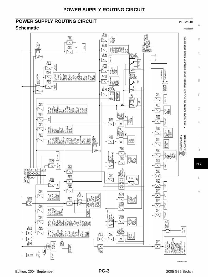
POWER SUPPLY ROUTING CIRCUIT PFP:24110
Schematic AKS000CM
TKWM2137E
PG-4
POWER SUPPLY ROUTING CIRCUIT
Edition; 2004 September 2005 G35 Sedan
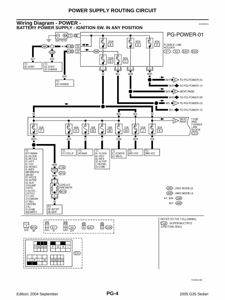
Wiring Diagram - POWER - AKS000CN
BATTERY POWER SUPPLY - IGNITION SW. IN ANY POSITION
TKWM2138E

POWER SUPPLY ROUTING CIRCUIT
PG-5
C
D
E
F
G
H
I
J
L
M
A
B
PG
Edition; 2004 September 2005 G35 Sedan
TKWM2139E

PG-6
POWER SUPPLY ROUTING CIRCUIT
Edition; 2004 September 2005 G35 Sedan
TKWM2140E

POWER SUPPLY ROUTING CIRCUIT
PG-7
C
D
E
F
G
H
I
J
L
M
A
B
PG
Edition; 2004 September 2005 G35 Sedan
TKWT1570E
PG-8
POWER SUPPLY ROUTING CIRCUIT
Edition; 2004 September 2005 G35 Sedan
TKWM2141E

POWER SUPPLY ROUTING CIRCUIT
PG-9
C
D
E
F
G
H
I
J
L
M
A
B
PG
Edition; 2004 September 2005 G35 Sedan
ACCESSORY POWER SUPPLY - IGNITION SW. IN “ACC” OR “ON”
TKWM2142E

PG-10
POWER SUPPLY ROUTING CIRCUIT
Edition; 2004 September 2005 G35 Sedan
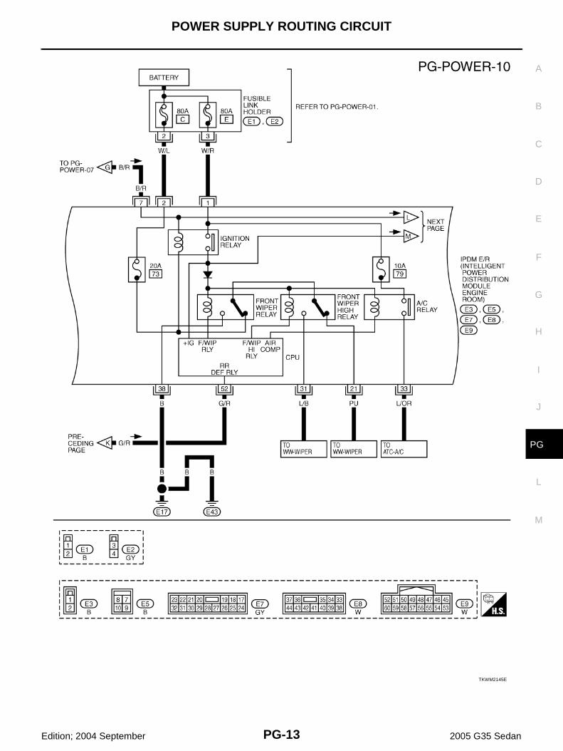
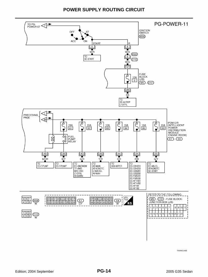
IGNITION POWER SUPPLY - IGNITION SW. IN “ON” AND/OR “START”
TKWM2143E
POWER SUPPLY ROUTING CIRCUIT
PG-11
C
D
E
F
G
H
I
J
L
M
A
B
PG
Edition; 2004 September 2005 G35 Sedan
TKWM2144E

PG-12
POWER SUPPLY ROUTING CIRCUIT
Edition; 2004 September 2005 G35 Sedan
TKWT1575E
POWER SUPPLY ROUTING CIRCUIT
PG-13
C
D
E
F
G
H
I
J
L
M
A
B
PG
Edition; 2004 September 2005 G35 Sedan
TKWM2145E
PG-14
POWER SUPPLY ROUTING CIRCUIT
Edition; 2004 September 2005 G35 Sedan
TKWM2146E

POWER SUPPLY ROUTING CIRCUIT
PG-15
C
D
E
F
G
H
I
J
L
M
A
B
PG
Edition; 2004 September 2005 G35 Sedan
Fuse AKS000I8
● If fuse is blown, be sure to eliminate cause of malfunction beforeinstalling new fuse.
● Use fuse of specified rating. Never use fuse of more than speci-fied rating.
● Do not partially install fuse; always insert it into fuse holder prop-erly.
● Remove fuse for “ELECTRICAL PARTS (BAT)” if vehicle is notused for a long period of time.
Fusible Link AKS000I9
A melted fusible link can be detected either by visual inspection or byfeeling with finger tip. If its condition is questionable, use circuittester or test lamp.CAUTION:● If fusible link should melt, it is possible that critical circuit
(power supply or large current carrying circuit) is shorted.In such a case, carefully check and eliminate cause of mal-function.
● Never wrap outside of fusible link with vinyl tape. Important:Never let fusible link touch any other wiring harness, vinylor rubber parts.
Circuit Breaker AKS000IA
The PTC thermistor generates heat in response to current flow. Thetemperature (and resistance) of the thermistor element varies withcurrent flow. Excessive current flow will cause the element's temper-ature to rise. When the temperature reaches a specified level, theelectrical resistance will rise sharply to control the circuit current.Reduced current flow will cause the element to cool. Resistance fallsaccordingly and normal circuit current flow is allowed to resume.
CEL083
CKIT0163E
SEL109W

PG-16
IPDM E/R (INTELLIGENT POWER DISTRIBUTION MODULE ENGINE ROOM)
Edition; 2004 September 2005 G35 Sedan
IPDM E/R (INTELLIGENT POWER DISTRIBUTION MODULE ENGINE ROOM)PFP:284B7
System Description AKS000I0
● IPDM E/R (Intelligent Power Distribution Module Engine Room) integrates the relay box and fuse blockwhich were originally placed in engine compartment. It controls integrated relay via IPDM E/R control cir-cuit.
● IPDM E/R-integrated control circuit performs ON-OFF operation of relay, CAN communication control, oilpressure switch signal, and hood switch signal reception, etc.
● It controls operation of each electrical part via ECM, BCM and CAN communication lines.CAUTION:None of the IPDM E/R-integrated relays can be removed.
SYSTEMS CONTROLLED BY IPDM E/R1. Lamp control
Using CAN communication line, it receives signal from BCM and controls the following lamps:● Head lamps (Hi, Lo)● Parking lamps● Tail lamps● Front fog lamps
2. Wiper controlUsing CAN communication line, it receives signals from BCM and controls the front wipers.
3. Rear window defogger relay controlUsing CAN communication line, it receives signals from BCM and controls the rear window defoggerrelay.
4. A/C compressor controlUsing CAN communication line, it receives signals from ECM and controls the A/C relay.
5. Cooling fan controlUsing CAN communication line, it receives signals from ECM and controls cooling fan relay.
6. Horn controlUsing CAN communication line, it receives signals from BCM and controls horn relay.
CAN COMMUNICATION LINE CONTROLWith CAN communication, by connecting each control unit using two communication lines (CAN L-line, CANH-line), it is possible to transmit maximum amount of information with minimum wiring. Each control unit cantransmit and receive data, and reads necessary information only.1. Fail-safe control
● When CAN communication with other control units is impossible, IPDM E/R performs fail-safe control.After CAN communication recovers normally, it also returns to normal control.
● Operation of control parts by IPDM E/R during fail-safe mode is as follows:
Controlled system Fail-safe mode
Headlamp● With the ignition switch ON, the headlamp (low) is ON.
● With the ignition switch OFF, the headlamp (low) is OFF.
Tail and parking lamps● With the ignition switch ON, the tail and parking lamps is ON.
● With the ignition switch OFF, the tail and parking lamps is OFF.
Cooling fan● With the ignition switch ON, the cooling fan HI operates.
● With the ignition switch OFF, the cooling fan stops.
Front wiperUntil the ignition switch is turned off, the front wiper LO and HI remains in the same status it was in just before fail−safe control was initiated.
Rear window defogger Rear window defogger relay OFF
A/C compressor A/C compressor OFF
Front fog lamps Front fog lamp relay OFF
IPDM E/R (INTELLIGENT POWER DISTRIBUTION MODULE ENGINE ROOM)
PG-17
C
D
E
F
G
H
I
J
L
M
A
B
PG
Edition; 2004 September 2005 G35 Sedan
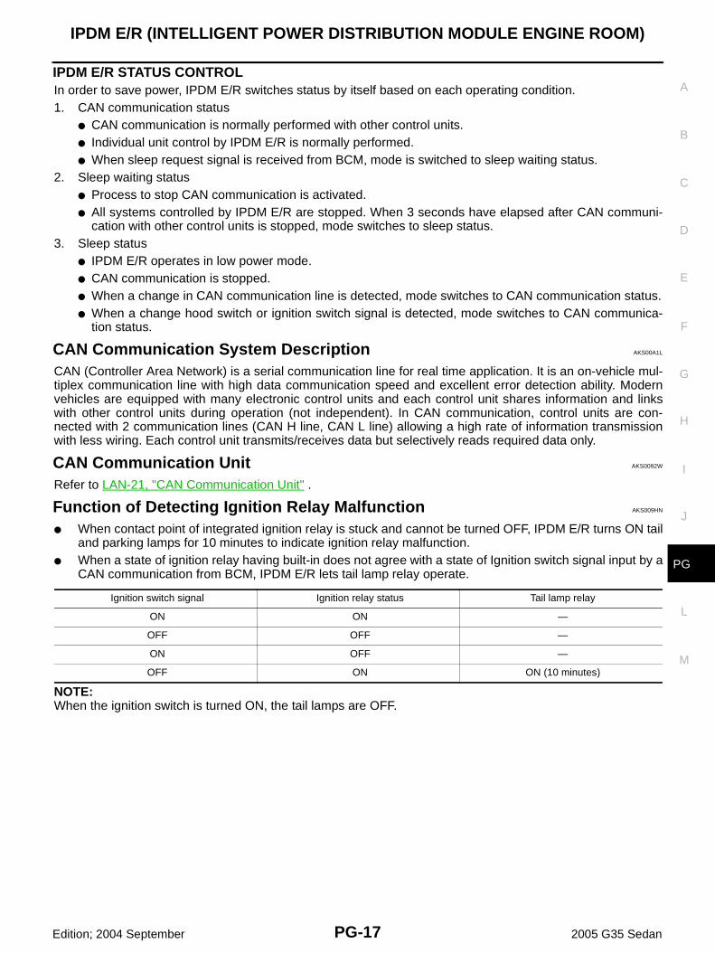
IPDM E/R STATUS CONTROLIn order to save power, IPDM E/R switches status by itself based on each operating condition.1. CAN communication status
● CAN communication is normally performed with other control units.● Individual unit control by IPDM E/R is normally performed.● When sleep request signal is received from BCM, mode is switched to sleep waiting status.
2. Sleep waiting status● Process to stop CAN communication is activated.● All systems controlled by IPDM E/R are stopped. When 3 seconds have elapsed after CAN communi-
cation with other control units is stopped, mode switches to sleep status.3. Sleep status
● IPDM E/R operates in low power mode.● CAN communication is stopped.● When a change in CAN communication line is detected, mode switches to CAN communication status.● When a change hood switch or ignition switch signal is detected, mode switches to CAN communica-
tion status.
CAN Communication System Description AKS00A1L
CAN (Controller Area Network) is a serial communication line for real time application. It is an on-vehicle mul-tiplex communication line with high data communication speed and excellent error detection ability. Modernvehicles are equipped with many electronic control units and each control unit shares information and linkswith other control units during operation (not independent). In CAN communication, control units are con-nected with 2 communication lines (CAN H line, CAN L line) allowing a high rate of information transmissionwith less wiring. Each control unit transmits/receives data but selectively reads required data only.
CAN Communication Unit AKS0092W
Refer to LAN-21, "CAN Communication Unit" .
Function of Detecting Ignition Relay Malfunction AKS009HN
● When contact point of integrated ignition relay is stuck and cannot be turned OFF, IPDM E/R turns ON tailand parking lamps for 10 minutes to indicate ignition relay malfunction.
● When a state of ignition relay having built-in does not agree with a state of Ignition switch signal input by aCAN communication from BCM, IPDM E/R lets tail lamp relay operate.
NOTE:When the ignition switch is turned ON, the tail lamps are OFF.
Ignition switch signal Ignition relay status Tail lamp relay
ON ON —
OFF OFF —
ON OFF —
OFF ON ON (10 minutes)

PG-18
IPDM E/R (INTELLIGENT POWER DISTRIBUTION MODULE ENGINE ROOM)
Edition; 2004 September 2005 G35 Sedan
CONSULT-II Function (IPDM E/R) AKS009HO
CONSULT-II can display each diagnostic item using the diagnostic test modes shown following.
CONSULT-II BASIC OPERATIONCAUTION:If CONSULT-II is used with no connection of CONSULT-II CONVERTER, malfunctions might bedetected in self-diagnosis depending on control unit which carry out CAN communication.1. With the ignition switch OFF, connect CONSULT-II and CON-
SULT-II CONVERTER to the data link connector, then turn theignition switch ON.
2. Touch “START (NISSAN BASED VHCL)”.
3. Touch “IPDM E/R” on “SELECT SYSTEM” screen.● If “IPDM E/R” is not indicated, refer to GI-38, "CONSULT-II
Data Link Connector (DLC) Circuit" .
Inspection Item, Diagnosis Mode Description
SELF-DIAG RESULTS The IPDM E/R performs diagnosis of the CAN communication and self-diagnosis.
DATA MONITOR The input/output data of the IPDM E/R is displayed in real time.
CAN DIAG SUPPORT MNTR The result of transmit/receive diagnosis of CAN communication can be read.
ACTIVE TEST The IPDM E/R sends a drive signal to electronic components to check their operation.
PIIA1095E
BCIA0029E
BCIA0030E
IPDM E/R (INTELLIGENT POWER DISTRIBUTION MODULE ENGINE ROOM)
PG-19
C
D
E
F
G
H
I
J
L
M
A
B
PG
Edition; 2004 September 2005 G35 Sedan
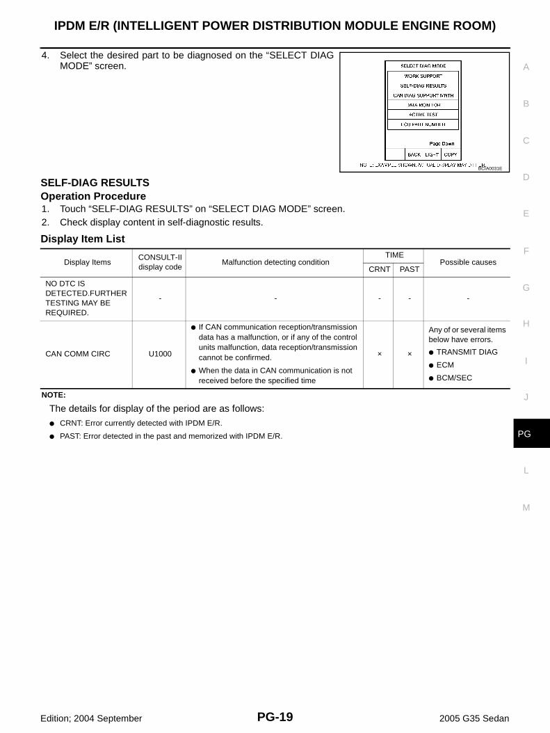
4. Select the desired part to be diagnosed on the “SELECT DIAGMODE” screen.
SELF-DIAG RESULTSOperation Procedure1. Touch “SELF-DIAG RESULTS” on “SELECT DIAG MODE” screen.2. Check display content in self-diagnostic results.
Display Item List
NOTE:
The details for display of the period are as follows:
● CRNT: Error currently detected with IPDM E/R.
● PAST: Error detected in the past and memorized with IPDM E/R.
BCIA0031E
Display ItemsCONSULT-II display code
Malfunction detecting conditionTIME
Possible causesCRNT PAST
NO DTC IS DETECTED.FURTHER TESTING MAY BE REQUIRED.
- - - - -
CAN COMM CIRC U1000
● If CAN communication reception/transmission data has a malfunction, or if any of the control units malfunction, data reception/transmission cannot be confirmed.
● When the data in CAN communication is not received before the specified time
× ×
Any of or several items below have errors.
● TRANSMIT DIAG
● ECM
● BCM/SEC
PG-20
IPDM E/R (INTELLIGENT POWER DISTRIBUTION MODULE ENGINE ROOM)
Edition; 2004 September 2005 G35 Sedan
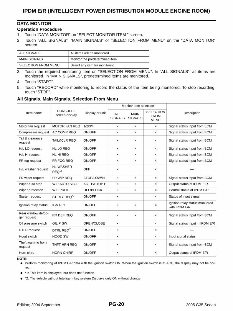
DATA MONITOROperation Procedure1. Touch “DATA MONITOR” on “SELECT MONITOR ITEM ” screen.2. Touch “ALL SIGNALS”, “MAIN SIGNALS” or “SELECTION FROM MENU” on the “DATA MONITOR”
screen.
3. Touch the required monitoring item on “SELECTION FROM MENU”. In “ALL SIGNALS”, all items aremonitored. In “MAIN SIGNALS”, predetermined items are monitored.
4. Touch “START”.5. Touch “RECORD” while monitoring to record the status of the item being monitored. To stop recording,
touch “STOP”.
All Signals, Main Signals, Selection From Menu
NOTE:● Perform monitoring of IPDM E/R data with the ignition switch ON. When the ignition switch is at ACC, the display may not be cor-
rect.
● *1: This item is displayed, but does not function.
● *2: The vehicle without Intelligent key system Displays only ON without change.
ALL SIGNALS All items will be monitored.
MAIN SIGNALS Monitor the predetermined item.
SELECTION FROM MENU Select any item for monitoring.
Item nameCONSULT-II
screen displayDisplay or unit
Monitor item selection
DescriptionALLSIGNALS
MAIN SIGNALS
SELECTION FROM MENU
Motor fan request MOTOR FAN REQ 1/2/3/4 × × × Signal status input from ECM
Compressor request AC COMP REQ ON/OFF × × × Signal status input from ECM
Tail & clearance request
TAIL&CLR REQ ON/OFF × × × Signal status input from BCM
H/L LO request HL LO REQ ON/OFF × × × Signal status input from BCM
H/L HI request HL HI REQ ON/OFF × × × Signal status input from BCM
FR fog request FR FOG REQ ON/OFF × × × Signal status input from BCM
H/L washer requestHL WASHER
REQ*1 OFF × × —
FR wiper request FR WIP REQ STOP/LOW/HI × × × Signal status input from BCM
Wiper auto stop WIP AUTO STOP ACT P/STOP P × × × Output status of IPDM E/R
Wiper protection WIP PROT OFF/BLOCK × × × Control status of IPDM E/R
Starter request ST RLY REQ*2 ON/OFF × × Status of input signal
Ignition relay status IGN RLY ON/OFF × × × Ignition relay status monitored with IPDM E/R
Rear window defog-ger request
RR DEF REQ ON/OFF × × × Signal status input from BCM
Oil pressure switch OIL P SW OPEN/CLOSE × × Signal status input in IPDM E/R
DTLR request DTRL REQ*1 ON/OFF × × —
Hood switch HOOD SW ON/OFF × × Input signal status
Theft warning horn request
THFT HRN REQ ON/OFF × × Signal status input from BCM
Horn chirp HORN CHIRP ON/OFF × × Output status of IPDM E/R

IPDM E/R (INTELLIGENT POWER DISTRIBUTION MODULE ENGINE ROOM)
PG-21
C
D
E
F
G
H
I
J
L
M
A
B
PG
Edition; 2004 September 2005 G35 Sedan
ACTIVE TESTOperation Procedure1. Touch “ACTIVE TEST” on “SELECT DIAG MODE” screen.2. Touch item to be tested.3. Touch “START”, and confirm its operation.4. Touch “STOP” while testing to stop the operation.
NOTE:This item is displayed, but cannot be tested.
Test item CONSULT-II screen display Description
Tail lamp operation TAIL LAMP With a certain ON-OFF operation, the tail lamp relay can be operated.
Rear window defogger oper-ation
REAR DEFOGGERWith a certain ON-OFF operation, the rear window defogger relay can be operated.
Front wiper (HI, LO) opera-tion
FRONT WIPERWith a certain operation (OFF, HI ON, LO ON), the front wiper relay (Lo, Hi) can be operated.
Cooling fan operation MOTOR FAN With a certain operation (1,2,3,4), the cooling fan can be operated.
Headlamp washer operation HEAD LAMP WASHERNOTE —
Lamp (HI, LO, FOG) opera-tion
LAMPSWith a certain operation (OFF, HI ON, LO ON, FOG ON), the lamp relay (Lo, Hi, Fog) can be operated.
Horn operation HORN Push “ON” button, horn relay operates 20ms.
PG-22
IPDM E/R (INTELLIGENT POWER DISTRIBUTION MODULE ENGINE ROOM)
Edition; 2004 September 2005 G35 Sedan
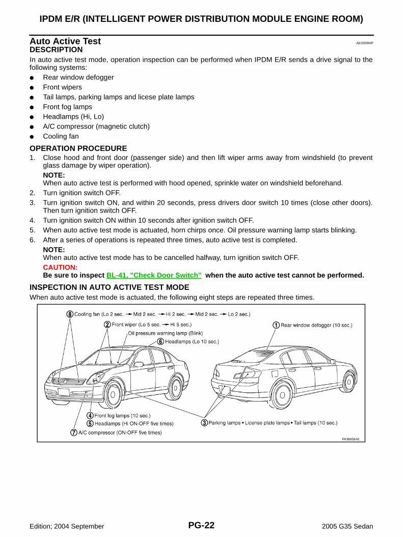
Auto Active Test AKS009HP
DESCRIPTIONIn auto active test mode, operation inspection can be performed when IPDM E/R sends a drive signal to thefollowing systems:● Rear window defogger● Front wipers● Tail lamps, parking lamps and licese plate lamps● Front fog lamps● Headlamps (Hi, Lo)● A/C compressor (magnetic clutch)● Cooling fan
OPERATION PROCEDURE1. Close hood and front door (passenger side) and then lift wiper arms away from windshield (to prevent
glass damage by wiper operation).NOTE:When auto active test is performed with hood opened, sprinkle water on windshield beforehand.
2. Turn ignition switch OFF.3. Turn ignition switch ON, and within 20 seconds, press drivers door switch 10 times (close other doors).
Then turn ignition switch OFF.4. Turn ignition switch ON within 10 seconds after ignition switch OFF. 5. When auto active test mode is actuated, horn chirps once. Oil pressure warning lamp starts blinking.6. After a series of operations is repeated three times, auto active test is completed.
NOTE:When auto active test mode has to be cancelled halfway, turn ignition switch OFF.CAUTION:Be sure to inspect BL-41, "Check Door Switch" when the auto active test cannot be performed.
INSPECTION IN AUTO ACTIVE TEST MODEWhen auto active test mode is actuated, the following eight steps are repeated three times.
PKIB6584E

IPDM E/R (INTELLIGENT POWER DISTRIBUTION MODULE ENGINE ROOM)
PG-23
C
D
E
F
G
H
I
J
L
M
A
B
PG
Edition; 2004 September 2005 G35 Sedan
Concept of Auto Active Test● IPDM E/R actuates auto active test mode when it receives door switch signal from BCM via CAN commu-
nication line. Therefore, when auto active test mode is activated successfully, CAN communicationbetween IPDM E/R and BCM is normal.
● If any of systems controlled by IPDM E/R cannot be operated, possible cause can be easily diagnosedusing auto active test.
Diagnosis chart in auto active test mode
Symptom Inspection contents Possible cause
Rear window defog-ger does not operate.
Perform auto active test. Does rear win-dow defogger oper-ate?
YES ● BCM signal input circuit malfunction
NO
● Rear window defogger relay malfunction
● Harness/connector malfunction between IPDM E/R and rear window defogger relay
● Open circuit of rear window defogger
● IPDM E/R malfunction
Any of front wipers, tail and parking lamps, front fog lamps, and head lamps (Hi, Lo) do not operate.
Perform auto active test. Does system in question oper-ate?
YES ● BCM signal input system malfunction
NO
● Lamp/wiper motor malfunction
● Lamp/wiper motor ground circuit malfunction
● Harness/connector malfunction between IPDM E/R and system in question
● IPDM E/R (integrated relay) malfunction
A/C compressor does not operate.
Perform auto active test. Does magnetic clutch operate?
YES
● BCM signal input circuit malfunction
● CAN communication signal between BCM and ECM.
● CAN communication signal between ECM and IPDM E/R
NO
● Magnetic clutch malfunction
● Harness/connector malfunction between IPDM E/R and magnetic clutch
● IPDM E/R (integrated relay) malfunction
Cooling fan does not operate.
Perform auto active test. Does cooling fan operate?
YES● ECM signal input circuit
● CAN communication signal between ECM and IPDM E/R
NO
● Cooling fan motor malfunction
● Harness/connector malfunction between IPDM E/R and cooling fan motor
● IPDM E/R (integrated relay) malfunction
Oil pressure warning lamp does not oper-ate.
Perform auto active test. Does oil pres-sure warning lamp blink?
YES
● Harness/connector malfunction between IPDM E/R and oil pressure switch
● Oil pressure switch malfunction
● IPDM E/R malfunction
NO● CAN communication signal between IPDM E/R and combination meter
● Combination meter

PG-24
IPDM E/R (INTELLIGENT POWER DISTRIBUTION MODULE ENGINE ROOM)
Edition; 2004 September 2005 G35 Sedan
Schematic AKS009HQ
TKWM2147E
IPDM E/R (INTELLIGENT POWER DISTRIBUTION MODULE ENGINE ROOM)
PG-25
C
D
E
F
G
H
I
J
L
M
A
B
PG
Edition; 2004 September 2005 G35 Sedan
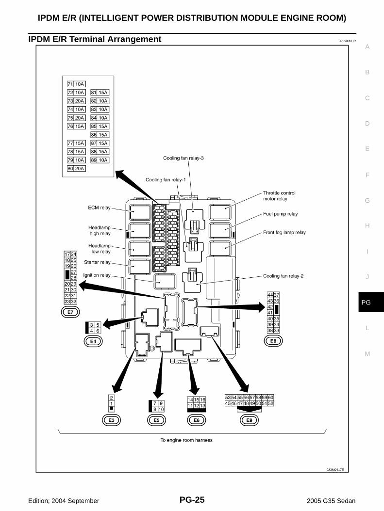
IPDM E/R Terminal Arrangement AKS009HR
CKIM0417E
PG-26
IPDM E/R (INTELLIGENT POWER DISTRIBUTION MODULE ENGINE ROOM)
Edition; 2004 September 2005 G35 Sedan
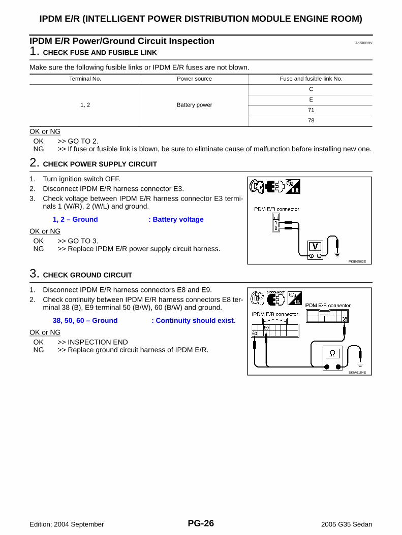
IPDM E/R Power/Ground Circuit Inspection AKS009HV
1. CHECK FUSE AND FUSIBLE LINK
Make sure the following fusible links or IPDM E/R fuses are not blown.
OK or NGOK >> GO TO 2.NG >> If fuse or fusible link is blown, be sure to eliminate cause of malfunction before installing new one.
2. CHECK POWER SUPPLY CIRCUIT
1. Turn ignition switch OFF.2. Disconnect IPDM E/R harness connector E3.3. Check voltage between IPDM E/R harness connector E3 termi-
nals 1 (W/R), 2 (W/L) and ground.
OK or NGOK >> GO TO 3.NG >> Replace IPDM E/R power supply circuit harness.
3. CHECK GROUND CIRCUIT
1. Disconnect IPDM E/R harness connectors E8 and E9.2. Check continuity between IPDM E/R harness connectors E8 ter-
minal 38 (B), E9 terminal 50 (B/W), 60 (B/W) and ground.
OK or NGOK >> INSPECTION ENDNG >> Replace ground circuit harness of IPDM E/R.
Terminal No. Power source Fuse and fusible link No.
1, 2 Battery power
C
E
71
78
1, 2 – Ground : Battery voltage
PKIB6562E
38, 50, 60 – Ground : Continuity should exist.
SKIA6184E

IPDM E/R (INTELLIGENT POWER DISTRIBUTION MODULE ENGINE ROOM)
PG-27
C
D
E
F
G
H
I
J
L
M
A
B
PG
Edition; 2004 September 2005 G35 Sedan
Inspection With CONSULT-II (Self-Diagnosis) AKS009HW
CAUTION:If CONSULT-II is used with no connection of CONSULT-II CONVERTER, malfunctions might bedetected in self-diagnosis depending on control unit which carry out CAN communication.
1. CHECK SELF DIAGNOSTIC RESULT
1. Connect CONSULT-II and select “IPDM E/R” on the “SELECT SYSTEM” screen.2. Select “SELF-DIAG RESULTS” on the “SELECT DIAG MODE” screen.3. Check display content in self diagnostic results.
NOTE:The details for display of the period are as follows:
● CRNT: Error currently detected with IPDM E/R.
● PAST: Error detected in the past and memorized with IPDM E/R.
Contents displayedNO DTC IS DETECTED.FURTHER TESTING MAY BE REQUIRED.>>INSPECTION ENDCAN COMM CIRC>>After print-out of the monitor items, refer to LAN-3, "Precautions When Using CON-
SULT-II" .
CONSULT-II displayCONSULT-II display code
TIMEDetails of diagnosis result
CRNT PAST
NO DTC IS DETECTED.FURTHER TESTING MAY BE REQUIRED.
- - - No malfunction
CAN COMM CIRC U1000 × ×
Any of or several items below have errors.
● TRANSMIT DIAG
● ECM
● BCM/SEC
PG-28
IPDM E/R (INTELLIGENT POWER DISTRIBUTION MODULE ENGINE ROOM)
Edition; 2004 September 2005 G35 Sedan
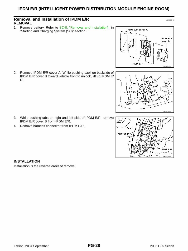
Removal and Installation of IPDM E/R AKS009HX
REMOVAL1. Remove battery. Refer to SC-8, "Removal and Installation" in
“Starting and Charging System (SC)” section.
2. Remove IPDM E/R cover A. While pushing pawl on backside ofIPDM E/R cover B toward vehicle front to unlock, lift up IPDM E/R.
3. While pushing tabs on right and left side of IPDM E/R, removeIPDM E/R cover B from IPDM E/R.
4. Remove harness connector from IPDM E/R.
INSTALLATIONInstallation is the reverse order of removal.
SKIA0793E
SKIA1902E
SKIA1904E

GROUND
PG-29
C
D
E
F
G
H
I
J
L
M
A
B
PG
Edition; 2004 September 2005 G35 Sedan
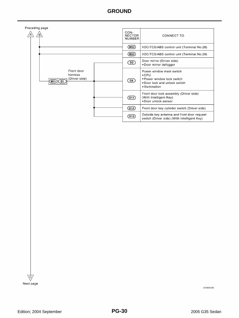
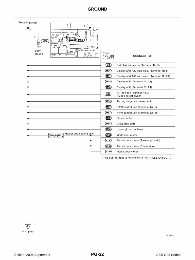
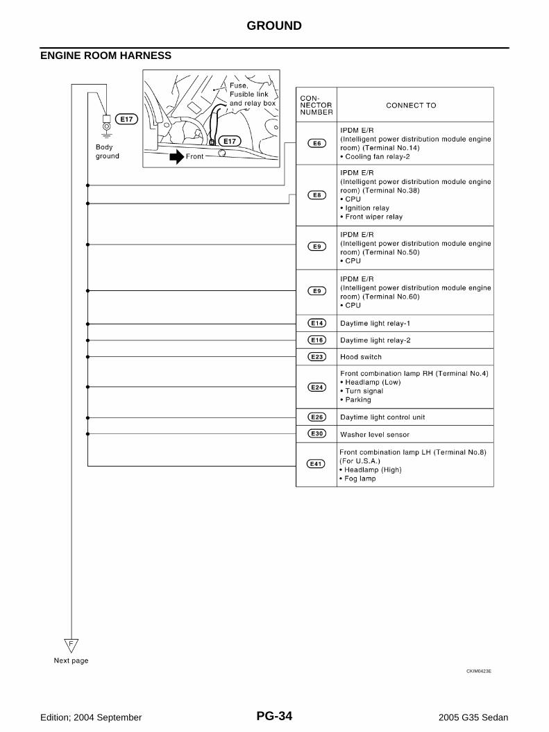
GROUND PFP:00011
Ground Distribution AKS000IB
MAIN HARNESS
CKIM0418E
PG-30
GROUND
Edition; 2004 September 2005 G35 Sedan
CKIM0419E

GROUND
PG-31
C
D
E
F
G
H
I
J
L
M
A
B
PG
Edition; 2004 September 2005 G35 Sedan
CKIM0420E
PG-32
GROUND
Edition; 2004 September 2005 G35 Sedan
CKIM0421E

GROUND
PG-33
C
D
E
F
G
H
I
J
L
M
A
B
PG
Edition; 2004 September 2005 G35 Sedan
CKIM0422E
PG-34
GROUND
Edition; 2004 September 2005 G35 Sedan
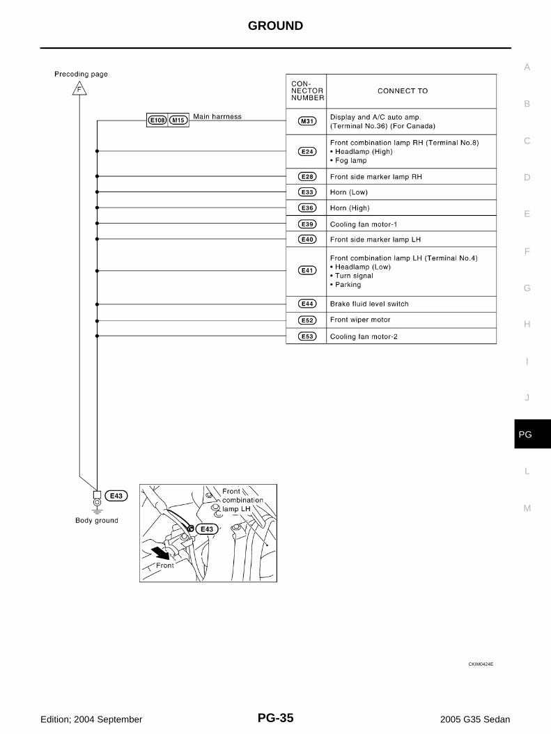
ENGINE ROOM HARNESS
CKIM0423E
GROUND
PG-35
C
D
E
F
G
H
I
J
L
M
A
B
PG
Edition; 2004 September 2005 G35 Sedan
CKIM0424E

PG-36
GROUND
Edition; 2004 September 2005 G35 Sedan
CKIT0446E

GROUND
PG-37
C
D
E
F
G
H
I
J
L
M
A
B
PG
Edition; 2004 September 2005 G35 Sedan
ENGINE CONTROL HARNESS
CKIT0486E
PG-38
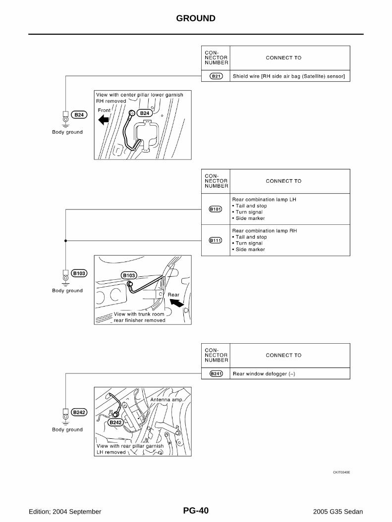
GROUND
Edition; 2004 September 2005 G35 Sedan
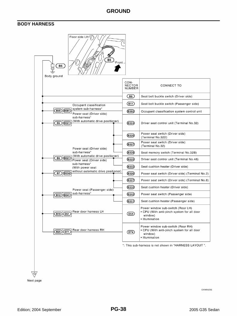
BODY HARNESS
CKIM0425E

GROUND
PG-39
C
D
E
F
G
H
I
J
L
M
A
B
PG
Edition; 2004 September 2005 G35 Sedan
CKIM0426E
PG-40
GROUND
Edition; 2004 September 2005 G35 Sedan
CKIT0340E

HARNESS
PG-41
C
D
E
F
G
H
I
J
L
M
A
B
PG
Edition; 2004 September 2005 G35 Sedan
HARNESS PFP:00011
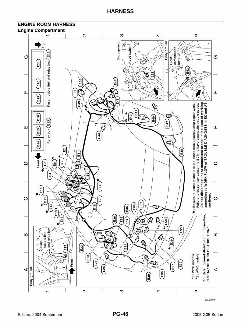
Harness Layout AKS000IC
HOW TO READ HARNESS LAYOUTThe following Harness Layouts use a map style grid to help locateconnectors on the figures:● Main Harness● Engine Room Harness (Engine Compartment)● Engine Control Harness● Body Harness (Passenger Compartment)
To Use the Grid Reference1. Find the desired connector number on the connector list.2. Find the grid reference.3. On the figure, find the crossing of the grid reference letter column and number row.4. Find the connector number in the crossing zone.5. Follow the line (if used) to the connector.CONNECTOR SYMBOLMain symbols of connector (in Harness Layout) are indicated in the below.
SEL252V
CKIT0108E
PG-42
HARNESS
Edition; 2004 September 2005 G35 Sedan
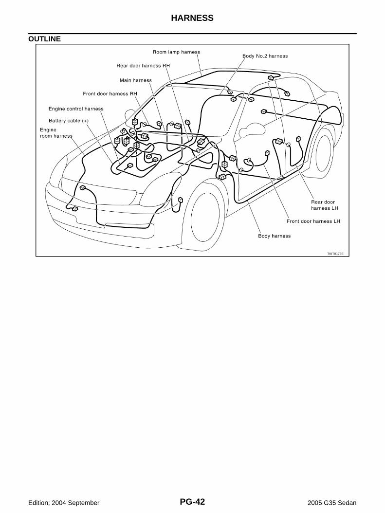
OUTLINE
TKIT0179E

HARNESS
PG-43
C
D
E
F
G
H
I
J
L
M
A
B
PG
Edition; 2004 September 2005 G35 Sedan
MAIN HARNESS
TKIM0305E

PG-44
HARNESS
Edition; 2004 September 2005 G35 Sedan
TKIM0306E

HARNESS
PG-45
C
D
E
F
G
H
I
J
L
M
A
B
PG
Edition; 2004 September 2005 G35 Sedan
TKIM0307E
PG-46
HARNESS
Edition; 2004 September 2005 G35 Sedan
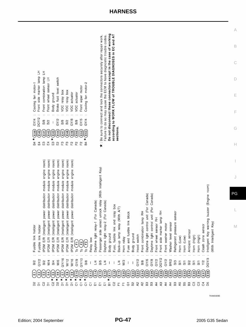
ENGINE ROOM HARNESSEngine Compartment
TKIM0308E
HARNESS
PG-47
C
D
E
F
G
H
I
J
L
M
A
B
PG
Edition; 2004 September 2005 G35 Sedan
TKIM0309E

PG-48
HARNESS
Edition; 2004 September 2005 G35 Sedan
Passenger Compartment
TKIM0310E

HARNESS
PG-49
C
D
E
F
G
H
I
J
L
M
A
B
PG
Edition; 2004 September 2005 G35 Sedan
Battery Cable (2WD)
TKIT0031E
PG-50
HARNESS
Edition; 2004 September 2005 G35 Sedan
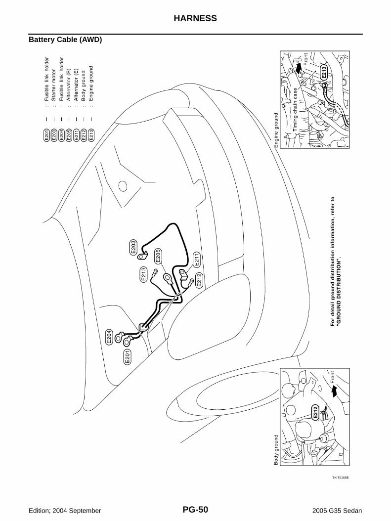
Battery Cable (AWD)
TKIT0269E
HARNESS
PG-51
C
D
E
F
G
H
I
J
L
M
A
B
PG
Edition; 2004 September 2005 G35 Sedan
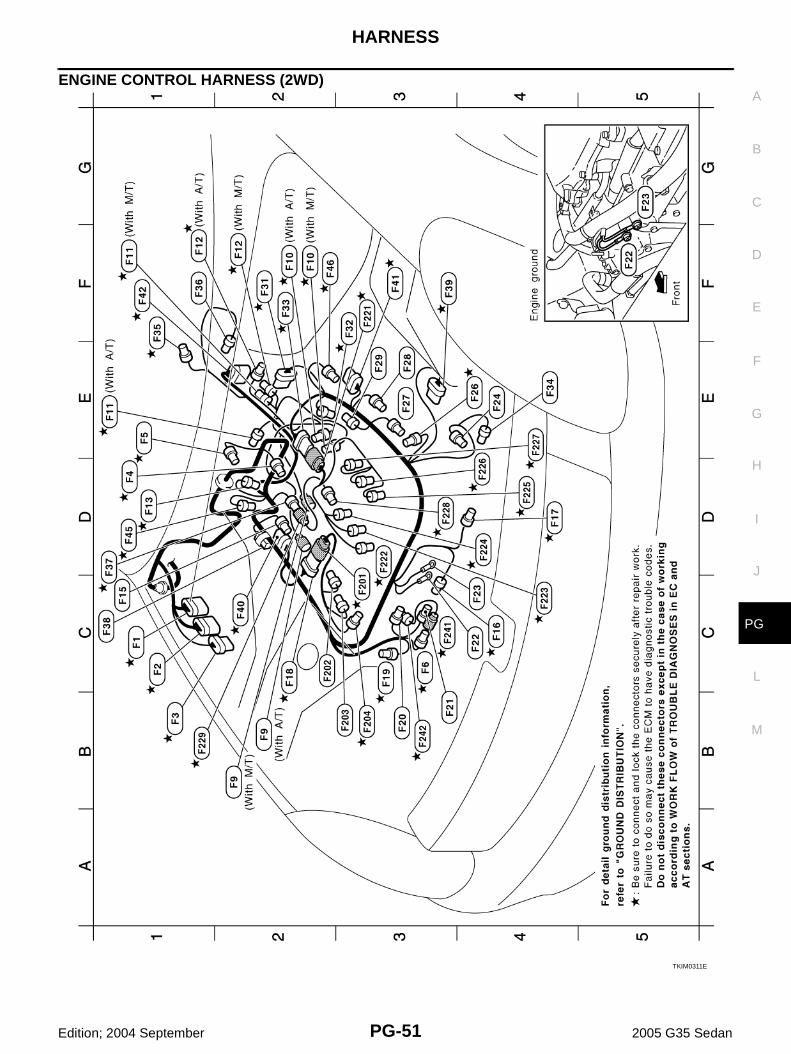
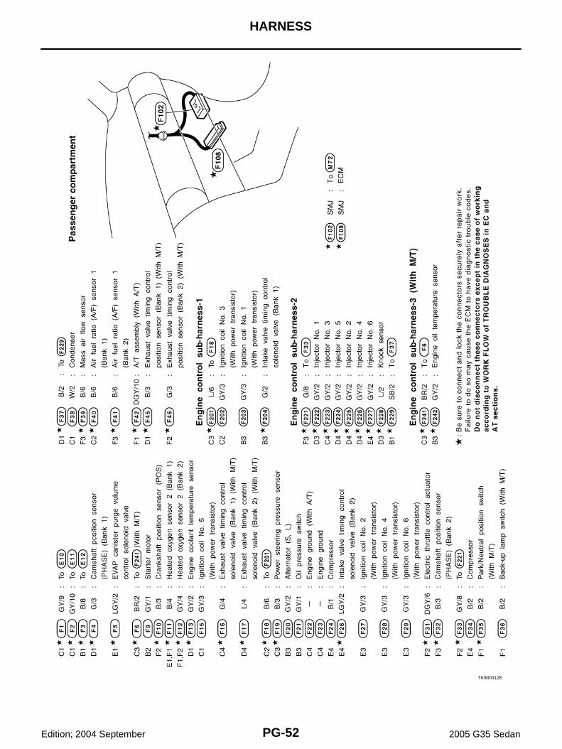
ENGINE CONTROL HARNESS (2WD)
TKIM0311E
PG-52
HARNESS
Edition; 2004 September 2005 G35 Sedan
TKIM0312E

HARNESS
PG-53
C
D
E
F
G
H
I
J
L
M
A
B
PG
Edition; 2004 September 2005 G35 Sedan
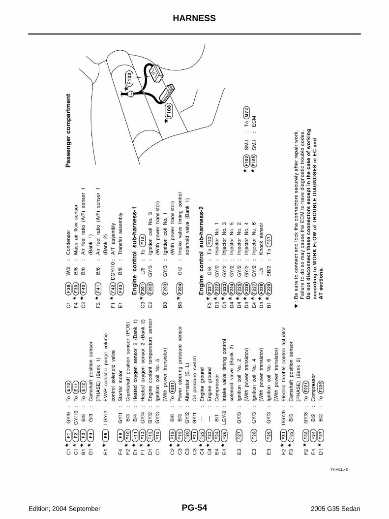
ENGINE CONTROL HARNESS (AWD)
TKIM0313E
PG-54
HARNESS
Edition; 2004 September 2005 G35 Sedan
TKIM0314E

HARNESS
PG-55
C
D
E
F
G
H
I
J
L
M
A
B
PG
Edition; 2004 September 2005 G35 Sedan
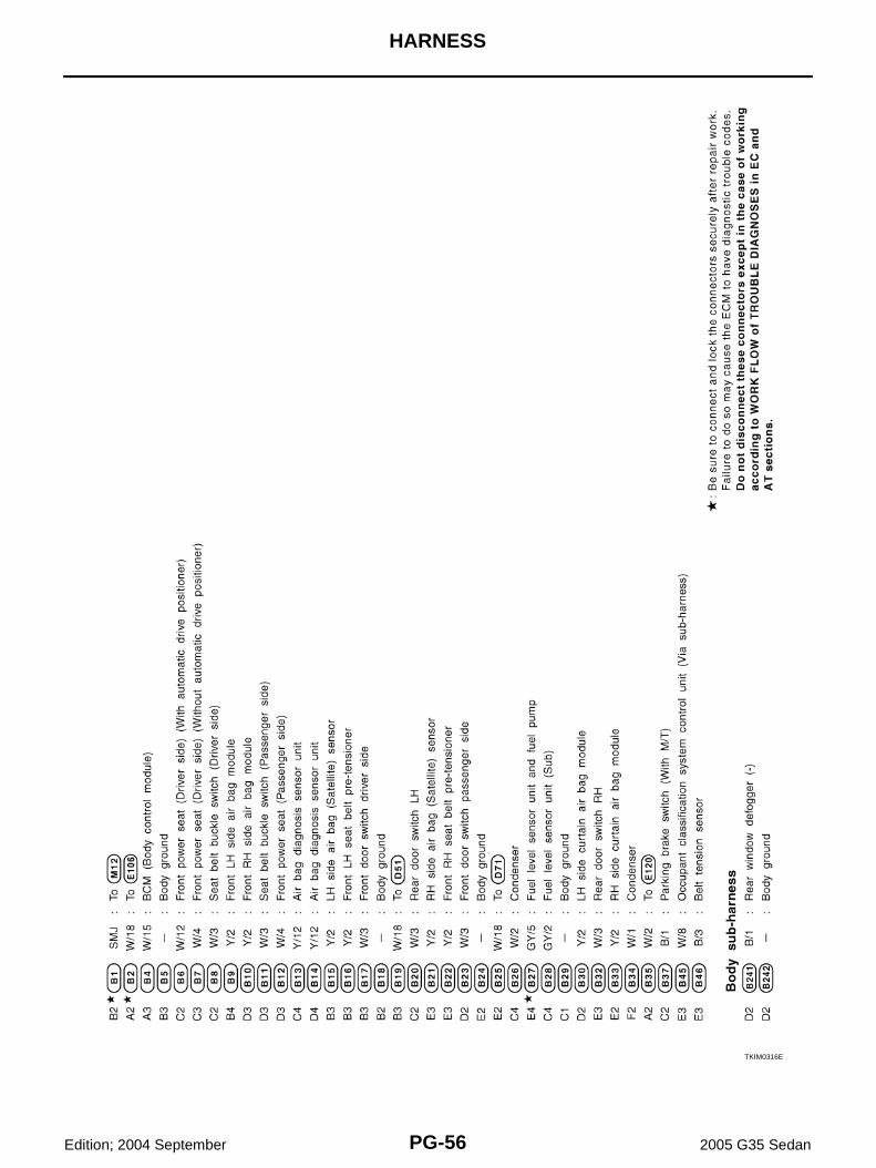
BODY HARNESSPassenger Compartment
TKIM0315E
PG-56
HARNESS
Edition; 2004 September 2005 G35 Sedan
TKIM0316E

HARNESS
PG-57
C
D
E
F
G
H
I
J
L
M
A
B
PG
Edition; 2004 September 2005 G35 Sedan
Trunk Room
TKIM0317E

PG-58
HARNESS
Edition; 2004 September 2005 G35 Sedan
BODY NO. 2 HARNESS
TKIT0098E
HARNESS
PG-59
C
D
E
F
G
H
I
J
L
M
A
B
PG
Edition; 2004 September 2005 G35 Sedan
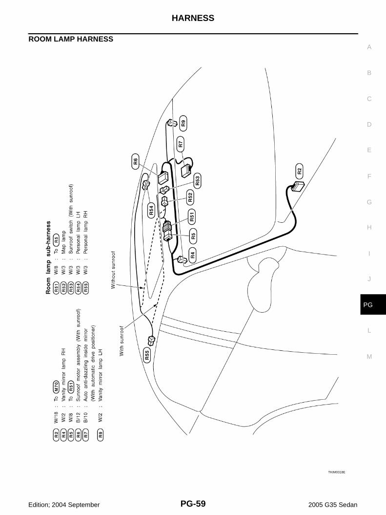
ROOM LAMP HARNESS
TKIM0318E
PG-60
HARNESS
Edition; 2004 September 2005 G35 Sedan
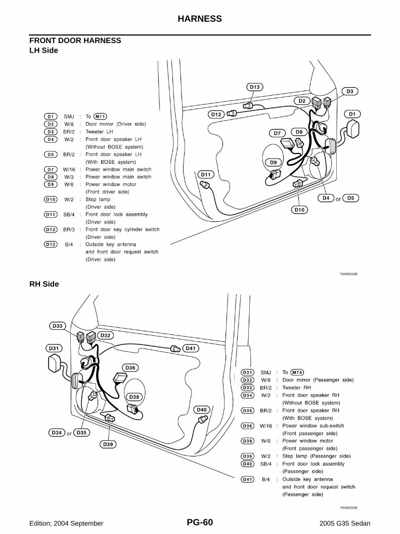
FRONT DOOR HARNESS LH Side
RH SideTKIM0319E
TKIM0320E
HARNESS
PG-61
C
D
E
F
G
H
I
J
L
M
A
B
PG
Edition; 2004 September 2005 G35 Sedan
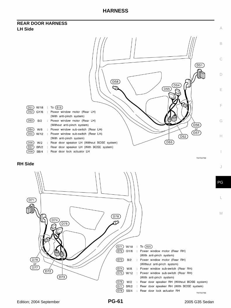
REAR DOOR HARNESSLH Side
RH SideTKIT0275E
TKIT0276E

PG-62
HARNESS
Edition; 2004 September 2005 G35 Sedan
Wiring Diagram Codes (Cell Codes) AKS000ID
Use the chart below to find out what each wiring diagram code stands for.Refer to the wiring diagram code in the alphabetical index to find the location (page number) of each wiringdiagram.
Code Section Wiring Diagram Name
A/C ATC Air Conditioner
AF1B1 EC Air Fuel Ratio Sensor 1 Bank 1
AF1B2 EC Air Fuel Ratio Sensor 1 Bank 2
AF1HB1 EC Air Fuel Ratio Sensor 1 Heater Bank 1
AF1HB2 EC Air Fuel Ratio Sensor 1 Heater Bank 2
APPS1 EC Accelerator Pedal Position Sensor
APPS2 EC Accelerator Pedal Position Sensor
APPS3 EC Accelerator Pedal Position Sensor
ASC/BS EC Automatic Speed Control Device (ASCD) Brake Switch
ASC/SW EC Automatic Speed Control Device (ASCD) Steering Switch
ASCBOF EC Automatic Speed Control Device (ASCD) Brake Switch
ASCIND EC Automatic Speed Control Device (ASCD) Indicator
AT/IND DI A/T Indicator Lamp
AUDIO AV Audio
AUT/DP SE Automatic Drive Positioner
AUTO/L LT Automatic Light System
AWD TF AWD Control System
BACK/L LT Back-Up Lamp
BRK/SW EC Brake Switch
CAN AT CAN Communication Line
CAN EC CAN Communication Line
CAN LAN CAN System
CHARGE SC Charging System
CHIME DI Warning Chime
CIGAR WW Cigarette Lighter
CLOCK DI Clock
COMBSW LT Combination Switch
COMM AV Audio Visual Communication Line
COMPAS DI Compass and Thermometer
COOL/F EC Cooling Fan Control
D/LOCK BL Power Door Lock
DEF GW Rear Window Defogger
DTRL LT Headlamp - With Daytime Light System
ECM/PW EC ECM Power Supply for Back-Up
ECTS EC Engine Coolant Temperature Sensor
EOTS EC Engine Oil Temperatuer Sensor
ETC1 EC Electric Throttle Control Function
ETC2 EC Electric Throttle Control Motor Relay
ETC3 EC Electric Throttle Control Motor
EVCB1 EC Exhaust Valve Timing Control Solenoid Valve (Bank 1)
EVCB2 EC Exhaust Valve Timing Control Solenoid Valve (Bank 2)

HARNESS
PG-63
C
D
E
F
G
H
I
J
L
M
A
B
PG
Edition; 2004 September 2005 G35 Sedan
EVCSB1 EC Exhaust Valve Timing Control Position Sensor (Bank 1)
EVCSB2 EC Exhaust Valve Timing Control Position Sensor (Bank 2)
F/FOG LT Front Fog Lamp
F/PUMP EC Fuel Pump
FTS AT A/T Fluid Temperature Sensor Circuit
FTTS EC Fuel Tank Temperature Sensor
FUELB1 EC Fuel Injection System Function (Bank 1)
FUELB2 EC Fuel Injection System Function (Bank 2)
H/LAMP LT Headlamp
HORN WW Horn
HSEAT SE Heated Seat
I/KEY BL Intelligent Key System
I/MIRR GW Inside Mirror (Auto Anti-Dazzling Mirror)
IATS EC Intake Air Temperature Sensor
IGNSYS EC Ignition System
ILL LT Illumination
INJECT EC Injector
IVCB1 EC Intake Valve Timing Control Solenoid Valve Bank 1
IVCB2 EC Intake Valve Timing Control Solenoid Valve Bank 2
KEYLES BL Remote Keyless Entry System
KS EC Knock Sensor
MAFS EC Mass Air Flow Sensor
MAIN AT Main Power Supply and Ground Circuit
MAIN EC Main Power Supply and Ground Circuit
METER DI Speedometer, Tachometer, Temp. and Fuel Gauges
MIL/DL EC MIL & Data Link Connector
MIRROR GW Door Mirror
MMSW AT Manual Mode Switch
NATS BL Nissan Anti-Theft System
NAVI AV Navigation System
NONDTC AT Non-Detective Items
O2H2B1 EC Heated Oxygen Sensor 2 Heater Bank 1
O2H2B2 EC Heated Oxygen Sensor 2 Heater Bank 2
O2S2B1 EC Heated Oxygen Sensor 2 Bank 1
O2S2B2 EC Heated Oxygen Sensor 2 Bank 2
P/SCKT WW Power Socket
PGC/V EC EVAP Canister Purge Volume Control Solenoid Valve
PHSB1 EC Camshaft Position Sensor (PHASE) (Bank 1)
PHSB2 EC Camshaft Position Sensor (PHASE) (Bank 2)
PNP/SW AT Park/Neutral Position Switch
PNP/SW EC Park/Neutral Position Switch
POS EC Crankshaft Position Sensor (CKPS) (POS)
POWER PG Power Supply Routing
PRE/SE EC EVAP Control System Pressure Sensor
Code Section Wiring Diagram Name

PG-64
HARNESS
Edition; 2004 September 2005 G35 Sedan
PS/SEN EC Power Steering Pressure Sensor
ROOM/L LT Interior Room Lamp
RP/SEN EC Refrigerant Pressure Sensor
SEAT SE Power Seat
SEN/PW EC Sensor Power Supply
SHIFT AT A/T Shift Lock System
SNOWSW EC Snow Mode Switch
SROOF RF Sunroof
SRS SRS Supplemental Restraint System
START SC Starting System
STOP/L LT Stop Lamp
STSIG AT Start Signal Circuit
T/WARN WT Low Tire Pressure Warning System
TAIL/L LT Parking, License and Tail Lamps
TLID BL Trunk Lid Opener
TPS1 EC Throttle Position Sensor (Sensor 1)
TPS2 EC Throttle Position Sensor (Sensor 2)
TPS3 EC Throttle Position Sensor
TRNSCV BL Homelink Universal Transceiver
TURN LT Turn Signal and Hazard Warning Lamp
VDC BRC Vehicle Dynamics Control System
VEHSEC BL Vehicle Security System
VENT/V EC EVAP Canister Vent Control Valve
VSSA/T AT Vehicle speed Sensor A/T (Revolution Sensor)
W/ANT AV Audio Antenna
WARN DI Warning Lamps
WINDOW GW Power Window
WIPER WW Front Wiper and Washer
Code Section Wiring Diagram Name
ELECTRICAL UNITS LOCATION
PG-65
C
D
E
F
G
H
I
J
L
M
A
B
PG
Edition; 2004 September 2005 G35 Sedan
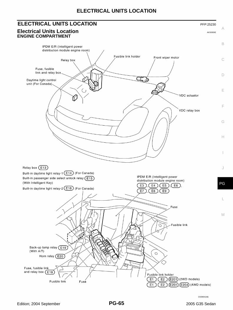
ELECTRICAL UNITS LOCATION PFP:25230
Electrical Units Location AKS000IE
ENGINE COMPARTMENT
CKIM0416E

PG-66
ELECTRICAL UNITS LOCATION
Edition; 2004 September 2005 G35 Sedan
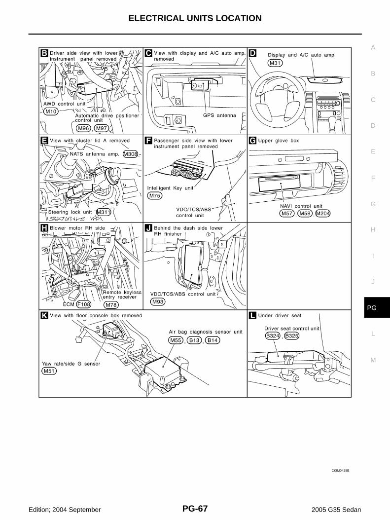
PASSENGER COMPARTMENT
CKIM0427E
ELECTRICAL UNITS LOCATION
PG-67
C
D
E
F
G
H
I
J
L
M
A
B
PG
Edition; 2004 September 2005 G35 Sedan
CKIM0428E
PG-68
ELECTRICAL UNITS LOCATION
Edition; 2004 September 2005 G35 Sedan
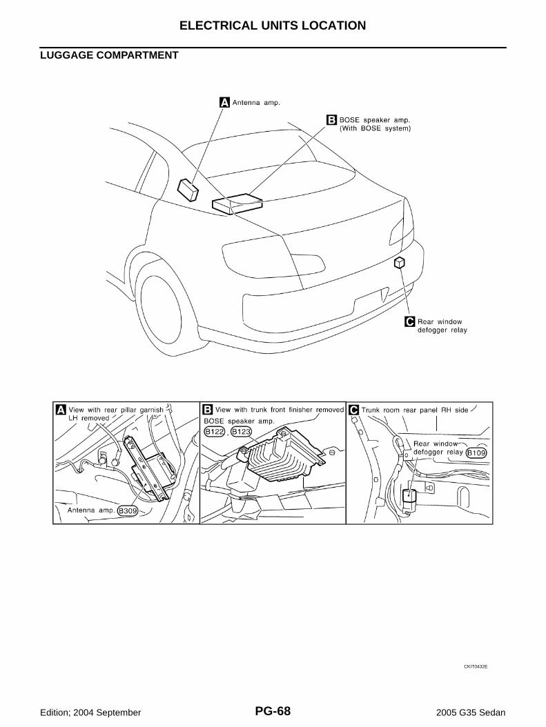
LUGGAGE COMPARTMENT
CKIT0432E
HARNESS CONNECTOR
PG-69
C
D
E
F
G
H
I
J
L
M
A
B
PG
Edition; 2004 September 2005 G35 Sedan
HARNESS CONNECTOR PFP:00011
Description AKS000IF
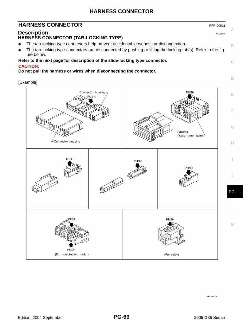
HARNESS CONNECTOR (TAB-LOCKING TYPE)● The tab-locking type connectors help prevent accidental looseness or disconnection.● The tab-locking type connectors are disconnected by pushing or lifting the locking tab(s). Refer to the fig-
ure below.Refer to the next page for description of the slide-locking type connector.CAUTION:Do not pull the harness or wires when disconnecting the connector.
[Example]
SEL769DA
PG-70
HARNESS CONNECTOR
Edition; 2004 September 2005 G35 Sedan
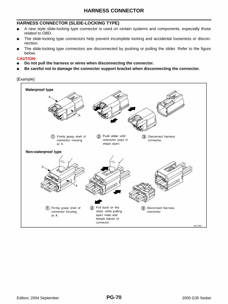
HARNESS CONNECTOR (SLIDE-LOCKING TYPE)● A new style slide-locking type connector is used on certain systems and components, especially those
related to OBD.● The slide-locking type connectors help prevent incomplete locking and accidental looseness or discon-
nection.● The slide-locking type connectors are disconnected by pushing or pulling the slider. Refer to the figure
below.CAUTION:● Do not pull the harness or wires when disconnecting the connector.● Be careful not to damage the connector support bracket when disconnecting the connector.
[Example]
SEL769V
ELECTRICAL UNITS
PG-71
C
D
E
F
G
H
I
J
L
M
A
B
PG
Edition; 2004 September 2005 G35 Sedan
ELECTRICAL UNITS PFP:00011
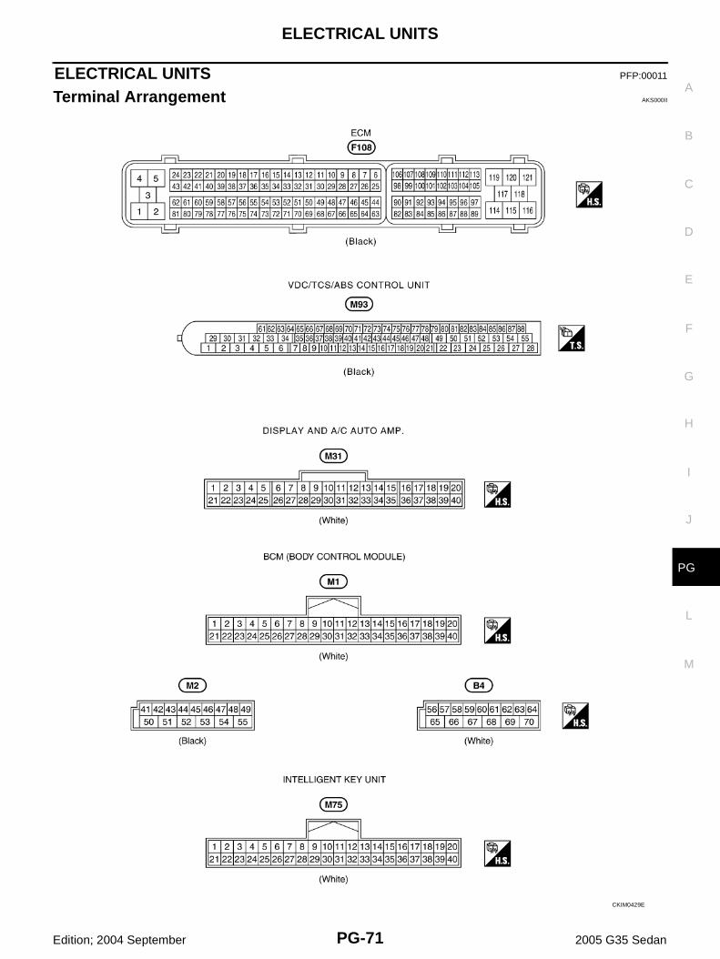
Terminal Arrangement AKS000II
CKIM0429E
PG-72
SMJ (SUPER MULTIPLE JUNCTION)
Edition; 2004 September 2005 G35 Sedan
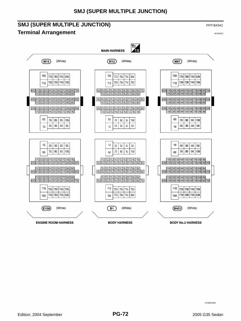
SMJ (SUPER MULTIPLE JUNCTION) PFP:B4341
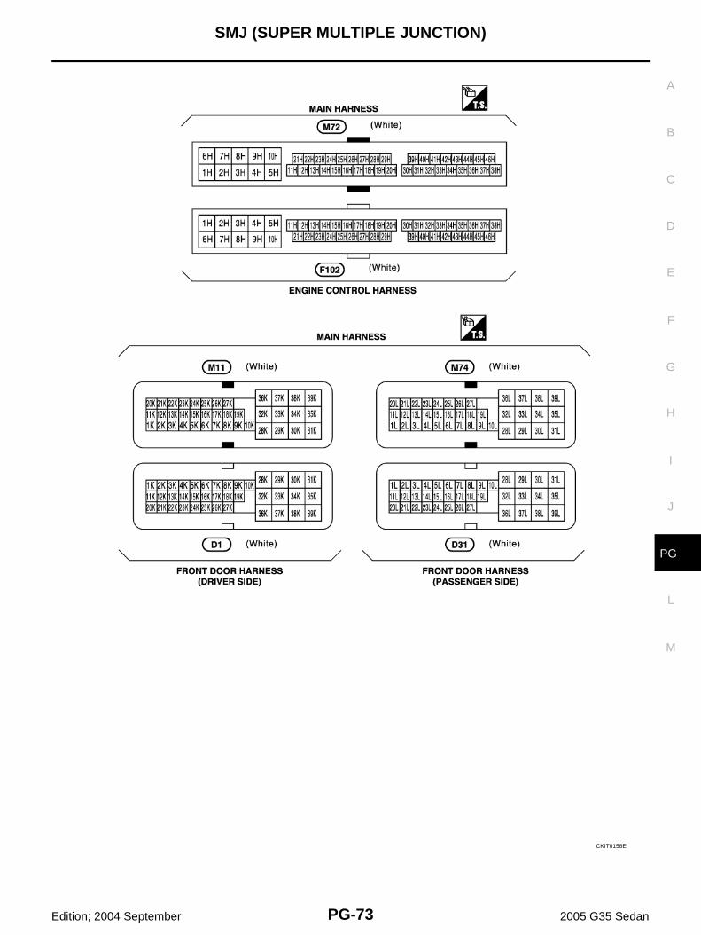
Terminal Arrangement AKS000IJ
CKIM0430E
SMJ (SUPER MULTIPLE JUNCTION)
PG-73
C
D
E
F
G
H
I
J
L
M
A
B
PG
Edition; 2004 September 2005 G35 Sedan
CKIT0158E
PG-74
STANDARDIZED RELAY
Edition; 2004 September 2005 G35 Sedan
STANDARDIZED RELAY PFP:00011
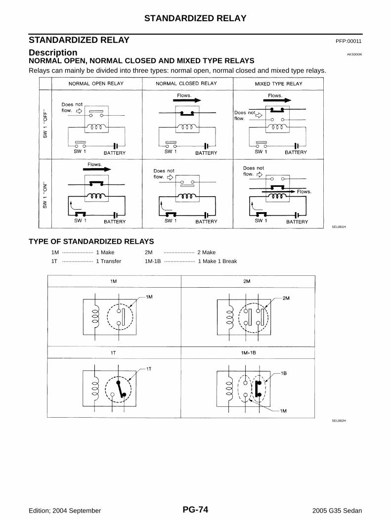
Description AKS000IK
NORMAL OPEN, NORMAL CLOSED AND MIXED TYPE RELAYSRelays can mainly be divided into three types: normal open, normal closed and mixed type relays.
TYPE OF STANDARDIZED RELAYS
SEL881H
1M ···················· 1 Make 2M ···················· 2 Make
1T ···················· 1 Transfer 1M·1B ···················· 1 Make 1 Break
SEL882H

STANDARDIZED RELAY
PG-75
C
D
E
F
G
H
I
J
L
M
A
B
PG
Edition; 2004 September 2005 G35 Sedan
SEL188W

PG-76
FUSE BLOCK - JUNCTION BOX (J/B)
Edition; 2004 September 2005 G35 Sedan
FUSE BLOCK - JUNCTION BOX (J/B) PFP:24350
Terminal Arrangement AKS000D7
CKIT0450E
FUSE, FUSIBLE LINK AND RELAY BOX
PG-77
C
D
E
F
G
H
I
J
L
M
A
B
PG
Edition; 2004 September 2005 G35 Sedan
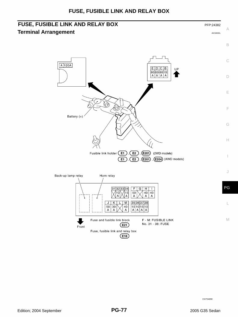
FUSE, FUSIBLE LINK AND RELAY BOX PFP:24382
Terminal Arrangement AKS000IL
CKIT0489E

PG-78
FUSE, FUSIBLE LINK AND RELAY BOX
Edition; 2004 September 2005 G35 Sedan


